EP2436818A1 - Washing and drying apparatus - Google Patents
Washing and drying apparatus Download PDFInfo
- Publication number
- EP2436818A1 EP2436818A1 EP11181937A EP11181937A EP2436818A1 EP 2436818 A1 EP2436818 A1 EP 2436818A1 EP 11181937 A EP11181937 A EP 11181937A EP 11181937 A EP11181937 A EP 11181937A EP 2436818 A1 EP2436818 A1 EP 2436818A1
- Authority
- EP
- European Patent Office
- Prior art keywords
- washing
- tilted surface
- water
- drainage
- dehumidifier
- Prior art date
- Legal status (The legal status is an assumption and is not a legal conclusion. Google has not performed a legal analysis and makes no representation as to the accuracy of the status listed.)
- Withdrawn
Links
- 238000005406 washing Methods 0.000 title claims abstract description 166
- 238000001035 drying Methods 0.000 title claims abstract description 131
- XLYOFNOQVPJJNP-UHFFFAOYSA-N water Substances O XLYOFNOQVPJJNP-UHFFFAOYSA-N 0.000 claims abstract description 202
- 238000005192 partition Methods 0.000 claims description 38
- 238000011144 upstream manufacturing Methods 0.000 claims description 36
- 238000007791 dehumidification Methods 0.000 claims description 29
- 239000007788 liquid Substances 0.000 claims description 19
- 238000010438 heat treatment Methods 0.000 claims description 17
- 238000007599 discharging Methods 0.000 abstract 1
- 238000009833 condensation Methods 0.000 description 40
- 230000005494 condensation Effects 0.000 description 40
- 239000006096 absorbing agent Substances 0.000 description 33
- 238000000034 method Methods 0.000 description 11
- 239000002826 coolant Substances 0.000 description 10
- 230000009467 reduction Effects 0.000 description 10
- 230000008569 process Effects 0.000 description 9
- 230000009471 action Effects 0.000 description 4
- 230000005484 gravity Effects 0.000 description 4
- 239000003599 detergent Substances 0.000 description 2
- 230000004044 response Effects 0.000 description 2
- 239000000725 suspension Substances 0.000 description 2
- 238000005352 clarification Methods 0.000 description 1
- 230000000295 complement effect Effects 0.000 description 1
- 230000006835 compression Effects 0.000 description 1
- 238000007906 compression Methods 0.000 description 1
- 238000001816 cooling Methods 0.000 description 1
- 230000006837 decompression Effects 0.000 description 1
- 230000000994 depressogenic effect Effects 0.000 description 1
- 238000010981 drying operation Methods 0.000 description 1
- 239000000428 dust Substances 0.000 description 1
- 238000005516 engineering process Methods 0.000 description 1
- 239000012530 fluid Substances 0.000 description 1
- 238000004519 manufacturing process Methods 0.000 description 1
- 239000011435 rock Substances 0.000 description 1
- 239000008400 supply water Substances 0.000 description 1
- 239000002699 waste material Substances 0.000 description 1
Images


Classifications
-
- D—TEXTILES; PAPER
- D06—TREATMENT OF TEXTILES OR THE LIKE; LAUNDERING; FLEXIBLE MATERIALS NOT OTHERWISE PROVIDED FOR
- D06F—LAUNDERING, DRYING, IRONING, PRESSING OR FOLDING TEXTILE ARTICLES
- D06F39/00—Details of washing machines not specific to a single type of machines covered by groups D06F9/00 - D06F27/00
- D06F39/08—Liquid supply or discharge arrangements
- D06F39/083—Liquid discharge or recirculation arrangements
-
- D—TEXTILES; PAPER
- D06—TREATMENT OF TEXTILES OR THE LIKE; LAUNDERING; FLEXIBLE MATERIALS NOT OTHERWISE PROVIDED FOR
- D06F—LAUNDERING, DRYING, IRONING, PRESSING OR FOLDING TEXTILE ARTICLES
- D06F25/00—Washing machines with receptacles, e.g. perforated, having a rotary movement, e.g. oscillatory movement, the receptacle serving both for washing and for centrifugally separating water from the laundry and having further drying means, e.g. using hot air
-
- D—TEXTILES; PAPER
- D06—TREATMENT OF TEXTILES OR THE LIKE; LAUNDERING; FLEXIBLE MATERIALS NOT OTHERWISE PROVIDED FOR
- D06F—LAUNDERING, DRYING, IRONING, PRESSING OR FOLDING TEXTILE ARTICLES
- D06F2103/00—Parameters monitored or detected for the control of domestic laundry washing machines, washer-dryers or laundry dryers
- D06F2103/18—Washing liquid level
-
- D—TEXTILES; PAPER
- D06—TREATMENT OF TEXTILES OR THE LIKE; LAUNDERING; FLEXIBLE MATERIALS NOT OTHERWISE PROVIDED FOR
- D06F—LAUNDERING, DRYING, IRONING, PRESSING OR FOLDING TEXTILE ARTICLES
- D06F2105/00—Systems or parameters controlled or affected by the control systems of washing machines, washer-dryers or laundry dryers
- D06F2105/02—Water supply
-
- D—TEXTILES; PAPER
- D06—TREATMENT OF TEXTILES OR THE LIKE; LAUNDERING; FLEXIBLE MATERIALS NOT OTHERWISE PROVIDED FOR
- D06F—LAUNDERING, DRYING, IRONING, PRESSING OR FOLDING TEXTILE ARTICLES
- D06F2105/00—Systems or parameters controlled or affected by the control systems of washing machines, washer-dryers or laundry dryers
- D06F2105/08—Draining of washing liquids
-
- D—TEXTILES; PAPER
- D06—TREATMENT OF TEXTILES OR THE LIKE; LAUNDERING; FLEXIBLE MATERIALS NOT OTHERWISE PROVIDED FOR
- D06F—LAUNDERING, DRYING, IRONING, PRESSING OR FOLDING TEXTILE ARTICLES
- D06F34/00—Details of control systems for washing machines, washer-dryers or laundry dryers
- D06F34/14—Arrangements for detecting or measuring specific parameters
-
- D—TEXTILES; PAPER
- D06—TREATMENT OF TEXTILES OR THE LIKE; LAUNDERING; FLEXIBLE MATERIALS NOT OTHERWISE PROVIDED FOR
- D06F—LAUNDERING, DRYING, IRONING, PRESSING OR FOLDING TEXTILE ARTICLES
- D06F58/00—Domestic laundry dryers
- D06F58/20—General details of domestic laundry dryers
- D06F58/206—Heat pump arrangements
Definitions
- the present invention is related to a washing and drying apparatus for washing and drying laundry.
- a washing and drying machine for washing and drying laundry typically comprises a drainage system configured to drain washing water, which has been used for washing laundry, and a circulation system configured to circulate dry air for drying the laundry.
- the drainage system comprises a drainage valve configured to control drainage of the washing water. The drainage valve is opened to drain the washing water as appropriate.
- the circulation system comprises a dehumidifier configured to remove water (moisture) from the dry air, which has been used to dry the laundry.
- Each of Japanese Patent Application Laid-open No. 2005-52533 and Japanese Patent Application Laid-open No. 2006-218067 discloses a washing and drying machine comprising a heat pump with a heat absorber for cooling dry air to condense moisture in the dry air.
- the heat absorber of the heat pump functions as the aforementioned dehumidifier.
- the washing and drying machine comprises a dedicated drainage pump, which is solely used to flow the water, which has been removed by the heat absorber, toward a drainage valve configured to control drainage of the washing water. If the drainage valve is opened and the drainage pump is operated, the water removed by the heat absorber is drained together with the washing water.
- the use of the dedicated drainage pump increases not only the manufacturing cost of the washing and drying machine but also the size and weight thereof.
- An object of the present invention is to provide a washing and drying apparatus with a drainage system which is effective for cost reduction, downsizing and lightweight of the washing and drying machine.
- a washing and drying apparatus has: a washing and drying tub configured to wash and dry laundry; a circulation system configured to circulate dry air to dry the laundry; and a drainage system configured to drain washing water used to wash the laundry, wherein the drainage system includes a drainage duct connected to the washing and drying tub and a drainage valve configured to control drainage of the washing water in the drainage duct, and the circulation system includes a dehumidifier configured to remove water in the dry air and a drain tube configured to guide the water removed by the dehumidifier to the drainage duct situated below the dehumidifier.
- washing and drying apparatus according to one embodiment is described hereinafter with reference to the accompanying drawings. It should be noted that directional terms used hereinafter such as “above”, “below”, “left”, “right” and alike are used only for the purpose of clarification of the description, and are not intended to limit methodologies of the washing and drying apparatus.
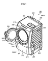
- Fig. 1 is a schematic perspective view of a washing and drying machine exemplified as the washing and drying apparatus according to the one embodiment.
- the washing and drying machine 100 comprises a housing 200 and a door 300.
- the housing 200 is formed into a generally rectangular boxed shape.
- the housing 200 includes an upright front wall 210, a back wall 220 opposite to the front wall 210, left and right walls 230, 240 which vertically stands between the front and back walls 210, 220, a top wall 250 which forms the upper surface of the housing 200, and a bottom wall 260 which forms the lower surface of the housing 200.
- the front wall 210 includes a lower wall 211 situated in a lower portion thereof, a central wall 212 above the lower wall 211, and an upper wall 213 above the central wall 212.
- the central wall 212 and the upper wall 213 are tilted upward to curve toward the back wall 220.
- the central wall 212 includes an annular concave surface 214 which forms a concave region substantially complementary to the substantially disk-shaped door 300.
- the concave surface 214 surrounds a feeding opening 215 configured to extend through a substantially central portion of the central wall 212.
- the feeding opening 215 communicates with a washing and drying tub (described later), which is stored inside the housing 200. A user may put and take clothing (laundry and alike) in and out of the housing 200 through the feeding opening 215.
- the washing and drying machine 100 comprises a hinge structure 330 which pivotally connects the door 300 to the housing 200.
- the hinge structure 330 allows the door 300 to pivot between a closing position where the door 300 closes the feeding opening 215 and an opening position where the door 300 opens the feeding opening 215.
- the door 300 pivoted to the closing position is accommodated in the concave region surrounded by the concave surface 214. It should be noted that the door 300 depicted in Fig. 1 is positioned at the opening position.
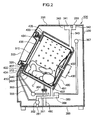
- Fig. 2 is a schematic cross-sectional view of the washing and drying machine 100 with the door 300 positioned at the closing position. Arrangements, shapes, and structures of elements in the housing 200 depicted in Fig. 2 should not be restrictively interpreted. The arrangements, shapes, and structures of the elements in the housing 200 may be appropriately determined in accordance with designs and functions of the washing and drying apparatus. The entire structure of the washing and drying machine 100 is further described with reference to Figs. 1 and 2 .
- a processing apparatus 400 configured to perform a drying process is constructed in the housing 200.
- the processing apparatus 400 executes processes required for washing and drying laundry C such as a washing process, a rinsing process, and a spin-drying process in addition to the drying process.
- the processing apparatus 400 comprises a washing and drying tub 410 configured to dry and wash the laundry C.
- the washing and drying tub 410 configured to store the laundry C includes a water tub 420 shaped in a bottomed cylinder which is supported but allowed to rock in the housing 200, and a rotary drum 440 shaped in a bottomed cylinder which is supported in the water tub 420.
- the processing apparatus 400 comprises a suspension 490 configured to elastically support the washing and drying tub 410.
- the suspension 490 connected to the bottom wall 260 of the housing 200 appropriately absorbs vibration during various processes such as the aforementioned drying process, washing process, rinsing process, and spin-drying process.
- the processing apparatus 400 further includes a motor 430 configured to rotate the rotary drum 440.
- the main body of the motor 430 is mounted to the outer surface of the bottom wall 431 of the water tub 420.
- the rotary shaft of the motor 430 extends through the bottom wall 431 of the water tub 420, and is connected to the bottom wall 432 of the rotary drum 440.
- the motor 430 rotates the rotary drum 440 during various processes such as the drying process, washing process, rinsing process, and spin-drying process.
- a front wall 433 opposite to the bottom wall 431 of the water tub 420 is provided with an opening 434 substantially concentric with the substantially circular door 300 at the closing position.
- a front wall 435 opposite to the bottom wall 432 of the rotary drum 440 is provided with an opening 436 substantially concentric with the opening 434 formed on the front wall 433 of the water tub 420.
- a user may turn the door 300 to the opening position to feed laundry C into the rotary drum 440 through the feeding opening 215.
- the processing apparatus 400 further comprises a bellows 437 situated between the central wall 212 of the housing 200 and the front wall 433 of the water tub 420.
- the water tub 420 is elastically connected to the housing 200 via the bellows 437.
- the door 300 includes a transparent window 310, which looks like a bottomed generally trapezoidal conical shape, and a substantially disk-like support frame 320 configured to support the window 310.
- the window 310 is inserted into the feeding opening 215 formed on the housing 200. If the door 300 is positioned at the closing position, a user may visually access the laundry C in the washing and drying tub 410 through the transparent window 310.
- the washing and drying machine 100 comprises a watering system 340 configured to supply water, which is used for washing laundry, to the washing and drying tub 410, and a circulatory drainage system 350 configured to circulate and drain the water, which is supplied to the washing and drying tub 410 (washing water).
- the watering system 340 is formed in an upper portion of the internal space of the housing 200.
- the circulatory drainage system 350 is formed in a lower portion of the internal space of the housing 200.
- the top wall 250 of the housing 200 is provided with a water inlet 253, which is connected to, for example, a hose (not shown).
- the watering system 340 comprises a storage chamber 341 configured to store detergent, and a first watering duct 342 which connects the water inlet 253 with the storage chamber 341.
- the storage chamber 341 is adjacent to the inner surface of the top wall 250 of the housing 200.
- the watering system 340 further comprises a second watering duct 343 which extends from the storage chamber 341 to the water tub 420.
- Water supplied through the water inlet 253 flows into the storage chamber 341 through the first watering duct 342.
- the water and the detergent are mixed up in the storage chamber 341 to become washing water.
- the washing water is supplied into the water tub 420 through the second watering duct 343.
- the water tub 420 is formed with an outlet port 423 from which the washing water is discharged, and an inlet port 424 through which the washing water flows into the water tub 420.
- the bottom wall 260 of the housing 200 is provided with a drainage port 261 from which the washing water is drained to the outside of the housing 200.
- the circulatory drainage system 350 comprises a drainage duct 351 which extends between the outlet port 423 of the water tub 420 and the drainage port 261 of the housing 200, and a drainage valve 352 which is mounted to the drainage duct 351.
- the drainage valve 352 is used to control drainage of the washing water to the outside of the housing 200.
- the drainage valve 352 is opened and closed as appropriate.
- the circulatory drainage system 350 is exemplified as the drainage system.
- the circulatory drainage system 350 comprises a circulation duct 353, which is branched from the drainage duct 351 before the drainage valve 352, and a circulation pump 354 which is mounted to the circulation duct 353.
- the circulation duct 353 is connected to the inlet port 424 of the water tub 420. If the drainage valve 352 is closed and the circulation pump 354 is operated, the washing water in the water tub 420 is sucked to the circulation pump 354. Thereafter, the washing water is pumped to the inlet port 424 by the circulation pump 354, and then is used for washing the laundry C in the washing and drying tub 410.
- the water tub 420 is further formed with a limitation hole 422 configured to limit a liquid level in the water tub 420.
- the circulatory drainage system 350 further comprises an overflow pipe 355 which is connected to the limitation hole 422.
- the overflow pipe 355 is also connected to the drainage duct 351 before the drainage valve 352. If the liquid level of the washing water in the water tub 420 exceeds a given level, the drainage valve 352 is opened.
- the redundant washing water in the water tub 420 flows into the overflow pipe 355 through the limitation hole 422, and is eventually drained from the drainage port 261 of the housing 200.
- the circulatory drainage system 350 further comprises a hollow block 356 which is mounted to the drainage duct 351, and a liquid level sensor 357 which is connected to the hollow block 356.
- a layer of the washing water and an air layer are formed in the hollow block 356 mounted between the drainage valve 352 and the washing and drying tub 410. Since the hollow block 356 is connected to the water tub 420 via the drainage duct 351, a thickness of the washing water layer in the hollow block 356 fluctuates correspondingly to the liquid level of the washing water in the water tub 420.
- the fluctuation in thickness of the washing water layer inside the hollow block 356 varies pressure of the air layer in the hollow block 356.
- the liquid level sensor 357 detects the fluctuation in the air layer pressure in the hollow block 356.
- the output from the liquid level sensor 357 is used to adjust the liquid level of the washing water in the water tub 420.
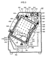
- Fig. 3 is a schematic cross-sectional view of the washing and drying machine 100. The entire structure of the washing and drying machine 100 is further described with reference to Figs. 1 and 3 .
- the washing and drying machine 100 has a circulation system 600 configured to circulate dry air for drying the laundry C stored in the rotary drum 440.
- the circulation system 600 is also constructed in the housing 200, like the washing and drying tub 410 and the circulatory drainage system 350.
- the water tub 420 includes a cylindrical circumferential wall 438 which extends between the bottom and front walls 431, 433.
- the circumferential wall 438 of the water tub 420 is provided with an exhaust port 601 through which the dry air is exhausted from the washing and drying tub 410.
- the bottom wall 431 of the water tub 420 is provided with an inflow port 643 through which the dry air is sucked into the washing and drying tub 410.
- the circulation system 600 circulates the dry air to dry the laundry C between the exhaust and inflow ports 601, 643.
- the bottom wall 432 of the rotary drum 440 is provided with a bottom hole 645 to introduce the dry air, which has been sucked through the inflow port 643, into the rotary drum 440.
- the rotary drum 440 includes a cylindrical circumferential wall 439 which extends between the bottom and front walls 432, 435.
- the circumferential wall 439 of the rotary drum 440 is provided with a lot of circumferential holes 646 to flow the dry air into the exhaust port 601 formed on the circumferential wall 438 of the water tub 420.
- the dry air from the bottom hole 645 to the circumferential holes 646 facilitates to dry the laundry C in the rotary drum 440.
- the circulation system 600 comprises a first duct 610, which protrudes from the exhaust port 601 of the water tub 420 and extends along the top wall 250 of the housing 200, a filter apparatus 700 which removes lint (dust such as a yarn waste) from the dry air discharged from the washing and drying tub 410, a heat pump 630 adjacent to the filter apparatus 700, and a fan 621 which circulates the dry air.
- the first duct 610 includes a support plate described later, and a connection duct 602 which connects the support plate to the exhaust port 601. In the present embodiment, the support plate supports the filter apparatus 700, the heat pump 630, and the fan 621.
- the fan 621 is exemplified as the blower.
- the connection duct 602 is exemplified as the connection pipe.
- the first duct 610 guides the dry air from the washing and drying tub 410 to the fan 621.
- the filter apparatus 700 in the first duct 610 removes the lint from the dry air.
- the heat pump 630 performs heat exchange with the dry air to dehumidify and heat the dry air.
- the fan 621 sucks the dehumidified and heated dry air, and then sends the dry air to the washing and drying tub 410.
- the circulation system 600 further comprises a second duct 620 which guides the dry air from the fan 621 to the washing and drying tub 410.
- the dry air sent from the fan 621 is guided by the second duct 620, and flows into the washing and drying tub 410 via the inflow port 643.
- the circulation system 600 comprises a branch duct 650 which is branched from the second duct 620, and a switching valve 651 situated at a junction between the second and branch ducts 620, 650.
- the branch duct 650 includes a tip end which communicates with the opening 436 formed on the front wall 435 of the rotary drum 440.
- the switching valve 651 pivots between a first position where the switching valve 651 blocks the dry air flow from the fan 621 to the inflow port 643 and a second position where the switching valve 651 aligns the dry air flow from the fan 621 to the inflow port 643.
- the switching valve 651 is at the first position, most of the dry air is blown on the laundry C from the opening 436 of the rotary drum 440 through the branch duct 650 whereas if the switching valve 651 is at the second position, most of the dry air flows to the inflow port 643. After the drying process is started, the switching valve 651 is set to the second position for a given time period. Thereafter, the switching valve 651 is set to the first position until the drying process is completed. Thus, the drying operation is changed in response to a dryness level of the laundry C.
- Fig. 4 is a schematic view diagrammatically showing the heat pump 630.
- the heat pump 630 is described with reference to Figs. 3 and 4 .
- the heat pump 630 comprises a circulation pipe 631. Coolant flows in the circulation pipe 631.
- the heat pump 630 comprises a compressor 632 configured to compresses the coolant.
- the compressor 632 is situated along the path of the circulation pipe 631, which contours a closed loop.
- the circulation pipe 631 in which the coolant sent from the compressor 632 flows, protrudes into the first duct 610 to form a radiator 633.
- the radiator 633 configured to radiate heat of the coolant heated by means of compression in the compressor 632 includes the circulation pipe 631 which meanders in the first duct 610, and fins 638 which are attached to the circulation pipe 631.
- the dry air passing through the first duct 610 is heated by the radiator 633.
- the radiator 633 is exemplified as the heater.
- the heat pump 630 has a decompressor 634 configured to decompress the coolant, which has been highly compressed by the compressor 632.
- the coolant passing through the radiator 633 is simultaneously decompressed and cooled by the decompressor 634.
- the coolant passing through the decompressor 634 flows in the circulation pipe 631, which protrudes again into the first duct 610 to form a heat absorber 635.
- the heat absorber 635 configured to absorb heat by means of the coolant cooled by decompression in the decompressor 634 includes the circulation pipe 631 which meanders in the first duct 610, and fins 636 which are attached to the circulation pipe 631.
- the heat of the dry air in the first duct 610 is absorbed by the heat absorber 635.
- the moisture in the dry air is condensed on the fins 636 and/or the circulation pipe 631, and is removed from the dry air.
- condensation water the moisture in the dry air condensed on the fins 636 and/or the circulation pipe 631
- the heat absorber 635 is exemplified as the dehumidifier.
- the circulation system 600 comprises a drain tube 639 connected between the first duct 610 and the drainage duct 351 below the heat absorber 635.
- the drain tube 639 is connected to the hollow block 356 provided in the drainage duct 351.
- the drain tube 639 is used to guide the condensation water to the drainage duct 351.
- the heat pump 630 is adjacent to the top wall 250 of the housing 200 to cause a relatively large water head of the condensation water in the drain tube 639. Thus, the condensation water appropriately flows into the drainage duct 351 by the gravity action.
- the circulation system 600 further comprises a check valve 637 which is attached to the drain tube 639. Most of the internal space in the first duct 610 is negatively pressurized under operation of the fan 621.
- the check valve 637 checks the negative pressure environment in the first duct 610 along the path of the drain tube 639, so that it becomes less likely that fluid elevates from the drainage duct 351 to the first duct 610.
- the attachment position of the check valve 637 in the drain tube 639 is appropriately determined such that the water head between the check valve 637 and the first duct 610 becomes high enough to send the condensation water into the drainage duct 351.
- Fig. 5 is a schematic plan view of the filter apparatus 700, the heat pump 630, and the fan 621 which are situated on the support plate.
- Fig. 6 is a schematic plan view of the support plate.
- Fig. 7 is a schematic right side view of the support plate. The support plate is described with reference to Figs. 3 and 5 to 7 .
- the support plate 500 includes a bottom wall 510 which supports the filter apparatus 700, the heat pump 630, and the fan 621, and a circumferential wall 520 which vertically stands from the circumferential edge of the bottom wall 510.
- the circumferential wall 520 includes a connection wall 521 which is connected to the connection duct 602.
- the connection wall 521 is formed with an opening 522 which is connected to the connection duct 602.
- connection wall 521 removes lint from the dry air introduced from the opening 522.
- the fan 621 is mounted on the bottom wall 510 so that the fan 21 is offset leftward with respect to the opening 522. It should be noted that, in the present embodiment, the connection wall 521 stands from the front edge of the bottom wall 510 whereas the fan 621 is mounted near the back edge of the bottom wall 510.
- the heat absorber 635 of the heat pump 630 adjacent to the filter apparatus 700 removes the moisture from the dry air immediately after the dry air passes through the filter apparatus 700.
- a right portion 635R of the heat absorber 635 faces the opening 522.
- a left portion 635L adjacent to the right portion 635R faces the fan 621.
- the support plate 500 configured to support the heat absorber 635 is exemplified as the support element.
- the right portion 63 5R of the heat absorber 635 is exemplified as the first dehumidification section.
- the left portion 635L of the heat absorber 635 is exemplified as the second humidification section.
- the radiator 633 of the heat pump 630 is adjacent to the heat absorber 635.
- the radiator 633 situated between the heat absorber 635 and the fan 621 has the substantially same shape and size as the heat absorber 635.
- a right portion 633R of the radiator 633 is adjacent to the right portion 635R of the heat absorber 635.
- a left portion 633L of the radiator 633 is adjacent to the left portion 635L of the heat absorber 635.
- the right portion 633R of the radiator 633 is exemplified as the first heating section.
- the left portion 633L adjacent to the right portion 633R is exemplified as the second heating section.
- the bottom wall 510 includes a main tilted surface 511 which is formed at the right sides of the heat absorber 635 and the radiator 633.
- the condensation water from the heat absorber 635 flows to the main tilted surface 511.
- the main tilted surface 511 is tilted such that the condensation water on the main tilted surface 511 flows backward.
- the support plate 500 includes a pool 530 adjacent to a backside end of the main tilted surface 511.
- the pool 530 is depressed downward with respect to the main tilted surface 511. Consequently, the condensation water reached the backside end of the main tilted surface 511 flows into the pool 530.
- the pool 530 may temporarily stores a given amount of the condensation water.
- the support plate 500 includes a connection port 531 which is formed at the bottom of the pool 530.
- the connection port 531 formed to drain the condensation water in the pool 530 from the support plate 500 is connected to the upper end of the drain tube 639.
- the main tilted surface 511 is tilted to guide the condensation water to the pool 530.
- the connection port 531 is exemplified as the drainage port.
- the support plate 500 includes a cylindrical wall 540 which surrounds the compressor 632 of the heat pump 630.
- the cylindrical wall 540 is adjacent to the pool 530.
- Fig. 8 is a schematic right side view of the heat absorber 635 and the radiator 633 supported by the support plate 500.
- the support plate 500 is described with reference to Figs. 5 , 6 , and 8 .
- the support plate 500 includes a right support wall 512 which supports the right ends of the heat absorber 635 and the radiator 633.
- the right support wall 512 defines the left boundary of the main tilted surface 511.
- the left ends of the heat absorber 635 and the radiator 633 are appropriately supported by a left support wall 513 which protrudes from the circumferential wall 520 of the support plate 500.
- the right support wall 512 which protrudes from the upper surface of the bottom wall 510 includes a first right support wall 514 along the front and bottom edges of the right side surface of the heat absorber 635, a second right support wall 515 along the back edge and a part of the bottom edge of the right side surface of the radiator 633, and a third right support wall 516 which supports the bottom edge of the right side surface of the radiator 633 between the first and second right support walls 514, 515.
- the right support wall 512 is formed with notches 517 and 518.
- the notch 517 is formed between the first and third right support walls 514, 516.
- the notch 518 is formed between the second and third right support walls 515, 516.
- the support plate 500 includes a boundary wall 541 which protrudes upward between the heat absorber 635 and the radiator 633.
- the bottom wall 510 of the support plate 500 includes a first tilted surface 542 which is formed below the heat absorber 635, and a second tilted surface 543 which is formed below the radiator 633.
- the right support wall 512 separates the main tilted surface 511 from the first tilted surface 542.
- the right support wall 512 also separates the main tilted surface 511 from the second tilted surface 543.
- the right support wall 512 which protrudes between the main tilted surface 511 and the first and/or second tilted surfaces 542, 543 is exemplified as the support wall.
- the support plate 500 comprises a first partition wall 546 which partitions the first tilted surface 542 into a first upstream tilted surface 544 and a first downstream tilted surface 545 which is farther from the connection wall 521 (situated nearby the fan 621) than the first upstream tilted surface 544.
- the first partition wall 546 which protrudes from the first tilted surface 542 extends in a left-to-right direction (a transverse direction with respect to the dry air flow toward the fan 621).
- the support plate 500 comprises a second partition wall 549 which partitions the second tilted surface 543 into a second upstream tilted surface 547 and a second downstream tilted surface 548 which is farther from the connection wall 521 (situated nearby the fan 621) than the second upstream tilted surface 547.
- the second partition wall 549 which protrudes from the second tilted surface 543 extends in the left-to-right direction (a transverse direction with respect to the dry air flow toward the fan 621).
- Fig. 9 is a schematic cross-sectional view around a connection between the right support wall 512 and the first partition wall 546.
- the support plate 500 is further described with reference to Figs. 5 , 6 , and 9 .
- a series of the fins 636 of the heat absorber 635 are disposed along the first partition wall 546.
- the circulation pipe 631 extends through the fins 636.
- the fins 636 are sufficiently cooled by the coolant flowing in the circulation pipe 631.
- the dry air which is brought into contact with the fins 636 and/or the circulation pipe 631 is cooled.
- the condensation water occurs on the surfaces of the fins 636 and/or the circulation pipe 631.
- the condensation water drips onto the first tilted surface 542 (the first upstream tilted surface 544, the first downstream tilted surface 545) formed below the heat absorber 635.
- the first partition wall 546 is formed with a notch 551 nearby the right support wall 512.
- the notch 551 of the first partition wall 546 allows the condensation water to flow from the fist upstream tilted surface 544 to the first downstream tilted surface 545.
- the notch 517 formed between the first and third right support walls 514, 516 allows the condensation water to flow from the first downstream tilted surface 545 to the main tilted surface 511.
- the notch 517 formed between the first and third right support walls 514, 516 is exemplified as the first notch.
- the notch 551 of the first partition wall 546 is exemplified as the second notch.
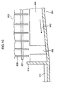
- Fig. 10 is a schematic cross-sectional view around a connection between the right support wall 512 and the second partition wall 549.
- the support plate 500 is further described with reference to Figs. 4 to 6 and 10 .
- a series of the fins 638 of the radiator 633 are disposed along the second partition wall 549.
- the circulation pipe 631 extends through the fins 638.
- the coolant in the radiator 633 is sufficiently heated by the compressor 632. Consequently, unlike the heat absorber 635, it is less likely that there is condensation directly on the fins 638 or the circulation pipe 631 in the radiator 633. However, the condensation water occurred in the heat absorber 635 is potentially carried by the dry air flow and adheres to the fins 638 and the circulation pipe 631 in the radiator 633.
- boundary wall 541 protruding between the first downstream tilted surface 545 and the second upstream tilted surface 547 extends in the left-to-right direction (a transverse direction with respect to the dry air flow toward the fan 621) to partially interfere with transit of the condensation water from the heat absorber 635 to the radiator 633.
- the condensation water adhered to the fins 638 and the circulation pipe 631 in the radiator 633 drips onto the second tilted surface 543 (the second upstream tilted surface 547, the second downstream tilted surface 548) formed below the radiator 633.
- the second tilted surface 543 is tilted such that the condensation water dripped on the second tilted surface 543 flows toward the right support wall 512/the main tilted surface 511 (i.e. from below the left portion 633L of the radiator 633 toward below the right portion 633R thereof).
- the second partition wall 549 is formed with a notch 552 nearby the right support wall 512.
- the notch 552 of the second partition wall 549 allows the condensation water to flow from the second upstream tilted surface 547 to the second downstream tilted surface 548.
- the notch 518 formed between the second and third right support walls 515, 516 allows the condensation water to flow from the second downstream tilted surface 548 to the main tilted surface 511.
- the notch 518 formed between the second and third right support walls 515, 516 is exemplified as the third notch.
- the notch 552 of the second partition wall 549 is exemplified as the fourth notch.
- a drainage process of the condensation water is described with reference to Figs. 2 , 3 , and 6 .
- the condensation water dripped on the first and/or second tilted surfaces 542, 543 is flows onto the main tilted surface 511. Thereafter, the condensation water is collected into the pool 530.
- the condensation water stored in the pool 530 occasionally flows into the drain tube 639, which results in a high water head between the check valve 637, which is attached to the drain tube 639, and the connection port 531.
- the high head causes the condensation water flow toward the portion below the check valve 637 against the negative pressure environment resulting from the operation of the fan 621.
- the condensation water is occasionally sent to the hollow block 356 below the check valve 637.
- the condensation water flow from the support plate 500 to the hollow block 356 is caused by the gravity action. Consequently, the condensation water flow becomes less influential to the circulation of the dry air by the fan 621.
- the condensation water flow is caused by a pump.
- the suction of the pump frequently affects the dry air circulation.
- the condensation water flow is independent from the dry air circulation.
- the condensation water flow into the hollow block 356 potentially increases the thickness of the washing water layer in the hollow block 356.
- the liquid level sensor 357 may detect a fluctuation in the air pressure in the hollow block 356 resulting from the condensation water flow into the hollow block 356.
- the drainage valve 352 may be opened in response to the increase in air pressure in the hollow block 356, so that the condensation water is drained to the outside of the housing 200. Alternatively, if the drainage valve 352 is opened in accordance with a program for conducting various processes such as the washing process, the rinsing process, and the spin-drying process, the condensation water may be drained together with the washing water.
- the washing and drying machine 100 may execute the appropriate drainage of the condensation water without an additional component or program. It is also unnecessary to use conventional dedicated pump equipment for drainage of the condensation water.
- the aforementioned embodiment mainly includes a washing and drying apparatus with the following structure.
- the washing and drying apparatus with the following structure may have a drainage system which is effective for cost reduction, downsizing and lightweight of the washing and drying machine.
- a washing and drying apparatus has: a washing and drying tub configured to wash and dry laundry; a circulation system configured to circulate dry air to dry the laundry; and a drainage system configured to drain washing water used to wash the laundry, wherein the drainage system includes a drainage duct connected to the washing and drying tub and a drainage valve configured to control drainage of the washing water in the drainage duct, and the circulation system includes a dehumidifier configured to remove water in the dry air and a drain tube configured to guide the water removed by the dehumidifier to the drainage duct situated below the dehumidifier.
- the circulation system circulates the dry air to dry the laundry.
- the drainage system configured to drainage the washing water, which has been used to wash the laundry includes the drainage duct connected to the washing and drying tub and the drainage valve configured to control drainage of the washing water in the drainage duct.
- the drainage duct is situated below the dehumidifier configured to remove the water contained in the dry air. Consequently, the water removed by the dehumidifier is guided into the drain tube, and then is introduced into the drainage duct by the gravity action. Therefore, the drainage of the water removed by the dehumidifier is accomplished without a dedicated pump, which results in the washing and drying apparatus having the drainage system that is effective for cost reduction, downsizing and lightweight of the washing and drying machine.
- the circulation system preferably includes a blower configured to circulate the dry air, a first duct configured to guide the dry air from the washing and drying tub to the blower, a second duct configured to guide the dry air from the blower to the washing and drying tub and a check valve attached to the drain tube, and the dehumidifier removes the water from the dry air flowing in the first duct.
- the dry air moves from the washing and drying tub to the blower through the first duct, and then moves from the blower to the washing and drying tub through the second duct.
- the blower circulates the dry air along the washing and drying tub, the first duct and the second ducts. Operation of the blower causes a negative pressure environment in the first duct, which results in a dry air flow toward the blower.
- the check valve attached to the drain tube configured to guide the water, which has been removed by the dehumidifier, to the drainage duct makes it less influential to the drainage duct that the operation of the blower causes the negative pressure environment and causes a water head large enough to maintain the water flow toward the drainage duct. Consequently, the drainage of the water removed by the dehumidifier is accomplished without a dedicated pump, which results in the washing and drying apparatus having the drainage system that is effective for cost reduction, downsizing and lightweight of the washing and drying machine.
- the first duct preferably a support element configured to support the dehumidifier
- the support element includes a drainage port connected to the drain duct, a main tilted surface tilted to guide the water removed by the dehumidifier to the drainage port, a first tilted surface below the dehumidifier, and a support wall which protrudes between the main tilted surface and the first tilted surface to support the dehumidifier, the first tilted surface is tilted such that the water removed by the dehumidifier flows toward the main tilted surface, and the support wall is formed with a first notch which allows the water to flow from the first tilted surface to the main tilted surface.
- the support element configured to support the dehumidifier includes the drainage port connected to the drain tube, the main tilted surface tilted to guide the water, which has been removed by the dehumidifier, to the drainage port, the first tilted surface below the dehumidifier, and the support wall which protrudes between the main tilted surface and the first tilted surface to support the dehumidifier.
- the water removed by the dehumidifier drips onto the first tilted surface by the gravity action. Since the first tilted surface is tilted such that the water, which has been removed by the dehumidifier, flows to the main tilted surface, the water on the first tilted surface flows to the main tilted surface.
- the first duct preferably includes a connection pipe configured to connect the washing and drying tub with the support element
- the support element supporting the blower includes a connection wall formed with an opening connected to the connection pipe
- the dehumidifier includes a first dehumidification section facing the opening and a second dehumidification section adjacent to the first dehumidification section, the second dehumidification section faces the blower, and the first tilted surface is tilted such that the water removed by the second dehumidification section flows below the first dehumidification section.
- the first duct includes the connection pipe configured to connect the washing and drying tub with the support element.
- the support element configured to support the blower includes the connection wall formed with the opening connected to the connection pipe.
- the dehumidifier includes the first dehumidification section facing the opening and the second dehumidification section adjacent to the first dehumidification section.
- the second dehumidification section faces the blower. Consequently, the dry air moving from the opening toward the blower obliquely traverses the dehumidifier. As a result, it takes a relatively long time period for the dry air to pass through the dehumidifier, which results in more effective dehumidification of the dry air.
- the first tilted surface is tilted such that the water removed by the second dehumidification section flows underneath the first dehumidification section. Consequently, the water is accumulated underneath the first dehumidification section so that the water becomes less sensitive to the dry air flow obliquely traversing the dehumidifier from the opening toward the blower. Thus, the water removed by the dehumidifier becomes less likely to be blown up toward the blower.
- the support element preferably includes a first partition wall configured to partition the first tilted surface into a first upstream tilted surface and a first downstream tilted surface, which is farther from the connection wall than the first upstream tilted surface, the first partition wall is formed with a second notch which allows the water to flow from the first upstream tilted surface to the first downstream tilted surface near the support wall, and the first notch allows the water to flow from the first downstream tilted surface to the main tilted surface.
- the support element includes the first partition wall configured to partition the first tilted surface into the first upstream tilted surface and the first downstream tilted surface, which is farther from the connection wall than the first upstream tilted surface. Since the first upstream tilted surface is tilted such that the water removed by the second dehumidification section flows underneath the first dehumidification section, the water dripped on the first upstream tilted surface from the dehumidifier moves toward the support wall. It is likely that the first partition wall prevents the water flowing on the first upstream tilted surface from be blown up by of the dry air flow toward the blower.
- the first partition wall is formed with the second notch near the support wall.
- the water flows from the first upstream tilted surface to the first downstream tilted surface through the second notch, and then flows from the first downstream tilted surface onto the main tilted surface through the first notch. Thereafter, the water, which has been removed by the dehumidifier, flows on the main tilted surface tilted to guide the water, and flows into the drain tube via the drainage port. Consequently, the drainage of the water removed by the dehumidifier is accomplished without a dedicated pump, which results in the washing and drying apparatus having the drainage system that is effective for cost reduction, downsizing and lightweight of the washing and drying machine.
- the washing and drying apparatus preferably further has a heater configured to heat the dry air
- the support wall supports the heater situated between the dehumidifier and the blower
- the support element includes a second tilted surface below the heater
- the second tilted surface is tilted such that the water removed by the dehumidifier flows to the main tilted surface
- the support wall separating the main tilted surface from the second tilted surface is formed with a third notch which allows the water to flow from the second tilted surface to the main tilted surface.
- the heater heats the dry air, so that the laundry is more effectively dried by the dry air flowing into the washing and drying tub through the second duct.
- the support wall supports the heater between the dehumidifier and the blower.
- the support element includes the second tilted surface below the heater. The second tilted surface receives the water, which has tapped into the dry air flow toward the blower and reached the heater from the dehumidifier. Thereafter, the water flows on the second tilted surface toward the main tilted surface.
- the support wall separating the main tilted surface from the second tilted surface is formed with the third notch, which allows the water to flow from the second tilted surface to the main tilted surface.
- the water flows from the second tilted surface toward the main tilted surface through the third notch. Thereafter, the water, which has removed by the dehumidifier, flows on the main tilted surface tilted to guide the water toward the drainage port, and then flows into the drain tube via the drainage port. Consequently, the drainage of the water removed by the dehumidifier is accomplished without a dedicated pump, which results in the washing and drying apparatus having the drainage system that is effective for cost reduction, downsizing and lightweight of the washing and drying machine.
- the heater preferably includes a first heating section adjacent to the first dehumidification section and a second heating section adjacent to the second dehumidification section, and the second tilted surface is tilted such that the water below the second heating section flows underneath the first heating section.
- the first heating section of the heater is adjacent to the first dehumidification section.
- the second heating section of the heater is adjacent to the second dehumidification section. Consequently, the dry air moving from the opening toward the blower obliquely traverses the heater, so that it takes a relatively long time period for the dry air to pass through the heater. Therefore the dry air is more effectively heated.
- the second tilted surface is tilted such that the water below the second heating section flows underneath the first heating section. Consequently, the water is accumulated below the first heating section, so that the dry air flow obliquely traversing the heater from the opening toward the blower becomes less influential to the accumulated water. Thus, the water removed by the dehumidifier becomes less likely to be blown up toward the blower.
- the support element preferably includes a second partition wall configured to partition the second tilted surface into a second upstream tilted surface and a second downstream tilted surface which is closer to the blower than the second upstream tilted surface, the second partition wall is formed with a fourth notch which allows the water to flow from the second upstream tilted surface to the second downstream tilted surface near the support wall, and the third notch allows the water to flow from the second downstream tilted surface to the main tilted surface.
- the support element includes the second partition wall configured to partition the second tilted surface into the second upstream tilted surface and the second downstream tilted surface, which is farther from the connection wall than the second upstream tilted surface. Since the second upstream tilted surface is tilted such that the water below the second heating section flows underneath the first heating section, the water dripped on the second upstream tilted surface from the heater moves toward the support wall. It is likely that the second partition wall prevents the water flowing on the second upstream tilted surface from being blown up by the dry air flow toward the blower.
- the second partition wall is formed with the third notch near the support wall.
- the water flows from the second upstream tilted surface to the second downstream tilted surface through the fourth notch, and then flows from the second downstream tilted surface onto the main tilted surface through the third notch. Thereafter, the water, which has been removed by the dehumidifier, toward the drainage port, flows on the main tilted surface tilted to guide the water, and then flows into the drain tube via the drainage port. Consequently, the drainage of the water removed by the dehumidifier is accomplished without a dedicated pump, which results in the washing and drying apparatus having the drainage system that is effective for cost reduction, downsizing and lightweight of the washing and drying machine.
- the support element preferably includes a boundary wall protruding between the first downstream tilted surface and the second upstream tilted surface.
- the boundary wall protruding between the first downstream tilted surface and the second upstream tilted surface is likely to prevent the water on the first downstream tilted surface below the dehumidifier from being blown up by the dry air flow toward the blower.
- the drainage system preferably includes a hollow block provided in the drainage duct and a liquid level sensor configured to detect a liquid level in the washing and drying tub, a layer of the washing water and an air layer are formed in the hollow block, and the liquid level sensor detects a fluctuation in pressure of the air layer resulting from a fluctuation in thickness of the layer of the washing water in the hollow block which corresponds to a liquid level in the washing and drying tub.
- the layer of the washing water and the air layer are formed in the hollow block provided in the drainage duct.
- the thickness of the layer of the washing water in the hollow block fluctuates correspondingly to the liquid level in the washing and drying tub.
- the fluctuation in the thickness of the layer of the washing water in the hollow block causes the fluctuation in the pressure of the air layer in the hollow block. Therefore the liquid level sensor detecting the fluctuation in the pressure of the air layer may find the liquid level in the washing and drying tub.
- the hollow block is preferably situated between the drainage valve and the washing and drying tub, and the drain duct is connected to the hollow block.
- the drain tube is connected to the hollow block between the drainage valve and the washing and drying tub. Consequently, the water flowing downward along the drain tube drops onto the layer of the washing water in the hollow block. Thereafter, the drainage valve is opened to drainage the water. Therefore, the drainage of the water removed by the dehumidifier is accomplished without a dedicated pump, which results in the washing and drying apparatus having the drainage system that is effective for cost reduction, downsizing and lightweight of the washing and drying machine.
- the washing and drying apparatus preferably further has a housing configured to store the washing and drying tub, the circulation system, and the drainage system, wherein the housing includes a top wall forming an upper surface of the housing, and the dehumidifier is adjacent to the top wall.
- the dehumidifier is adjacent to the top wall forming the upper surface of the housing configured to store the washing and drying tub, the circulation system, and the drainage system, which results in a relatively high water head in the drain tube. Consequently, the drainage of the water removed by the dehumidifier is accomplished without a dedicated pump, which results in the washing and drying apparatus having the drainage system that is effective for cost reduction, downsizing and lightweight of the washing and drying machine.
- the methodologies of the present embodiment are preferably used for a washing and drying machine.
Landscapes
- Engineering & Computer Science (AREA)
- Textile Engineering (AREA)
- Detail Structures Of Washing Machines And Dryers (AREA)
- Main Body Construction Of Washing Machines And Laundry Dryers (AREA)
Abstract
A washing and drying apparatus (100) has a washing and drying tub (410) for washing and drying laundry (C), a circulation system (600) for circulating dry air for drying the laundry (C), and a drainage system (350) for discharging a washing water used to wash the laundry (C). The drainage system (350) includes a drainage duct (351) connected to the washing and drying tub (410) and a drainage valve (352) for controlling drainage of the washing water in the drainage duct (351), and the circulation system (600) includes a dehumidifier (635) for removing water contained in the dry air and a drain tube (639) for guiding the water removed by the dehumidifier. (635) to the drainage duct (351) below the dehumidifier (635).
Description
- The present invention is related to a washing and drying apparatus for washing and drying laundry.
- A washing and drying machine for washing and drying laundry typically comprises a drainage system configured to drain washing water, which has been used for washing laundry, and a circulation system configured to circulate dry air for drying the laundry. The drainage system comprises a drainage valve configured to control drainage of the washing water. The drainage valve is opened to drain the washing water as appropriate. In many cases, the circulation system comprises a dehumidifier configured to remove water (moisture) from the dry air, which has been used to dry the laundry.
- Each of Japanese Patent Application Laid-open No.
2005-52533 2006-218067 - In accordance with the aforementioned Patent Documents, the washing and drying machine comprises a dedicated drainage pump, which is solely used to flow the water, which has been removed by the heat absorber, toward a drainage valve configured to control drainage of the washing water. If the drainage valve is opened and the drainage pump is operated, the water removed by the heat absorber is drained together with the washing water.
- The use of the dedicated drainage pump increases not only the manufacturing cost of the washing and drying machine but also the size and weight thereof.
- An object of the present invention is to provide a washing and drying apparatus with a drainage system which is effective for cost reduction, downsizing and lightweight of the washing and drying machine.
- A washing and drying apparatus according to one aspect of the present invention has: a washing and drying tub configured to wash and dry laundry; a circulation system configured to circulate dry air to dry the laundry; and a drainage system configured to drain washing water used to wash the laundry, wherein the drainage system includes a drainage duct connected to the washing and drying tub and a drainage valve configured to control drainage of the washing water in the drainage duct, and the circulation system includes a dehumidifier configured to remove water in the dry air and a drain tube configured to guide the water removed by the dehumidifier to the drainage duct situated below the dehumidifier.
-
-
Fig. 1 is a schematic perspective view of a washing and drying machine according to one embodiment; -
Fig. 2 is a schematic cross-sectional view of the washing and drying machine depicted inFig. 1 ; -
Fig. 3 is a schematic cross-sectional view of the washing and drying machine depicted inFig. 1 ; -
Fig. 4 is a schematic view of a heat pump of the washing and drying machine depicted inFig. 1 ; -
Fig. 5 is a schematic plan view of the heat pump depicted inFig. 4 and a support plate configured to support the heat pump; -
Fig. 6 is a schematic plan view of the support plate depicted inFig. 5 ; -
Fig. 7 is a schematic side view of the support plate depicted inFig. 6 ; -
Fig. 8 is a schematic view of a right support wall of the support plate depicted inFig. 6 ; -
Fig. 9 is a schematic view of a first partition wall of the support plate depicted inFig. 6 ; and -
Fig. 10 is a schematic view of a second partition wall of the support plate depicted inFig. 6 . - A washing and drying apparatus according to one embodiment is described hereinafter with reference to the accompanying drawings. It should be noted that directional terms used hereinafter such as "above", "below", "left", "right" and alike are used only for the purpose of clarification of the description, and are not intended to limit methodologies of the washing and drying apparatus.
-
Fig. 1 is a schematic perspective view of a washing and drying machine exemplified as the washing and drying apparatus according to the one embodiment. - The washing and
drying machine 100 comprises ahousing 200 and adoor 300. Thehousing 200 is formed into a generally rectangular boxed shape. Thehousing 200 includes anupright front wall 210, aback wall 220 opposite to thefront wall 210, left andright walls back walls top wall 250 which forms the upper surface of thehousing 200, and abottom wall 260 which forms the lower surface of thehousing 200. - The
front wall 210 includes alower wall 211 situated in a lower portion thereof, acentral wall 212 above thelower wall 211, and anupper wall 213 above thecentral wall 212. Thecentral wall 212 and theupper wall 213 are tilted upward to curve toward theback wall 220. - The
central wall 212 includes an annularconcave surface 214 which forms a concave region substantially complementary to the substantially disk-shaped door 300. Theconcave surface 214 surrounds afeeding opening 215 configured to extend through a substantially central portion of thecentral wall 212. The feeding opening 215 communicates with a washing and drying tub (described later), which is stored inside thehousing 200. A user may put and take clothing (laundry and alike) in and out of thehousing 200 through thefeeding opening 215. - The washing and
drying machine 100 comprises ahinge structure 330 which pivotally connects thedoor 300 to thehousing 200. Thehinge structure 330 allows thedoor 300 to pivot between a closing position where thedoor 300 closes the feeding opening 215 and an opening position where thedoor 300 opens the feeding opening 215. Thedoor 300 pivoted to the closing position is accommodated in the concave region surrounded by theconcave surface 214. It should be noted that thedoor 300 depicted inFig. 1 is positioned at the opening position. -
Fig. 2 is a schematic cross-sectional view of the washing anddrying machine 100 with thedoor 300 positioned at the closing position. Arrangements, shapes, and structures of elements in thehousing 200 depicted inFig. 2 should not be restrictively interpreted. The arrangements, shapes, and structures of the elements in thehousing 200 may be appropriately determined in accordance with designs and functions of the washing and drying apparatus. The entire structure of the washing anddrying machine 100 is further described with reference toFigs. 1 and2 . - As shown in
Fig. 2 , aprocessing apparatus 400 configured to perform a drying process is constructed in thehousing 200. In the present embodiment, theprocessing apparatus 400 executes processes required for washing and drying laundry C such as a washing process, a rinsing process, and a spin-drying process in addition to the drying process. - The
processing apparatus 400 comprises a washing and dryingtub 410 configured to dry and wash the laundry C. The washing and dryingtub 410 configured to store the laundry C includes a water tub 420 shaped in a bottomed cylinder which is supported but allowed to rock in thehousing 200, and arotary drum 440 shaped in a bottomed cylinder which is supported in the water tub 420. Theprocessing apparatus 400 comprises asuspension 490 configured to elastically support the washing and dryingtub 410. Thesuspension 490 connected to thebottom wall 260 of thehousing 200 appropriately absorbs vibration during various processes such as the aforementioned drying process, washing process, rinsing process, and spin-drying process. - The
processing apparatus 400 further includes amotor 430 configured to rotate therotary drum 440. The main body of themotor 430 is mounted to the outer surface of thebottom wall 431 of the water tub 420. The rotary shaft of themotor 430 extends through thebottom wall 431 of the water tub 420, and is connected to thebottom wall 432 of therotary drum 440. Themotor 430 rotates therotary drum 440 during various processes such as the drying process, washing process, rinsing process, and spin-drying process. - A
front wall 433 opposite to thebottom wall 431 of the water tub 420 is provided with an opening 434 substantially concentric with the substantiallycircular door 300 at the closing position. Similarly, afront wall 435 opposite to thebottom wall 432 of therotary drum 440 is provided with anopening 436 substantially concentric with the opening 434 formed on thefront wall 433 of the water tub 420. A user may turn thedoor 300 to the opening position to feed laundry C into therotary drum 440 through thefeeding opening 215. Theprocessing apparatus 400 further comprises abellows 437 situated between thecentral wall 212 of thehousing 200 and thefront wall 433 of the water tub 420. The water tub 420 is elastically connected to thehousing 200 via thebellows 437. - As shown in
Fig. 1 , thedoor 300 includes atransparent window 310, which looks like a bottomed generally trapezoidal conical shape, and a substantially disk-like support frame 320 configured to support thewindow 310. As shown inFig. 2 , if thedoor 300 is positioned at the closing position, thewindow 310 is inserted into thefeeding opening 215 formed on thehousing 200. If thedoor 300 is positioned at the closing position, a user may visually access the laundry C in the washing and dryingtub 410 through thetransparent window 310. - The washing and drying
machine 100 comprises a wateringsystem 340 configured to supply water, which is used for washing laundry, to the washing and dryingtub 410, and acirculatory drainage system 350 configured to circulate and drain the water, which is supplied to the washing and drying tub 410 (washing water). In the present embodiment, the wateringsystem 340 is formed in an upper portion of the internal space of thehousing 200. Thecirculatory drainage system 350 is formed in a lower portion of the internal space of thehousing 200. - The
top wall 250 of thehousing 200 is provided with awater inlet 253, which is connected to, for example, a hose (not shown). The wateringsystem 340 comprises astorage chamber 341 configured to store detergent, and a first wateringduct 342 which connects thewater inlet 253 with thestorage chamber 341. Thestorage chamber 341 is adjacent to the inner surface of thetop wall 250 of thehousing 200. The wateringsystem 340 further comprises asecond watering duct 343 which extends from thestorage chamber 341 to the water tub 420. - Water supplied through the
water inlet 253 flows into thestorage chamber 341 through the first wateringduct 342. The water and the detergent are mixed up in thestorage chamber 341 to become washing water. The washing water is supplied into the water tub 420 through the second wateringduct 343. - The water tub 420 is formed with an
outlet port 423 from which the washing water is discharged, and aninlet port 424 through which the washing water flows into the water tub 420. Thebottom wall 260 of thehousing 200 is provided with adrainage port 261 from which the washing water is drained to the outside of thehousing 200. Thecirculatory drainage system 350 comprises adrainage duct 351 which extends between theoutlet port 423 of the water tub 420 and thedrainage port 261 of thehousing 200, and adrainage valve 352 which is mounted to thedrainage duct 351. Thedrainage valve 352 is used to control drainage of the washing water to the outside of thehousing 200. Thedrainage valve 352 is opened and closed as appropriate. In the present embodiment, thecirculatory drainage system 350 is exemplified as the drainage system. - The
circulatory drainage system 350 comprises acirculation duct 353, which is branched from thedrainage duct 351 before thedrainage valve 352, and acirculation pump 354 which is mounted to thecirculation duct 353. Thecirculation duct 353 is connected to theinlet port 424 of the water tub 420. If thedrainage valve 352 is closed and thecirculation pump 354 is operated, the washing water in the water tub 420 is sucked to thecirculation pump 354. Thereafter, the washing water is pumped to theinlet port 424 by thecirculation pump 354, and then is used for washing the laundry C in the washing and dryingtub 410. - The water tub 420 is further formed with a
limitation hole 422 configured to limit a liquid level in the water tub 420. Thecirculatory drainage system 350 further comprises anoverflow pipe 355 which is connected to thelimitation hole 422. Theoverflow pipe 355 is also connected to thedrainage duct 351 before thedrainage valve 352. If the liquid level of the washing water in the water tub 420 exceeds a given level, thedrainage valve 352 is opened. The redundant washing water in the water tub 420 flows into theoverflow pipe 355 through thelimitation hole 422, and is eventually drained from thedrainage port 261 of thehousing 200. - The
circulatory drainage system 350 further comprises ahollow block 356 which is mounted to thedrainage duct 351, and aliquid level sensor 357 which is connected to thehollow block 356. A layer of the washing water and an air layer are formed in thehollow block 356 mounted between thedrainage valve 352 and the washing and dryingtub 410. Since thehollow block 356 is connected to the water tub 420 via thedrainage duct 351, a thickness of the washing water layer in thehollow block 356 fluctuates correspondingly to the liquid level of the washing water in the water tub 420. The fluctuation in thickness of the washing water layer inside thehollow block 356 varies pressure of the air layer in thehollow block 356. Theliquid level sensor 357 detects the fluctuation in the air layer pressure in thehollow block 356. The output from theliquid level sensor 357 is used to adjust the liquid level of the washing water in the water tub 420. -
Fig. 3 is a schematic cross-sectional view of the washing and dryingmachine 100. The entire structure of the washing and dryingmachine 100 is further described with reference toFigs. 1 and3 . - The washing and drying
machine 100 has acirculation system 600 configured to circulate dry air for drying the laundry C stored in therotary drum 440. Thecirculation system 600 is also constructed in thehousing 200, like the washing and dryingtub 410 and thecirculatory drainage system 350. - The water tub 420 includes a cylindrical
circumferential wall 438 which extends between the bottom andfront walls circumferential wall 438 of the water tub 420 is provided with anexhaust port 601 through which the dry air is exhausted from the washing and dryingtub 410. Thebottom wall 431 of the water tub 420 is provided with an inflow port 643 through which the dry air is sucked into the washing and dryingtub 410. Thecirculation system 600 circulates the dry air to dry the laundry C between the exhaust andinflow ports 601, 643. - The
bottom wall 432 of therotary drum 440 is provided with abottom hole 645 to introduce the dry air, which has been sucked through the inflow port 643, into therotary drum 440. Therotary drum 440 includes a cylindricalcircumferential wall 439 which extends between the bottom andfront walls circumferential wall 439 of therotary drum 440 is provided with a lot ofcircumferential holes 646 to flow the dry air into theexhaust port 601 formed on thecircumferential wall 438 of the water tub 420. The dry air from thebottom hole 645 to thecircumferential holes 646 facilitates to dry the laundry C in therotary drum 440. - The
circulation system 600 comprises afirst duct 610, which protrudes from theexhaust port 601 of the water tub 420 and extends along thetop wall 250 of thehousing 200, afilter apparatus 700 which removes lint (dust such as a yarn waste) from the dry air discharged from the washing and dryingtub 410, aheat pump 630 adjacent to thefilter apparatus 700, and afan 621 which circulates the dry air. Thefirst duct 610 includes a support plate described later, and aconnection duct 602 which connects the support plate to theexhaust port 601. In the present embodiment, the support plate supports thefilter apparatus 700, theheat pump 630, and thefan 621. Thefan 621 is exemplified as the blower. Theconnection duct 602 is exemplified as the connection pipe. - The
first duct 610 guides the dry air from the washing and dryingtub 410 to thefan 621. Thefilter apparatus 700 in thefirst duct 610 removes the lint from the dry air. Theheat pump 630 performs heat exchange with the dry air to dehumidify and heat the dry air. Thefan 621 sucks the dehumidified and heated dry air, and then sends the dry air to the washing and dryingtub 410. - The
circulation system 600 further comprises asecond duct 620 which guides the dry air from thefan 621 to the washing and dryingtub 410. The dry air sent from thefan 621 is guided by thesecond duct 620, and flows into the washing and dryingtub 410 via the inflow port 643. - The
circulation system 600 comprises abranch duct 650 which is branched from thesecond duct 620, and a switchingvalve 651 situated at a junction between the second andbranch ducts branch duct 650 includes a tip end which communicates with theopening 436 formed on thefront wall 435 of therotary drum 440. The switchingvalve 651 pivots between a first position where the switchingvalve 651 blocks the dry air flow from thefan 621 to the inflow port 643 and a second position where the switchingvalve 651 aligns the dry air flow from thefan 621 to the inflow port 643. If the switchingvalve 651 is at the first position, most of the dry air is blown on the laundry C from theopening 436 of therotary drum 440 through thebranch duct 650 whereas if the switchingvalve 651 is at the second position, most of the dry air flows to the inflow port 643. After the drying process is started, the switchingvalve 651 is set to the second position for a given time period. Thereafter, the switchingvalve 651 is set to the first position until the drying process is completed. Thus, the drying operation is changed in response to a dryness level of the laundry C. -
Fig. 4 is a schematic view diagrammatically showing theheat pump 630. Theheat pump 630 is described with reference toFigs. 3 and4 . - The
heat pump 630 comprises acirculation pipe 631. Coolant flows in thecirculation pipe 631. Theheat pump 630 comprises acompressor 632 configured to compresses the coolant. Thecompressor 632 is situated along the path of thecirculation pipe 631, which contours a closed loop. - The
circulation pipe 631, in which the coolant sent from thecompressor 632 flows, protrudes into thefirst duct 610 to form aradiator 633. Theradiator 633 configured to radiate heat of the coolant heated by means of compression in thecompressor 632 includes thecirculation pipe 631 which meanders in thefirst duct 610, andfins 638 which are attached to thecirculation pipe 631. The dry air passing through thefirst duct 610 is heated by theradiator 633. In the present embodiment, theradiator 633 is exemplified as the heater. - The
heat pump 630 has adecompressor 634 configured to decompress the coolant, which has been highly compressed by thecompressor 632. The coolant passing through theradiator 633 is simultaneously decompressed and cooled by thedecompressor 634. - The coolant passing through the
decompressor 634 flows in thecirculation pipe 631, which protrudes again into thefirst duct 610 to form aheat absorber 635. Theheat absorber 635 configured to absorb heat by means of the coolant cooled by decompression in thedecompressor 634 includes thecirculation pipe 631 which meanders in thefirst duct 610, andfins 636 which are attached to thecirculation pipe 631. The heat of the dry air in thefirst duct 610 is absorbed by theheat absorber 635. As a result, the moisture in the dry air is condensed on thefins 636 and/or thecirculation pipe 631, and is removed from the dry air. In the following description, the moisture in the dry air condensed on thefins 636 and/or thecirculation pipe 631 is referred to as condensation water. In the present embodiment, theheat absorber 635 is exemplified as the dehumidifier. - As shown in
Fig. 3 , thecirculation system 600 comprises adrain tube 639 connected between thefirst duct 610 and thedrainage duct 351 below theheat absorber 635. In the present embodiment, thedrain tube 639 is connected to thehollow block 356 provided in thedrainage duct 351. Thedrain tube 639 is used to guide the condensation water to thedrainage duct 351. - The
heat pump 630 is adjacent to thetop wall 250 of thehousing 200 to cause a relatively large water head of the condensation water in thedrain tube 639. Thus, the condensation water appropriately flows into thedrainage duct 351 by the gravity action. - The
circulation system 600 further comprises a check valve 637 which is attached to thedrain tube 639. Most of the internal space in thefirst duct 610 is negatively pressurized under operation of thefan 621. The check valve 637 checks the negative pressure environment in thefirst duct 610 along the path of thedrain tube 639, so that it becomes less likely that fluid elevates from thedrainage duct 351 to thefirst duct 610. The attachment position of the check valve 637 in thedrain tube 639 is appropriately determined such that the water head between the check valve 637 and thefirst duct 610 becomes high enough to send the condensation water into thedrainage duct 351. -
Fig. 5 is a schematic plan view of thefilter apparatus 700, theheat pump 630, and thefan 621 which are situated on the support plate.Fig. 6 is a schematic plan view of the support plate.Fig. 7 is a schematic right side view of the support plate. The support plate is described with reference toFigs. 3 and5 to 7 . - The
support plate 500 includes abottom wall 510 which supports thefilter apparatus 700, theheat pump 630, and thefan 621, and acircumferential wall 520 which vertically stands from the circumferential edge of thebottom wall 510. Thecircumferential wall 520 includes aconnection wall 521 which is connected to theconnection duct 602. Theconnection wall 521 is formed with anopening 522 which is connected to theconnection duct 602. - The
filter apparatus 700 adjacent to theconnection wall 521 removes lint from the dry air introduced from theopening 522. Thefan 621 is mounted on thebottom wall 510 so that the fan 21 is offset leftward with respect to theopening 522. It should be noted that, in the present embodiment, theconnection wall 521 stands from the front edge of thebottom wall 510 whereas thefan 621 is mounted near the back edge of thebottom wall 510. - The
heat absorber 635 of theheat pump 630 adjacent to thefilter apparatus 700 removes the moisture from the dry air immediately after the dry air passes through thefilter apparatus 700. A right portion 635R of theheat absorber 635 faces theopening 522. Aleft portion 635L adjacent to the right portion 635R faces thefan 621. In the present embodiment, thesupport plate 500 configured to support theheat absorber 635 is exemplified as the support element. The right portion 63 5R of theheat absorber 635 is exemplified as the first dehumidification section. Theleft portion 635L of theheat absorber 635 is exemplified as the second humidification section. - The
radiator 633 of theheat pump 630 is adjacent to theheat absorber 635. Theradiator 633 situated between theheat absorber 635 and thefan 621 has the substantially same shape and size as theheat absorber 635. Aright portion 633R of theradiator 633 is adjacent to the right portion 635R of theheat absorber 635. Aleft portion 633L of theradiator 633 is adjacent to theleft portion 635L of theheat absorber 635. In the present embodiment, theright portion 633R of theradiator 633 is exemplified as the first heating section. Theleft portion 633L adjacent to theright portion 633R is exemplified as the second heating section. - The
bottom wall 510 includes a main tiltedsurface 511 which is formed at the right sides of theheat absorber 635 and theradiator 633. The condensation water from theheat absorber 635 flows to the main tiltedsurface 511. The main tiltedsurface 511 is tilted such that the condensation water on the main tiltedsurface 511 flows backward. - The
support plate 500 includes apool 530 adjacent to a backside end of the main tiltedsurface 511. Thepool 530 is depressed downward with respect to the main tiltedsurface 511. Consequently, the condensation water reached the backside end of the main tiltedsurface 511 flows into thepool 530. Thepool 530 may temporarily stores a given amount of the condensation water. - The
support plate 500 includes aconnection port 531 which is formed at the bottom of thepool 530. Theconnection port 531 formed to drain the condensation water in thepool 530 from thesupport plate 500 is connected to the upper end of thedrain tube 639. As described above, the main tiltedsurface 511 is tilted to guide the condensation water to thepool 530. In the present embodiment, theconnection port 531 is exemplified as the drainage port. - The
support plate 500 includes acylindrical wall 540 which surrounds thecompressor 632 of theheat pump 630. Thecylindrical wall 540 is adjacent to thepool 530. -
Fig. 8 is a schematic right side view of theheat absorber 635 and theradiator 633 supported by thesupport plate 500. Thesupport plate 500 is described with reference toFigs. 5 ,6 , and8 . - The
support plate 500 includes aright support wall 512 which supports the right ends of theheat absorber 635 and theradiator 633. Theright support wall 512 defines the left boundary of the main tiltedsurface 511. The left ends of theheat absorber 635 and theradiator 633 are appropriately supported by aleft support wall 513 which protrudes from thecircumferential wall 520 of thesupport plate 500. - The
right support wall 512 which protrudes from the upper surface of thebottom wall 510 includes a firstright support wall 514 along the front and bottom edges of the right side surface of theheat absorber 635, a secondright support wall 515 along the back edge and a part of the bottom edge of the right side surface of theradiator 633, and a thirdright support wall 516 which supports the bottom edge of the right side surface of theradiator 633 between the first and secondright support walls right support wall 512 is formed withnotches notch 517 is formed between the first and thirdright support walls notch 518 is formed between the second and thirdright support walls - As shown in
Fig. 6 , thesupport plate 500 includes aboundary wall 541 which protrudes upward between theheat absorber 635 and theradiator 633. Thebottom wall 510 of thesupport plate 500 includes a first tiltedsurface 542 which is formed below theheat absorber 635, and a second tiltedsurface 543 which is formed below theradiator 633. Theright support wall 512 separates the main tiltedsurface 511 from the first tiltedsurface 542. Theright support wall 512 also separates the main tiltedsurface 511 from the second tiltedsurface 543. In the present embodiment, theright support wall 512 which protrudes between the main tiltedsurface 511 and the first and/or second tiltedsurfaces - The
support plate 500 comprises afirst partition wall 546 which partitions the first tiltedsurface 542 into a first upstream tiltedsurface 544 and a first downstream tiltedsurface 545 which is farther from the connection wall 521 (situated nearby the fan 621) than the first upstream tiltedsurface 544. Thefirst partition wall 546 which protrudes from the first tiltedsurface 542 extends in a left-to-right direction (a transverse direction with respect to the dry air flow toward the fan 621). - The
support plate 500 comprises asecond partition wall 549 which partitions the second tiltedsurface 543 into a second upstream tiltedsurface 547 and a second downstream tiltedsurface 548 which is farther from the connection wall 521 (situated nearby the fan 621) than the second upstream tiltedsurface 547. Thesecond partition wall 549 which protrudes from the second tiltedsurface 543 extends in the left-to-right direction (a transverse direction with respect to the dry air flow toward the fan 621). -
Fig. 9 is a schematic cross-sectional view around a connection between theright support wall 512 and thefirst partition wall 546. Thesupport plate 500 is further described with reference toFigs. 5 ,6 , and9 . - A series of the
fins 636 of theheat absorber 635 are disposed along thefirst partition wall 546. Thecirculation pipe 631 extends through thefins 636. Thus, thefins 636 are sufficiently cooled by the coolant flowing in thecirculation pipe 631. The dry air which is brought into contact with thefins 636 and/or thecirculation pipe 631 is cooled. As a result, the condensation water occurs on the surfaces of thefins 636 and/or thecirculation pipe 631. The condensation water drips onto the first tilted surface 542 (the first upstream tiltedsurface 544, the first downstream tilted surface 545) formed below theheat absorber 635. The first tiltedsurface 542 is tilted such that the condensation water dripped on the first tiltedsurface 542 flows toward theright support wall 512/the main tilted surface 511 (i.e. from below theleft portion 635L of theheat absorber 635 toward below the right portion 635R thereof). - The
first partition wall 546 is formed with anotch 551 nearby theright support wall 512. Thenotch 551 of thefirst partition wall 546 allows the condensation water to flow from the fist upstream tiltedsurface 544 to the first downstream tiltedsurface 545. Thenotch 517 formed between the first and thirdright support walls surface 545 to the main tiltedsurface 511. In the present embodiment, thenotch 517 formed between the first and thirdright support walls notch 551 of thefirst partition wall 546 is exemplified as the second notch. -
Fig. 10 is a schematic cross-sectional view around a connection between theright support wall 512 and thesecond partition wall 549. Thesupport plate 500 is further described with reference toFigs. 4 to 6 and10 . - A series of the
fins 638 of theradiator 633 are disposed along thesecond partition wall 549. Thecirculation pipe 631 extends through thefins 638. As described in the context ofFig. 4 , the coolant in theradiator 633 is sufficiently heated by thecompressor 632. Consequently, unlike theheat absorber 635, it is less likely that there is condensation directly on thefins 638 or thecirculation pipe 631 in theradiator 633. However, the condensation water occurred in theheat absorber 635 is potentially carried by the dry air flow and adheres to thefins 638 and thecirculation pipe 631 in theradiator 633. It should be noted that theboundary wall 541 protruding between the first downstream tiltedsurface 545 and the second upstream tiltedsurface 547 extends in the left-to-right direction (a transverse direction with respect to the dry air flow toward the fan 621) to partially interfere with transit of the condensation water from theheat absorber 635 to theradiator 633. - The condensation water adhered to the
fins 638 and thecirculation pipe 631 in theradiator 633 drips onto the second tilted surface 543 (the second upstream tiltedsurface 547, the second downstream tilted surface 548) formed below theradiator 633. The second tiltedsurface 543 is tilted such that the condensation water dripped on the second tiltedsurface 543 flows toward theright support wall 512/the main tilted surface 511 (i.e. from below theleft portion 633L of theradiator 633 toward below theright portion 633R thereof). - The
second partition wall 549 is formed with anotch 552 nearby theright support wall 512. Thenotch 552 of thesecond partition wall 549 allows the condensation water to flow from the second upstream tiltedsurface 547 to the second downstream tiltedsurface 548. Thenotch 518 formed between the second and thirdright support walls surface 548 to the main tiltedsurface 511. In the present embodiment, thenotch 518 formed between the second and thirdright support walls notch 552 of thesecond partition wall 549 is exemplified as the fourth notch. - A drainage process of the condensation water is described with reference to
Figs. 2 ,3 , and6 . - The condensation water dripped on the first and/or second tilted
surfaces surface 511. Thereafter, the condensation water is collected into thepool 530. The condensation water stored in thepool 530 occasionally flows into thedrain tube 639, which results in a high water head between the check valve 637, which is attached to thedrain tube 639, and theconnection port 531. The high head causes the condensation water flow toward the portion below the check valve 637 against the negative pressure environment resulting from the operation of thefan 621. Thus, the condensation water is occasionally sent to thehollow block 356 below the check valve 637. - In the present embodiment, the condensation water flow from the
support plate 500 to thehollow block 356 is caused by the gravity action. Consequently, the condensation water flow becomes less influential to the circulation of the dry air by thefan 621. - In conventional technologies, the condensation water flow is caused by a pump. The suction of the pump frequently affects the dry air circulation. However, in the present embodiment, the condensation water flow is independent from the dry air circulation.
- The condensation water flow into the
hollow block 356 potentially increases the thickness of the washing water layer in thehollow block 356. Theliquid level sensor 357 may detect a fluctuation in the air pressure in thehollow block 356 resulting from the condensation water flow into thehollow block 356. Thedrainage valve 352 may be opened in response to the increase in air pressure in thehollow block 356, so that the condensation water is drained to the outside of thehousing 200. Alternatively, if thedrainage valve 352 is opened in accordance with a program for conducting various processes such as the washing process, the rinsing process, and the spin-drying process, the condensation water may be drained together with the washing water. - The washing and drying
machine 100 according to the present embodiment may execute the appropriate drainage of the condensation water without an additional component or program. It is also unnecessary to use conventional dedicated pump equipment for drainage of the condensation water. - The aforementioned embodiment mainly includes a washing and drying apparatus with the following structure. The washing and drying apparatus with the following structure may have a drainage system which is effective for cost reduction, downsizing and lightweight of the washing and drying machine.
- A washing and drying apparatus according to one aspect of the aforementioned embodiment has: a washing and drying tub configured to wash and dry laundry; a circulation system configured to circulate dry air to dry the laundry; and a drainage system configured to drain washing water used to wash the laundry, wherein the drainage system includes a drainage duct connected to the washing and drying tub and a drainage valve configured to control drainage of the washing water in the drainage duct, and the circulation system includes a dehumidifier configured to remove water in the dry air and a drain tube configured to guide the water removed by the dehumidifier to the drainage duct situated below the dehumidifier.
- According to the aforementioned configuration, the laundry is washed and dried in the washing and drying tub. The circulation system circulates the dry air to dry the laundry. The drainage system configured to drainage the washing water, which has been used to wash the laundry, includes the drainage duct connected to the washing and drying tub and the drainage valve configured to control drainage of the washing water in the drainage duct. The drainage duct is situated below the dehumidifier configured to remove the water contained in the dry air. Consequently, the water removed by the dehumidifier is guided into the drain tube, and then is introduced into the drainage duct by the gravity action. Therefore, the drainage of the water removed by the dehumidifier is accomplished without a dedicated pump, which results in the washing and drying apparatus having the drainage system that is effective for cost reduction, downsizing and lightweight of the washing and drying machine.
- In the aforementioned configuration, the circulation system preferably includes a blower configured to circulate the dry air, a first duct configured to guide the dry air from the washing and drying tub to the blower, a second duct configured to guide the dry air from the blower to the washing and drying tub and a check valve attached to the drain tube, and the dehumidifier removes the water from the dry air flowing in the first duct.
- According to the aforementioned configuration, the dry air moves from the washing and drying tub to the blower through the first duct, and then moves from the blower to the washing and drying tub through the second duct. The blower circulates the dry air along the washing and drying tub, the first duct and the second ducts. Operation of the blower causes a negative pressure environment in the first duct, which results in a dry air flow toward the blower. The check valve attached to the drain tube configured to guide the water, which has been removed by the dehumidifier, to the drainage duct makes it less influential to the drainage duct that the operation of the blower causes the negative pressure environment and causes a water head large enough to maintain the water flow toward the drainage duct. Consequently, the drainage of the water removed by the dehumidifier is accomplished without a dedicated pump, which results in the washing and drying apparatus having the drainage system that is effective for cost reduction, downsizing and lightweight of the washing and drying machine.
- In the aforementioned configuration, the first duct preferably a support element configured to support the dehumidifier, the support element includes a drainage port connected to the drain duct, a main tilted surface tilted to guide the water removed by the dehumidifier to the drainage port, a first tilted surface below the dehumidifier, and a support wall which protrudes between the main tilted surface and the first tilted surface to support the dehumidifier, the first tilted surface is tilted such that the water removed by the dehumidifier flows toward the main tilted surface, and the support wall is formed with a first notch which allows the water to flow from the first tilted surface to the main tilted surface.
- According to the aforementioned configuration, the support element configured to support the dehumidifier includes the drainage port connected to the drain tube, the main tilted surface tilted to guide the water, which has been removed by the dehumidifier, to the drainage port, the first tilted surface below the dehumidifier, and the support wall which protrudes between the main tilted surface and the first tilted surface to support the dehumidifier. The water removed by the dehumidifier drips onto the first tilted surface by the gravity action. Since the first tilted surface is tilted such that the water, which has been removed by the dehumidifier, flows to the main tilted surface, the water on the first tilted surface flows to the main tilted surface. Since the support wall is formed with the first notch, which allows the water to flow from the first tilted surface to the main tilted surface, the water reaches the main tilted surface through the first notch. Thereafter, the water, which has been removed by the dehumidifier, flows on the main tilted surface tilted to guide the water toward the drainage port, and then flows into the drain tube via the drainage port. Consequently, the drainage of the water removed by the dehumidifier is accomplished without a dedicated pump, which results in the washing and drying apparatus having the drainage system that is effective for cost reduction, downsizing and lightweight of the washing and drying machine.
- In the aforementioned configuration, the first duct preferably includes a connection pipe configured to connect the washing and drying tub with the support element, the support element supporting the blower includes a connection wall formed with an opening connected to the connection pipe, the dehumidifier includes a first dehumidification section facing the opening and a second dehumidification section adjacent to the first dehumidification section, the second dehumidification section faces the blower, and the first tilted surface is tilted such that the water removed by the second dehumidification section flows below the first dehumidification section.
- According to the aforementioned configuration, the first duct includes the connection pipe configured to connect the washing and drying tub with the support element. The support element configured to support the blower includes the connection wall formed with the opening connected to the connection pipe. The dehumidifier includes the first dehumidification section facing the opening and the second dehumidification section adjacent to the first dehumidification section. The second dehumidification section faces the blower. Consequently, the dry air moving from the opening toward the blower obliquely traverses the dehumidifier. As a result, it takes a relatively long time period for the dry air to pass through the dehumidifier, which results in more effective dehumidification of the dry air. The first tilted surface is tilted such that the water removed by the second dehumidification section flows underneath the first dehumidification section. Consequently, the water is accumulated underneath the first dehumidification section so that the water becomes less sensitive to the dry air flow obliquely traversing the dehumidifier from the opening toward the blower. Thus, the water removed by the dehumidifier becomes less likely to be blown up toward the blower.
- In the aforementioned configuration, the support element preferably includes a first partition wall configured to partition the first tilted surface into a first upstream tilted surface and a first downstream tilted surface, which is farther from the connection wall than the first upstream tilted surface, the first partition wall is formed with a second notch which allows the water to flow from the first upstream tilted surface to the first downstream tilted surface near the support wall, and the first notch allows the water to flow from the first downstream tilted surface to the main tilted surface.
- According to the aforementioned configuration, the support element includes the first partition wall configured to partition the first tilted surface into the first upstream tilted surface and the first downstream tilted surface, which is farther from the connection wall than the first upstream tilted surface. Since the first upstream tilted surface is tilted such that the water removed by the second dehumidification section flows underneath the first dehumidification section, the water dripped on the first upstream tilted surface from the dehumidifier moves toward the support wall. It is likely that the first partition wall prevents the water flowing on the first upstream tilted surface from be blown up by of the dry air flow toward the blower. The first partition wall is formed with the second notch near the support wall. The water flows from the first upstream tilted surface to the first downstream tilted surface through the second notch, and then flows from the first downstream tilted surface onto the main tilted surface through the first notch. Thereafter, the water, which has been removed by the dehumidifier, flows on the main tilted surface tilted to guide the water, and flows into the drain tube via the drainage port. Consequently, the drainage of the water removed by the dehumidifier is accomplished without a dedicated pump, which results in the washing and drying apparatus having the drainage system that is effective for cost reduction, downsizing and lightweight of the washing and drying machine.
- In the aforementioned configuration, the washing and drying apparatus preferably further has a heater configured to heat the dry air, wherein the support wall supports the heater situated between the dehumidifier and the blower, the support element includes a second tilted surface below the heater, the second tilted surface is tilted such that the water removed by the dehumidifier flows to the main tilted surface, and the support wall separating the main tilted surface from the second tilted surface is formed with a third notch which allows the water to flow from the second tilted surface to the main tilted surface.
- According to the aforementioned configuration, the heater heats the dry air, so that the laundry is more effectively dried by the dry air flowing into the washing and drying tub through the second duct. The support wall supports the heater between the dehumidifier and the blower. The support element includes the second tilted surface below the heater. The second tilted surface receives the water, which has tapped into the dry air flow toward the blower and reached the heater from the dehumidifier. Thereafter, the water flows on the second tilted surface toward the main tilted surface. The support wall separating the main tilted surface from the second tilted surface is formed with the third notch, which allows the water to flow from the second tilted surface to the main tilted surface. The water flows from the second tilted surface toward the main tilted surface through the third notch. Thereafter, the water, which has removed by the dehumidifier, flows on the main tilted surface tilted to guide the water toward the drainage port, and then flows into the drain tube via the drainage port. Consequently, the drainage of the water removed by the dehumidifier is accomplished without a dedicated pump, which results in the washing and drying apparatus having the drainage system that is effective for cost reduction, downsizing and lightweight of the washing and drying machine.
- In the aforementioned configuration, the heater preferably includes a first heating section adjacent to the first dehumidification section and a second heating section adjacent to the second dehumidification section, and the second tilted surface is tilted such that the water below the second heating section flows underneath the first heating section.
- According to the aforementioned configuration, the first heating section of the heater is adjacent to the first dehumidification section. The second heating section of the heater is adjacent to the second dehumidification section. Consequently, the dry air moving from the opening toward the blower obliquely traverses the heater, so that it takes a relatively long time period for the dry air to pass through the heater. Therefore the dry air is more effectively heated. The second tilted surface is tilted such that the water below the second heating section flows underneath the first heating section. Consequently, the water is accumulated below the first heating section, so that the dry air flow obliquely traversing the heater from the opening toward the blower becomes less influential to the accumulated water. Thus, the water removed by the dehumidifier becomes less likely to be blown up toward the blower.
- In the aforementioned configuration, the support element preferably includes a second partition wall configured to partition the second tilted surface into a second upstream tilted surface and a second downstream tilted surface which is closer to the blower than the second upstream tilted surface, the second partition wall is formed with a fourth notch which allows the water to flow from the second upstream tilted surface to the second downstream tilted surface near the support wall, and the third notch allows the water to flow from the second downstream tilted surface to the main tilted surface.
- According to the aforementioned configuration, the support element includes the second partition wall configured to partition the second tilted surface into the second upstream tilted surface and the second downstream tilted surface, which is farther from the connection wall than the second upstream tilted surface. Since the second upstream tilted surface is tilted such that the water below the second heating section flows underneath the first heating section, the water dripped on the second upstream tilted surface from the heater moves toward the support wall. It is likely that the second partition wall prevents the water flowing on the second upstream tilted surface from being blown up by the dry air flow toward the blower. The second partition wall is formed with the third notch near the support wall. The water flows from the second upstream tilted surface to the second downstream tilted surface through the fourth notch, and then flows from the second downstream tilted surface onto the main tilted surface through the third notch. Thereafter, the water, which has been removed by the dehumidifier, toward the drainage port, flows on the main tilted surface tilted to guide the water, and then flows into the drain tube via the drainage port. Consequently, the drainage of the water removed by the dehumidifier is accomplished without a dedicated pump, which results in the washing and drying apparatus having the drainage system that is effective for cost reduction, downsizing and lightweight of the washing and drying machine.
- In the aforementioned configuration, the support element preferably includes a boundary wall protruding between the first downstream tilted surface and the second upstream tilted surface.
- According to the aforementioned configuration, the boundary wall protruding between the first downstream tilted surface and the second upstream tilted surface is likely to prevent the water on the first downstream tilted surface below the dehumidifier from being blown up by the dry air flow toward the blower.
- In the aforementioned configuration, the drainage system preferably includes a hollow block provided in the drainage duct and a liquid level sensor configured to detect a liquid level in the washing and drying tub, a layer of the washing water and an air layer are formed in the hollow block, and the liquid level sensor detects a fluctuation in pressure of the air layer resulting from a fluctuation in thickness of the layer of the washing water in the hollow block which corresponds to a liquid level in the washing and drying tub.
- According to the aforementioned configuration, the layer of the washing water and the air layer are formed in the hollow block provided in the drainage duct. The thickness of the layer of the washing water in the hollow block fluctuates correspondingly to the liquid level in the washing and drying tub. The fluctuation in the thickness of the layer of the washing water in the hollow block causes the fluctuation in the pressure of the air layer in the hollow block. Therefore the liquid level sensor detecting the fluctuation in the pressure of the air layer may find the liquid level in the washing and drying tub.
- In the aforementioned configuration, the hollow block is preferably situated between the drainage valve and the washing and drying tub, and the drain duct is connected to the hollow block.
- According to the aforementioned configuration, the drain tube is connected to the hollow block between the drainage valve and the washing and drying tub. Consequently, the water flowing downward along the drain tube drops onto the layer of the washing water in the hollow block. Thereafter, the drainage valve is opened to drainage the water. Therefore, the drainage of the water removed by the dehumidifier is accomplished without a dedicated pump, which results in the washing and drying apparatus having the drainage system that is effective for cost reduction, downsizing and lightweight of the washing and drying machine.
- In the aforementioned configuration, the washing and drying apparatus preferably further has a housing configured to store the washing and drying tub, the circulation system, and the drainage system, wherein the housing includes a top wall forming an upper surface of the housing, and the dehumidifier is adjacent to the top wall.
- According to the aforementioned configuration, the dehumidifier is adjacent to the top wall forming the upper surface of the housing configured to store the washing and drying tub, the circulation system, and the drainage system, which results in a relatively high water head in the drain tube. Consequently, the drainage of the water removed by the dehumidifier is accomplished without a dedicated pump, which results in the washing and drying apparatus having the drainage system that is effective for cost reduction, downsizing and lightweight of the washing and drying machine.
- The methodologies of the present embodiment are preferably used for a washing and drying machine.
Claims (12)
- A washing and drying apparatus (100) comprising:a washing and drying tub (410) configured to wash and dry laundry (C);a circulation system (600) configured to circulate dry air to dry the laundry (C); anda drainage system (350) configured to drain washing water used to wash the laundry (C), whereinthe drainage system (350) includes a drainage duct (351) connected to the washing and drying tub (410) and a drainage valve (352) configured to control drainage of the washing water in the drainage duct (351), andthe circulation system (600) includes a dehumidifier (635) configured to remove water in the dry air and a drain tube (639) configured to guide the water removed by the dehumidifier (635) to the drainage duct (351) situated below the dehumidifier (635).
- The washing and drying apparatus (100) according to claim 1, wherein
the circulation system (600) includes a blower (621) configured to circulate the dry air, a first duct (610) configured to guide the dry air from the washing and drying tub (410) to the blower (621), a second duct (620) configured to guide the dry air from the blower (621) to the washing and drying tub (410) and a check valve (637) attached to the drain tube (639), and
the dehumidifier (635) removes the water from the dry air flowing in the first duct (610). - The washing and drying apparatus (100) according to claim 2, wherein
the first duct (610) includes a support element (500) configured to support the dehumidifier (635),
the support element (500) includes a drainage port (531) connected to the drain tube (639), a main tilted surface (511) tilted to guide the water removed by the dehumidifier (635) to the drainage port (531), a first tilted surface (542) below the dehumidifier (635), and a support wall (512) which protrudes between the main tilted surface (511) and the first tilted surface (542) to support the dehumidifier (635),
the first tilted surface (542) is tilted such that the water removed by the dehumidifier (635) flows toward the main tilted surface (511), and
the support wall (512) is formed with a first notch (517) which allows the water to flow from the first tilted surface (542) to the main tilted surface (511). - The washing and drying apparatus (100) according to claim 3, wherein
the first duct (610) includes a connection pipe (602) configured to connect the washing and drying tub (410) with the support element (500),
the support element (500) supporting the blower (621) includes a connection wall (521) formed with an opening (522) connected to the connection pipe (602),
the dehumidifier (635) includes a first dehumidification section (635R) facing the opening (522) and a second dehumidification section (635L) adjacent to the first dehumidification section (635R),
the second dehumidification section (635L) faces the blower (621), and
the first tilted surface (542) is tilted such that the water removed by the second dehumidification section (635L) flows below the first dehumidification section (635R). - The washing and drying apparatus (100) according to claim 4, wherein
the support element (500) includes a first partition wall (546) configured to partition the first tilted surface (542) into a first upstream tilted surface (544) and a first downstream tilted surface (545), which is farther from the connection wall (521) than the first upstream tilted surface (544),
the first partition wall (546) is formed with a second notch (551) which allows the water to flow from the first upstream tilted surface (544) to the first downstream tilted surface (545) near the support wall (512), and
the first notch (517) allows the water to flow from the first downstream tilted surface (545) to the main tilted surface (511). - The washing and drying apparatus (100) according to claim 5, further comprising:a heater (633) configured to heat the dry air, whereinthe support wall (512) supports the heater (633) situated between the dehumidifier (635) and the blower (621),the support element (500) includes a second tilted surface (543) below the heater (633),the second tilted surface (543) is tilted such that the water removed by the dehumidifier (635) flows to the main tilted surface (511), andthe support wall (512) separating the main tilted surface (511) from the second tilted surface (543) is formed with a third notch (518) which allows the water to flow from the second tilted surface (543) to the main tilted surface (511).
- The washing and drying apparatus (100) according to claim 6, wherein
the heater (633) includes a first heating section (633R) adjacent to the first dehumidification section (635R) and a second heating section (633L) adjacent to the second dehumidification section (635L), and
the second tilted surface (543) is tilted such that the water below the second heating section (633L) flows underneath the first heating section (633R). - The washing and drying apparatus (100) according to claim 7, wherein
the support element (500) includes a second partition wall (549) configured to partition the second tilted surface (543) into a second upstream tilted surface (547) and a second downstream tilted surface (548) which is closer to the blower (621) than the second upstream tilted surface (547),
the second partition wall (549) is formed with a fourth notch (552) which allows the water to flow from the second upstream tilted surface (547) to the second downstream tilted surface (548) near the support wall (512), and
the third notch (518) allows the water to flow from the second downstream tilted surface (548) to the main tilted surface (511). - The washing and drying apparatus (100) according to claim 8, wherein
the support element (500) includes a boundary wall (541) protruding between the first downstream tilted surface (545) and the second upstream tilted surface (547). - The washing and drying apparatus (100) according to any one of claims 1 to 9, wherein
the drainage system (350) includes a hollow block (356) provided in the drainage duct (351) and a liquid level sensor (357) configured to detect a liquid level in the washing and drying tub (410),
a layer of the washing water and an air layer are formed in the hollow block (356), and
the liquid level sensor (357) detects a fluctuation in pressure of the air layer resulting from a fluctuation in thickness of the layer of the washing water in the hollow block (356) which corresponds to a liquid level in the washing and drying tub (410). - The washing and drying apparatus (100) according to claim 10, wherein
the hollow block (356) is situated between the drainage valve (352) and the washing and drying tub (410), and
the drain tube (639) is connected to the hollow block (356). - The washing and drying apparatus (100) according to any one of claims 1 to 11, further comprising:a housing (200) configured to store the washing and drying tub (410), the circulation system (600), and the drainage system (350), whereinthe housing (200) includes a top wall (250) forming an upper surface of the housing (200), andthe dehumidifier (635) is adjacent to the top wall (250).
Applications Claiming Priority (1)
| Application Number | Priority Date | Filing Date | Title |
|---|---|---|---|
| JP2010222611A JP2012075601A (en) | 2010-09-30 | 2010-09-30 | Washing and drying apparatus |
Publications (1)
| Publication Number | Publication Date |
|---|---|
| EP2436818A1 true EP2436818A1 (en) | 2012-04-04 |
Family
ID=44785429
Family Applications (1)
| Application Number | Title | Priority Date | Filing Date |
|---|---|---|---|
| EP11181937A Withdrawn EP2436818A1 (en) | 2010-09-30 | 2011-09-20 | Washing and drying apparatus |
Country Status (4)
| Country | Link |
|---|---|
| EP (1) | EP2436818A1 (en) |
| JP (1) | JP2012075601A (en) |
| CN (2) | CN102444003B (en) |
| TW (1) | TW201217598A (en) |
Cited By (8)
| Publication number | Priority date | Publication date | Assignee | Title |
|---|---|---|---|---|
| ITPR20120082A1 (en) * | 2012-11-27 | 2014-05-28 | Meccanica Generale Srl | WASHING MACHINE WITH FRONTAL LOADING WITH INCORPORATED DRYING SYSTEM |
| EP2746454A1 (en) * | 2012-12-18 | 2014-06-25 | Electrolux Home Products Corporation N.V. | Washer-dryer machine |
| EP3015592A1 (en) * | 2014-10-28 | 2016-05-04 | LG Electronics Inc. | Clothes treating apparatus comprising a heat-exchanging unit |
| EP3088596A1 (en) | 2015-04-29 | 2016-11-02 | Indesit Company S.p.A. | Machine for washing and drying laundry |
| EP3190227A1 (en) * | 2016-01-05 | 2017-07-12 | Lg Electronics Inc. | Garment processing apparatus |
| EP2949804B1 (en) * | 2013-01-25 | 2018-09-19 | LG Electronics Inc. | Garment processing apparatus |
| US11186943B2 (en) | 2017-10-09 | 2021-11-30 | Whirlpool Corporation | Filter configured for being used in a machine for drying laundry and machine for drying laundry equipped with such a filter |
| US20240360612A1 (en) * | 2021-07-28 | 2024-10-31 | Qingdao Haier Laundry Electric Appliances Co., Ltd | Double-tub laundry device |
Families Citing this family (5)
| Publication number | Priority date | Publication date | Assignee | Title |
|---|---|---|---|---|
| JP2012075601A (en) * | 2010-09-30 | 2012-04-19 | Panasonic Corp | Washing and drying apparatus |
| CN104487621B (en) * | 2012-07-24 | 2017-04-05 | 松下知识产权经营株式会社 | Scrubbing-and-drying unit |
| MY182715A (en) * | 2012-07-24 | 2021-02-03 | Panasonic Corp | Washing machine having drying function |
| CN110195308B (en) * | 2018-02-26 | 2024-12-10 | 青岛海尔洗涤电器有限公司 | A washing and drying machine |
| JP7503748B2 (en) * | 2021-04-14 | 2024-06-21 | パナソニックIpマネジメント株式会社 | Clothes dryer |
Citations (8)
| Publication number | Priority date | Publication date | Assignee | Title |
|---|---|---|---|---|
| EP0942093A1 (en) * | 1998-03-12 | 1999-09-15 | Matsushita Electronics Corporation | Electric washer-dryer |
| JP2005052533A (en) | 2003-08-07 | 2005-03-03 | Matsushita Electric Ind Co Ltd | Washing and drying machine |
| US20050072022A1 (en) * | 2003-09-24 | 2005-04-07 | Etsushi Nagae | Washing/drying machine |
| JP2006218067A (en) | 2005-02-10 | 2006-08-24 | Matsushita Electric Ind Co Ltd | Washing and drying machine |
| EP1961852A1 (en) * | 2005-11-18 | 2008-08-27 | Kabushiki Kaisha Toshiba | Washing and drying machine |
| EP1983094A1 (en) * | 2007-03-30 | 2008-10-22 | Sanyo Electric Co., Ltd. | Drying unit and laundry washing/drying machine equipped with the drying unit |
| WO2009153935A1 (en) * | 2008-06-18 | 2009-12-23 | パナソニック株式会社 | Drum-type washing and drying machine |
| EP2436832A2 (en) * | 2010-09-30 | 2012-04-04 | Panasonic Corporation | Drying apparatus |
Family Cites Families (5)
| Publication number | Priority date | Publication date | Assignee | Title |
|---|---|---|---|---|
| JP3421647B2 (en) * | 2000-10-31 | 2003-06-30 | 三洋電機株式会社 | Washing machine |
| JP2004135715A (en) * | 2002-10-16 | 2004-05-13 | Mitsubishi Electric Corp | Washing and drying machine |
| JP4817816B2 (en) * | 2005-11-24 | 2011-11-16 | 株式会社東芝 | Clothes dryer |
| JP2008253395A (en) * | 2007-04-02 | 2008-10-23 | Hitachi Appliances Inc | Drum type washer / dryer |
| JP2012075601A (en) * | 2010-09-30 | 2012-04-19 | Panasonic Corp | Washing and drying apparatus |
-
2010
- 2010-09-30 JP JP2010222611A patent/JP2012075601A/en active Pending
-
2011
- 2011-09-15 TW TW100133177A patent/TW201217598A/en unknown
- 2011-09-20 EP EP11181937A patent/EP2436818A1/en not_active Withdrawn
- 2011-09-22 CN CN2011102883693A patent/CN102444003B/en not_active Expired - Fee Related
- 2011-09-22 CN CN2011203629479U patent/CN202247384U/en not_active Expired - Fee Related
Patent Citations (8)
| Publication number | Priority date | Publication date | Assignee | Title |
|---|---|---|---|---|
| EP0942093A1 (en) * | 1998-03-12 | 1999-09-15 | Matsushita Electronics Corporation | Electric washer-dryer |
| JP2005052533A (en) | 2003-08-07 | 2005-03-03 | Matsushita Electric Ind Co Ltd | Washing and drying machine |
| US20050072022A1 (en) * | 2003-09-24 | 2005-04-07 | Etsushi Nagae | Washing/drying machine |
| JP2006218067A (en) | 2005-02-10 | 2006-08-24 | Matsushita Electric Ind Co Ltd | Washing and drying machine |
| EP1961852A1 (en) * | 2005-11-18 | 2008-08-27 | Kabushiki Kaisha Toshiba | Washing and drying machine |
| EP1983094A1 (en) * | 2007-03-30 | 2008-10-22 | Sanyo Electric Co., Ltd. | Drying unit and laundry washing/drying machine equipped with the drying unit |
| WO2009153935A1 (en) * | 2008-06-18 | 2009-12-23 | パナソニック株式会社 | Drum-type washing and drying machine |
| EP2436832A2 (en) * | 2010-09-30 | 2012-04-04 | Panasonic Corporation | Drying apparatus |
Cited By (15)
| Publication number | Priority date | Publication date | Assignee | Title |
|---|---|---|---|---|
| WO2014083503A2 (en) | 2012-11-27 | 2014-06-05 | Meccanica Generale S.R.L. | Front load laundry washing machine with incorporated drying system |
| WO2014083503A3 (en) * | 2012-11-27 | 2014-07-31 | Meccanica Generale S.R.L. | Front load laundry washing machine with incorporated drying system |
| ITPR20120082A1 (en) * | 2012-11-27 | 2014-05-28 | Meccanica Generale Srl | WASHING MACHINE WITH FRONTAL LOADING WITH INCORPORATED DRYING SYSTEM |
| EP2746454A1 (en) * | 2012-12-18 | 2014-06-25 | Electrolux Home Products Corporation N.V. | Washer-dryer machine |
| WO2014095658A1 (en) * | 2012-12-18 | 2014-06-26 | Electrolux Home Products Corporation N.V. | Washer-dryer machine |
| EP2949804B1 (en) * | 2013-01-25 | 2018-09-19 | LG Electronics Inc. | Garment processing apparatus |
| US10041204B2 (en) | 2014-10-28 | 2018-08-07 | Lg Electronics Inc. | Clothes treating apparatus |
| EP3015592A1 (en) * | 2014-10-28 | 2016-05-04 | LG Electronics Inc. | Clothes treating apparatus comprising a heat-exchanging unit |
| EP3088596A1 (en) | 2015-04-29 | 2016-11-02 | Indesit Company S.p.A. | Machine for washing and drying laundry |
| US10077529B2 (en) | 2016-01-05 | 2018-09-18 | Lg Electronics Inc. | Garment processing apparatus |
| EP3190227A1 (en) * | 2016-01-05 | 2017-07-12 | Lg Electronics Inc. | Garment processing apparatus |
| US11186943B2 (en) | 2017-10-09 | 2021-11-30 | Whirlpool Corporation | Filter configured for being used in a machine for drying laundry and machine for drying laundry equipped with such a filter |
| US11761141B2 (en) | 2017-10-09 | 2023-09-19 | Whirlpool Corporation | Filter configured for being used in a machine for drying laundry and machine for drying laundry equipped with such a filter |
| US20240360612A1 (en) * | 2021-07-28 | 2024-10-31 | Qingdao Haier Laundry Electric Appliances Co., Ltd | Double-tub laundry device |
| US12503810B2 (en) * | 2021-07-28 | 2025-12-23 | Qingdao Haier Laundry Electric Appliances Co., Ltd | Double-tub laundry device |
Also Published As
| Publication number | Publication date |
|---|---|
| CN202247384U (en) | 2012-05-30 |
| CN102444003A (en) | 2012-05-09 |
| TW201217598A (en) | 2012-05-01 |
| CN102444003B (en) | 2013-12-11 |
| JP2012075601A (en) | 2012-04-19 |
Similar Documents
| Publication | Publication Date | Title |
|---|---|---|
| CN202247384U (en) | Washing and drying device | |
| EP2436832B1 (en) | Drying apparatus | |
| US9903067B2 (en) | Laundry machine | |
| US20060169006A1 (en) | Drum type washing machine | |
| JP2019017532A (en) | Washing and drying machine | |
| JP2010017270A (en) | Drying machine and washing and drying machine | |
| WO2020216247A1 (en) | Washer-dryer | |
| JP6016087B2 (en) | Drying equipment | |
| JP2014033849A (en) | Clothing drying machine | |
| JP5671702B2 (en) | Drum type washer / dryer | |
| KR20230126584A (en) | Washing machine with drying function | |
| JP4352803B2 (en) | Washing and drying machine | |
| JP2015054109A (en) | Clothes dryer | |
| CN104080966A (en) | Drum Washer Dryer | |
| JP2013070921A (en) | Drying equipment | |
| CN110219149B (en) | clothes dryer | |
| CN102653913B (en) | Drying device | |
| JP4728834B2 (en) | Washing and drying machine | |
| KR102944683B1 (en) | Laundry treatment apparatus | |
| JP2007068871A (en) | Clothes dryer | |
| EP2759634B1 (en) | Washing and drying machine | |
| JP5028369B2 (en) | Dryer and washing dryer | |
| JP5048817B2 (en) | Washing and drying machine | |
| JP4361964B1 (en) | Washing and drying machine | |
| JP4286847B2 (en) | Washing and drying machine |
Legal Events
| Date | Code | Title | Description |
|---|---|---|---|
| PUAI | Public reference made under article 153(3) epc to a published international application that has entered the european phase |
Free format text: ORIGINAL CODE: 0009012 |
|
| AK | Designated contracting states |
Kind code of ref document: A1 Designated state(s): AL AT BE BG CH CY CZ DE DK EE ES FI FR GB GR HR HU IE IS IT LI LT LU LV MC MK MT NL NO PL PT RO RS SE SI SK SM TR |
|
| AX | Request for extension of the european patent |
Extension state: BA ME |
|
| 17P | Request for examination filed |
Effective date: 20120719 |
|
| 17Q | First examination report despatched |
Effective date: 20140107 |
|
| STAA | Information on the status of an ep patent application or granted ep patent |
Free format text: STATUS: THE APPLICATION IS DEEMED TO BE WITHDRAWN |
|
| 18D | Application deemed to be withdrawn |
Effective date: 20160518 |