EP2436572A1 - Vehicle control device and vehicle control method - Google Patents
Vehicle control device and vehicle control method Download PDFInfo
- Publication number
- EP2436572A1 EP2436572A1 EP10780524A EP10780524A EP2436572A1 EP 2436572 A1 EP2436572 A1 EP 2436572A1 EP 10780524 A EP10780524 A EP 10780524A EP 10780524 A EP10780524 A EP 10780524A EP 2436572 A1 EP2436572 A1 EP 2436572A1
- Authority
- EP
- European Patent Office
- Prior art keywords
- obstacle
- obstacles
- host vehicle
- vehicle
- vehicle control
- Prior art date
- Legal status (The legal status is an assumption and is not a legal conclusion. Google has not performed a legal analysis and makes no representation as to the accuracy of the status listed.)
- Granted
Links
Images






Classifications
-
- G—PHYSICS
- G08—SIGNALLING
- G08G—TRAFFIC CONTROL SYSTEMS
- G08G1/00—Traffic control systems for road vehicles
- G08G1/16—Anti-collision systems
- G08G1/166—Anti-collision systems for active traffic, e.g. moving vehicles, pedestrians, bikes
-
- B—PERFORMING OPERATIONS; TRANSPORTING
- B60—VEHICLES IN GENERAL
- B60W—CONJOINT CONTROL OF VEHICLE SUB-UNITS OF DIFFERENT TYPE OR DIFFERENT FUNCTION; CONTROL SYSTEMS SPECIALLY ADAPTED FOR HYBRID VEHICLES; ROAD VEHICLE DRIVE CONTROL SYSTEMS FOR PURPOSES NOT RELATED TO THE CONTROL OF A PARTICULAR SUB-UNIT
- B60W30/00—Purposes of road vehicle drive control systems not related to the control of a particular sub-unit, e.g. of systems using conjoint control of vehicle sub-units
- B60W30/08—Active safety systems predicting or avoiding probable or impending collision or attempting to minimise its consequences
- B60W30/09—Taking automatic action to avoid collision, e.g. braking and steering
-
- B—PERFORMING OPERATIONS; TRANSPORTING
- B60—VEHICLES IN GENERAL
- B60W—CONJOINT CONTROL OF VEHICLE SUB-UNITS OF DIFFERENT TYPE OR DIFFERENT FUNCTION; CONTROL SYSTEMS SPECIALLY ADAPTED FOR HYBRID VEHICLES; ROAD VEHICLE DRIVE CONTROL SYSTEMS FOR PURPOSES NOT RELATED TO THE CONTROL OF A PARTICULAR SUB-UNIT
- B60W30/00—Purposes of road vehicle drive control systems not related to the control of a particular sub-unit, e.g. of systems using conjoint control of vehicle sub-units
- B60W30/08—Active safety systems predicting or avoiding probable or impending collision or attempting to minimise its consequences
- B60W30/095—Predicting travel path or likelihood of collision
- B60W30/0953—Predicting travel path or likelihood of collision the prediction being responsive to vehicle dynamic parameters
-
- B—PERFORMING OPERATIONS; TRANSPORTING
- B60—VEHICLES IN GENERAL
- B60W—CONJOINT CONTROL OF VEHICLE SUB-UNITS OF DIFFERENT TYPE OR DIFFERENT FUNCTION; CONTROL SYSTEMS SPECIALLY ADAPTED FOR HYBRID VEHICLES; ROAD VEHICLE DRIVE CONTROL SYSTEMS FOR PURPOSES NOT RELATED TO THE CONTROL OF A PARTICULAR SUB-UNIT
- B60W30/00—Purposes of road vehicle drive control systems not related to the control of a particular sub-unit, e.g. of systems using conjoint control of vehicle sub-units
- B60W30/08—Active safety systems predicting or avoiding probable or impending collision or attempting to minimise its consequences
- B60W30/095—Predicting travel path or likelihood of collision
- B60W30/0956—Predicting travel path or likelihood of collision the prediction being responsive to traffic or environmental parameters
-
- B—PERFORMING OPERATIONS; TRANSPORTING
- B60—VEHICLES IN GENERAL
- B60W—CONJOINT CONTROL OF VEHICLE SUB-UNITS OF DIFFERENT TYPE OR DIFFERENT FUNCTION; CONTROL SYSTEMS SPECIALLY ADAPTED FOR HYBRID VEHICLES; ROAD VEHICLE DRIVE CONTROL SYSTEMS FOR PURPOSES NOT RELATED TO THE CONTROL OF A PARTICULAR SUB-UNIT
- B60W40/00—Estimation or calculation of non-directly measurable driving parameters for road vehicle drive control systems not related to the control of a particular sub unit, e.g. by using mathematical models
- B60W40/02—Estimation or calculation of non-directly measurable driving parameters for road vehicle drive control systems not related to the control of a particular sub unit, e.g. by using mathematical models related to ambient conditions
- B60W40/06—Road conditions
-
- B—PERFORMING OPERATIONS; TRANSPORTING
- B60—VEHICLES IN GENERAL
- B60W—CONJOINT CONTROL OF VEHICLE SUB-UNITS OF DIFFERENT TYPE OR DIFFERENT FUNCTION; CONTROL SYSTEMS SPECIALLY ADAPTED FOR HYBRID VEHICLES; ROAD VEHICLE DRIVE CONTROL SYSTEMS FOR PURPOSES NOT RELATED TO THE CONTROL OF A PARTICULAR SUB-UNIT
- B60W2520/00—Input parameters relating to overall vehicle dynamics
- B60W2520/10—Longitudinal speed
-
- B—PERFORMING OPERATIONS; TRANSPORTING
- B60—VEHICLES IN GENERAL
- B60W—CONJOINT CONTROL OF VEHICLE SUB-UNITS OF DIFFERENT TYPE OR DIFFERENT FUNCTION; CONTROL SYSTEMS SPECIALLY ADAPTED FOR HYBRID VEHICLES; ROAD VEHICLE DRIVE CONTROL SYSTEMS FOR PURPOSES NOT RELATED TO THE CONTROL OF A PARTICULAR SUB-UNIT
- B60W2552/00—Input parameters relating to infrastructure
- B60W2552/50—Barriers
-
- B—PERFORMING OPERATIONS; TRANSPORTING
- B60—VEHICLES IN GENERAL
- B60W—CONJOINT CONTROL OF VEHICLE SUB-UNITS OF DIFFERENT TYPE OR DIFFERENT FUNCTION; CONTROL SYSTEMS SPECIALLY ADAPTED FOR HYBRID VEHICLES; ROAD VEHICLE DRIVE CONTROL SYSTEMS FOR PURPOSES NOT RELATED TO THE CONTROL OF A PARTICULAR SUB-UNIT
- B60W2554/00—Input parameters relating to objects
- B60W2554/20—Static objects
-
- B—PERFORMING OPERATIONS; TRANSPORTING
- B60—VEHICLES IN GENERAL
- B60W—CONJOINT CONTROL OF VEHICLE SUB-UNITS OF DIFFERENT TYPE OR DIFFERENT FUNCTION; CONTROL SYSTEMS SPECIALLY ADAPTED FOR HYBRID VEHICLES; ROAD VEHICLE DRIVE CONTROL SYSTEMS FOR PURPOSES NOT RELATED TO THE CONTROL OF A PARTICULAR SUB-UNIT
- B60W2554/00—Input parameters relating to objects
- B60W2554/40—Dynamic objects, e.g. animals, windblown objects
- B60W2554/404—Characteristics
- B60W2554/4041—Position
-
- B—PERFORMING OPERATIONS; TRANSPORTING
- B60—VEHICLES IN GENERAL
- B60W—CONJOINT CONTROL OF VEHICLE SUB-UNITS OF DIFFERENT TYPE OR DIFFERENT FUNCTION; CONTROL SYSTEMS SPECIALLY ADAPTED FOR HYBRID VEHICLES; ROAD VEHICLE DRIVE CONTROL SYSTEMS FOR PURPOSES NOT RELATED TO THE CONTROL OF A PARTICULAR SUB-UNIT
- B60W2554/00—Input parameters relating to objects
- B60W2554/80—Spatial relation or speed relative to objects
- B60W2554/801—Lateral distance
-
- B—PERFORMING OPERATIONS; TRANSPORTING
- B60—VEHICLES IN GENERAL
- B60W—CONJOINT CONTROL OF VEHICLE SUB-UNITS OF DIFFERENT TYPE OR DIFFERENT FUNCTION; CONTROL SYSTEMS SPECIALLY ADAPTED FOR HYBRID VEHICLES; ROAD VEHICLE DRIVE CONTROL SYSTEMS FOR PURPOSES NOT RELATED TO THE CONTROL OF A PARTICULAR SUB-UNIT
- B60W2554/00—Input parameters relating to objects
- B60W2554/80—Spatial relation or speed relative to objects
- B60W2554/804—Relative longitudinal speed
-
- B—PERFORMING OPERATIONS; TRANSPORTING
- B60—VEHICLES IN GENERAL
- B60W—CONJOINT CONTROL OF VEHICLE SUB-UNITS OF DIFFERENT TYPE OR DIFFERENT FUNCTION; CONTROL SYSTEMS SPECIALLY ADAPTED FOR HYBRID VEHICLES; ROAD VEHICLE DRIVE CONTROL SYSTEMS FOR PURPOSES NOT RELATED TO THE CONTROL OF A PARTICULAR SUB-UNIT
- B60W2720/00—Output or target parameters relating to overall vehicle dynamics
- B60W2720/14—Yaw
Definitions
- the present invention is a vehicle control device and vehicle control method wherein, using an obstacle detection device mounted on a vehicle, a three-dimensional object within a travel area is detected and collision with that three-dimensional object is avoided.
- ASV Advanced Safety Vehicle
- three-dimensional objects representing road boundaries such as sidewalk/road separating blocks, guard rails, hedges, etc., or traffic lanes, etc.
- the host vehicle needs to be controlled in accordance with the detection result.
- three-dimensional objects representing road boundaries they are separated and lined up at various intervals as can be understood from the fact that, by way of example, there are those that are lined up at intervals that allow entry by vehicles, as in entrances to parking lots, or branch roads, and there are also those that are lined up at intervals that only allow entry by pedestrians.
- Patent Document 1 a technique for detecting a three-dimensional object representing a traffic lane or road boundary based on an image or distance measurement data (ranging data) obtained from a camera or laser scanner mounted on a vehicle.
- ranging data distance measurement data
- Patent Document 2 a technique for preventing, where there is a possibility that the host vehicle might deviate from the traveled traffic lane, the host vehicle from deviating from the traveled traffic lane by imparting to the host vehicle a yaw moment by controlling the braking force on the wheels.
- Patent Document 3 a technique for preventing deviation from a road by adjusting the yaw moment imparted to the host vehicle in accordance with the position of an obstacle at the shoulder, such as a parked vehicle, etc., that exists in a travel area.
- a plurality of three-dimensional objects representing a road boundary and mutually separated in the travel direction are determined as being a single object.
- discontinuity such as control input weakening, etc.
- the present invention is made with a view to solving the problems mentioned above, and an object thereof is to provide a vehicle control device and vehicle control method that enable stable road deviation prevention by virtually linking obstacles with each other based on the relationship between a plurality of mutually separated obstacles and the host vehicle.
- the present invention is a vehicle control device that controls vehicle behavior in such a manner that, when a host vehicle approaches an obstacle, the host vehicle does not come into contact with the obstacle, comprising: obstacle detection means that detects the size of an obstacle present around the host vehicle, as well as its relative position and relative speed with respect to the host vehicle; vehicle motion detection means that detects a motion state of the host vehicle; and obstacle virtual linking means that virtually links, and recognizes as one obstacle, a plurality of obstacles detected by the obstacle detection means, wherein the obstacle virtual linking means determines and executes the linking of the plurality of obstacles based on relative position and magnitude of relative speed.
- the obstacle virtual linking means comprises obstacle link length setting means that sets an obstacle link length which serves as a determination criterion for linking obstacles with each other, wherein the linking of the plurality of obstacles is executed when a gap between the plurality of obstacles is shorter than the obstacle link length.
- the obstacle virtual linking means comprises travel path estimation means that estimates a travel path of the host vehicle based on the motion state detected from the vehicle motion detection means, wherein a pair of obstacles to be virtually linked is selected in accordance with the estimated travel path and the relative positions of the obstacles detected by the obstacle detection means.
- the obstacle virtual linking means selects, from each of a left area and a right area relative to the travel path, a pair comprising an obstacle that is further from the host vehicle than a predetermined distance and an obstacle that is closer than the predetermined distance, and virtually links them as a pair of obstacles.
- a vehicle control method that controls vehicle behavior in such a manner that, when a host vehicle approaches an obstacle, the host vehicle does not come into contact with the obstacle, wherein the size of an obstacle that is present around the host vehicle, as well as its relative position and relative speed with respect to the host vehicle are detected, a motion state of the host vehicle is detected, a detected plurality of obstacles are virtually linked and recognized as one obstacle, and the linking of the plurality of obstacles is determined and executed based on the detected relative position and the magnitude of the relative speed.
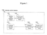
- FIG. 1 shows a block configuration of a vehicle control device according to the present invention.
- a vehicle control device 100 comprises a vehicle motion detection means 101, which detects the motion state of the host vehicle, and a travel path estimation means 102, which estimates a travel path based on the detected motion state.
- it comprises an obstacle detection means 103, which detects the position, speed and size of obstacles around the host vehicle.
- It further comprises an obstacle virtual linking means 104, which virtually links separated obstacles detected by the obstacle detection means 103 with each other based on the travel path estimated by the travel path estimation means 102, and a vehicle control determination means 105, which determines a control amount required to avoid obstacles based on the obtained positions of the obstacles.
- the travel path estimation means 102 is a means that estimates a travel path based on the motion state obtained from the vehicle motion detection means 101. In the present case, it performs estimation in accordance with a vehicle motion model based on steering angle ⁇ and vehicle speed V obtained from the vehicle motion detection means 101.
- a travel path point that is separated from the host vehicle by distance Lg is taken to be the front gaze position, and distance Lg the front gaze distance.
- the front gaze position is a position that is used in making determinations in the control for preventing road deviation of the host vehicle, which will be discussed in detail later, and is calculated through Equations 3 and 4 below, for example.
- Xp is the X-coordinate value of the front gaze position
- Zp the Z-coordinate value of the front gaze position.
- the coordinate system is a vehicle coordinate system where the center of gravity of a host vehicle 300 is taken to be the origin, the travel direction of the host vehicle 300 the Z-axis, the car width direction the X-axis, and the height direction the Y-axis.
- T is the forward gaze time, which is determined experimentally, and is typically set to a value of 1.0 to 3.0 [sec].
- ⁇ is the yaw angle of the host vehicle after the forward gaze time, and is calculated through Equation 5.
- Equation 6 is the yaw rate and is calculated through Equation 6 based on vehicle speed V and steering angle ⁇ . It is noted that, with respect to Equation 6, m is the weight of the host vehicle, 1 the wheel base, l f the length from the center of gravity of the vehicle to the front axle, l r the length from the center of gravity of the vehicle to the rear axle, K f the front wheel cornering power, K r the rear wheel cornering power, and n the steering ratio. These values are stored in memory.
- the obstacle detection in process step 500 is performed by the obstacle detection means 103. Based on ranging data obtained from the scanning range finder installed on the host vehicle, the obstacle detection means 103 detects the relative positions, relative speeds, and sizes of three-dimensional obstacles that are located near the road boundary. These three-dimensional objects located at the road boundary may be installed objects, such as sidewalk/road separating blocks, guard rails, walls, signs, traffic signal posts, etc., and, further, parked vehicles, etc.
- the scanning range finder such sensors as image sensors, TOF (Time of Flight) laser scanners, millimeter-wave radars, ultrasonic sensors, etc.
- Image sensors are typically used in a configuration comprising two or more synchronized units, where an environment within images of overlapping view fields is ranged based on the principles of triangulation.
- stereo image sensors comprising two image sensors are typically and often used.
- laser scanners For image sensors and laser scanners, light receiving elements that are sensitive to short wavelength ranges, such as CCD, CMOS, etc., are used, and they are characterized in that they have higher spatial resolution relative to millimeter-wave radars and ultrasonic sensors. Therefore, in the case of detecting three-dimensional objects at road boundaries for which complex forms are anticipated, it is preferable that laser scanners and image sensors comprising two or more units be used.
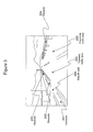
- Figure 3 and Figure 4 show an example where obstacles are detected by the obstacle detection means 103.
- Stereo image sensors are used as the scanning range finder.
- Figure 3 is an image of a traveled path as taken by the stereo image sensors installed on the inner side of the front window of the host vehicle.
- the host vehicle is traveling a straight path on the left side of a road comprising two traffic lanes, namely, a traveled traffic lane 205 and an oncoming traffic lane 206.
- Obstacles 201, 202 and 203 which are sidewalk/road separating blocks, are installed, in a mutually separated manner, at the road boundary of the travelled traffic lane 205.
- an obstacle 204 which is a guard rail, is installed at the road boundary of the oncoming traffic lane 206.
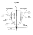
- Figure 4 shows an obstacle detection result detected by the scanning range finder with respect to a case where the host vehicle is travelling forward along the traveled traffic lane 205.
- the black dots are ranging data 120 and represent ranged positions of obstacles obtained from the scanning range finder.
- the bold arrow represents a travel path 310 of the host vehicle 300 as estimated by the travel path estimation means 102.
- the black dots enclosed by the dotted squares are ranging data 120 and represent detected obstacles.
- the obstacles 201, 202 and 203 are present on the left side of the travel path 310, and the obstacle 204 is present on the right side.
- the relative position and size of an obstacle may be estimated based on the distribution form of the ranging data 120. Since the scanning range finder outputs ranging data every pre-defined sampling time ⁇ t, relative speed may be estimated based on the relative position of the obstacle detected before sampling time ⁇ t.
- its "ID number,” “virtual linkee ID number,” “virtual link determination method type,” “virtual link position,” and “interpolation model parameter” are stored as attribute data.
- the attribute data is stored in the memory that the vehicle control device is equipped with, and is loaded as required. The attribute data is held until the relevant obstacle disappears from the view field of the scanning range finder, or for a predetermined period from when the obstacle is detected.
- the scanning range finder type may be any type so long as the sensor is capable of detecting obstacles in the traveled environment. Obstacles are thus detected in step 500.
- step 501 through step 505 a series of processes for virtual linking is performed. These processes are performed by the obstacle virtual linking means 104.
- step 501 a determination of virtual link subjects for performing virtual linking is made. For this method of determining link subjects, there are the following two methods.
- the first method is a method where, with respect to obstacles located in the left and right areas of a travel path, a pair of obstacles that are respectively located, in a separated manner, on a near side and a far side relative to the forward gaze distance is taken to be virtual link subjects.
- the virtual linking of a plurality of obstacles lined up along the travel direction becomes possible.
- the misalignment amount of the forward gaze position relative to the virtually linked area is detectable, deviation prevention control becomes possible. It is noted that misalignment amount and deviation prevention control will be described in connection with the vehicle control determination means 105 which is discussed later.
- the second method is a method where, with respect to obstacles located in the left and right areas of a travel path, a pair comprising an obstacle in the left area and an obstacle in the right area, which are located further than the forward gaze distance and for which the inter-obstacle gap relative with respect to the travel path is shortest, is taken to be virtual link subjects.
- a pair comprising an obstacle in the left area and an obstacle in the right area, which are located further than the forward gaze distance and for which the inter-obstacle gap relative with respect to the travel path is shortest, is taken to be virtual link subjects.
- the pair closest to the host vehicle is taken to be the subjects.
- the virtual linking of obstacles disposed in the travel direction and at an interval that is difficult to pass through becomes possible. Since the misalignment amount of the forward gaze position relative to the virtually linked area is detectable, deviation prevention control becomes possible.
- gaps between obstacles may be calculated by searching for, from among all combinations of ranging data belonging to the respective obstacles, a combination of ranging data that gives the shortest distance.
- the ranging data combination thus derived is stored in memory for later use in interpolating the gap position in step 504.
- Figure 5 and Figure 6 show examples of the above-discussed determination of virtual link subjects.
- Figure 5 shows an obstacle detection result for a case where the host vehicle 300 is traveling forward in the traveled traffic lane 205.
- the obstacle 201 which is located on the inside of a boundary circle 302 whose radius is the forward gaze distance Lg in the figure, and the obstacle 202, which is located on the outside, become virtual link subjects on the left side of the travel path 310 according to the first method. There are no virtual link subjects on the right side of the travel path 310 according to the first method.
- the obstacle 202 and the obstacle 204 which are a pair of obstacles with the shortest gap with respect to the travel path 310, become virtual link subjects according to the second method.
- Figure 6 shows an obstacle detection result for a case where the host vehicle 300 turns left from the traveled traffic lane 205 towards the branch road 200.
- the boundary circle 302 whose radius is the forward gaze distance Lg, there are no virtual link subjects according to the first method.
- the obstacle 201 and the obstacle 202 which are a pair of obstacles with the shortest distance with respect to the travel path 310, become virtual link subjects according to the second method.
- step 501 virtual link subjects are set through two methods. It is noted that, when selected as virtual link subjects, the pairs of ranging data stored in memory and used in calculating the shortest distance between obstacles are stored under the item "virtual link position" of the attribute data for the respective obstacles. The process of step 501 is thus concluded.
- obstacle link length Lth with respect to the obstacles of the pair selected as virtual link subjects is determined in step 502.
- Obstacle link length Lth is set based on the relationship between the host vehicle and the obstacles. The setting method thereof will be described using an example where the road shown in Figure 3 is traveled.
- function f is an increasing function with respect to speed.
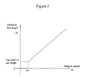
- Figure 7 is an example of a function that gives obstacle link length with respect to relative speed.
- the minimum of obstacle link length Lth is the car width or car length of the host vehicle and assuming a case of predetermined speed V 0 or greater, obstacle link length Lth is made longer in a linear fashion in accordance with relative speed Vr.
- obstacle link length Lth may also be determined in accordance with angle ⁇ formed between the arrangement of separated obstacles and the travel path of the host vehicle.
- angle ⁇ formed between the arrangement of separated obstacles and the travel path of the host vehicle.
- obstacle link length Lth is made to be a length corresponding to the car width, while making it be a length corresponding to the car length as angle ⁇ decreases.
- ⁇ d and ⁇ lw represent margins with respect to the car width and car length, respectively.
- L th l w + ⁇ ⁇ l w ⁇ sin ⁇ + d + ⁇ ⁇ d ⁇ cos ⁇
- obstacle link length Lth may also be determined using both relative speed Vr and angle ⁇ .
- Vr relative speed
- angle ⁇ it would be favorable to use Equation 9.
- L th ⁇ ⁇ l w + ⁇ ⁇ l w ⁇ sin ⁇ + d + ⁇ ⁇ d ⁇ cos ⁇ + 1 - ⁇ ⁇ f Vr
- obstacle link length Lth be calculated based on the greater of the values for relative speed Vr with respect to the two obstacles.
- obstacle link length Lth with respect to the virtual link subj ects according to the first method may be determined using Equation 7.
- obstacle link length Lth with respect to the virtual link subjects according to the second method be determined using Equation 8 or Equation 9. It is noted that the setting of obstacle link length Lth is not limited to the method mentioned above, and may instead be set by other methods. The setting of the virtual link length in step 502 is thus concluded.
- step 503 with respect to all the virtual link subjects determined in step 501, a determination on carrying out virtual linking is sequentially performed based on obstacle link length Lth determined in step 502. If the gap between two obstacles that are virtual link subjects is shorter than obstacle link length Lth, a determination is made to perform a virtual linking process. On the other hand, if the gap between two obstacles is longer than obstacle link length Lth, it is determined that virtual linking is not to be performed.
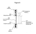
- Figure 8 is a figure showing, in an enlarged manner, virtual link subjects determined by the first method and that are located in the left area of the travel path 310 in Figure 5 .
- the obstacle 201 and the obstacle 202 are virtual link subjects.
- Obstacle link length Lth with respect to these two obstacles may be calculated by means of a function (relation) of obstacle link length Lth with respect to relative speed Vr such as that shown in Figure 7 .
- Vr relative speed
- Figure 9 shows, in an enlarged manner, the obstacle 202 and the obstacle 204 which are virtual link subjects determined by the second method.
- Obstacle link length Lth is calculated based on Equation 9 using angle ⁇ 233 formed between the travel path 310 and line 230 of the shortest distance connecting virtual link position 231 of the obstacle 202 and virtual link position 232 of the obstacle 204, and relative speed Vr.
- calculated obstacle link length 220 is shorter than gap 222 between the two obstacles, it is determined that linking is not to be performed with respect to these two obstacles.
- Figure 10 shows, in an enlarged manner, an example where the host vehicle turns towards virtual link subj ects determined by the first method with respect to Figure 6 .
- the obstacle 201 and the obstacle 202 are virtual link subjects.
- Obstacle link length Lth is calculated based on Equation 9 using angle ⁇ 233 formed between the travel path 310 and line 230 of the shortest distance connecting virtual link position 232 of the obstacle 201 and virtual link position 231 of the obstacle 202, and relative speed Vr.
- calculated obstacle link length 220 is longer than gap 221 between the two obstacles, it is determined that these two obstacles are to be virtually linked.
- step 503. a determination as to whether or not virtual linking is to be performed is made in step 503. It is noted that the ID number of the other obstacle is stored under the item "virtual linkee ID number" of the attribute data of the two obstacles for which it has been determined that virtual linking is to be performed. In addition, which of the first and second methods it has been determined that virtual linking is to be performed by is stored under the item "virtual link determination method type" of the attribute data. The process in step 503 is thus concluded.
- step 504 a gap position interpolation process is performed with respect to the pair comprising the two obstacles for which it has been determined in step 503 that virtual linking is to be performed.
- linear interpolation it is preferable that linear interpolation be performed using the pair of ranging data stored under the item "virtual link position" of the attribute data of the respective obstacles stored in memory.
- interpolation line 230 is derived through linear interpolation based on virtual link position 231 of the obstacle 201 and virtual link position 232 of the obstacle 202. Parameters of the derived interpolation line are stored under "interpolation model parameter" of the attribute data. The parameters are used in the avoidance control subject search in step 505.
- the obstacles virtually linked by the obstacle virtual linking means 104 and the obstacles detected by the obstacle detection means 103 are tracked by estimating their positions after sampling time ⁇ t based on the measured relative positions and relative speeds. It is preferable that obstacles that have been virtually linked in the past be tracked with the virtually linked state sustained. In particular, since obstacles virtually linked by the first method are located at positions near the front gaze position, it is preferable that, once virtually linked, it not be cancelled. In addition, it is preferable that obstacles virtually linked by the second method be cancelled only when it is subsequently determined that virtual linking is not to be performed by the second method.
- step 505 a search is performed as to whether or not there exists a control subject for which collision is to be avoided.
- the processes of this step 505, and of subsequent step 506 and step 507, are executed at the vehicle control determination means 105.
- the avoidance control subject search in step 505 is performed every sampling period ⁇ t, and a search is performed based on the items "relative position,” “size,” and “gradient” of the attribute data of the obstacles stored in memory, and on the forward gaze position.
- the located area of an obstacle is derived based on "relative position,” “size,” and “gradient.” If the forward gaze position falls within a predetermined range of this located area, this obstacle is taken to be an avoidance control subject.
- step 506 based on the position information of the avoidance control subject found in step 505, target yaw moment M r for avoiding the obstacle is generated.
- Equation 10 is an example of an equation for calculating this target yaw moment M r .
- M r ⁇ K 1 ⁇ ⁇ + K 2 ⁇ d ⁇ dt ⁇ > 0 0 ⁇ ⁇ 0
- K 1 and K 2 represent control gain, and ⁇ the misalignment amount between the located area of an obstacle and the forward gaze position. It is noted that misalignment amount ⁇ is positive when the forward gaze position goes beyond the obstacle, and a yaw moment is generated only when misalignment amount ⁇ is positive. In addition, with respect to the yaw moment, it is assumed that the anticlockwise direction is positive.
- step 507 vehicle control is performed based on the target yaw moment generated in step 506.
- a braking device that is capable of independently controlling the braking forces on the left and right wheels of the front and rear wheels.
- the braking device may also be a brake that utilizes fluid pressure, or a brake that electrically causes a braking action.
- a yaw moment may also be generated by adjusting the rotation of the steering shaft.
- Figure 11 and Figure 12 show an example where vehicle control is performed.
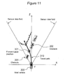
- Figure 11 shows a distribution of ranging data with respect to a case where one proceeds towards the branch road on the left from the host vehicle position 300.
- Figure 12 shows, in an enlarged manner, the vicinity of the forward gaze position 301 shown in Figure 11 .
- the obstacle 201 and the obstacle 202 are a pair of virtually linked obstacles that have been found as avoidance control subjects in step 505. It is assumed that interpolation line 351 has been derived through the gap position interpolation process in step 504.
- step 507 vehicle control for avoiding the virtually linked obstacles is executed based on this calculated target yaw moment.
- step 500 to step 507 are repeatedly executed at sampling period ⁇ t, and control for avoiding collision with obstacles is realized.
- the control timing for obstacle avoidance control of the host vehicle may be quickened by performing calculations based not on the located area of the obstacle, but instead on a position that is closer to the host vehicle from the obstacle by a predetermined length.
- obstacle avoidance control that takes the displacement of the obstacle into account becomes possible by lengthening/shortening the above-mentioned predetermined length depending on the relative speed of the obstacle, for example.
Landscapes
- Engineering & Computer Science (AREA)
- Automation & Control Theory (AREA)
- Transportation (AREA)
- Mechanical Engineering (AREA)
- Physics & Mathematics (AREA)
- General Physics & Mathematics (AREA)
- Mathematical Physics (AREA)
- Control Of Driving Devices And Active Controlling Of Vehicle (AREA)
- Traffic Control Systems (AREA)
Abstract
Description
- The present invention is a vehicle control device and vehicle control method wherein, using an obstacle detection device mounted on a vehicle, a three-dimensional object within a travel area is detected and collision with that three-dimensional object is avoided.
- Technical developments related to ASV (Advanced Safety Vehicle) wherein warnings are given to drivers and operation assistance is provided to ensure safe driving of vehicles have been underway. In particular, in order to prevent vehicles from deviating from roads, three-dimensional objects representing road boundaries, such as sidewalk/road separating blocks, guard rails, hedges, etc., or traffic lanes, etc., need to be detected, and the host vehicle needs to be controlled in accordance with the detection result. As for three-dimensional objects representing road boundaries, they are separated and lined up at various intervals as can be understood from the fact that, by way of example, there are those that are lined up at intervals that allow entry by vehicles, as in entrances to parking lots, or branch roads, and there are also those that are lined up at intervals that only allow entry by pedestrians.
- In preventing deviation from roads, continuous deviation prevention control is performed with respect to separated three-dimensional objects. However, an arrangement needs to be made such that deviation prevention control is not performed when entering parking lots or branch roads.
- With respect to boundary position detection, by way of example, there is disclosed in Patent Document 1 a technique for detecting a three-dimensional object representing a traffic lane or road boundary based on an image or distance measurement data (ranging data) obtained from a camera or laser scanner mounted on a vehicle.
- In addition, with respect to deviation prevention control, by way of example, there is disclosed in Patent Document 2 a technique for preventing, where there is a possibility that the host vehicle might deviate from the traveled traffic lane, the host vehicle from deviating from the traveled traffic lane by imparting to the host vehicle a yaw moment by controlling the braking force on the wheels. In addition, by way of example, there is disclosed in Patent Document 3 a technique for preventing deviation from a road by adjusting the yaw moment imparted to the host vehicle in accordance with the position of an obstacle at the shoulder, such as a parked vehicle, etc., that exists in a travel area.
-
- Patent Document 1:
JP Patent Application Publication No. 11-213138 A (1999 - Patent Document 2:
JP Patent Application Publication No. 2000-33 860 A - Patent Document 3:
JP Patent Application Publication No. 2005-324782 A - With the related art mentioned above, a plurality of three-dimensional objects representing a road boundary and mutually separated in the travel direction are determined as being a single object. Thus, by way of example, if a continuous road deviation operation were to be performed near a road boundary where sidewalk/road separating blocks are discontinuously lined up, there would be concerns that discontinuity may occur, such as control input weakening, etc., at a gap portion of the sidewalk/road separating blocks. There is a problem in that, when discontinuity occurs in the control input, unwanted vehicle behavior occurs, leading to compromised safety, and increased discomfort with respect to operation assistance.
- The present invention is made with a view to solving the problems mentioned above, and an object thereof is to provide a vehicle control device and vehicle control method that enable stable road deviation prevention by virtually linking obstacles with each other based on the relationship between a plurality of mutually separated obstacles and the host vehicle.
- With a view to solving the problems mentioned above, the present invention is a vehicle control device that controls vehicle behavior in such a manner that, when a host vehicle approaches an obstacle, the host vehicle does not come into contact with the obstacle, comprising: obstacle detection means that detects the size of an obstacle present around the host vehicle, as well as its relative position and relative speed with respect to the host vehicle; vehicle motion detection means that detects a motion state of the host vehicle; and obstacle virtual linking means that virtually links, and recognizes as one obstacle, a plurality of obstacles detected by the obstacle detection means, wherein the obstacle virtual linking means determines and executes the linking of the plurality of obstacles based on relative position and magnitude of relative speed.
- In addition to the features above, the obstacle virtual linking means comprises obstacle link length setting means that sets an obstacle link length which serves as a determination criterion for linking obstacles with each other, wherein the linking of the plurality of obstacles is executed when a gap between the plurality of obstacles is shorter than the obstacle link length. Further, the obstacle virtual linking means comprises travel path estimation means that estimates a travel path of the host vehicle based on the motion state detected from the vehicle motion detection means, wherein a pair of obstacles to be virtually linked is selected in accordance with the estimated travel path and the relative positions of the obstacles detected by the obstacle detection means. Further, the obstacle virtual linking means selects, from each of a left area and a right area relative to the travel path, a pair comprising an obstacle that is further from the host vehicle than a predetermined distance and an obstacle that is closer than the predetermined distance, and virtually links them as a pair of obstacles.
- It further comprises vehicle control determination means that calculates a yaw moment control amount required for avoiding an obstacle based on the relationship between the obstacle and the host vehicle obtained by the obstacle detection means and the obstacle virtual linking means, wherein, if the obstacle or the virtually linked obstacle is located within the predetermined distance from the host vehicle along the travel path, the vehicle control determination means determines the obstacle to be an avoidance control subject and calculates a yaw moment control amount required for avoiding the avoidance control subject.
- In addition, it is a vehicle control method that controls vehicle behavior in such a manner that, when a host vehicle approaches an obstacle, the host vehicle does not come into contact with the obstacle, wherein the size of an obstacle that is present around the host vehicle, as well as its relative position and relative speed with respect to the host vehicle are detected, a motion state of the host vehicle is detected, a detected plurality of obstacles are virtually linked and recognized as one obstacle, and the linking of the plurality of obstacles is determined and executed based on the detected relative position and the magnitude of the relative speed.
- With respect to obstacles lined up and separated at varying intervals, by performing, as deemed appropriate, the possibility of virtually linking two obstacles based on their relationship with the host vehicle, it is possible to, with respect to road deviation prevention control, prevent discontinuity from occurring in the control input to cause unstable vehicle behavior, and to realize stable and comfortable driving.
-
-
Figure 1 shows a block configuration of a vehicle control device according to an embodiment. -
Figure 2 shows a flowchart of a vehicle control method according to an embodiment. -
Figure 3 shows an example of a travel scene to which a device or method according to an embodiment is applied. -
Figure 4 shows a distribution of ranging data of obstacles obtained from a scanning range finder when the travel scene inFigure 3 is traveled. -
Figure 5 shows a determination example for virtual link subjects when traveling straight in the travelled traffic lane with respect to the travel scene inFigure 3 . -
Figure 6 shows a determination example for virtual link subjects when turning towards the branch road in the travel scene inFigure 3 . -
Figure 7 shows an example of a function that gives obstacle link length with respect to relative speed. -
Figure 8 shows an enlarged view of virtual link subjects selected through a first method with respect toFigure 5 . -
Figure 9 shows an enlarged view of virtual link subjects selected through a second method with respect toFigure 5 . -
Figure 10 shows, in an enlarged manner, an example where the host vehicle turns towards virtual link subjects determined through the first method with respect toFigure 6 . -
Figure 11 shows a distribution of ranging data in a case where one proceeds from the host vehicle position towards a branch road on the left. -
Figure 12 shows, in an enlarged manner, the vicinity offorward gaze position 301 shown inFigure 11 and misalignment amount ε. - Best modes for carrying out the present invention are described below based on the drawings. However, the present invention may be carried out in numerous and varying embodiments, and is not to be construed as being limited to the disclosure of the present modes.
- Embodiments of the present invention are described in detail below with reference to the drawings.
-
Figure 1 shows a block configuration of a vehicle control device according to the present invention. Avehicle control device 100 comprises a vehicle motion detection means 101, which detects the motion state of the host vehicle, and a travel path estimation means 102, which estimates a travel path based on the detected motion state. In addition, it comprises an obstacle detection means 103, which detects the position, speed and size of obstacles around the host vehicle. It further comprises an obstacle virtual linking means 104, which virtually links separated obstacles detected by the obstacle detection means 103 with each other based on the travel path estimated by the travel path estimation means 102, and a vehicle control determination means 105, which determines a control amount required to avoid obstacles based on the obtained positions of the obstacles. - Next, the vehicle motion detection means 101 and the travel path estimation means 102 will be described. The vehicle motion detection means 101 is a means that detects a physical quantity related to vehicle motion. It comprises wheel speed sensors, which detect rotation speeds ωi (i = fl, fr, rl, rr) of the four wheels at the front/rear/left/right of the host vehicle, and a steering angle sensor, which detects steering angle δ of the steering wheel. It is noted that ωfl indicates the rotation speed of the front wheel on the left, ωfr the rotation speed of the front wheel on the right, ωrl the rotation speed of the rear wheel on the left, and ωrr the rotation speed of the rear wheel on the left.
- In addition, turning signal indicators that detect a turning signal operation by the driver are also included. The use of
Equation 1 or Equation 2 below is favorable for calculating vehicle speed V of the host vehicle. It is noted that the tire radius is denoted rw. - In the case of front-wheel drive,

- In the case of rear-wheel drive,

- The travel path estimation means 102 is a means that estimates a travel path based on the motion state obtained from the vehicle motion detection means 101. In the present case, it performs estimation in accordance with a vehicle motion model based on steering angle δ and vehicle speed V obtained from the vehicle motion detection means 101.
- It is assumed that the zone for estimating a travel path is within the detection range of the scanning range finder. A travel path point that is separated from the host vehicle by distance Lg is taken to be the front gaze position, and distance Lg the front gaze distance. The front gaze position is a position that is used in making determinations in the control for preventing road deviation of the host vehicle, which will be discussed in detail later, and is calculated through Equations 3 and 4 below, for example.


- Here, Xp is the X-coordinate value of the front gaze position, and Zp the Z-coordinate value of the front gaze position. Here, as shown in
Figure 4 , the coordinate system is a vehicle coordinate system where the center of gravity of ahost vehicle 300 is taken to be the origin, the travel direction of thehost vehicle 300 the Z-axis, the car width direction the X-axis, and the height direction the Y-axis. In addition, T is the forward gaze time, which is determined experimentally, and is typically set to a value of 1.0 to 3.0 [sec]. Φ is the yaw angle of the host vehicle after the forward gaze time, and is calculated through Equation 5. r is the yaw rate and is calculated through Equation 6 based on vehicle speed V and steering angle δ. It is noted that, with respect to Equation 6, m is the weight of the host vehicle, 1 the wheel base, lf the length from the center of gravity of the vehicle to the front axle, lr the length from the center of gravity of the vehicle to the rear axle, Kf the front wheel cornering power, Kr the rear wheel cornering power, and n the steering ratio. These values are stored in memory. - Next, the obstacle detection means 103, the obstacle virtual linking means 104, and the vehicle control determination means 105 will be described in accordance with the process flow of the embodiment shown in
Figure 2 . - The obstacle detection in
process step 500 is performed by the obstacle detection means 103. Based on ranging data obtained from the scanning range finder installed on the host vehicle, the obstacle detection means 103 detects the relative positions, relative speeds, and sizes of three-dimensional obstacles that are located near the road boundary. These three-dimensional objects located at the road boundary may be installed objects, such as sidewalk/road separating blocks, guard rails, walls, signs, traffic signal posts, etc., and, further, parked vehicles, etc. - In addition, for the scanning range finder, such sensors as image sensors, TOF (Time of Flight) laser scanners, millimeter-wave radars, ultrasonic sensors, etc., are typically used. Image sensors are typically used in a configuration comprising two or more synchronized units, where an environment within images of overlapping view fields is ranged based on the principles of triangulation. By way of example, stereo image sensors comprising two image sensors are typically and often used.
- For image sensors and laser scanners, light receiving elements that are sensitive to short wavelength ranges, such as CCD, CMOS, etc., are used, and they are characterized in that they have higher spatial resolution relative to millimeter-wave radars and ultrasonic sensors. Therefore, in the case of detecting three-dimensional objects at road boundaries for which complex forms are anticipated, it is preferable that laser scanners and image sensors comprising two or more units be used.
-
Figure 3 andFigure 4 show an example where obstacles are detected by the obstacle detection means 103. Stereo image sensors are used as the scanning range finder.Figure 3 is an image of a traveled path as taken by the stereo image sensors installed on the inner side of the front window of the host vehicle. The host vehicle is traveling a straight path on the left side of a road comprising two traffic lanes, namely, a traveledtraffic lane 205 and an oncomingtraffic lane 206.Obstacles traffic lane 205. In addition, anobstacle 204, which is a guard rail, is installed at the road boundary of the oncomingtraffic lane 206. There is aleftward branch road 200 between theobstacle 201 and theobstacle 202. -
Figure 4 shows an obstacle detection result detected by the scanning range finder with respect to a case where the host vehicle is travelling forward along the traveledtraffic lane 205. InFigure 4 , the black dots are rangingdata 120 and represent ranged positions of obstacles obtained from the scanning range finder. The bold arrow represents atravel path 310 of thehost vehicle 300 as estimated by the travel path estimation means 102. The black dots enclosed by the dotted squares are rangingdata 120 and represent detected obstacles. Here, it is indicated that theobstacles travel path 310, and theobstacle 204 is present on the right side. - The relative position and size of an obstacle may be estimated based on the distribution form of the ranging
data 120. Since the scanning range finder outputs ranging data every pre-defined sampling time Δt, relative speed may be estimated based on the relative position of the obstacle detected before sampling time Δt. In addition to the "relative position," "relative speed," and "size" of a detected obstacle, its "ID number," "virtual linkee ID number," "virtual link determination method type," "virtual link position," and "interpolation model parameter" are stored as attribute data. The attribute data is stored in the memory that the vehicle control device is equipped with, and is loaded as required. The attribute data is held until the relevant obstacle disappears from the view field of the scanning range finder, or for a predetermined period from when the obstacle is detected. - It is noted that since the present invention is by no means limited by the scanning range finder type, the scanning range finder type may be any type so long as the sensor is capable of detecting obstacles in the traveled environment. Obstacles are thus detected in
step 500. - Next, in
step 501 throughstep 505, a series of processes for virtual linking is performed. These processes are performed by the obstacle virtual linking means 104. First, instep 501, a determination of virtual link subjects for performing virtual linking is made. For this method of determining link subjects, there are the following two methods. - The first method is a method where, with respect to obstacles located in the left and right areas of a travel path, a pair of obstacles that are respectively located, in a separated manner, on a near side and a far side relative to the forward gaze distance is taken to be virtual link subjects. Thus, the virtual linking of a plurality of obstacles lined up along the travel direction becomes possible. Even if the host vehicle were to suddenly change its travel direction, since the misalignment amount of the forward gaze position relative to the virtually linked area is detectable, deviation prevention control becomes possible. It is noted that misalignment amount and deviation prevention control will be described in connection with the vehicle control determination means 105 which is discussed later.
- The second method is a method where, with respect to obstacles located in the left and right areas of a travel path, a pair comprising an obstacle in the left area and an obstacle in the right area, which are located further than the forward gaze distance and for which the inter-obstacle gap relative with respect to the travel path is shortest, is taken to be virtual link subjects. Here, if there are a plurality of pairs with narrow gaps, the pair closest to the host vehicle is taken to be the subjects. Thus, the virtual linking of obstacles disposed in the travel direction and at an interval that is difficult to pass through becomes possible. Since the misalignment amount of the forward gaze position relative to the virtually linked area is detectable, deviation prevention control becomes possible.
- With respect to the two methods above, gaps between obstacles may be calculated by searching for, from among all combinations of ranging data belonging to the respective obstacles, a combination of ranging data that gives the shortest distance. The ranging data combination thus derived is stored in memory for later use in interpolating the gap position in
step 504. -
Figure 5 andFigure 6 show examples of the above-discussed determination of virtual link subjects.Figure 5 shows an obstacle detection result for a case where thehost vehicle 300 is traveling forward in the traveledtraffic lane 205. Theobstacle 201, which is located on the inside of aboundary circle 302 whose radius is the forward gaze distance Lg in the figure, and theobstacle 202, which is located on the outside, become virtual link subjects on the left side of thetravel path 310 according to the first method. There are no virtual link subjects on the right side of thetravel path 310 according to the first method. In addition, on the outside of theboundary circle 302, theobstacle 202 and theobstacle 204, which are a pair of obstacles with the shortest gap with respect to thetravel path 310, become virtual link subjects according to the second method. -
Figure 6 , as indicated by the left-turningtravel path 310, shows an obstacle detection result for a case where thehost vehicle 300 turns left from the traveledtraffic lane 205 towards thebranch road 200. Here, since there are no obstacles on the inside of theboundary circle 302 whose radius is the forward gaze distance Lg, there are no virtual link subjects according to the first method. In addition, on the outside of theboundary circle 302, theobstacle 201 and theobstacle 202, which are a pair of obstacles with the shortest distance with respect to thetravel path 310, become virtual link subjects according to the second method. - As demonstrated through the two examples above, in
step 501, virtual link subjects are set through two methods. It is noted that, when selected as virtual link subjects, the pairs of ranging data stored in memory and used in calculating the shortest distance between obstacles are stored under the item "virtual link position" of the attribute data for the respective obstacles. The process ofstep 501 is thus concluded. - Next, obstacle link length Lth with respect to the obstacles of the pair selected as virtual link subjects is determined in
step 502. Obstacle link length Lth is set based on the relationship between the host vehicle and the obstacles. The setting method thereof will be described using an example where the road shown inFigure 3 is traveled. - By way of example, if, due to an erroneous handle maneuver by the driver while traveling at a high speed, the host vehicle were to turn towards the
branch road 200, it is preferable that theobstacle 201 and theobstacle 202 be virtually linked and obstacle avoidance control be performed before the host vehicle enters thebranch road 200. In contrast, if the host vehicle were to turn towards thebranch road 200 due to a handle maneuver by the driver while traveling at a low speed, it is preferable that theobstacle 201 and theobstacle 202 not be virtually linked so as not to obstruct entry by the host vehicle. As in the examples above, in the determination for virtually linking separated obstacles, relative speed Vr between the vehicle and the obstacle becomes important. As such, it is preferable that obstacle link length Lth be set in accordance with relative speed Vr between the vehicle and the obstacle. Specifically, it is preferable that it be determined in accordance with Equation 7 below.
- Here, function f is an increasing function with respect to speed.
-
Figure 7 is an example of a function that gives obstacle link length with respect to relative speed. Here, assuming the minimum of obstacle link length Lth is the car width or car length of the host vehicle and assuming a case of predetermined speed V0 or greater, obstacle link length Lth is made longer in a linear fashion in accordance with relative speed Vr. - In addition, besides relative speed, obstacle link length Lth may also be determined in accordance with angle α formed between the arrangement of separated obstacles and the travel path of the host vehicle. By way of example, if a gap between separated obstacles is to be passed through straight, that is, if angle α is π/2, obstacle link length Lth is made to be a length corresponding to the car width, while making it be a length corresponding to the car length as angle α decreases. Assuming the car width of the host vehicle is d and its car length lw, the use of Equation 8 would be favorable, for example. Here, Δd and Δlw represent margins with respect to the car width and car length, respectively.

- In addition, obstacle link length Lth may also be determined using both relative speed Vr and angle α. By way of example, it would be favorable to use Equation 9.

- where β = (2/π) α.
- When angle α is sufficiently small relative to π/2, the obstacle link length commensurate with the relative speed is given priority. When angle α is close to π/2, the obstacle link length commensurate with the angle formed between two obstacles and the travel path is given priority. In addition, it is preferable that obstacle link length Lth be calculated based on the greater of the values for relative speed Vr with respect to the two obstacles.
- With respect to the virtual link subjects determined in
step 501, obstacle link length Lth with respect to the virtual link subj ects according to the first method may be determined using Equation 7. In addition, it is preferable that obstacle link length Lth with respect to the virtual link subjects according to the second method be determined using Equation 8 or Equation 9. It is noted that the setting of obstacle link length Lth is not limited to the method mentioned above, and may instead be set by other methods. The setting of the virtual link length instep 502 is thus concluded. - Next, in
step 503, with respect to all the virtual link subjects determined instep 501, a determination on carrying out virtual linking is sequentially performed based on obstacle link length Lth determined instep 502. If the gap between two obstacles that are virtual link subjects is shorter than obstacle link length Lth, a determination is made to perform a virtual linking process. On the other hand, if the gap between two obstacles is longer than obstacle link length Lth, it is determined that virtual linking is not to be performed. - Using
Figure 8 ,Figure 9 , andFigure 10 , examples of procedures for determining whether or not to perform virtual linking will be described.Figure 8 is a figure showing, in an enlarged manner, virtual link subjects determined by the first method and that are located in the left area of thetravel path 310 inFigure 5 . Theobstacle 201 and theobstacle 202 are virtual link subjects. Obstacle link length Lth with respect to these two obstacles may be calculated by means of a function (relation) of obstacle link length Lth with respect to relative speed Vr such as that shown inFigure 7 . As shown inFigure 8 , since determinedobstacle link length 220 is longer thangap 221 of the two obstacles, in such a case, it is determined that these two obstacles are to be virtually linked. - Next, an example of a link determination for virtual link subjects determined by the second method will be described.
Figure 9 shows, in an enlarged manner, theobstacle 202 and theobstacle 204 which are virtual link subjects determined by the second method. Obstacle link length Lth is calculated based on Equation 9 usingangle α 233 formed between thetravel path 310 andline 230 of the shortest distance connectingvirtual link position 231 of theobstacle 202 andvirtual link position 232 of theobstacle 204, and relative speed Vr. As shown inFigure 9 , since calculatedobstacle link length 220 is shorter thangap 222 between the two obstacles, it is determined that linking is not to be performed with respect to these two obstacles. -
Figure 10 shows, in an enlarged manner, an example where the host vehicle turns towards virtual link subj ects determined by the first method with respect toFigure 6 . Here, theobstacle 201 and theobstacle 202 are virtual link subjects. Obstacle link length Lth is calculated based on Equation 9 usingangle α 233 formed between thetravel path 310 andline 230 of the shortest distance connectingvirtual link position 232 of theobstacle 201 andvirtual link position 231 of theobstacle 202, and relative speed Vr. In the example shown inFigure 10 , since calculatedobstacle link length 220 is longer thangap 221 between the two obstacles, it is determined that these two obstacles are to be virtually linked. - As demonstrated through the three examples above, a determination as to whether or not virtual linking is to be performed is made in
step 503. It is noted that the ID number of the other obstacle is stored under the item "virtual linkee ID number" of the attribute data of the two obstacles for which it has been determined that virtual linking is to be performed. In addition, which of the first and second methods it has been determined that virtual linking is to be performed by is stored under the item "virtual link determination method type" of the attribute data. The process instep 503 is thus concluded. - Next, in
step 504, a gap position interpolation process is performed with respect to the pair comprising the two obstacles for which it has been determined instep 503 that virtual linking is to be performed. With respect to the method of interpolation, it is preferable that linear interpolation be performed using the pair of ranging data stored under the item "virtual link position" of the attribute data of the respective obstacles stored in memory. By way of example, inFigure 8 ,interpolation line 230 is derived through linear interpolation based onvirtual link position 231 of theobstacle 201 andvirtual link position 232 of theobstacle 202. Parameters of the derived interpolation line are stored under "interpolation model parameter" of the attribute data. The parameters are used in the avoidance control subject search instep 505. - Thus, it is possible to virtually link separated obstacles by means of the obstacle virtual linking means 104 in accordance with the travel state of the host vehicle. It is noted that the obstacles virtually linked by the obstacle virtual linking means 104 and the obstacles detected by the obstacle detection means 103 are tracked by estimating their positions after sampling time Δt based on the measured relative positions and relative speeds. It is preferable that obstacles that have been virtually linked in the past be tracked with the virtually linked state sustained. In particular, since obstacles virtually linked by the first method are located at positions near the front gaze position, it is preferable that, once virtually linked, it not be cancelled. In addition, it is preferable that obstacles virtually linked by the second method be cancelled only when it is subsequently determined that virtual linking is not to be performed by the second method.
- Next, in
step 505, a search is performed as to whether or not there exists a control subject for which collision is to be avoided. The processes of thisstep 505, and ofsubsequent step 506 and step 507, are executed at the vehicle control determination means 105. The avoidance control subject search instep 505 is performed every sampling period Δt, and a search is performed based on the items "relative position," "size," and "gradient" of the attribute data of the obstacles stored in memory, and on the forward gaze position. The located area of an obstacle is derived based on "relative position," "size," and "gradient." If the forward gaze position falls within a predetermined range of this located area, this obstacle is taken to be an avoidance control subject. It is noted that if an ID number is stored under the item "virtual linkee ID number" of the attribute data, a search is performed with the attribute data of the virtual linkee included as well. If virtually linked, a position between the obstacles is taken into consideration as an area where an obstacle is located using "interpolation model parameter." - Next, in
step 506, based on the position information of the avoidance control subject found instep 505, target yaw moment Mr for avoiding the obstacle is generated. Equation 10 is an example of an equation for calculating this target yaw moment Mr.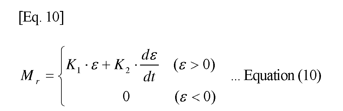
- Here, K1 and K2 represent control gain, and ε the misalignment amount between the located area of an obstacle and the forward gaze position. It is noted that misalignment amount ε is positive when the forward gaze position goes beyond the obstacle, and a yaw moment is generated only when misalignment amount ε is positive. In addition, with respect to the yaw moment, it is assumed that the anticlockwise direction is positive.
- Finally, in
step 507, vehicle control is performed based on the target yaw moment generated instep 506. In order to generate a yaw moment with respect to the vehicle, by way of example, there may be provided a braking device that is capable of independently controlling the braking forces on the left and right wheels of the front and rear wheels. The braking device may also be a brake that utilizes fluid pressure, or a brake that electrically causes a braking action. In addition, a yaw moment may also be generated by adjusting the rotation of the steering shaft. -
Figure 11 andFigure 12 show an example where vehicle control is performed.Figure 11 shows a distribution of ranging data with respect to a case where one proceeds towards the branch road on the left from thehost vehicle position 300.Figure 12 shows, in an enlarged manner, the vicinity of theforward gaze position 301 shown inFigure 11 . Theobstacle 201 and theobstacle 202 are a pair of virtually linked obstacles that have been found as avoidance control subjects instep 505. It is assumed thatinterpolation line 351 has been derived through the gap position interpolation process instep 504. - As shown in
Figure 12 , since theforward gaze position 301 is at a position beyondinterpolation line 351 from thehost vehicle 300,misalignment amount ε 350 assumes a positive value. As a result, a target yaw moment is calculated through Equation 10 instep 506. Instep 507, vehicle control for avoiding the virtually linked obstacles is executed based on this calculated target yaw moment. - The processes above from
step 500 to step 507 are repeatedly executed at sampling period Δt, and control for avoiding collision with obstacles is realized. - Embodiments of the present invention have been described above. However, modes for carrying out the present invention are by no means limited to the embodiments discussed above, and various modified embodiments are possible. By way of example, if a blinker instruction is given by the driver, priority may be accorded to the intention of the driver such that virtual linking is not performed. In addition, entry by the host vehicle may be obstructed regardless of vehicle speed by virtually linking obstacles based on entrance position information for roads that bar entry by vehicles, such as one-way exits, entrances to pedestrian roads, etc., obtained from a navigation system installed on the host vehicle.
- In addition, with respect to the calculation of misalignment amount ε, the control timing for obstacle avoidance control of the host vehicle may be quickened by performing calculations based not on the located area of the obstacle, but instead on a position that is closer to the host vehicle from the obstacle by a predetermined length. In this case, obstacle avoidance control that takes the displacement of the obstacle into account becomes possible by lengthening/shortening the above-mentioned predetermined length depending on the relative speed of the obstacle, for example.
-
- 100:
- vehicle control device,
- 101:
- vehicle motion detection means,
- 102:
- travel path estimation means,
- 103:
- obstacle detection means,
- 104:
- obstacle virtual linking means,
- 105:
- vehicle control determination means,
- 120:
- ranging data,
- 200:
- branch road,
- 201-204:
- obstacle,
- 205:
- traveled traffic lane,
- 206:
- oncoming traffic lane,
- 220:
- obstacle link length Lth,
- 221:
- gap between
obstacle 201 andobstacle 202, - 222:
- gap between
obstacle 202 andobstacle 204, - 230:
- line of shortest distance,
- 231, 232:
- virtual link position,
- 300:
- host vehicle,
- 301:
- forward gaze position,
- 302:
- boundary circle,
- 310:
- travel path,
- 350:
- misalignment amount ε,
- 351:
- interpolation line
Claims (20)
- A vehicle control device that controls vehicle behavior in such a manner that, when a host vehicle approaches an obstacle, the host vehicle does not come into contact with the obstacle, the vehicle control device comprising:obstacle detection means that detects the size of an obstacle present around the host vehicle, as well as its relative position and relative speed with respect to the host vehicle;vehicle motion detection means that detects a motion state of the host vehicle; andobstacle virtual linking means that virtually links, and recognizes as one obstacle, a plurality of obstacles detected by the obstacle detection means, whereinthe obstacle virtual linking means determines and executes the linking of the plurality of obstacles based on the relative position and the magnitude of the relative speed.
- The vehicle control device according to claim 1, wherein
the obstacle virtual linking means comprises obstacle link length setting means that sets an obstacle link length, which serves as a determination criterion for linking obstacles with each other, and
the linking of the plurality of obstacles is executed when a gap between the plurality of obstacles is shorter than the obstacle link length. - The vehicle control device according to claim 2, wherein the obstacle virtual linking means determines the obstacle link length based on the relative speed of an obstacle with respect to the host vehicle and the size of the host vehicle.
- The vehicle control device according to any one of claims 1 to 3, wherein
the obstacle virtual linking means comprises travel path estimation means that estimates a travel path of the host vehicle based on the motion state detected from the vehicle motion detection means, and
a pair of obstacles to be virtually linked is selected in accordance with the estimated travel path and the relative positions of the obstacles detected by the obstacle detection means. - The vehicle control device according to any one of claims 1 to 4, wherein the obstacle virtual linking means selects, from each of a left area and a right area relative to the travel path, a pair comprising an obstacle that is further from the host vehicle than a predetermined distance and an obstacle that is closer than the predetermined distance, and virtually links them as a pair of obstacles.
- The vehicle control device according to any one of claims 1 to 5, wherein the obstacle virtual linking means selects, from among a plurality of obstacles that are further from the host vehicle than a predetermined distance, a pair of obstacles whose distance between an obstacle belonging to a left area relative to the travel path and an obstacle belonging to a right area is shortest, and virtually links them as a pair of obstacles.
- The vehicle control device according to any one of claims 1 to 6, further comprising vehicle control determination means that calculates a yaw moment control amount required for avoiding an obstacle based on the relationship between the obstacle and the host vehicle obtained by the obstacle detection means and the obstacle virtual linking means.
- The vehicle control device according to claim 7, wherein, if the obstacle or the virtually linked obstacle is located within the predetermined distance from the host vehicle along the travel path, the vehicle control determination means determines the obstacle to be an avoidance control subj ect and calculates a yaw moment control amount required for avoiding the avoidance control subject.
- The vehicle control device according to claim 8, wherein the vehicle control determination means calculates the yaw moment control amount in accordance with the distance to the avoidance control subject from a position at the predetermined distance from the host vehicle.
- The vehicle control device according to any one of claims 5, 6, 8 and 9, wherein the predetermined distance is a distance traveled by the host vehicle within a predetermined time.
- A vehicle control method that controls vehicle behavior in such a manner that, when a host vehicle approaches an obstacle, the host vehicle does not come into contact with the obstacle, wherein
the size of an obstacle that is present around the host vehicle, as well as its relative position and relative speed with respect to the host vehicle are detected,
a motion state of the host vehicle is detected,
a detected plurality of obstacles are virtually linked and recognized as one obstacle, and
the linking of the plurality of obstacles is determined and executed based on the detected relative position and the magnitude of the relative speed. - The vehicle control method according to claim 11, wherein
an obstacle link length, which serves as a determination criterion for linking obstacles with each other, is set, and
the linking of the plurality of obstacles is executed if a gap between the plurality of obstacles is shorter than the obstacle link length. - The vehicle control method according to claim 12, wherein the obstacle link length is determined based on the relative speed of an obstacle with respect to the host vehicle and on the size of the host vehicle.
- The vehicle control method according to any one of claims 11 to 13, wherein
a travel path of the host vehicle is estimated based on the detected motion state, and
a pair of obstacles to be virtually linked is selected in accordance with the estimated travel path and the detected relative positions of the obstacles. - The vehicle control method according to any one of claims 11 to 14, wherein, from each of a left area and a right area relative to the travel path, a pair comprising an obstacle that is further from the host vehicle than a predetermined distance and an obstacle that is closer than the predetermined distance is selected, and they are virtually linked as a pair of obstacles.
- The vehicle control method according to any one of claims 11 to 15, wherein, from among a plurality of obstacles that are further from the host vehicle than a predetermined distance, a pair of obstacles whose distance between an obstacle belonging to a left area relative to the travel path and an obstacle belonging to a right area is shortest is selected, and they are virtually linked as a pair of obstacles.
- The vehicle control method according to any one of claims 11 to 16, wherein a yaw moment control amount required for avoiding an obstacle is calculated based on the relationship between the obstacle and the host vehicle.
- The vehicle control method according to claim 17, wherein, if the obstacle or the virtually linked obstacle is located within the predetermined distance from the host vehicle along the travel path, the obstacle is determined as being an avoidance control subject, and a yaw moment control amount required for avoiding the avoidance control subject is calculated.
- The vehicle control method according to claim 18, wherein the yaw moment control amount is calculated in accordance with the distance to the avoidance control subject from a position at the predetermined distance from the host vehicle.
- The vehicle control method according to any one of claims 15, 16, 18 and 19, wherein the predetermined distance is a distance traveled by the host vehicle within a predetermined time.
Applications Claiming Priority (2)
| Application Number | Priority Date | Filing Date | Title |
|---|---|---|---|
| JP2009130706A JP5385009B2 (en) | 2009-05-29 | 2009-05-29 | Vehicle control apparatus and vehicle control method |
| PCT/JP2010/058775 WO2010137569A1 (en) | 2009-05-29 | 2010-05-25 | Vehicle control device and vehicle control method |
Publications (3)
| Publication Number | Publication Date |
|---|---|
| EP2436572A1 true EP2436572A1 (en) | 2012-04-04 |
| EP2436572A4 EP2436572A4 (en) | 2015-04-01 |
| EP2436572B1 EP2436572B1 (en) | 2016-08-10 |
Family
ID=43222677
Family Applications (1)
| Application Number | Title | Priority Date | Filing Date |
|---|---|---|---|
| EP10780524.4A Active EP2436572B1 (en) | 2009-05-29 | 2010-05-25 | Vehicle control device and vehicle control method |
Country Status (4)
| Country | Link |
|---|---|
| US (1) | US8781643B2 (en) |
| EP (1) | EP2436572B1 (en) |
| JP (1) | JP5385009B2 (en) |
| WO (1) | WO2010137569A1 (en) |
Cited By (2)
| Publication number | Priority date | Publication date | Assignee | Title |
|---|---|---|---|---|
| EP2939894A3 (en) * | 2014-04-28 | 2016-11-23 | Toyota Jidosha Kabushiki Kaisha | Driving assistance apparatus |
| EP2867090A4 (en) * | 2012-07-02 | 2017-06-07 | Scania CV AB | Device and method for assessing risks to a moving vehicle |
Families Citing this family (26)
| Publication number | Priority date | Publication date | Assignee | Title |
|---|---|---|---|---|
| US9129523B2 (en) * | 2013-05-22 | 2015-09-08 | Jaybridge Robotics, Inc. | Method and system for obstacle detection for vehicles using planar sensor data |
| JP5682757B2 (en) * | 2011-04-28 | 2015-03-11 | トヨタ自動車株式会社 | Road shape estimation device |
| JP6054638B2 (en) * | 2012-05-30 | 2016-12-27 | クラリオン株式会社 | Vehicle position detection device and program |
| US8781721B2 (en) * | 2012-06-06 | 2014-07-15 | Google Inc. | Obstacle evaluation technique |
| JP5820774B2 (en) * | 2012-06-21 | 2015-11-24 | 株式会社豊田中央研究所 | Road boundary estimation apparatus and program |
| US9255989B2 (en) | 2012-07-24 | 2016-02-09 | Toyota Motor Engineering & Manufacturing North America, Inc. | Tracking on-road vehicles with sensors of different modalities |
| JP6128584B2 (en) * | 2013-01-16 | 2017-05-17 | 株式会社Soken | Travel route generator |
| KR101565007B1 (en) * | 2014-05-30 | 2015-11-02 | 엘지전자 주식회사 | Driver assistance apparatus and Vehicle including the same |
| JP6365672B2 (en) * | 2014-08-28 | 2018-08-01 | 日産自動車株式会社 | Travel control device and travel control method |
| CN107851376A (en) * | 2015-07-21 | 2018-03-27 | 日产自动车株式会社 | Scene apparatus for evaluating, driving assist system, scene appraisal procedure |
| JP6027659B1 (en) * | 2015-08-27 | 2016-11-16 | 富士重工業株式会社 | Vehicle travel control device |
| WO2018105524A1 (en) * | 2016-12-05 | 2018-06-14 | マツダ株式会社 | Vehicle control apparatus |
| CN107117168A (en) * | 2017-06-09 | 2017-09-01 | 宇龙计算机通信科技(深圳)有限公司 | Anticollision of motor vehicles reminding method, alarm set and mobile terminal |
| KR102290569B1 (en) * | 2017-07-11 | 2021-08-18 | 현대모비스 주식회사 | Method for generating parking track of smart parking system and apparatus thereof |
| EP3681151A1 (en) * | 2017-09-07 | 2020-07-15 | Sony Corporation | Image processing device, image processing method, and image display system |
| US11016500B2 (en) * | 2018-03-08 | 2021-05-25 | Baidu Usa Llc | Simulation-based method to evaluate perception requirement for autonomous driving vehicles |
| CN110346814B (en) * | 2018-04-08 | 2023-04-28 | 浙江国自机器人技术有限公司 | Obstacle detection and obstacle avoidance control method and system based on 3D laser |
| CN109278759B (en) * | 2018-09-26 | 2020-06-12 | 成都鹰明智通科技股份有限公司 | A vehicle safety driving assistance system |
| JP7271950B2 (en) | 2019-01-04 | 2023-05-12 | トヨタ自動車株式会社 | vehicle controller |
| JP7291015B2 (en) * | 2019-07-03 | 2023-06-14 | 日産自動車株式会社 | Surrounding object recognition method and surrounding object recognition device |
| JP7347099B2 (en) * | 2019-10-11 | 2023-09-20 | トヨタ自動車株式会社 | vehicle warning device |
| CN110979318B (en) * | 2019-11-20 | 2021-06-04 | 苏州智加科技有限公司 | Lane information acquisition method and device, automatic driving vehicle and storage medium |
| WO2021145120A1 (en) * | 2020-01-17 | 2021-07-22 | 日立Astemo株式会社 | Electronic control device and vehicle control system |
| US20220120905A1 (en) * | 2020-10-15 | 2022-04-21 | Waymo Llc | Speed Determination Using Light Detection and Ranging (LIDAR) Device |
| DE112022007817T5 (en) | 2022-09-26 | 2025-07-10 | Subaru Corporation | Driver assistance device, vehicle, recording medium storing a computer program, and driver assistance method |
| KR20240140286A (en) * | 2023-03-16 | 2024-09-24 | 에이치엘만도 주식회사 | Target steering control system and method using biased braking power in case of steering system failure |
Family Cites Families (20)
| Publication number | Priority date | Publication date | Assignee | Title |
|---|---|---|---|---|
| JP3516856B2 (en) * | 1998-01-30 | 2004-04-05 | 富士重工業株式会社 | Outside monitoring device |
| JP3690123B2 (en) | 1998-07-16 | 2005-08-31 | 三菱自動車工業株式会社 | Lane departure prevention device |
| JP3645177B2 (en) * | 2000-11-29 | 2005-05-11 | 三菱電機株式会社 | Vehicle periphery monitoring device |
| JP4480299B2 (en) * | 2001-06-21 | 2010-06-16 | 富士通マイクロエレクトロニクス株式会社 | Method and apparatus for processing image including moving object |
| US6888622B2 (en) * | 2002-03-12 | 2005-05-03 | Nissan Motor Co., Ltd. | Method for determining object type of reflective object on track |
| US7660436B2 (en) * | 2003-06-13 | 2010-02-09 | Sarnoff Corporation | Stereo-vision based imminent collision detection |
| JP2005202678A (en) * | 2004-01-15 | 2005-07-28 | Nissan Motor Co Ltd | Driving support device |
| JP4052650B2 (en) * | 2004-01-23 | 2008-02-27 | 株式会社東芝 | Obstacle detection device, method and program |
| JP4752311B2 (en) | 2004-04-13 | 2011-08-17 | 日産自動車株式会社 | Lane departure prevention device |
| JP2005326963A (en) * | 2004-05-12 | 2005-11-24 | Fujitsu Ten Ltd | Operation supporting device |
| JP2006079346A (en) * | 2004-09-09 | 2006-03-23 | Nissan Motor Co Ltd | Vehicle surrounding object detection device |
| DE102005002719A1 (en) * | 2005-01-20 | 2006-08-03 | Robert Bosch Gmbh | Course prediction method in driver assistance systems for motor vehicles |
| JP4815943B2 (en) * | 2005-08-19 | 2011-11-16 | 株式会社デンソー | Hazardous area information display device |
| JP4218670B2 (en) * | 2005-09-27 | 2009-02-04 | オムロン株式会社 | Front shooting device |
| US7991550B2 (en) * | 2006-02-03 | 2011-08-02 | GM Global Technology Operations LLC | Method and apparatus for on-vehicle calibration and orientation of object-tracking systems |
| JP4595833B2 (en) * | 2006-02-24 | 2010-12-08 | トヨタ自動車株式会社 | Object detection device |
| JP2007255977A (en) * | 2006-03-22 | 2007-10-04 | Nissan Motor Co Ltd | Object detection method and object detection apparatus |
| JP2008172441A (en) * | 2007-01-10 | 2008-07-24 | Omron Corp | Detection apparatus and method, and program |
| JP4893945B2 (en) * | 2007-02-06 | 2012-03-07 | 株式会社デンソー | Vehicle periphery monitoring device |
| JP2009086788A (en) * | 2007-09-28 | 2009-04-23 | Hitachi Ltd | Vehicle periphery monitoring device |
-
2009
- 2009-05-29 JP JP2009130706A patent/JP5385009B2/en active Active
-
2010
- 2010-05-25 EP EP10780524.4A patent/EP2436572B1/en active Active
- 2010-05-25 US US13/322,891 patent/US8781643B2/en active Active
- 2010-05-25 WO PCT/JP2010/058775 patent/WO2010137569A1/en not_active Ceased
Cited By (4)
| Publication number | Priority date | Publication date | Assignee | Title |
|---|---|---|---|---|
| EP2867090A4 (en) * | 2012-07-02 | 2017-06-07 | Scania CV AB | Device and method for assessing risks to a moving vehicle |
| US9812016B2 (en) | 2012-07-02 | 2017-11-07 | Scania Cv Ab | Device and method for assessing accident risks to a moving vehicle |
| EP2939894A3 (en) * | 2014-04-28 | 2016-11-23 | Toyota Jidosha Kabushiki Kaisha | Driving assistance apparatus |
| US9550494B2 (en) | 2014-04-28 | 2017-01-24 | Toyota Jidosha Kabushiki Kaisha | Driving assistance apparatus |
Also Published As
| Publication number | Publication date |
|---|---|
| JP2010274837A (en) | 2010-12-09 |
| EP2436572A4 (en) | 2015-04-01 |
| US20120072050A1 (en) | 2012-03-22 |
| EP2436572B1 (en) | 2016-08-10 |
| WO2010137569A1 (en) | 2010-12-02 |
| JP5385009B2 (en) | 2014-01-08 |
| US8781643B2 (en) | 2014-07-15 |
Similar Documents
| Publication | Publication Date | Title |
|---|---|---|
| EP2436572B1 (en) | Vehicle control device and vehicle control method | |
| CN110053619B (en) | vehicle control device | |
| US8948972B2 (en) | Vehicle controlling system and method | |
| US11396289B2 (en) | Braking assistance device and braking assistance method for vehicle | |
| EP2741270B1 (en) | Driving assistance apparatus and driving assistance method | |
| EP2330009B1 (en) | Vehicle control apparatus | |
| CN107792064B (en) | Vehicle control device | |
| KR102437124B1 (en) | A system for controlling the steering means of a vehicle in the event of an impending collision with an obstacle | |
| EP2042962B1 (en) | Driving support system | |
| US8855883B2 (en) | Lane-change assistance system of vehicle and lane-change assistance method thereof | |
| CN107054358B (en) | Inclination detection for a two-wheeled vehicle | |
| CN104798123B (en) | Drive assistance device and driving assistance method | |
| EP3699051A1 (en) | Vehicle control device | |
| US20200238980A1 (en) | Vehicle control device | |
| EP3715204A1 (en) | Vehicle control device | |
| US20200353918A1 (en) | Vehicle control device | |
| EP3730366A1 (en) | Vehicle control system | |
| KR102735173B1 (en) | System and method for detecting risk of collision between a vehicle and a secondary object located in an adjacent lane when changing lanes | |
| US20140303845A1 (en) | Limiting the activation of an emergency steer assistant | |
| EP3741638A1 (en) | Vehicle control device | |
| US20190375402A1 (en) | Vehicle control system | |
| JP6982754B2 (en) | Vehicle control device | |
| CN108064207B (en) | vehicle control device | |
| CN111204334A (en) | vehicle control system | |
| US20190375401A1 (en) | Vehicle control system |
Legal Events
| Date | Code | Title | Description |
|---|---|---|---|
| PUAI | Public reference made under article 153(3) epc to a published international application that has entered the european phase |
Free format text: ORIGINAL CODE: 0009012 |
|
| 17P | Request for examination filed |
Effective date: 20111229 |
|
| AK | Designated contracting states |
Kind code of ref document: A1 Designated state(s): AL AT BE BG CH CY CZ DE DK EE ES FI FR GB GR HR HU IE IS IT LI LT LU LV MC MK MT NL NO PL PT RO SE SI SK SM TR |
|
| DAX | Request for extension of the european patent (deleted) | ||
| RA4 | Supplementary search report drawn up and despatched (corrected) |
Effective date: 20150303 |
|
| RIC1 | Information provided on ipc code assigned before grant |
Ipc: G08G 1/16 20060101ALI20150225BHEP Ipc: B60R 21/00 20060101ALI20150225BHEP Ipc: B60W 40/06 20120101ALI20150225BHEP Ipc: B60W 30/00 20060101AFI20150225BHEP Ipc: B60W 30/095 20120101ALI20150225BHEP Ipc: B60W 30/08 20120101ALI20150225BHEP |
|
| GRAP | Despatch of communication of intention to grant a patent |
Free format text: ORIGINAL CODE: EPIDOSNIGR1 |
|
| RIC1 | Information provided on ipc code assigned before grant |
Ipc: B60W 40/06 20120101ALI20160324BHEP Ipc: B60W 30/00 20060101AFI20160324BHEP Ipc: B60W 30/095 20120101ALI20160324BHEP Ipc: G08G 1/16 20060101ALI20160324BHEP Ipc: B60W 30/08 20120101ALI20160324BHEP Ipc: B60R 21/00 20060101ALI20160324BHEP |
|
| INTG | Intention to grant announced |
Effective date: 20160414 |
|
| GRAS | Grant fee paid |
Free format text: ORIGINAL CODE: EPIDOSNIGR3 |
|
| GRAA | (expected) grant |
Free format text: ORIGINAL CODE: 0009210 |
|
| AK | Designated contracting states |
Kind code of ref document: B1 Designated state(s): AL AT BE BG CH CY CZ DE DK EE ES FI FR GB GR HR HU IE IS IT LI LT LU LV MC MK MT NL NO PL PT RO SE SI SK SM TR |
|
| REG | Reference to a national code |
Ref country code: GB Ref legal event code: FG4D |
|
| REG | Reference to a national code |
Ref country code: CH Ref legal event code: EP Ref country code: AT Ref legal event code: REF Ref document number: 818693 Country of ref document: AT Kind code of ref document: T Effective date: 20160815 |
|
| REG | Reference to a national code |
Ref country code: IE Ref legal event code: FG4D |
|
| REG | Reference to a national code |
Ref country code: DE Ref legal event code: R096 Ref document number: 602010035512 Country of ref document: DE |
|
| REG | Reference to a national code |
Ref country code: LT Ref legal event code: MG4D |
|
| REG | Reference to a national code |
Ref country code: NL Ref legal event code: MP Effective date: 20160810 |
|
| REG | Reference to a national code |
Ref country code: AT Ref legal event code: MK05 Ref document number: 818693 Country of ref document: AT Kind code of ref document: T Effective date: 20160810 |
|
| PG25 | Lapsed in a contracting state [announced via postgrant information from national office to epo] |
Ref country code: NO Free format text: LAPSE BECAUSE OF FAILURE TO SUBMIT A TRANSLATION OF THE DESCRIPTION OR TO PAY THE FEE WITHIN THE PRESCRIBED TIME-LIMIT Effective date: 20161110 Ref country code: FI Free format text: LAPSE BECAUSE OF FAILURE TO SUBMIT A TRANSLATION OF THE DESCRIPTION OR TO PAY THE FEE WITHIN THE PRESCRIBED TIME-LIMIT Effective date: 20160810 Ref country code: LT Free format text: LAPSE BECAUSE OF FAILURE TO SUBMIT A TRANSLATION OF THE DESCRIPTION OR TO PAY THE FEE WITHIN THE PRESCRIBED TIME-LIMIT Effective date: 20160810 Ref country code: NL Free format text: LAPSE BECAUSE OF FAILURE TO SUBMIT A TRANSLATION OF THE DESCRIPTION OR TO PAY THE FEE WITHIN THE PRESCRIBED TIME-LIMIT Effective date: 20160810 Ref country code: IS Free format text: LAPSE BECAUSE OF FAILURE TO SUBMIT A TRANSLATION OF THE DESCRIPTION OR TO PAY THE FEE WITHIN THE PRESCRIBED TIME-LIMIT Effective date: 20161210 Ref country code: HR Free format text: LAPSE BECAUSE OF FAILURE TO SUBMIT A TRANSLATION OF THE DESCRIPTION OR TO PAY THE FEE WITHIN THE PRESCRIBED TIME-LIMIT Effective date: 20160810 Ref country code: IT Free format text: LAPSE BECAUSE OF FAILURE TO SUBMIT A TRANSLATION OF THE DESCRIPTION OR TO PAY THE FEE WITHIN THE PRESCRIBED TIME-LIMIT Effective date: 20160810 |
|
| PG25 | Lapsed in a contracting state [announced via postgrant information from national office to epo] |
Ref country code: ES Free format text: LAPSE BECAUSE OF FAILURE TO SUBMIT A TRANSLATION OF THE DESCRIPTION OR TO PAY THE FEE WITHIN THE PRESCRIBED TIME-LIMIT Effective date: 20160810 Ref country code: AT Free format text: LAPSE BECAUSE OF FAILURE TO SUBMIT A TRANSLATION OF THE DESCRIPTION OR TO PAY THE FEE WITHIN THE PRESCRIBED TIME-LIMIT Effective date: 20160810 Ref country code: LV Free format text: LAPSE BECAUSE OF FAILURE TO SUBMIT A TRANSLATION OF THE DESCRIPTION OR TO PAY THE FEE WITHIN THE PRESCRIBED TIME-LIMIT Effective date: 20160810 Ref country code: GR Free format text: LAPSE BECAUSE OF FAILURE TO SUBMIT A TRANSLATION OF THE DESCRIPTION OR TO PAY THE FEE WITHIN THE PRESCRIBED TIME-LIMIT Effective date: 20161111 Ref country code: PL Free format text: LAPSE BECAUSE OF FAILURE TO SUBMIT A TRANSLATION OF THE DESCRIPTION OR TO PAY THE FEE WITHIN THE PRESCRIBED TIME-LIMIT Effective date: 20160810 Ref country code: PT Free format text: LAPSE BECAUSE OF FAILURE TO SUBMIT A TRANSLATION OF THE DESCRIPTION OR TO PAY THE FEE WITHIN THE PRESCRIBED TIME-LIMIT Effective date: 20161212 Ref country code: SE Free format text: LAPSE BECAUSE OF FAILURE TO SUBMIT A TRANSLATION OF THE DESCRIPTION OR TO PAY THE FEE WITHIN THE PRESCRIBED TIME-LIMIT Effective date: 20160810 |
|
| PG25 | Lapsed in a contracting state [announced via postgrant information from national office to epo] |
Ref country code: RO Free format text: LAPSE BECAUSE OF FAILURE TO SUBMIT A TRANSLATION OF THE DESCRIPTION OR TO PAY THE FEE WITHIN THE PRESCRIBED TIME-LIMIT Effective date: 20160810 Ref country code: EE Free format text: LAPSE BECAUSE OF FAILURE TO SUBMIT A TRANSLATION OF THE DESCRIPTION OR TO PAY THE FEE WITHIN THE PRESCRIBED TIME-LIMIT Effective date: 20160810 |
|
| REG | Reference to a national code |
Ref country code: DE Ref legal event code: R097 Ref document number: 602010035512 Country of ref document: DE |
|
| PG25 | Lapsed in a contracting state [announced via postgrant information from national office to epo] |
Ref country code: BG Free format text: LAPSE BECAUSE OF FAILURE TO SUBMIT A TRANSLATION OF THE DESCRIPTION OR TO PAY THE FEE WITHIN THE PRESCRIBED TIME-LIMIT Effective date: 20161110 Ref country code: BE Free format text: LAPSE BECAUSE OF FAILURE TO SUBMIT A TRANSLATION OF THE DESCRIPTION OR TO PAY THE FEE WITHIN THE PRESCRIBED TIME-LIMIT Effective date: 20160810 Ref country code: SM Free format text: LAPSE BECAUSE OF FAILURE TO SUBMIT A TRANSLATION OF THE DESCRIPTION OR TO PAY THE FEE WITHIN THE PRESCRIBED TIME-LIMIT Effective date: 20160810 Ref country code: DK Free format text: LAPSE BECAUSE OF FAILURE TO SUBMIT A TRANSLATION OF THE DESCRIPTION OR TO PAY THE FEE WITHIN THE PRESCRIBED TIME-LIMIT Effective date: 20160810 Ref country code: CZ Free format text: LAPSE BECAUSE OF FAILURE TO SUBMIT A TRANSLATION OF THE DESCRIPTION OR TO PAY THE FEE WITHIN THE PRESCRIBED TIME-LIMIT Effective date: 20160810 Ref country code: SK Free format text: LAPSE BECAUSE OF FAILURE TO SUBMIT A TRANSLATION OF THE DESCRIPTION OR TO PAY THE FEE WITHIN THE PRESCRIBED TIME-LIMIT Effective date: 20160810 |
|
| PLBE | No opposition filed within time limit |
Free format text: ORIGINAL CODE: 0009261 |
|
| STAA | Information on the status of an ep patent application or granted ep patent |
Free format text: STATUS: NO OPPOSITION FILED WITHIN TIME LIMIT |
|
| 26N | No opposition filed |
Effective date: 20170511 |
|
| PG25 | Lapsed in a contracting state [announced via postgrant information from national office to epo] |
Ref country code: LU Free format text: LAPSE BECAUSE OF NON-PAYMENT OF DUE FEES Effective date: 20170531 Ref country code: SI Free format text: LAPSE BECAUSE OF FAILURE TO SUBMIT A TRANSLATION OF THE DESCRIPTION OR TO PAY THE FEE WITHIN THE PRESCRIBED TIME-LIMIT Effective date: 20160810 |
|
| REG | Reference to a national code |
Ref country code: FR Ref legal event code: PLFP Year of fee payment: 8 |
|
| REG | Reference to a national code |
Ref country code: CH Ref legal event code: PL |
|
| GBPC | Gb: european patent ceased through non-payment of renewal fee |
Effective date: 20170525 |
|
| PG25 | Lapsed in a contracting state [announced via postgrant information from national office to epo] |
Ref country code: MC Free format text: LAPSE BECAUSE OF FAILURE TO SUBMIT A TRANSLATION OF THE DESCRIPTION OR TO PAY THE FEE WITHIN THE PRESCRIBED TIME-LIMIT Effective date: 20160810 |
|
| REG | Reference to a national code |
Ref country code: IE Ref legal event code: MM4A |
|
| PG25 | Lapsed in a contracting state [announced via postgrant information from national office to epo] |
Ref country code: CH Free format text: LAPSE BECAUSE OF NON-PAYMENT OF DUE FEES Effective date: 20170531 Ref country code: LI Free format text: LAPSE BECAUSE OF NON-PAYMENT OF DUE FEES Effective date: 20170531 |
|
| PG25 | Lapsed in a contracting state [announced via postgrant information from national office to epo] |
Ref country code: LU Free format text: LAPSE BECAUSE OF NON-PAYMENT OF DUE FEES Effective date: 20170525 |
|
| REG | Reference to a national code |
Ref country code: FR Ref legal event code: PLFP Year of fee payment: 9 |
|
| PG25 | Lapsed in a contracting state [announced via postgrant information from national office to epo] |
Ref country code: IE Free format text: LAPSE BECAUSE OF NON-PAYMENT OF DUE FEES Effective date: 20170525 Ref country code: GB Free format text: LAPSE BECAUSE OF NON-PAYMENT OF DUE FEES Effective date: 20170525 |
|
| PG25 | Lapsed in a contracting state [announced via postgrant information from national office to epo] |
Ref country code: MT Free format text: LAPSE BECAUSE OF NON-PAYMENT OF DUE FEES Effective date: 20170525 |
|
| PG25 | Lapsed in a contracting state [announced via postgrant information from national office to epo] |
Ref country code: AL Free format text: LAPSE BECAUSE OF FAILURE TO SUBMIT A TRANSLATION OF THE DESCRIPTION OR TO PAY THE FEE WITHIN THE PRESCRIBED TIME-LIMIT Effective date: 20160810 |
|
| PG25 | Lapsed in a contracting state [announced via postgrant information from national office to epo] |
Ref country code: HU Free format text: LAPSE BECAUSE OF FAILURE TO SUBMIT A TRANSLATION OF THE DESCRIPTION OR TO PAY THE FEE WITHIN THE PRESCRIBED TIME-LIMIT; INVALID AB INITIO Effective date: 20100525 |
|
| PG25 | Lapsed in a contracting state [announced via postgrant information from national office to epo] |
Ref country code: CY Free format text: LAPSE BECAUSE OF NON-PAYMENT OF DUE FEES Effective date: 20160810 |
|
| PG25 | Lapsed in a contracting state [announced via postgrant information from national office to epo] |
Ref country code: MK Free format text: LAPSE BECAUSE OF FAILURE TO SUBMIT A TRANSLATION OF THE DESCRIPTION OR TO PAY THE FEE WITHIN THE PRESCRIBED TIME-LIMIT Effective date: 20160810 |
|
| PG25 | Lapsed in a contracting state [announced via postgrant information from national office to epo] |
Ref country code: TR Free format text: LAPSE BECAUSE OF FAILURE TO SUBMIT A TRANSLATION OF THE DESCRIPTION OR TO PAY THE FEE WITHIN THE PRESCRIBED TIME-LIMIT Effective date: 20160810 |
|
| REG | Reference to a national code |
Ref country code: DE Ref legal event code: R082 Ref document number: 602010035512 Country of ref document: DE Representative=s name: MERH-IP MATIAS ERNY REICHL HOFFMANN PATENTANWA, DE Ref country code: DE Ref legal event code: R081 Ref document number: 602010035512 Country of ref document: DE Owner name: HITACHI ASTEMO, LTD., HITACHINAKA-SHI, JP Free format text: FORMER OWNER: HITACHI AUTOMOTIVE SYSTEMS, LTD., HITACHINAKA-SHI, IBARAKI, JP |
|
| REG | Reference to a national code |
Ref country code: FR Ref legal event code: PLFP Year of fee payment: 14 |
|
| PGFP | Annual fee paid to national office [announced via postgrant information from national office to epo] |
Ref country code: DE Payment date: 20250402 Year of fee payment: 16 |
|
| PGFP | Annual fee paid to national office [announced via postgrant information from national office to epo] |
Ref country code: FR Payment date: 20250401 Year of fee payment: 16 |