EP2436487B1 - Method for the peening and vibratory finishing of gears - Google Patents
Method for the peening and vibratory finishing of gears Download PDFInfo
- Publication number
- EP2436487B1 EP2436487B1 EP10169858.7A EP10169858A EP2436487B1 EP 2436487 B1 EP2436487 B1 EP 2436487B1 EP 10169858 A EP10169858 A EP 10169858A EP 2436487 B1 EP2436487 B1 EP 2436487B1
- Authority
- EP
- European Patent Office
- Prior art keywords
- media
- gear
- peening
- gears
- fine finishing
- Prior art date
- Legal status (The legal status is an assumption and is not a legal conclusion. Google has not performed a legal analysis and makes no representation as to the accuracy of the status listed.)
- Not-in-force
Links
Images


Classifications
-
- B—PERFORMING OPERATIONS; TRANSPORTING
- B24—GRINDING; POLISHING
- B24B—MACHINES, DEVICES, OR PROCESSES FOR GRINDING OR POLISHING; DRESSING OR CONDITIONING OF ABRADING SURFACES; FEEDING OF GRINDING, POLISHING, OR LAPPING AGENTS
- B24B1/00—Processes of grinding or polishing; Use of auxiliary equipment in connection with such processes
- B24B1/04—Processes of grinding or polishing; Use of auxiliary equipment in connection with such processes subjecting the grinding or polishing tools, the abrading or polishing medium or work to vibration, e.g. grinding with ultrasonic frequency
-
- B—PERFORMING OPERATIONS; TRANSPORTING
- B24—GRINDING; POLISHING
- B24B—MACHINES, DEVICES, OR PROCESSES FOR GRINDING OR POLISHING; DRESSING OR CONDITIONING OF ABRADING SURFACES; FEEDING OF GRINDING, POLISHING, OR LAPPING AGENTS
- B24B31/00—Machines or devices designed for polishing or abrading surfaces on work by means of tumbling apparatus or other apparatus in which the work and/or the abrasive material is loose; Accessories therefor
- B24B31/06—Machines or devices designed for polishing or abrading surfaces on work by means of tumbling apparatus or other apparatus in which the work and/or the abrasive material is loose; Accessories therefor involving oscillating or vibrating containers
- B24B31/062—Machines or devices designed for polishing or abrading surfaces on work by means of tumbling apparatus or other apparatus in which the work and/or the abrasive material is loose; Accessories therefor involving oscillating or vibrating containers the workpieces travelling through the containers
-
- B—PERFORMING OPERATIONS; TRANSPORTING
- B24—GRINDING; POLISHING
- B24B—MACHINES, DEVICES, OR PROCESSES FOR GRINDING OR POLISHING; DRESSING OR CONDITIONING OF ABRADING SURFACES; FEEDING OF GRINDING, POLISHING, OR LAPPING AGENTS
- B24B31/00—Machines or devices designed for polishing or abrading surfaces on work by means of tumbling apparatus or other apparatus in which the work and/or the abrasive material is loose; Accessories therefor
- B24B31/06—Machines or devices designed for polishing or abrading surfaces on work by means of tumbling apparatus or other apparatus in which the work and/or the abrasive material is loose; Accessories therefor involving oscillating or vibrating containers
- B24B31/073—Machines or devices designed for polishing or abrading surfaces on work by means of tumbling apparatus or other apparatus in which the work and/or the abrasive material is loose; Accessories therefor involving oscillating or vibrating containers involving a bowl being ring- or spiral-shaped
-
- C—CHEMISTRY; METALLURGY
- C21—METALLURGY OF IRON
- C21D—MODIFYING THE PHYSICAL STRUCTURE OF FERROUS METALS; GENERAL DEVICES FOR HEAT TREATMENT OF FERROUS OR NON-FERROUS METALS OR ALLOYS; MAKING METAL MALLEABLE, e.g. BY DECARBURISATION OR TEMPERING
- C21D7/00—Modifying the physical properties of iron or steel by deformation
- C21D7/02—Modifying the physical properties of iron or steel by deformation by cold working
- C21D7/04—Modifying the physical properties of iron or steel by deformation by cold working of the surface
- C21D7/06—Modifying the physical properties of iron or steel by deformation by cold working of the surface by shot-peening or the like
-
- C—CHEMISTRY; METALLURGY
- C21—METALLURGY OF IRON
- C21D—MODIFYING THE PHYSICAL STRUCTURE OF FERROUS METALS; GENERAL DEVICES FOR HEAT TREATMENT OF FERROUS OR NON-FERROUS METALS OR ALLOYS; MAKING METAL MALLEABLE, e.g. BY DECARBURISATION OR TEMPERING
- C21D9/00—Heat treatment, e.g. annealing, hardening, quenching or tempering, adapted for particular articles; Furnaces therefor
- C21D9/32—Heat treatment, e.g. annealing, hardening, quenching or tempering, adapted for particular articles; Furnaces therefor for gear wheels, worm wheels, or the like
Definitions
- This invention relates generally to a method for media blasting and peen finishing a metallic gear according to the preamble of claim 1. Such a method is for example disclosed in document EP 0 995 530 .
- the powered part hold-down apparatus of US 5 272 897 may be used for the peening steps of the present disclosure.
- a workpiece such as a gear is placed in a closed chamber, the blasting system is actuated whereby media are mixed with air and after mixing of the media and air a stream of the air/media mixture is directed against the workpiece.
- This process is referred to as peening.
- An object of the present invention is to strengthen the root radius and tooth face of gears by peening the gears and then vibratory finishing.
- Peening steps toughen the gears and provide roughness to the gear surfaces. Finishing after peening smoothes the gear surfaces and leaves dimples or indentations. The dimples or indentations help to maintain oil retention on gear surfaces.
- the vibratory process after peening is to bring surface Ra down to a lower Ra (5-25 Ra) that is economical for medium and higher volume parts. Super finishing or similar processes to bring the Ra surface down to 1 Ra or lower is cost prohibited.
- Ra is an international roughness standard. See for example, ISO (International Organization for Standardization) standard 4287.
- An object of the present invention is to provide a method of processing a metallic gear comprising media blasting of the gear by directing a first media (e.g. cut wire) against exposed surfaces on the gear to increase the root strength of the gear, ceasing the first blasting and media blasting the gear with a second media (e.g. glass, ceramic or FINE STEEL TM beads) against exposed surfaces on the gear to provide a high surface compressive stress (KSI) on the tooth face and the root, providing a container (e.g.
- KSI kilo-pound[-force] per square inch
- 1000 psi corresponding S.I. units : 11 Pa or kPa
- FIG. 1 is a front elevational view of a media blasting apparatus for treating a gear according to the invention
- FIG. 2 is a right-side elevational view of the media blasting apparatus for treating a gear according to the invention
- FIG. 3 is a top plan view of the media blasting apparatus for treating a gear according to the invention.
- FIG. 4 is an enlarged, partial fragmentary, side elevational view of a blast station of the media blasting apparatus for treating a gear according to the invention
- FIG. 5 is a cross sectional view of a container or bowl for immersing the gear in the superfinishing medium for treating the gear according to the invention
- FIG. 6 is a top plan view of a portion of a bowl 200 with ceramic media and gears prior to closing the bowl for the vibration step;
- FIG. 7 is a top view of a container or bowl for coupling vibration to a gear while the gear is wetted with superfinishing medium for treatment of the gear according to the invention
- FIG. 8 is a side view of a bowl or container according to the invention.
- FIG. 9 is a top view of three bowls in a production facility.
- FIG. 10 is a side view of three bowls in a production facility.
- FIG. 1 shows a front view of a media blasting apparatus, generally indicated by the number 10.
- the media blasting apparatus 10 includes a blasting cabinet or chamber 15, in which a stream of media is directed against a workpiece 20.
- Such media may comprise, for example, cut wire, glass beads, ceramic beads or fine steel beads.
- the cabinet 15 is connected to a cabinet media hopper 25 for collecting the media that fall after collision with the workpiece 20.
- the fallen media will include broken pieces of media which have been recycled, as well as virgin or unbroken pieces.
- a conduit 30 connects the cabinet media hopper 25 to a media reclaim system, generally indicated by the number 35.
- the cabinet media hopper 25 is also connected to air supply means 40.
- the air supply means 40 provides air flow to the cabinet media hopper 25, for forcing the collected fallen media up through the conduit 30 to the media reclaim system 35.
- the media reclaim system 35 includes a conduit 45 for conveying collected media to separation means 50.
- the separation means 50 is a two-deck system comprising a top screen 55 and a bottom screen 60.
- the top screen is between 20 and 40 mesh gauge and the bottom screen is between 170-200 mesh gauge.
- the separation means 50 generally separates the fallen media into unbroken media and broken media of sufficiently large size to be recycled for use in the blasting operation and fines or dust which cannot be reused.
- the separator screens 55 and 60 are constantly vibrated to increase the efficiency of separation.
- the media reclaim system 35 also includes a conduit 65.
- Conduit 65 is connected to a filter system 70 and to a blower-motor system 75.
- the blower-motor system 75 includes a blower muffler 77 for noise reduction.
- the blower-motor system 75 draws air from conduit 65, creating an upward draft in conduit 45 which carries the fines/non-reusable media from the separation means 50 up through conduit 45 into conduit 65 and into the filter system 70.
- the filter system 70 is connected to a dust collector 80 for collecting the fines and broken media. These are collected into a drum 85, which is periodically removed and emptied.
- the drum 85 is adapted to be rolled away and emptied.
- the drum 85 may be coupled to a dolly.
- the separation means 50 is connected to a double pressure chamber 90 via a conduit 95.
- a media path is defined between the cabinet media hopper 25 and the pressure chamber 90.
- the double pressure chamber is held between 482,63 and 551,58 kPa (70 and 80 psi).
- the conduit 95 delivers the reclaimed reusable media to the double pressure chamber 90 where the reclaimed and reusable media are mixed with virgin media.
- the reclaimed media are of a mesh size greater than 100 mesh and the virgin media are of a mesh size between 60-100 mesh and preferably between 60-80 mesh.
- the media may comprise glass, ceramic, or fine steel beads.
- the virgin media are supplied to the double pressure chamber 90 through a plurality of media supply valves 97.
- the double pressure chamber 90 is also coupled to a media sensor monitor 100 for automatically controlling the supply of the virgin media.
- the supply of the virgin media is controlled to ensure adequate peening of the workpiece. Specifically, the supply of the virgin media is controlled to ensure that adequate compression stress is provided to the workpiece 20 so that a sufficiently high fatigue strength is obtained.
- the double pressure chamber 90 also includes an automatic media metering on/off valve 105.
- the automatic media metering on/off valve 105 regulates the supply of the virgin/recycled media mixture to an air/media mix point, where the media are suspended in air.
- An automatic air valve 110 is coupled to the double pressure chamber 90 for suspending the media in air at the air/media mix point and then conveying the suspended media to the blasting cabinet 15 via blasting hoses 115.
- the automatic metering on/off valve 105 in the present invention allows improved control of the media flow rate, as the media supply and air supply can be independently controlled.
- the presence of the automatic metering on/off valve 105 in the present invention is made possible by the use of a pressurized blasting system, rather than a suction type system, to deliver the media.
- suction type system suction force is relied on to draw media from a media supply, through a media supply hose, to the suction gun.
- the presence of a metering valve 105 in a suction system would reduce the pressure drop in the media supply hose causing a reduction in the suction force. The reduced suction force would, in turn, interfere with the delivery of media.
- the present system is a pressure driven system so positive pressure can be relied on to force media through the media metering valve 105 to the media mix point.
- a further advantage of the pressurized system is that it helps ensure an adequate media velocity is obtained.
- media velocity is an important control parameter in ensuring that sufficient compressive stress is provided to a workpiece 20.
- the pressurized system helps ensure an adequate media velocity through control of the media flowrate and through the positioning of the air/media mix point.
- the media flowrate is controlled through the media metering valve 105.
- the air/media mix point is located sufficiently far from the blast hose so that the media have time to develop a desired or adequate velocity.
- a blasting station 120 inside the blasting cabinet 15 will now be described.
- the workpiece 20 to be processed i.e., blasted with media
- the part holder 125 has been hardened.
- the workpiece 20 is held in a predetermined position by a powered part hold-down apparatus 130.
- the powered part-hold-down apparatus 130 provides variable, compensating, cushioned clamping for maintaining the workpiece 20 in the predetermined position during media blasting.
- the device is very important to facilitate processing high volume quantities of parts. This is especially important for parts such as gears which tend to rotate when peened since the hold-down device prevents free spinning of the parts.
- the hold-down device also controllably rotates the parts at a desired rate of rotation. Rotation of the powered part-hold-down apparatus 130 is provided via a rotatable shaft 135.
- Hardened rods 140 provide a support system for a gun-rack assembly 145.
- the gun-rack assembly 145 holds a nozzle holder 150.
- a blast nozzle 155 to which the blasting hoses 115 are connected is attached to nozzle holder 150.
- the blast nozzle 155 directs a stream of media, suspended in air, against the surface of the workpiece 20.
- the blast nozzle is positioned between approximately 10,16 to 20,32 cm (four to eight inches) away from the workpiece 20.
- only one blast nozzle 155 is illustrated in FIG. 4 , it will be understood to those skilled in the art that a plurality of blast nozzles 155 could be used.
- blast nozzles 155 are located in the blasting cabinet 15, as shown in FIG. 3 .
- the blasting cabinet 15, containing the part-hold-down apparatus 130 and blasting apparatus is also provided with a door 160 for installation of a new workpiece 20.
- the powered part-hold-down apparatus is preferably rotated at between 8-12 rpm.
- a rate of rotation of 10-12 rpm has been found to be particularly effective for treatment of gears.
- the rate of rotation can be related to the degree of peening required and to the evenness of dimpling on the resulting surface.
- a slow controlled rotation permits even peening with uniform small dimpling and prevents the media stream from striking the surface unevenly, resulting in indentations that could act as crack precursors.
- the controlled rotation ensures that media, e.g. cut wire, ceramic beads, fine steel beads, or glass beads, are directed towards the root and tooth face of the gear during the course of the rotation. By ensuring even peening, the operational characteristics of the gear 20 are improved.
- a smaller mass flowrate of media is blasted at higher velocity and for a longer time than in the prior art methods.
- the preferred flowrate depends on the type and size of media used, as well as the particular application involved. For treatment of gears, we have found a media flowrate of approximately 0,68-1,36 kg/minute (1.5-3 lb/minute) to be effective. Of course, other flowrates could be used, depending on the results desired. This flowrate was found to be effective with glass media, ceramic media, and fine steel media of mesh size falling in the range of 50-100 mesh. In a preferred embodiment of the present invention, however, 60-100 mesh glass media are used.
- the reusable media are separated from the fines and dust and are returned to the blasting station 120 after mixing with virgin media. Such mixing reduces media wastage.
- the reuse of partially broken media also improves the polishing effect of the media upon the gear 20.
- glass media for blast treatment of certain gears including those made of certain metals such as 8620 steel, gears made with other materials such as 5130 m steel have proved to be less than desirable using glass media.
- the blast treatment with ceramic media of the invention has been found to be effective with a broad assortment of gear types made from a variety of metals.
- a number of oxide ceramics may be used in the process, such as for example, ZrO.sub.2, AL.sub.2 O.sub.3, SiO.sub.2, MgO, etc.
- Preferred media includes a crystalline zirconia uniformly enclosed in a silica glassy phase. Such media are sold under the tradename ZIRBLASTTM and ZIRSHOTTM by SEPR Co. of Paris le Defense, France.
- the blast treatment using ceramic media has been found to produce significantly better results then for blast treatment using glass treatment for certain metallic gears, e.g., in providing improved resistance to pitting of gear teeth surfaces as well as improved strength in the gear tooth root radius relative to prior methods.
- the ceramic media from between 40 to 100 virgin mesh, a flow rate of between 0,45 to 11,34 kg/minute (1 to 25 pounds per minute), cycle time between 15 seconds and 180 seconds, pressure of between 241,32 and 620,53 kPa (35 and 90 psi), a rotation rate of the gear of between about 5-25 rpm, and an Almen intensity of between 15 n and 28 n are effective in treating gears.
- a method of treating a metallic gear with a fine metallic media blast stream is illustrated utilizing the apparatus described above.
- the preferred method includes a media flow rate between about 0,45 and 1,81 kg/minute (1 and 4 lb/minute), a diameter of the media between about 150 micron and 200 micron, a pressure between 482,63 and 551,58 kPa (70 and 80 psi), an Almen range between about 18N and 26N.
- the fine steel media is collected after blasting the gear and is recycled.
- the fine steel media process disclosed herein is a lower cost method which provides superior results to conventional shot peening of gears. Fine steel media peening is sufficient for many gears which exhibit good surface pitting resistance. When much higher degree of pitting is exhibited during dynamometer testing of gears, media blast treatment with ceramic media is preferred.
- gears have been produced in a double peening step process as follows.
- a gear is media blasted by directing a first media (e.g., cut wire) against exposed surfaces on the gear.
- the step of media blasting (peening) with the first media makes the gear teeth root stronger.
- the gear is blasted by directing a second media (glass, ceramic or fine steel beads) against exposed surfaces on the gear.
- the step of media blasting (peening) with the second media makes the gear surface stronger and leaves the surface somewhat roughened.
- the roughened surface has dimples or indentations resulting from blasting with, for example, media between about 150 ⁇ m and 200 ⁇ m.
- Such blasting results in a dimple or indentation smaller than 150 ⁇ m and typically less than 75 ⁇ m. These small indentations provide high compressive stress and facilitate oil retention on the gear surface during use of the gear. Subsequent finishing reduces the size of the dimples or indentations but the high compressive stress and oil retention advantages remain on the gear surface.
- a bowl 200 containing a fine finishing medium 212 After double peening the gear 201 is transferred to a bowl 200 containing a fine finishing medium 212.
- Bowl 200 is depicted in Fig. 5 (gears 201 are present in the fine finishing medium 212 but gears 201 are not shown in Fig. 5 ).
- Bowl 200 has an outlet 202, an inlet 204, sides 206, top 208 and a bottom 210.
- a wet acidic fine finishing medium 212 is provided in sufficient amount to wet the gears 201 and ceramic media 212.
- Fig. 6 is a photo of a portion of a bowl 200 with ceramic media 212 and gears 201 prior to closing the bowl 200 for the vibration step.
- the relative size of the gear 201 and ceramic media 212 shown are but one example of a gear 201 and ceramic media 212.
- the ceramic media is smaller than that shown in Fig. 6 . That is, the relative size of the ceramic media 212 and gears 201 is such that the media 212 is small enough to fit into the space between the gear teeth so that during fine finishing (vibration) the gear surfaces between the teeth are fine finished. Vibration of the bowl 200 is coupled to the bowl 200 via vibration coupler 214.
- the fine finishing medium 212 comprises a mixture of ceramic media with a slightly acidic solution.
- Fig. 7 shows a portion of the production facility with three covered bowls 200.
- Figs. 8-10 are drawings of the bowls in a production facility. Each bowl is supported on the floor by three springs (more or fewer springs may be used). As seen in Fig.
- the bowl 200 is typically made of steel and has a polyurethane liner which couples the vibrations to the medium.
- the inside of the bowl 200 has a channel 250 extending around the entire inner periphery of the bowl 200.
- the center portion of the bowl is in the form of a cylinder (see outside wall of the cylinder at 300 in Fig. 6 ) with the outside peripheral wall 400 being spaced from the cylinder wall 300 by a channel 250.
- An opening with a removable cover is provided in the side of the bowl 200 to allow the contents to be removed.
- the inside of the channel 250 has a banked shape so that when vibrations are coupled to the bowl the contents move along the channel in a circular flow.
- channel shapes may be imparted to the channel wall or floor to move the contents in a circular fashion. This movement enhances mixing of the contents whereby all surfaces of the gears 201 are exposed and subject to the smoothing action of the media 212 in the channel 250 with the gears 201.
- the gear is wetted with the fine finishing medium in the bowl and vibrations are coupled to the bowl to vibrate the superfinishing medium with the wetted gear therein.
- the vibration is continued for a time sufficient to achieve a gear which has a finish of 5-25 Ra.
- additional water and/or fine finishing medium may be added via one or more inlets 204. Excess fine finishing medium, water etc, may be removed via outlet 202.
- Fine finishing is continued to smooth the gear (workpiece) surfaces but to leave sufficient dimples, indentations, etc. to enhance oil retention at the surface of the gear.
- a finish of zero Ra is not desired as this leaves a completely smooth finish with no surface dimples, indentations, etc. for enhancing oil retention.
- the dimples provide locations for the oil to collect and be retained during gear operation whereby an amount of lubrication combines with gear smoothness to add to the working life of the gear. It has been found that fine finishing to a desired range of 5-25 Ra after the double peening discussed above adds significantly longer life to gears. After fine finishing the gear is removed from the bowl, washed and rinsed. The gear is treated with rust inhibitor in a final step whereby a gear with enhanced wear properties is provided.
- the gears are fine finished in a bowl without the addition of liquid medium (i.e., with dry fine finishing medium).
- the gears are in effect fine finished while dry and in the presence of wear material that smoothes the gear surface, but wherein the wear material is not in liquid form.
- Coupling vibrations to the container to vibrate the fine finishing medium with the gear reduces the size of the indentations on the surfaces of the gear leaving compressive stress and oil retention advantages remaining on the gear surface.
- the surface resulting after finishing has smoothness as discussed above with indentations resulting from peening and reduced by but remaining after finishing.
- the media peening steps result in a gear with a residual compressive stress in the gear root radius of between at least 551,58 MPa (80 KSI) and in the gear surface of at least 551,58 MPa (80 KSI).
- the residual compressive stresses typically will be at least 689,48 MPa (100 KSI).
- gears have been produced with a residual compressive stress in the gear root radius of at least 689,48 MPa (100 KSI) with typical values of at least 896,32 MPa (130 KSI) at a depth of 0 cm (0.000 inch) (surface), 1,21 kPa at 12,7 ⁇ m (175 KSI at 0.0005 inch), 1,379 kPA at 25,4 ⁇ m 200 KSI at 0.001 inch and 1,55 kPa at 0,51 mm (225 KSI at 0.020 inch).
- gears treated by the above-discussed preferred two step media blasting method followed by fine finishing tests confirm that gears so treated exhibit superior performance relative to gears not treated with this three step process. It has been found that gears treated with this preferred process exhibit superior fatigue strength having performed adequately with little evidence of wear for hundreds of hours in tests. In contrast, gears treated by conventional methods can be expected to fail in as little as 20 hours in dynamometer testing.
Landscapes
- Engineering & Computer Science (AREA)
- Chemical & Material Sciences (AREA)
- Mechanical Engineering (AREA)
- Crystallography & Structural Chemistry (AREA)
- Materials Engineering (AREA)
- Metallurgy (AREA)
- Organic Chemistry (AREA)
- Physics & Mathematics (AREA)
- Thermal Sciences (AREA)
- Gear Processing (AREA)
- Gears, Cams (AREA)
- Finish Polishing, Edge Sharpening, And Grinding By Specific Grinding Devices (AREA)
Description
- This invention relates generally to a method for media blasting and peen finishing a metallic gear according to the preamble of claim 1. Such a method is for example disclosed in document
EP 0 995 530 . The powered part hold-down apparatus ofUS 5 272 897 may be used for the peening steps of the present disclosure. - Media blasting or peening is used to increase the fatigue strength of a gear, workpiece or part. Gears, such as those utilized in automobile transmissions are media blasted to increase their surface durability and ensure that they are suitable for performing their intended functions.
US 6 612 909 discloses a method for media blasting gears.US 3 073 022 relates to a two step shot peeing method, wherein a first peening media and subsequent a second peening media is directed to the workpiece. - A workpiece such as a gear is placed in a closed chamber, the blasting system is actuated whereby media are mixed with air and after mixing of the media and air a stream of the air/media mixture is directed against the workpiece. This process is referred to as peening.
- An object of the present invention is to strengthen the root radius and tooth face of gears by peening the gears and then vibratory finishing. Peening steps toughen the gears and provide roughness to the gear surfaces. Finishing after peening smoothes the gear surfaces and leaves dimples or indentations. The dimples or indentations help to maintain oil retention on gear surfaces. The vibratory process after peening is to bring surface Ra down to a lower Ra (5-25 Ra) that is economical for medium and higher volume parts. Super finishing or similar processes to bring the Ra surface down to 1 Ra or lower is cost prohibited. "Ra" is an international roughness standard. See for example, ISO (International Organization for Standardization) standard 4287.
- An object of the present invention is to provide a method of processing a metallic gear comprising media blasting of the gear by directing a first media (e.g. cut wire) against exposed surfaces on the gear to increase the root strength of the gear, ceasing the first blasting and media blasting the gear with a second media (e.g. glass, ceramic or FINE STEEL ™ beads) against exposed surfaces on the gear to provide a high surface compressive stress (KSI) on the tooth face and the root, providing a container (e.g. bowl), placing a fine finishing medium comprising ceramic media in a slightly acidic solution in the container with the gear coupling vibrations to the container to vibrate the fine finishing medium with the gear removing the gear from the container, washing the gear, and rinsing the gear with rust inhibitor whereby wear properties of the gear are enhanced. Media blasting of gears according to the present invention accomplishes an important object which is to strengthen the root radius and surface of the gears. In the present disclosure toughness is discussed in terms of "KSI" (kilo-pound[-force] per square inch) or 1000 psi (corresponding S.I. units : 11 Pa or kPa). KSI is often used in materials science, civil and mechanical engineering to specify stress and Young's modulus.
- The above objects are achieved with the method of claim 1. Preferred embodiments are detailed in the dependent claims.
- The present invention will now be described, by way of example, with reference to the accompanying drawings in which:
-
FIG. 1 is a front elevational view of a media blasting apparatus for treating a gear according to the invention; -
FIG. 2 is a right-side elevational view of the media blasting apparatus for treating a gear according to the invention; -
FIG. 3 is a top plan view of the media blasting apparatus for treating a gear according to the invention; -
FIG. 4 is an enlarged, partial fragmentary, side elevational view of a blast station of the media blasting apparatus for treating a gear according to the invention; -
FIG. 5 is a cross sectional view of a container or bowl for immersing the gear in the superfinishing medium for treating the gear according to the invention; -
FIG. 6 is a top plan view of a portion of abowl 200 with ceramic media and gears prior to closing the bowl for the vibration step; -
FIG. 7 is a top view of a container or bowl for coupling vibration to a gear while the gear is wetted with superfinishing medium for treatment of the gear according to the invention; -
FIG. 8 is a side view of a bowl or container according to the invention; -
FIG. 9 is a top view of three bowls in a production facility; and -
FIG. 10 is a side view of three bowls in a production facility. - Referring now to the drawings,
FIG. 1 shows a front view of a media blasting apparatus, generally indicated by thenumber 10. As illustrated, themedia blasting apparatus 10 includes a blasting cabinet orchamber 15, in which a stream of media is directed against aworkpiece 20. Such media may comprise, for example, cut wire, glass beads, ceramic beads or fine steel beads. Thecabinet 15 is connected to a cabinet media hopper 25 for collecting the media that fall after collision with theworkpiece 20. The fallen media will include broken pieces of media which have been recycled, as well as virgin or unbroken pieces. Aconduit 30 connects thecabinet media hopper 25 to a media reclaim system, generally indicated by thenumber 35. As best illustrated inFIG. 2 , thecabinet media hopper 25 is also connected to air supply means 40. The air supply means 40 provides air flow to thecabinet media hopper 25, for forcing the collected fallen media up through theconduit 30 to themedia reclaim system 35. - As illustrated in
FIGS. 1 and2 , themedia reclaim system 35 includes aconduit 45 for conveying collected media to separation means 50. The separation means 50 is a two-deck system comprising atop screen 55 and abottom screen 60. In a preferred embodiment of the present invention, the top screen is between 20 and 40 mesh gauge and the bottom screen is between 170-200 mesh gauge. The separation means 50 generally separates the fallen media into unbroken media and broken media of sufficiently large size to be recycled for use in the blasting operation and fines or dust which cannot be reused. Theseparator screens - The
media reclaim system 35 also includes aconduit 65. Conduit 65 is connected to afilter system 70 and to a blower-motor system 75. In a preferred embodiment, the blower-motor system 75 includes a blower muffler 77 for noise reduction. The blower-motor system 75 draws air fromconduit 65, creating an upward draft inconduit 45 which carries the fines/non-reusable media from the separation means 50 up throughconduit 45 intoconduit 65 and into thefilter system 70. Thefilter system 70 is connected to adust collector 80 for collecting the fines and broken media. These are collected into adrum 85, which is periodically removed and emptied. In a preferred embodiment, thedrum 85 is adapted to be rolled away and emptied. For example, thedrum 85 may be coupled to a dolly. - As illustrated in
FIG. 1 , the separation means 50 is connected to adouble pressure chamber 90 via aconduit 95. A media path is defined between thecabinet media hopper 25 and thepressure chamber 90. In a preferred embodiment, the double pressure chamber is held between 482,63 and 551,58 kPa (70 and 80 psi). Theconduit 95 delivers the reclaimed reusable media to thedouble pressure chamber 90 where the reclaimed and reusable media are mixed with virgin media. In a preferred embodiment, the reclaimed media are of a mesh size greater than 100 mesh and the virgin media are of a mesh size between 60-100 mesh and preferably between 60-80 mesh. As stated previously, in the present invention, the media may comprise glass, ceramic, or fine steel beads. The virgin media are supplied to thedouble pressure chamber 90 through a plurality ofmedia supply valves 97. Thedouble pressure chamber 90 is also coupled to amedia sensor monitor 100 for automatically controlling the supply of the virgin media. The supply of the virgin media is controlled to ensure adequate peening of the workpiece. Specifically, the supply of the virgin media is controlled to ensure that adequate compression stress is provided to theworkpiece 20 so that a sufficiently high fatigue strength is obtained. - Advantageously, the
double pressure chamber 90 also includes an automatic media metering on/offvalve 105. The automatic media metering on/offvalve 105 regulates the supply of the virgin/recycled media mixture to an air/media mix point, where the media are suspended in air. Anautomatic air valve 110 is coupled to thedouble pressure chamber 90 for suspending the media in air at the air/media mix point and then conveying the suspended media to the blastingcabinet 15 via blastinghoses 115. - The automatic metering on/off
valve 105 in the present invention allows improved control of the media flow rate, as the media supply and air supply can be independently controlled. The presence of the automatic metering on/offvalve 105 in the present invention is made possible by the use of a pressurized blasting system, rather than a suction type system, to deliver the media. In a suction type system, suction force is relied on to draw media from a media supply, through a media supply hose, to the suction gun. The presence of ametering valve 105 in a suction system, however, would reduce the pressure drop in the media supply hose causing a reduction in the suction force. The reduced suction force would, in turn, interfere with the delivery of media. The present system, on the other hand, is a pressure driven system so positive pressure can be relied on to force media through themedia metering valve 105 to the media mix point. - A further advantage of the pressurized system is that it helps ensure an adequate media velocity is obtained. As mentioned above, media velocity is an important control parameter in ensuring that sufficient compressive stress is provided to a
workpiece 20. The pressurized system helps ensure an adequate media velocity through control of the media flowrate and through the positioning of the air/media mix point. The media flowrate is controlled through themedia metering valve 105. The air/media mix point is located sufficiently far from the blast hose so that the media have time to develop a desired or adequate velocity. - A blasting
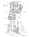
station 120 inside the blastingcabinet 15 will now be described. As illustrated inFIG. 4 , theworkpiece 20 to be processed, i.e., blasted with media, is mounted on apart holder 125. Preferably, thepart holder 125 has been hardened. Theworkpiece 20 is held in a predetermined position by a powered part hold-down apparatus 130. The powered part-hold-down apparatus 130 provides variable, compensating, cushioned clamping for maintaining theworkpiece 20 in the predetermined position during media blasting. The device is very important to facilitate processing high volume quantities of parts. This is especially important for parts such as gears which tend to rotate when peened since the hold-down device prevents free spinning of the parts. The hold-down device also controllably rotates the parts at a desired rate of rotation. Rotation of the powered part-hold-down apparatus 130 is provided via arotatable shaft 135. -
Hardened rods 140, preferably steel, provide a support system for a gun-rack assembly 145. The gun-rack assembly 145 holds anozzle holder 150. Ablast nozzle 155, to which the blastinghoses 115 are connected is attached tonozzle holder 150. Theblast nozzle 155 directs a stream of media, suspended in air, against the surface of theworkpiece 20. Preferably, the blast nozzle is positioned between approximately 10,16 to 20,32 cm (four to eight inches) away from theworkpiece 20. Although, only oneblast nozzle 155 is illustrated inFIG. 4 , it will be understood to those skilled in the art that a plurality ofblast nozzles 155 could be used. In a preferred embodiment of the present invention, foursuch blast nozzles 155 are located in the blastingcabinet 15, as shown inFIG. 3 . The blastingcabinet 15, containing the part-hold-down apparatus 130 and blasting apparatus is also provided with adoor 160 for installation of anew workpiece 20. - Operation of the present media blasting device will now be described. After a
gear 20 is placed in the part-hold-down apparatus 130,door 160 is closed. A stream of media suspended in air is then directed against thegear 20 by theblast nozzle 155. As the media are blasted, the gear is controllably rotated by the powered part-hold-down apparatus 130. This controlled rotation ensures even peening of the surface of thegear 20 and obviates use of a high directivity stream of media, hence making the use of water-supported media unnecessary. - The powered part-hold-down apparatus is preferably rotated at between 8-12 rpm. A rate of rotation of 10-12 rpm, however, has been found to be particularly effective for treatment of gears. The rate of rotation can be related to the degree of peening required and to the evenness of dimpling on the resulting surface. A slow controlled rotation permits even peening with uniform small dimpling and prevents the media stream from striking the surface unevenly, resulting in indentations that could act as crack precursors. The controlled rotation ensures that media, e.g. cut wire, ceramic beads, fine steel beads, or glass beads, are directed towards the root and tooth face of the gear during the course of the rotation. By ensuring even peening, the operational characteristics of the
gear 20 are improved. - In a one embodiment a smaller mass flowrate of media is blasted at higher velocity and for a longer time than in the prior art methods. The preferred flowrate depends on the type and size of media used, as well as the particular application involved. For treatment of gears, we have found a media flowrate of approximately 0,68-1,36 kg/minute (1.5-3 lb/minute) to be effective. Of course, other flowrates could be used, depending on the results desired. This flowrate was found to be effective with glass media, ceramic media, and fine steel media of mesh size falling in the range of 50-100 mesh. In a preferred embodiment of the present invention, however, 60-100 mesh glass media are used. When 60-100 mesh glass media were used to treat certain gears, including those made using 8620 steel, a marked improvement in the operational characteristics of such gears was observed. The choice of media to be used depends upon the application and the relative economics. Ceramic and steel media last longer than glass; however, these media are more expensive.
- After the media collide with the
gear 20 they fall into thecabinet media hopper 25 and are then conveyed to the reclaimsystem 35. The reusable media are separated from the fines and dust and are returned to the blastingstation 120 after mixing with virgin media. Such mixing reduces media wastage. The reuse of partially broken media also improves the polishing effect of the media upon thegear 20. - It has been found that satisfactory results may be achieved using glass media for blast treatment of certain gears, including those made of certain metals such as 8620 steel, gears made with other materials such as 5130 m steel have proved to be less than desirable using glass media. In general, the blast treatment with ceramic media of the invention has been found to be effective with a broad assortment of gear types made from a variety of metals. A number of oxide ceramics may be used in the process, such as for example, ZrO.sub.2, AL.sub.2 O.sub.3, SiO.sub.2, MgO, etc. Preferred media includes a crystalline zirconia uniformly enclosed in a silica glassy phase. Such media are sold under the tradename ZIRBLAST™ and ZIRSHOT™ by SEPR Co. of Paris le Defense, France.
- Surprisingly, the blast treatment using ceramic media has been found to produce significantly better results then for blast treatment using glass treatment for certain metallic gears, e.g., in providing improved resistance to pitting of gear teeth surfaces as well as improved strength in the gear tooth root radius relative to prior methods. For such gear applications, it has been found that the ceramic media from between 40 to 100 virgin mesh, a flow rate of between 0,45 to 11,34 kg/minute (1 to 25 pounds per minute), cycle time between 15 seconds and 180 seconds, pressure of between 241,32 and 620,53 kPa (35 and 90 psi), a rotation rate of the gear of between about 5-25 rpm, and an Almen intensity of between 15 n and 28 n are effective in treating gears. Superior results have been observed in such gears under preferred processing conditions which included a small mass flow rate of between 0,45 and 1,36 kg (1 to 3 pounds per minute), a pressures of between 482,63 and 551,58 kPa (70 and 80 psi), cycle time of between 15 seconds and 120 seconds, a rotation rate of the gear of about 8-12 rpm, media diameter of between about 0.210 mm and 0.150 mm mesh. Preferably, since ceramic media is relatively expensive, it is collected after blasting the gear and recycled by adding it to virgin media such that, after initial start up of the system, a recycled media mixture including virgin media and recycled media is used. In this preferred process, a 170-200 mesh screen is used as a bottom screen in the separation means of the media reclaim system to exclude small media fragments from the recycled media mixture.
- In a still further embodiment of the invention, a method of treating a metallic gear with a fine metallic media blast stream is illustrated utilizing the apparatus described above. The preferred method includes a media flow rate between about 0,45 and 1,81 kg/minute (1 and 4 lb/minute), a diameter of the media between about 150 micron and 200 micron, a pressure between 482,63 and 551,58 kPa (70 and 80 psi), an Almen range between about 18N and 26N. Preferably, the fine steel media is collected after blasting the gear and is recycled.
- As steel shot media lasts significantly longer than ceramic or glass media, very little virgin media is required to be added to the apparatus. This results in significant reduction in the monitoring, and maintenance requirements as well as in the amount of media used for successful mass processing of gears. Metallic gears treated in this manner typically have fewer and less well defined dimples on their surface structure then for the media blasting processes disclosed herein using glass or ceramic media. Moreover, the gears so treated exhibit lesser fatigue strength then glass media and ceramic media treatments disclosed herein. However, in dynamometer testing, the fine steel media exceeded 70 hours of continuous use prior to failure which significantly exceeds the 40 hour to failure result expected on coated gears. Due to the reduced maintenance, monitoring, and media costs, the fine steel media process disclosed herein is a lower cost method which provides superior results to conventional shot peening of gears. Fine steel media peening is sufficient for many gears which exhibit good surface pitting resistance. When much higher degree of pitting is exhibited during dynamometer testing of gears, media blast treatment with ceramic media is preferred.
- Using the ceramic blast treatment apparatus described herein, gears have been produced in a double peening step process as follows. A gear is media blasted by directing a first media (e.g., cut wire) against exposed surfaces on the gear. The step of media blasting (peening) with the first media makes the gear teeth root stronger. After media blasting with the first media, the gear is blasted by directing a second media (glass, ceramic or fine steel beads) against exposed surfaces on the gear. The step of media blasting (peening) with the second media makes the gear surface stronger and leaves the surface somewhat roughened. The roughened surface has dimples or indentations resulting from blasting with, for example, media between about 150 µm and 200 µm. Such blasting results in a dimple or indentation smaller than 150 µm and typically less than 75 µm. These small indentations provide high compressive stress and facilitate oil retention on the gear surface during use of the gear. Subsequent finishing reduces the size of the dimples or indentations but the high compressive stress and oil retention advantages remain on the gear surface.
- After double peening the
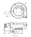
gear 201 is transferred to abowl 200 containing a fine finishing medium 212.Bowl 200 is depicted inFig. 5 (gears 201 are present in the fine finishing medium 212 but gears 201 are not shown inFig. 5 ).Bowl 200 has anoutlet 202, aninlet 204,sides 206, top 208 and a bottom 210. A wet acidic fine finishing medium 212 is provided in sufficient amount to wet thegears 201 andceramic media 212.Fig. 6 is a photo of a portion of abowl 200 withceramic media 212 and gears 201 prior to closing thebowl 200 for the vibration step. The relative size of thegear 201 andceramic media 212 shown are but one example of agear 201 andceramic media 212. Typically the ceramic media is smaller than that shown inFig. 6 . That is, the relative size of theceramic media 212 and gears 201 is such that themedia 212 is small enough to fit into the space between the gear teeth so that during fine finishing (vibration) the gear surfaces between the teeth are fine finished. Vibration of thebowl 200 is coupled to thebowl 200 viavibration coupler 214. The fine finishing medium 212 comprises a mixture of ceramic media with a slightly acidic solution.Fig. 7 shows a portion of the production facility with three coveredbowls 200.Figs. 8-10 are drawings of the bowls in a production facility. Each bowl is supported on the floor by three springs (more or fewer springs may be used). As seen inFig. 7 the threebowls 200 are covered for sound reduction, etc. Thebowl 200 is typically made of steel and has a polyurethane liner which couples the vibrations to the medium. As seen in, for example,Fig. 6 , the inside of thebowl 200 has achannel 250 extending around the entire inner periphery of thebowl 200. The center portion of the bowl is in the form of a cylinder (see outside wall of the cylinder at 300 inFig. 6 ) with the outsideperipheral wall 400 being spaced from thecylinder wall 300 by achannel 250. An opening with a removable cover is provided in the side of thebowl 200 to allow the contents to be removed. The inside of thechannel 250 has a banked shape so that when vibrations are coupled to the bowl the contents move along the channel in a circular flow. Other channel shapes may be imparted to the channel wall or floor to move the contents in a circular fashion. This movement enhances mixing of the contents whereby all surfaces of thegears 201 are exposed and subject to the smoothing action of themedia 212 in thechannel 250 with thegears 201. - The gear is wetted with the fine finishing medium in the bowl and vibrations are coupled to the bowl to vibrate the superfinishing medium with the wetted gear therein. The vibration is continued for a time sufficient to achieve a gear which has a finish of 5-25 Ra. During vibration (fine finishing) additional water and/or fine finishing medium may be added via one or
more inlets 204. Excess fine finishing medium, water etc, may be removed viaoutlet 202. Fine finishing is continued to smooth the gear (workpiece) surfaces but to leave sufficient dimples, indentations, etc. to enhance oil retention at the surface of the gear. A finish of zero Ra is not desired as this leaves a completely smooth finish with no surface dimples, indentations, etc. for enhancing oil retention. It is thought that the dimples provide locations for the oil to collect and be retained during gear operation whereby an amount of lubrication combines with gear smoothness to add to the working life of the gear. It has been found that fine finishing to a desired range of 5-25 Ra after the double peening discussed above adds significantly longer life to gears. After fine finishing the gear is removed from the bowl, washed and rinsed. The gear is treated with rust inhibitor in a final step whereby a gear with enhanced wear properties is provided. - In an embodiment not according to the invention the gears are fine finished in a bowl without the addition of liquid medium (i.e., with dry fine finishing medium). The gears are in effect fine finished while dry and in the presence of wear material that smoothes the gear surface, but wherein the wear material is not in liquid form. Coupling vibrations to the container to vibrate the fine finishing medium with the gear reduces the size of the indentations on the surfaces of the gear leaving compressive stress and oil retention advantages remaining on the gear surface. The surface resulting after finishing has smoothness as discussed above with indentations resulting from peening and reduced by but remaining after finishing.
- The media peening steps result in a gear with a residual compressive stress in the gear root radius of between at least 551,58 MPa (80 KSI) and in the gear surface of at least 551,58 MPa (80 KSI). At
depths µm 200 KSI at 0.001 inch and 1,55 kPa at 0,51 mm (225 KSI at 0.020 inch). - For gears treated by the above-discussed preferred two step media blasting method followed by fine finishing tests confirm that gears so treated exhibit superior performance relative to gears not treated with this three step process. It has been found that gears treated with this preferred process exhibit superior fatigue strength having performed adequately with little evidence of wear for hundreds of hours in tests. In contrast, gears treated by conventional methods can be expected to fail in as little as 20 hours in dynamometer testing.
- While the method of media blast treatment for gears is disclosed herein with respect to a hold down apparatus, it is contemplated that other conventional part holders and blasting apparatus may also be used with the steps described herein. The above discussed process recognizes that most often gears need steel peening at the gear root to prevent fatigue bending in the root radius.
Claims (7)
- A method of processing a metallic gear 20, 201 comprising
providing a gear 20, 201,
directing a first peening media at the metallic gear 20, 201 thereby exposing a plurality of surfaces on the metallic gear 20, 201 to the first peening media whereby the strength and wear properties of the teeth roots of the gear are enhanced,
washing the gear 20, 201, and
rinsing the gear 20, 201 with rust inhibitor
characterized by, prior to washing and rinsing:directing a second peening media at the metallic gear 20, 201 thereby exposing a plurality of surfaces on the metallic gear 20, 201 to the second peening media whereby the surface compressive stress of the surface of the gear 20, 201 is enhanced,providing a vibratory fine finishing container (200),placing a fine finishing medium (212) comprising ceramic media in a slightly acidic solution in the vibratory fine finishing container,placing the gear 20, 201 with the fine finishing medium in the vibratory fine finishing container (200),coupling vibrations to the vibratory fine finishing container to vibrate the fine finishing medium (212) with the gear 20, 201, andremoving the gear 20, 201 from the vibratory fine finishing container (200) upon achieving a fine finish of the gear 20, 201 from 5-25 Ra. - A method according to claim 1 wherein the container is a polyurethane lined steel bowl (200).
- A method of claim 1 wherein the first peening media comprise cut wire.
- The method of claim 1 wherein the second peening media comprise one of glass beads, ceramic beads and fine steel beads.
- The method of claim 4 wherein the peening media have a diameter of less than 250 µm.
- A method according to claim 1 wherein the first peening media comprise ceramic media which is directed at the metallic gear 20, 201 at a pressure of between 172.37 kPa (25 psi) and 620.53 kPa (90 psi) and wherein the ceramic media has a diameter of between 0.210 mm and 0.150 mm when added as virgin media.
- The method according to any one of the previous claims, wherein the second peening media have a size of 150 to 200 µm.
Priority Applications (4)
| Application Number | Priority Date | Filing Date | Title |
|---|---|---|---|
| ES10169858.7T ES2541004T3 (en) | 2010-07-16 | 2010-07-16 | Procedure for blasting and vibrating gear finishing |
| EP10169858.7A EP2436487B1 (en) | 2010-07-16 | 2010-07-16 | Method for the peening and vibratory finishing of gears |
| HUE10169858A HUE025386T2 (en) | 2010-07-16 | 2010-07-16 | Method for the peening and vibratory finishing of gears |
| PL10169858T PL2436487T3 (en) | 2010-07-16 | 2010-07-16 | Method for the peening and vibratory finishing of gears |
Applications Claiming Priority (1)
| Application Number | Priority Date | Filing Date | Title |
|---|---|---|---|
| EP10169858.7A EP2436487B1 (en) | 2010-07-16 | 2010-07-16 | Method for the peening and vibratory finishing of gears |
Publications (2)
| Publication Number | Publication Date |
|---|---|
| EP2436487A1 EP2436487A1 (en) | 2012-04-04 |
| EP2436487B1 true EP2436487B1 (en) | 2015-06-03 |
Family
ID=45445689
Family Applications (1)
| Application Number | Title | Priority Date | Filing Date |
|---|---|---|---|
| EP10169858.7A Not-in-force EP2436487B1 (en) | 2010-07-16 | 2010-07-16 | Method for the peening and vibratory finishing of gears |
Country Status (4)
| Country | Link |
|---|---|
| EP (1) | EP2436487B1 (en) |
| ES (1) | ES2541004T3 (en) |
| HU (1) | HUE025386T2 (en) |
| PL (1) | PL2436487T3 (en) |
Families Citing this family (1)
| Publication number | Priority date | Publication date | Assignee | Title |
|---|---|---|---|---|
| FR3093661A1 (en) | 2019-03-14 | 2020-09-18 | Psa Automobiles Sa | MANUFACTURING PROCESS OF A GEAR PART, ESPECIALLY FOR A MOTOR VEHICLE GEARBOX |
Citations (2)
| Publication number | Priority date | Publication date | Assignee | Title |
|---|---|---|---|---|
| US4307544A (en) * | 1979-11-28 | 1981-12-29 | Roto-Finish Company, Inc. | Finishing machine with abrasive lined chamber and method of finishing |
| EP2110203A1 (en) * | 2003-05-30 | 2009-10-21 | REM Technologies, Inc. | Planetary gearbox |
Family Cites Families (7)
| Publication number | Priority date | Publication date | Assignee | Title |
|---|---|---|---|---|
| US3073022A (en) * | 1959-04-03 | 1963-01-15 | Gen Motors Corp | Shot-peening treatments |
| US5272897A (en) | 1992-05-12 | 1993-12-28 | Engineered Abrasives, Inc. | Part hold down apparatus for part processing machine |
| JP3730015B2 (en) * | 1998-06-02 | 2005-12-21 | 株式会社不二機販 | Surface treatment method for metal products |
| US6612909B2 (en) * | 1998-09-11 | 2003-09-02 | Engineered Abrasives, Inc. | Media blasting apparatus and method to prevent gear pitting |
| JP2000126929A (en) * | 1998-10-23 | 2000-05-09 | Univ Saga | Treatment system for enhancing gear quality and barrel treatment device used therein |
| US20020072306A1 (en) * | 2000-06-14 | 2002-06-13 | Carpenter Steven J. | Chamber-type vibratory finisher with blasting nozzle |
| JP4502594B2 (en) * | 2003-05-22 | 2010-07-14 | 富士重工業株式会社 | Gear manufacturing method |
-
2010
- 2010-07-16 PL PL10169858T patent/PL2436487T3/en unknown
- 2010-07-16 EP EP10169858.7A patent/EP2436487B1/en not_active Not-in-force
- 2010-07-16 HU HUE10169858A patent/HUE025386T2/en unknown
- 2010-07-16 ES ES10169858.7T patent/ES2541004T3/en active Active
Patent Citations (2)
| Publication number | Priority date | Publication date | Assignee | Title |
|---|---|---|---|---|
| US4307544A (en) * | 1979-11-28 | 1981-12-29 | Roto-Finish Company, Inc. | Finishing machine with abrasive lined chamber and method of finishing |
| EP2110203A1 (en) * | 2003-05-30 | 2009-10-21 | REM Technologies, Inc. | Planetary gearbox |
Also Published As
| Publication number | Publication date |
|---|---|
| ES2541004T3 (en) | 2015-07-15 |
| HUE025386T2 (en) | 2016-02-29 |
| EP2436487A1 (en) | 2012-04-04 |
| PL2436487T3 (en) | 2015-11-30 |
Similar Documents
| Publication | Publication Date | Title |
|---|---|---|
| CA2709474C (en) | Peen finishing | |
| US11607757B2 (en) | Machining system, apparatus and method | |
| US20200406423A1 (en) | Part processing and cleaning apparatus and method of same | |
| CA2448485C (en) | Ceramic blasting apparatus and method to prevent gear pitting | |
| US6238268B1 (en) | Media blasting apparatus and method | |
| EP2436487B1 (en) | Method for the peening and vibratory finishing of gears | |
| JP2012081569A (en) | Peening finishing | |
| WO2012074036A1 (en) | Hollow spring and method for manufacturing same | |
| JPS63207563A (en) | Grinding/polishing/cleaning method for die by electric discharge machine | |
| CN110712115A (en) | Grinding device and grinding method | |
| KR20010112847A (en) | Blasting material for blasting process | |
| KR20190018374A (en) | Blast nozzle device | |
| WO2019245491A2 (en) | Disk hand held sand blasting machine | |
| JP2024125638A (en) | Steel bridge conservation method | |
| CN114918815B (en) | Method for accelerating superfinishing of blade shot blasting surface medium | |
| EP4245459A1 (en) | Component treatment method and apparatus | |
| CN212330725U (en) | Shot blasting rust removal assembly line | |
| CN108486339A (en) | A kind of ball blast technique of bent axle | |
| CN112008610A (en) | Shot blasting rust removal assembly line | |
| Plaster | Mechanical Surface Treatments | |
| Shultz et al. | Metallic Abrasives for Surface Preparation | |
| KR20120008168A (en) | Cylinder shaped abradant for pretreatment | |
| JPH0760647A (en) | Blast work method for metallic product and shot for blast work | |
| KR20090084169A (en) | Blast nozzle device |
Legal Events
| Date | Code | Title | Description |
|---|---|---|---|
| PUAI | Public reference made under article 153(3) epc to a published international application that has entered the european phase |
Free format text: ORIGINAL CODE: 0009012 |
|
| AK | Designated contracting states |
Kind code of ref document: A1 Designated state(s): AL AT BE BG CH CY CZ DE DK EE ES FI FR GB GR HR HU IE IS IT LI LT LU LV MC MK MT NL NO PL PT RO SE SI SK SM TR |
|
| AX | Request for extension of the european patent |
Extension state: BA ME RS |
|
| 17P | Request for examination filed |
Effective date: 20130121 |
|
| 17Q | First examination report despatched |
Effective date: 20130510 |
|
| GRAP | Despatch of communication of intention to grant a patent |
Free format text: ORIGINAL CODE: EPIDOSNIGR1 |
|
| INTG | Intention to grant announced |
Effective date: 20141222 |
|
| GRAS | Grant fee paid |
Free format text: ORIGINAL CODE: EPIDOSNIGR3 |
|
| GRAA | (expected) grant |
Free format text: ORIGINAL CODE: 0009210 |
|
| AK | Designated contracting states |
Kind code of ref document: B1 Designated state(s): AL AT BE BG CH CY CZ DE DK EE ES FI FR GB GR HR HU IE IS IT LI LT LU LV MC MK MT NL NO PL PT RO SE SI SK SM TR |
|
| REG | Reference to a national code |
Ref country code: GB Ref legal event code: FG4D |
|
| REG | Reference to a national code |
Ref country code: CH Ref legal event code: EP |
|
| REG | Reference to a national code |
Ref country code: AT Ref legal event code: REF Ref document number: 729668 Country of ref document: AT Kind code of ref document: T Effective date: 20150715 Ref country code: ES Ref legal event code: FG2A Ref document number: 2541004 Country of ref document: ES Kind code of ref document: T3 Effective date: 20150715 Ref country code: IE Ref legal event code: FG4D |
|
| REG | Reference to a national code |
Ref country code: DE Ref legal event code: R096 Ref document number: 602010025012 Country of ref document: DE Ref country code: DE Ref legal event code: R096 Ref document number: 602010025012 Country of ref document: DE Effective date: 20150716 |
|
| REG | Reference to a national code |
Ref country code: FR Ref legal event code: PLFP Year of fee payment: 6 |
|
| REG | Reference to a national code |
Ref country code: AT Ref legal event code: MK05 Ref document number: 729668 Country of ref document: AT Kind code of ref document: T Effective date: 20150603 |
|
| PG25 | Lapsed in a contracting state [announced via postgrant information from national office to epo] |
Ref country code: NO Free format text: LAPSE BECAUSE OF FAILURE TO SUBMIT A TRANSLATION OF THE DESCRIPTION OR TO PAY THE FEE WITHIN THE PRESCRIBED TIME-LIMIT Effective date: 20150903 Ref country code: HR Free format text: LAPSE BECAUSE OF FAILURE TO SUBMIT A TRANSLATION OF THE DESCRIPTION OR TO PAY THE FEE WITHIN THE PRESCRIBED TIME-LIMIT Effective date: 20150603 Ref country code: LT Free format text: LAPSE BECAUSE OF FAILURE TO SUBMIT A TRANSLATION OF THE DESCRIPTION OR TO PAY THE FEE WITHIN THE PRESCRIBED TIME-LIMIT Effective date: 20150603 Ref country code: FI Free format text: LAPSE BECAUSE OF FAILURE TO SUBMIT A TRANSLATION OF THE DESCRIPTION OR TO PAY THE FEE WITHIN THE PRESCRIBED TIME-LIMIT Effective date: 20150603 |
|
| PGFP | Annual fee paid to national office [announced via postgrant information from national office to epo] |
Ref country code: DE Payment date: 20150729 Year of fee payment: 6 Ref country code: GB Payment date: 20150727 Year of fee payment: 6 Ref country code: ES Payment date: 20150727 Year of fee payment: 6 |
|
| REG | Reference to a national code |
Ref country code: NL Ref legal event code: MP Effective date: 20150603 |
|
| REG | Reference to a national code |
Ref country code: LT Ref legal event code: MG4D |
|
| PG25 | Lapsed in a contracting state [announced via postgrant information from national office to epo] |
Ref country code: BG Free format text: LAPSE BECAUSE OF FAILURE TO SUBMIT A TRANSLATION OF THE DESCRIPTION OR TO PAY THE FEE WITHIN THE PRESCRIBED TIME-LIMIT Effective date: 20150903 Ref country code: LV Free format text: LAPSE BECAUSE OF FAILURE TO SUBMIT A TRANSLATION OF THE DESCRIPTION OR TO PAY THE FEE WITHIN THE PRESCRIBED TIME-LIMIT Effective date: 20150603 Ref country code: AT Free format text: LAPSE BECAUSE OF FAILURE TO SUBMIT A TRANSLATION OF THE DESCRIPTION OR TO PAY THE FEE WITHIN THE PRESCRIBED TIME-LIMIT Effective date: 20150603 Ref country code: GR Free format text: LAPSE BECAUSE OF FAILURE TO SUBMIT A TRANSLATION OF THE DESCRIPTION OR TO PAY THE FEE WITHIN THE PRESCRIBED TIME-LIMIT Effective date: 20150904 |
|
| PGFP | Annual fee paid to national office [announced via postgrant information from national office to epo] |
Ref country code: PL Payment date: 20150720 Year of fee payment: 6 Ref country code: FR Payment date: 20150717 Year of fee payment: 6 |
|
| REG | Reference to a national code |
Ref country code: PL Ref legal event code: T3 |
|
| PGFP | Annual fee paid to national office [announced via postgrant information from national office to epo] |
Ref country code: IT Payment date: 20150825 Year of fee payment: 6 |
|
| PG25 | Lapsed in a contracting state [announced via postgrant information from national office to epo] |
Ref country code: EE Free format text: LAPSE BECAUSE OF FAILURE TO SUBMIT A TRANSLATION OF THE DESCRIPTION OR TO PAY THE FEE WITHIN THE PRESCRIBED TIME-LIMIT Effective date: 20150603 |
|
| PG25 | Lapsed in a contracting state [announced via postgrant information from national office to epo] |
Ref country code: RO Free format text: LAPSE BECAUSE OF NON-PAYMENT OF DUE FEES Effective date: 20150603 Ref country code: SK Free format text: LAPSE BECAUSE OF FAILURE TO SUBMIT A TRANSLATION OF THE DESCRIPTION OR TO PAY THE FEE WITHIN THE PRESCRIBED TIME-LIMIT Effective date: 20150603 Ref country code: IS Free format text: LAPSE BECAUSE OF FAILURE TO SUBMIT A TRANSLATION OF THE DESCRIPTION OR TO PAY THE FEE WITHIN THE PRESCRIBED TIME-LIMIT Effective date: 20151003 Ref country code: CZ Free format text: LAPSE BECAUSE OF FAILURE TO SUBMIT A TRANSLATION OF THE DESCRIPTION OR TO PAY THE FEE WITHIN THE PRESCRIBED TIME-LIMIT Effective date: 20150603 Ref country code: PT Free format text: LAPSE BECAUSE OF FAILURE TO SUBMIT A TRANSLATION OF THE DESCRIPTION OR TO PAY THE FEE WITHIN THE PRESCRIBED TIME-LIMIT Effective date: 20151006 |
|
| PGFP | Annual fee paid to national office [announced via postgrant information from national office to epo] |
Ref country code: HU Payment date: 20150728 Year of fee payment: 6 |
|
| REG | Reference to a national code |
Ref country code: CH Ref legal event code: PL Ref country code: HU Ref legal event code: AG4A Ref document number: E025386 Country of ref document: HU |
|
| REG | Reference to a national code |
Ref country code: DE Ref legal event code: R097 Ref document number: 602010025012 Country of ref document: DE |
|
| PG25 | Lapsed in a contracting state [announced via postgrant information from national office to epo] |
Ref country code: MC Free format text: LAPSE BECAUSE OF FAILURE TO SUBMIT A TRANSLATION OF THE DESCRIPTION OR TO PAY THE FEE WITHIN THE PRESCRIBED TIME-LIMIT Effective date: 20150603 |
|
| PLBE | No opposition filed within time limit |
Free format text: ORIGINAL CODE: 0009261 |
|
| STAA | Information on the status of an ep patent application or granted ep patent |
Free format text: STATUS: NO OPPOSITION FILED WITHIN TIME LIMIT |
|
| REG | Reference to a national code |
Ref country code: IE Ref legal event code: MM4A |
|
| PG25 | Lapsed in a contracting state [announced via postgrant information from national office to epo] |
Ref country code: LI Free format text: LAPSE BECAUSE OF NON-PAYMENT OF DUE FEES Effective date: 20150731 Ref country code: CH Free format text: LAPSE BECAUSE OF NON-PAYMENT OF DUE FEES Effective date: 20150731 Ref country code: DK Free format text: LAPSE BECAUSE OF FAILURE TO SUBMIT A TRANSLATION OF THE DESCRIPTION OR TO PAY THE FEE WITHIN THE PRESCRIBED TIME-LIMIT Effective date: 20150603 |
|
| 26N | No opposition filed |
Effective date: 20160304 |
|
| PG25 | Lapsed in a contracting state [announced via postgrant information from national office to epo] |
Ref country code: SI Free format text: LAPSE BECAUSE OF FAILURE TO SUBMIT A TRANSLATION OF THE DESCRIPTION OR TO PAY THE FEE WITHIN THE PRESCRIBED TIME-LIMIT Effective date: 20150603 |
|
| PG25 | Lapsed in a contracting state [announced via postgrant information from national office to epo] |
Ref country code: IE Free format text: LAPSE BECAUSE OF NON-PAYMENT OF DUE FEES Effective date: 20150716 |
|
| PG25 | Lapsed in a contracting state [announced via postgrant information from national office to epo] |
Ref country code: BE Free format text: LAPSE BECAUSE OF FAILURE TO SUBMIT A TRANSLATION OF THE DESCRIPTION OR TO PAY THE FEE WITHIN THE PRESCRIBED TIME-LIMIT Effective date: 20150603 |
|
| REG | Reference to a national code |
Ref country code: DE Ref legal event code: R119 Ref document number: 602010025012 Country of ref document: DE |
|
| GBPC | Gb: european patent ceased through non-payment of renewal fee |
Effective date: 20160716 |
|
| PG25 | Lapsed in a contracting state [announced via postgrant information from national office to epo] |
Ref country code: MT Free format text: LAPSE BECAUSE OF FAILURE TO SUBMIT A TRANSLATION OF THE DESCRIPTION OR TO PAY THE FEE WITHIN THE PRESCRIBED TIME-LIMIT Effective date: 20150603 |
|
| PG25 | Lapsed in a contracting state [announced via postgrant information from national office to epo] |
Ref country code: FR Free format text: LAPSE BECAUSE OF NON-PAYMENT OF DUE FEES Effective date: 20160801 Ref country code: DE Free format text: LAPSE BECAUSE OF NON-PAYMENT OF DUE FEES Effective date: 20170201 Ref country code: HU Free format text: LAPSE BECAUSE OF NON-PAYMENT OF DUE FEES Effective date: 20160717 |
|
| REG | Reference to a national code |
Ref country code: FR Ref legal event code: ST Effective date: 20170331 |
|
| PG25 | Lapsed in a contracting state [announced via postgrant information from national office to epo] |
Ref country code: GB Free format text: LAPSE BECAUSE OF NON-PAYMENT OF DUE FEES Effective date: 20160716 Ref country code: SM Free format text: LAPSE BECAUSE OF FAILURE TO SUBMIT A TRANSLATION OF THE DESCRIPTION OR TO PAY THE FEE WITHIN THE PRESCRIBED TIME-LIMIT Effective date: 20150603 |
|
| PG25 | Lapsed in a contracting state [announced via postgrant information from national office to epo] |
Ref country code: SE Free format text: LAPSE BECAUSE OF FAILURE TO SUBMIT A TRANSLATION OF THE DESCRIPTION OR TO PAY THE FEE WITHIN THE PRESCRIBED TIME-LIMIT Effective date: 20150603 Ref country code: CY Free format text: LAPSE BECAUSE OF FAILURE TO SUBMIT A TRANSLATION OF THE DESCRIPTION OR TO PAY THE FEE WITHIN THE PRESCRIBED TIME-LIMIT Effective date: 20150603 Ref country code: NL Free format text: LAPSE BECAUSE OF FAILURE TO SUBMIT A TRANSLATION OF THE DESCRIPTION OR TO PAY THE FEE WITHIN THE PRESCRIBED TIME-LIMIT Effective date: 20150603 |
|
| PG25 | Lapsed in a contracting state [announced via postgrant information from national office to epo] |
Ref country code: IT Free format text: LAPSE BECAUSE OF NON-PAYMENT OF DUE FEES Effective date: 20160716 |
|
| PG25 | Lapsed in a contracting state [announced via postgrant information from national office to epo] |
Ref country code: LU Free format text: LAPSE BECAUSE OF NON-PAYMENT OF DUE FEES Effective date: 20150716 |
|
| PG25 | Lapsed in a contracting state [announced via postgrant information from national office to epo] |
Ref country code: PL Free format text: LAPSE BECAUSE OF NON-PAYMENT OF DUE FEES Effective date: 20160716 |
|
| PG25 | Lapsed in a contracting state [announced via postgrant information from national office to epo] |
Ref country code: ES Free format text: LAPSE BECAUSE OF NON-PAYMENT OF DUE FEES Effective date: 20160717 |
|
| PG25 | Lapsed in a contracting state [announced via postgrant information from national office to epo] |
Ref country code: MK Free format text: LAPSE BECAUSE OF FAILURE TO SUBMIT A TRANSLATION OF THE DESCRIPTION OR TO PAY THE FEE WITHIN THE PRESCRIBED TIME-LIMIT Effective date: 20150603 |
|
| PG25 | Lapsed in a contracting state [announced via postgrant information from national office to epo] |
Ref country code: AL Free format text: LAPSE BECAUSE OF FAILURE TO SUBMIT A TRANSLATION OF THE DESCRIPTION OR TO PAY THE FEE WITHIN THE PRESCRIBED TIME-LIMIT Effective date: 20150603 |
|
| REG | Reference to a national code |
Ref country code: ES Ref legal event code: FD2A Effective date: 20181116 |
|
| PG25 | Lapsed in a contracting state [announced via postgrant information from national office to epo] |
Ref country code: TR Free format text: LAPSE BECAUSE OF NON-PAYMENT OF DUE FEES Effective date: 20160716 |