EP2436312A1 - Computer tomography imaging device and method - Google Patents
Computer tomography imaging device and method Download PDFInfo
- Publication number
- EP2436312A1 EP2436312A1 EP09845074A EP09845074A EP2436312A1 EP 2436312 A1 EP2436312 A1 EP 2436312A1 EP 09845074 A EP09845074 A EP 09845074A EP 09845074 A EP09845074 A EP 09845074A EP 2436312 A1 EP2436312 A1 EP 2436312A1
- Authority
- EP
- European Patent Office
- Prior art keywords
- region
- interest
- ray
- image
- projection data
- Prior art date
- Legal status (The legal status is an assumption and is not a legal conclusion. Google has not performed a legal analysis and makes no representation as to the accuracy of the status listed.)
- Granted
Links
Images



Classifications
-
- A—HUMAN NECESSITIES
- A61—MEDICAL OR VETERINARY SCIENCE; HYGIENE
- A61B—DIAGNOSIS; SURGERY; IDENTIFICATION
- A61B6/00—Apparatus or devices for radiation diagnosis; Apparatus or devices for radiation diagnosis combined with radiation therapy equipment
- A61B6/02—Arrangements for diagnosis sequentially in different planes; Stereoscopic radiation diagnosis
- A61B6/03—Computed tomography [CT]
- A61B6/032—Transmission computed tomography [CT]
-
- A—HUMAN NECESSITIES
- A61—MEDICAL OR VETERINARY SCIENCE; HYGIENE
- A61B—DIAGNOSIS; SURGERY; IDENTIFICATION
- A61B6/00—Apparatus or devices for radiation diagnosis; Apparatus or devices for radiation diagnosis combined with radiation therapy equipment
- A61B6/06—Diaphragms
-
- A—HUMAN NECESSITIES
- A61—MEDICAL OR VETERINARY SCIENCE; HYGIENE
- A61B—DIAGNOSIS; SURGERY; IDENTIFICATION
- A61B6/00—Apparatus or devices for radiation diagnosis; Apparatus or devices for radiation diagnosis combined with radiation therapy equipment
- A61B6/44—Constructional features of apparatus for radiation diagnosis
- A61B6/4429—Constructional features of apparatus for radiation diagnosis related to the mounting of source units and detector units
- A61B6/4452—Constructional features of apparatus for radiation diagnosis related to the mounting of source units and detector units the source unit and the detector unit being able to move relative to each other
-
- A—HUMAN NECESSITIES
- A61—MEDICAL OR VETERINARY SCIENCE; HYGIENE
- A61B—DIAGNOSIS; SURGERY; IDENTIFICATION
- A61B6/00—Apparatus or devices for radiation diagnosis; Apparatus or devices for radiation diagnosis combined with radiation therapy equipment
- A61B6/46—Arrangements for interfacing with the operator or the patient
- A61B6/467—Arrangements for interfacing with the operator or the patient characterised by special input means
- A61B6/469—Arrangements for interfacing with the operator or the patient characterised by special input means for selecting a region of interest [ROI]
-
- G—PHYSICS
- G06—COMPUTING OR CALCULATING; COUNTING
- G06T—IMAGE DATA PROCESSING OR GENERATION, IN GENERAL
- G06T12/00—Tomographic reconstruction from projections
- G06T12/20—Inverse problem, i.e. transformations from projection space into object space
-
- G—PHYSICS
- G06—COMPUTING OR CALCULATING; COUNTING
- G06T—IMAGE DATA PROCESSING OR GENERATION, IN GENERAL
- G06T2211/00—Image generation
- G06T2211/40—Computed tomography
- G06T2211/416—Exact reconstruction
-
- G—PHYSICS
- G06—COMPUTING OR CALCULATING; COUNTING
- G06T—IMAGE DATA PROCESSING OR GENERATION, IN GENERAL
- G06T2211/00—Image generation
- G06T2211/40—Computed tomography
- G06T2211/421—Filtered back projection [FBP]
-
- G—PHYSICS
- G06—COMPUTING OR CALCULATING; COUNTING
- G06T—IMAGE DATA PROCESSING OR GENERATION, IN GENERAL
- G06T2211/00—Image generation
- G06T2211/40—Computed tomography
- G06T2211/424—Iterative
Definitions
- the present invention relates to a computer tomography (CT) imaging device, in particular to a device for CT imaging of a region of interest (ROI), and a CT imaging method for use in the such devices as well as a computer program product and a recording medium for implementing the imaging method.
- CT computer tomography
- CT technology has brought revolutionary impact on medical diagnosis and industrial nondestructive testing even since Hounsfield has invented the first CT machine in 1972, and CT has been one of the important detection measures in the industries of medical treatment, biology, aeronautics and astronautics, national defense, etc.
- X-ray cone-beam CT has been widely used in the fields of clinical medicine, security check, nondestructive detection, etc..
- spiral CT has been one of the indispensable measures for examination [1] .
- CT technology has currently achieved great success in the fields of industry, security check, medical care and so on, due to the complexity and the diversity of engineering application conditions, high requirements are put forth for further development of CT technology.
- CT technology faces with many difficulties in terms of large-sized imaging with high accuracy and medical imaging with low dose, etc.
- the CT scanning field of view is restricted by the width of the X-ray beam, the size of the detector and the angle of the view, which gives rise to the possibility that the projection data of the scanning of a large object has truncations in the two directions of the detector and the scanning angle;
- the current mainstream CT algorithms are all overall reconstruction methods with respect to an intact object, which require the X-ray beam to cover the slices of the object completely and can hardly deal with the occasion where the projection data is truncated.
- the detector of a CT device has been the key factor that influences the hardware cost of the CT device, and the price of the detector is directly proportional to the size and amount of the detector units.
- the price of detector remains high, which greatly limits the cost margin of CT products.
- the width of the X-ray beam for use in the current CT scanning must cover the width of the slices of the human body, however, the real interest region often only relates to a certain organ of the human body, and as a result, an unnecessary radiation dose on the human body during the CT scanning is greatly increased. If the present way of CT design is not changed, the radiation dose can hardly be reduced. At present, medical irradiation has been the largest artificial ionizing radiation source for the human being, and hence reducing the X-ray dose during CT examination has become a significant subject concerning the health of the entire public and the posterities of the society.
- the flat-panel detector based on amorphous selenium and amorphous silicon techniques now has a detector aperture of larger than 500mm X 500mm, and a pixel size of about 0.1mm, whereas the detector of multilayered spiral CT has only a unit size of about 0.5mm, so flat-panel detector can achieve CT images with much higher spatial resolutions compared with the spiral CT.
- the data transmission speed still cannot meet the requirements for cone-beam CT imaging, and there are no CT devices using flat-panel detectors for whole body imaging in the practice. If we are not directed at the entire human body, but at the organs of interest with small-scaled flat-panel detectors to achieve CT imaging of the region of interest with high accuracy, it is possible that the technical bottleneck of slow data transmission could be broken.
- the BPF algorithm of Zou and Pan is a reconstruction algorithm based on the PI line, wherein the PI line is a line segment connecting any two points in the scanning trace, and wherein the BPF algorithm requires the two end points of each PI line to fall outside the support of the object.
- the greatest advantage of the algorithm lies in that the image in the PI line can still be reconstructed exactly when the projection data is somewhat truncated, which makes it possible to perform CT reconstruction with respect to the ROI instead of the intact object.
- Defrise et al. obtained further achievements based on the BPF algorithm and eased the restriction of PI line by proving that when the PI line has only one end point outside the support of the object, the image in the PI line can still be reconstructed exactly with the projection data passing through the PI line [9] .
- Fig. 1 When the region of interest ROI falls within the support of the object, the ROI image cannot be reconstructed exactly with FOV only covering ROI, and additional projection information is needed for reconstructing the slice image of the ROI, and there are two groups of situations: (a) and (b) belong to one group of situations, i.e., an additional dark shadow region is added, and it is necessary that the projection data passing through the shadow region can be acquired, wherein the image of the dark shadow region is known; (c) and (d) belong to another group of situations, i.e., an additional shadow region B is added, and part or all of the region falls outside the support of the object.
- a group of situations i.e., an additional dark shadow region is added, and it is necessary that the projection data passing through the shadow region can be acquired, wherein the image of the dark shadow region is known
- (c) and (d) belong to another group of situations, i.e., an additional shadow region B is added, and part or all of the region falls outside the support of the object.
- the person to be detected only needs to be exposed to a dose of X-ray scanning the region of the suspicious tissue and a dose of X-ray passing through a very little aerial region outside of the body, which can reduce to a great extent the radiation dose on the person to be detected compared with the current whole body spiral CT scanning.
- the present invention is put forth based on the sufficiency condition of exact CT data reconstruction, in particular based on the situation (d).
- a method for CT imaging a region of interest of an object under examination comprising steps of: acquiring the CT projection data of the region of interest; acquiring the CT projection data of a region B, wherein at least part of the region B falls outside the support of the object under examination and the region B is selected to enable the selection of a group of PI line segments covering the region of interest, wherein each PI line passing through the region of interest passes through the region B; and reconstructing the CT projection data of the region of interest in accordance with the CT projection data of both the region of interest and the region B.
- a CT imaging device for CT imaging the region of interest of an object under examination, comprising: an X-ray generator for generating an X-ray beam for use in CT scanning; detectors for detecting the X-ray passing through the scanned region so as to generate projection data; carrier of the object under examination for carrying the object under examination moving in and out of the CT imaging device; a main controller for controlling the operation of the CT imaging device, such that the X-ray emitted from the X-ray generator only covers the region of interest so that the CT scanning is performed to obtain the projection data of the region of interest, and such that the X-ray emitted from the X-ray generator only covers the region B so that the CT scanning is performed to obtain the projection data of the region B, wherein at least part of the region B falls outside the support of the object under examination and the region B is selected to enable the selection of a group of PI line segments covering the region of interest, wherein each PI line passing through the region of interest passes through the region B
- the present invention further provides a computer program product comprising instructions for implementing the method steps of the CT imaging method of the present invention when loaded to a computer and operated thereon.
- the present invention further provides a recording medium, which stores instructions for implementing the method steps of the CT imaging method of the present invention when loaded to a computer and operated thereon.
- the 2D/3D slice image of a region of interest can be exactly reconstructed as long as the X-ray beam emitted from the X-ray source covers the region of interest, so it is possible to use a small-sized detector to perform CT imaging on the region of interest at any position of a large-sized object, which improves the speed of CT scanning and image reconstruction and cuts the hardware cost of a CT device, and meanwhile reduces to a great extent the radiation dose of the X-ray during the CT scanning. Therefore, the present invention is highly potential for market applications.
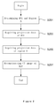
- FIG. 2 describes a computed tomography (CT) imaging method according to an embodiment of the present invention.
- a region of interest (ROI) of an object under examination to be the CT imaging is determined, and a region B having at least a part falling outside the support of the object is determined based on the determined ROI.
- the region B is selected to enable a selection of a group of PI line segments covering the ROI, wherein each PI line passing through the ROI passes through the region B (as shown in Figure 1 (d) ).
- the region B can be a spatial region of any size and shape.
- the region B can generally be selected as a circular or spherical spatial region with a diameter 10 times of that of the detector unit.
- other reference regions can be further determined.
- step S203 the ROI region is adjusted into the scanning field of view such that the X-ray beam for scanning only covers the ROI, and performs CT scanning for the ROI to acquire the CT projection data of the ROI.
- step S205 the region B is adjusted into the scanning field of view such that the X-ray beam only covers the region B and performs CT scanning for the region B to acquire the CT projection data of the region B.
- step S207 based on the CT projection data of the ROI acquired in step S203 and the CT projection data of the region B acquired in step S205, a CT image of the ROI is reconstructed according to the reconstruction method described in Figure 3 .
- the X-ray beam only covers the ROI or the region B, so the object under examination in the two times of scanning is exposed to a total X-ray radiation dose much less than that of a traditional CT scanning.
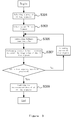
- FIG. 3 specifically describes the reconstruction method executed in step S207 as shown in Figure 2 .
- step S301 a group of PI line segments covering the ROI is selected, and it is ensured that each PI line passing through the ROI also passes through the region B.
- steps S303-S307 wherein for each PI line in the group of PI line segments selected in step S301, image reconstruction is performed along the PI line. Subsequently, in step S309, the reconstruction data of all of PI lines are combined to obtain the result ROI image.
- the procedure of PI-line-based image reconstruction is the same in 2D and 3D reconstruction. Take an example by a 2D image reconstruction to explain the image reconstruction processing executed in steps S303-S307 based on a PI line.
- a 2D image along a PI line is defined as function f ( r ) ⁇ L 2 (P), and thereby the image reconstruction processing is to seek for the intersection function fulfilling all the five constraints in formula (1).
- C 1 f ⁇ L 2 P
- Hf ⁇ x g x , x ⁇ a b ⁇ c d
- C 2 f ⁇ L 2 P
- f x f 0 x , x ⁇ a b
- C 3 f ⁇ L 2 P
- ⁇ - 1 + 1 ⁇ dxf x ⁇ ⁇ C f
- 4 f ⁇ L 2 P
- C 5 f ⁇ L 2 P
- f x ⁇ f max , x ⁇ - 1 , 1 where C f 1 ⁇ ⁇ ⁇ - 1 + 1 ⁇ dxf x can be obtained by directly calculating
- x ⁇ [-1,1] represents a normalized one dimensional PI line segment
- x ⁇ ( a,b ) is the part of the PI line segment within a region B falling outside the support of the object under examination
- ( c,d ) is the part of the PI line segment within the ROI, as shown in Figure 1 (d)
- f 0 ( x ) is an object image in the part of PI line segment within the region B, as it falls outside the support of the object under examination and is usually the air
- the image reconstruction value is generally set as 0.
- f max represents the possible maximum value in the reconstructed image, which can be set as an attenuation coefficient value of the material in the object having the maximum density according to the property of the object.
- the object under examination is usually human beings and the maximum value of the reconstructed image is generally that of the bone tissues, so f max can be set as an attenuation coefficient value of the bone tissues under corresponding X-ray energy.
- s r ⁇ 0 ⁇ u ⁇ ⁇
- condition C 1 can be implemented by POCS (Projection onto Convex Set) iterative calculation.
- the initial image f 0 ( x ) of the iteration can be an arbitrary estimate and set artificially, generally as all-zero.
- g ( x ) is calculated from the preceding formula (2), and during the POCS iterative procedure, it remains constant without back projection iterative computations.
- step S303 one PI line segment is selected from the group of PI line segments.
- step S305 a one dimensional Hilbert transform value of the selected PI line segment is calculated, which can be obtained in accordance with formula (2).
- step S307 limit inverse Hilbert transform is performed for the one dimensional Hilbert transform value calculated in step S305 to acquire the reconstruction image value of the PI line segment.
- a repeated iteration i.e., the POCS iterative procedure, between the reconstruction image domain and the Hilbert transform space domain is required to acquire a reconstruction image satisfying the accuracy requirement.
- the processing of step S307 can be performed in accordance with formulas (1) and (3)-(6).
- the above reconstruction method is not limited to a certain scanning manner, and it can be applicable to the CT scanning using parallel beam, sector beam or cone beam X-ray. Meanwhile, the reconstruction method is also applicable to different scanning traces, and the only difference lies in that the back projection formula (2) may change slightly in the weight coefficient due to the variation of the specific scanning manner, which only needs to make corresponding adjustments according to the specific scanning manner, so it will not be discussed any more.
- Figure 3 only provides a specific manner of reconstructing the CT image of the ROI in accordance with the CT projection data of the ROI and the region B.
- Other methods utilizing the CT projection data of the ROI and the region B in light of the principle of the present invention may also be applicable, and all these methods fall within the protection scope of the present invention.
- FIG. 4 shows a CT imaging device 400 according to an embodiment of the present invention, which performs CT imaging using the CT imaging method according to the present invention.
- the CT imaging device 400 comprises an X-ray generator 410 for generating an X-ray beam for use in scanning, a front collimator 420, detector arrangement 430, a detector position controller 440, a rotation mechanism 450, a carrier 460 of the object under examination, a main controller 470, a data processor 480 and display device 490.
- the X-ray emitted from the X-ray generator 410 is usually a sector beam (corresponding to a linear array detector) or a cone beam (corresponding to a planar array detector).
- the front collimator 420 is mounted at the position of an emergence window of the X-ray generator 410 for limiting the width of the X-ray beam, such that the width of the X-ray beam is consistent with the width of the detector in the detector arrangement.
- the front collimator 420 has the function of adjusting the width of the X-ray beam such that the X-ray beam only covers the ROI or the region B.
- Figure 5 shows the detailed structure of the front collimator 420.
- the front collimator 420 is composed of four X-ray shielding blocks 421a-421d, forming an X-ray emergence window 423 of a certain shape, which can be circular, rectangular or other shapes.
- a rectangle is illustrated as an example.
- the X-ray shielding blocks 421a-421d are made of substances capable of effectively absorbing X-ray energy (which can be high density materials such as lead, tungsten etc.), and are thick enough to block the penetration of X-ray.
- Each X-ray shielding blocks 421a-421d is provided with a set of servo motors 425 and precision lead screws 427 operating independently and located behind of the blocks (as shown in Figure 5(c) ).
- the servo motor 425 and the precision lead screw 427 are capable of, driving corresponding X-ray shielding blocks 421a-421d to move forward or backward along the precision lead screw 427 in accordance with given parameters under the control of the main controller 470.
- the X-ray emergence window 423 will be able to change the size and position of the window correspondingly with respect to different ROI or region B, so as to meet the requirement that the X-ray only covers the ROI or the region B during the scanning.
- the number of the X-ray shielding blocks is not necessarily four, and any X-ray shielding blocks capable of forming an X-ray emergence window of a certain shape can fall within the protection scope of the present invention.
- the detector arrangement 430 can adapt a linear array of detectors or a planar array of detectors, or a flat-panel detector with corresponding auxiliary devices.
- the detector arrangement 430 detects the X-ray passing through the scanned region to produce projection data and transmits the projection data to the data processor 480 for further processing by optical fiber cable, network cable, etc. wire or wirelessly.
- the detector position controller 440 is used to control the position of the detector arrangement 430, and include the servo motor 441 and the precision lead screw 443 and so on.
- Figure 6 explains the detailed structure of the detector position controller 440 in an embodiment where the detector arrangement 430 is a planar array detector. As shown in Figure 6 , the detector arrangement 430 is fixed to the precision lead screw 443 by means of a card slot, and the servo motor 441 drives the detector arrangement 430 to move in a straight line along the lead screw 443 under the control of the main controller 470. Since both the ROI and the region B are required to be selectable, it is necessary that scope of the movement of the detector arrangement 430 covers any selectable positions in the ROI and the region B. Therefore, it is possible that the position of the detector arrangement 430 is variable for each X-ray projection angle so as to change the position of the detector means 430 under the control of the main controller 270 as appropriate.
- the rotation mechanism 450 comprises a can frame capable of rotating around a certain fixed center.
- the X-ray generator 410, the front collimator 420, the detector arrangement 430, the detector position controller 440, etc. are all mounted to the can frame.
- the can frame rotates together with the above components under the control of the main controller 470, and during the rotation, the X-ray generator 410 emits at different angles X-ray that passes through the region under examination (for instance the ROI or the region B) and is detected by the detector arrangement 430 from which the projection data is transmitted to the data processor 480 in the backend for processing.
- the rotation mechanism 450 can perform multi-loop rotating scanning, mono-loop rotating scanning or reciprocal multi-loop rotating scanning, as long as these scanning manners can enable the CT imaging device 400 to obtain enough projection data for image construction, and all these canning manners fall within the protection scope of the present invention.
- the carrier 460 of the object under examination carries the object under examination in and out of the CT imaging device 400, and its structure is similar to the current device.
- the carrier 460 of the object under examination is located in the vicinity of the rotating center of the rotation mechanism 450 and the ROI is usually a part of the object under examination.
- the main controller 470 controls the entire scanning procedure.
- the main controller 470 controls the CT imaging device 400 in a manner corresponding to the CT imaging method illustrated in Figure 2 .
- the main controller 470 first controls the front collimator 420 and the detector position controller 440 based on the determined ROI such that the X-ray emitted from the X-ray generator 410 only covers the ROI. Then the main controller 470 controls the CT imaging device 400 to perform CT scanning of the ROI to acquire the projection data of the ROI and transmit the data to the data processor 480.
- the main controller 470 controls the front collimator 420 and the detector position controller 440 based on the determined region B such that the X-ray emitted from the X-ray generator 410 only covers the region B. Then, the main controller 470 controls the CT imaging device 400 to perform CT scanning of the region B to acquire the projection data of the region B and transmit the data to the data processor 480.
- the data processor 480 After the data processor 480 has acquired the projection data of the ROI and the region B, it reconstructs the image of the ROI in accordance with the reconstruction method illustrated in Figure 3 .
- the data processor comprises PI line division unit 481, Hilbert transform calculation unit 483, inverse Hilbert transform calculation unit 485 and data reconstruction combination unit 487, wherein the PI line division unit 481 selects a group of PI line segments that can cover the ROI depending on the relative position of the ROI and the region B, and ensures that each PI line passing through the ROI also passes through the region B.
- the Hilbert transform calculation unit 483 calculates a one dimensional Hilbert transform value along the PI line for each PI line in the group.
- the inverse Hilbert transform calculation unit 485 performs limit inverse Hilbert transform for the one dimensional Hilbert transform value calculated by the Hilbert transform calculation unit 483, so as to acquire the reconstruction image values of the PI line segment, wherein in the inverse Hilbert transform calculation unit 485, a repeated iteration, i.e., the POCS iterative procedure, between the reconstruction image domain and the Hilbert transform space domain is required to acquire a reconstruction image satisfying the accuracy requirement.
- the data reconstruction combination unit 487 combines the reconstruction images calculated by the inverse Hilbert transform calculation unit 485 for each PI line in the group with respect to the group of PI lines provided by the PI line division unit 481 to obtain the result ROI image.
- the details of the processing in the data processor 480 have been discussed above, and hence it will not be discussed any more.
- the data processor 480 further performs image data processing executed in traditional imaging device and CT scanning such as rigidification, scattering correction, metal artifacts correction and image processing and pattern recognization.
- the display device 490 displays the reconstructed ROI image and it can further display information related to the control and the parameters during the CT scanning such that the operator can acquire the above information directly.
- the CT imaging device 400 can reconstruct the ROI image rapidly and exactly by scanning the ROI and the region B respectively. Although two times of CT scanning are involved, only the ROI and the region B are to be scanned, so the scanning and reconstruction speed is improved instead. Beside, the region of the object under examination is less exposed to X-ray significantly.
- FIG. 7 shows the numerical simulation results of CT image scanning and reconstruction with the CT imaging device according to the present invention. In the experiment, we adopted a Shepp-logan head model, which was constrained in a circle with a diameter of 20cm.
- the ROI was a square of side 6cm placed at the center of the head model.
- a parallel beam X-ray only covers the ROI and the regions B1 and B2 during the 180 degree scanning, as shown in Figure 7(a).
- Figure 7(b) is an ROI image reconstructed with the projection data passing through the ROI and the regions B1 and B2 using the image reconstruction method according to the present invention
- Figure 7(c) is an ROI image reconstructed only with the projection data passing through the ROI and the region B1 using the image reconstruction algorithm according to the present invention.
- CT imaging device in the CT imaging device according to the present invention, components therein are logically divided in light of the functions to be achieved.
- the present invention is not limited by this and the components of the CT imaging device can be redivided or recombined upon needs, for instance, some components can be combined as an individual component or some components can be further divided into more sub-components.
- the embodiments of the present invention can be carried out by hardware or by software modules run on one or more processors, or by the combination thereof.
- processors or by the combination thereof.
- DSP digital signal processors
- the present invention can further be implemented as device or means programs (for example, computer programs and computer program products) for executing part or all of the method described herein.
- programs carrying out the present invention can be stored in a computer-readable medium, or have the form of one or more signals.
- signals can be downloaded from Internet websites or provided by a carrier signal or provided in any other forms.
Landscapes
- Health & Medical Sciences (AREA)
- Life Sciences & Earth Sciences (AREA)
- Engineering & Computer Science (AREA)
- Medical Informatics (AREA)
- Physics & Mathematics (AREA)
- Heart & Thoracic Surgery (AREA)
- Surgery (AREA)
- High Energy & Nuclear Physics (AREA)
- Veterinary Medicine (AREA)
- Nuclear Medicine, Radiotherapy & Molecular Imaging (AREA)
- Optics & Photonics (AREA)
- Pathology (AREA)
- Radiology & Medical Imaging (AREA)
- Biomedical Technology (AREA)
- Public Health (AREA)
- Molecular Biology (AREA)
- Biophysics (AREA)
- Animal Behavior & Ethology (AREA)
- General Health & Medical Sciences (AREA)
- Theoretical Computer Science (AREA)
- General Physics & Mathematics (AREA)
- Human Computer Interaction (AREA)
- Pulmonology (AREA)
- Apparatus For Radiation Diagnosis (AREA)
- Algebra (AREA)
- Mathematical Analysis (AREA)
- Mathematical Optimization (AREA)
- Mathematical Physics (AREA)
- Pure & Applied Mathematics (AREA)
Abstract
Description
- The present invention relates to a computer tomography (CT) imaging device, in particular to a device for CT imaging of a region of interest (ROI), and a CT imaging method for use in the such devices as well as a computer program product and a recording medium for implementing the imaging method.
- CT technology has brought revolutionary impact on medical diagnosis and industrial nondestructive testing even since Hounsfield has invented the first CT machine in 1972, and CT has been one of the important detection measures in the industries of medical treatment, biology, aeronautics and astronautics, national defense, etc. X-ray cone-beam CT has been widely used in the fields of clinical medicine, security check, nondestructive detection, etc.. Especially in medical and clinical diagnosis, spiral CT has been one of the indispensable measures for examination[1].
- Although CT technology has currently achieved great success in the fields of industry, security check, medical care and so on, due to the complexity and the diversity of engineering application conditions, high requirements are put forth for further development of CT technology. In particular, in the industrial application, CT technology faces with many difficulties in terms of large-sized imaging with high accuracy and medical imaging with low dose, etc. This is mainly because: the CT scanning field of view (FOV) is restricted by the width of the X-ray beam, the size of the detector and the angle of the view, which gives rise to the possibility that the projection data of the scanning of a large object has truncations in the two directions of the detector and the scanning angle; the current mainstream CT algorithms are all overall reconstruction methods with respect to an intact object, which require the X-ray beam to cover the slices of the object completely and can hardly deal with the occasion where the projection data is truncated. Therefore, when imaging a large object or an irregular object, it is often difficult to perform the scanning directly, but instead, the ultimate image can only be reconstructed with approximate conversion methods such as data rearrangement after many times of scanning, which affects the speed and the accuracy of CT image adversely.
- In addition, the detector of a CT device has been the key factor that influences the hardware cost of the CT device, and the price of the detector is directly proportional to the size and amount of the detector units. However, the price of detector remains high, which greatly limits the cost margin of CT products.
- On the other hand, in medical CT imaging, in order to ensure that the projection data of the X-ray is not truncated, the width of the X-ray beam for use in the current CT scanning must cover the width of the slices of the human body, however, the real interest region often only relates to a certain organ of the human body, and as a result, an unnecessary radiation dose on the human body during the CT scanning is greatly increased. If the present way of CT design is not changed, the radiation dose can hardly be reduced. At present, medical irradiation has been the largest artificial ionizing radiation source for the human being, and hence reducing the X-ray dose during CT examination has become a significant subject concerning the health of the entire public and the posterities of the society.
- Moreover, increasing requirements are put forth for the medical diagnosis. In particular, the medical diagnosis of some special body parts, such as female breast, cochlea, teeth and so on, requires high spatial resolution. In this regard, currently mainstream whole body spiral CT machine cannot meet the requirements for a normal medical diagnosis. With the rapid development of large-area flat-panel detector techniques, the medical flat-panel detector techniques have been mature enough for being applied in X-ray DR imaging with high spatial resolution. The flat-panel detector based on amorphous selenium and amorphous silicon techniques now has a detector aperture of larger than 500mm X 500mm, and a pixel size of about 0.1mm, whereas the detector of multilayered spiral CT has only a unit size of about 0.5mm, so flat-panel detector can achieve CT images with much higher spatial resolutions compared with the spiral CT. However, due to the huge amount of data from the flat-panel detector, the data transmission speed still cannot meet the requirements for cone-beam CT imaging, and there are no CT devices using flat-panel detectors for whole body imaging in the practice. If we are not directed at the entire human body, but at the organs of interest with small-scaled flat-panel detectors to achieve CT imaging of the region of interest with high accuracy, it is possible that the technical bottleneck of slow data transmission could be broken.
- With regard to the disadvantages and limitations of the CT system, we started to explore new CT imaging reconstruction methods and CT imaging modes. In fact, in many engineering applications, an overall CT imaging of the intact object is not required, but instead, only the imaging of the object in a certain region of interest (ROI) is needed. Especially in medical and clinical diagnosis, it is only necessary to image the part of the suspicious lesion[2].
- At the beginning of the 1980s, the study of local CT imaging of an object has begun. Given the bondage of the CT reconstruction theories at that time, people could not precisely reconstruct the local CT image of the object, and hence resorted to an approximate function related to the slice image of the object. In 1985, Smith et al. proposed a local reconstruction algorithm of lambda tomography, which reconstructs with the local projection data a function having the same singularity as the ROI density function[3]. Subsequently, Katsevich brought forward a local reconstruction algorithm of pseudolocal tomography, which replaces the original function by reconstructing part of the Hilbert, transform of the density function[4]. However, as these functions could not replace the real slice image of the object, they could hardly meet the requirements for real engineering applications, which greatly impaired the significance of local CT imaging in real engineering applications. Consequently, the study of local ROI imaging of an object had stagnated for a long term and could not find way out.
- In the recent years, the CT reconstruction theory has witnessed huge progress. In 2002, Katsevich first put forth an exact reconstruction algorithm for cone-beam spiral CT based on the form of Filtered Back Projection (FBP). The algorithm solves well the problem of reconstructing long objects, and in case of projection data truncation in direction of the Z axis, it can still reconstruct the image of the object exactly for the scanned part. Besides, as the algorithm is in the form of FBP, it has considerable advantages over the iterative reconstruction algorithm in terms of reconstruction speed, so Katsevich provided a brand-new way of thinking for the development of CT algorithm[5-6]. In 2004, Zou and Pan brought forward an exact reconstruction algorithm for spiral CT in the form of Back Projection Filtration (BPF), which only requires theoretically minimum projection data to reconstruct the slice image of the object exactly[7-8]. Thus, the basic theoretical problems of spiral CT reconstruction have been solved appropriately. After that, the BPF algorithm has been widely applied to the CT image reconstruction of parallel beams, sector beams and cone beams. The BPF algorithm of Zou and Pan is a reconstruction algorithm based on the PI line, wherein the PI line is a line segment connecting any two points in the scanning trace, and wherein the BPF algorithm requires the two end points of each PI line to fall outside the support of the object. The greatest advantage of the algorithm lies in that the image in the PI line can still be reconstructed exactly when the projection data is somewhat truncated, which makes it possible to perform CT reconstruction with respect to the ROI instead of the intact object. In 2006, Defrise et al. obtained further achievements based on the BPF algorithm and eased the restriction of PI line by proving that when the PI line has only one end point outside the support of the object, the image in the PI line can still be reconstructed exactly with the projection data passing through the PI line[9]. In 2007, Wang et al. further proved that when the PI line completely falls within the object, the image of the object in the PI line can be reconstructed exactly with the truncated projection data if part of the image information in the PI line is known[10]. However, in real CT engineering applications, it is difficult to acquire information about the reconstruction values in the PI line inside the object in advance, so the method of Wang et al. has certain limitations in real applications.
-
- [1] Liang Li, A study of CT projection transform theory and cone-beam reconstruction [dissertation], Beijing: Department of Engineering Physics, Tsinghua University, 2007.
- [2] Liang Li, Zhiqiang Chen, Kejun Kang, Li Zhang, Yuxiang Xing, "Region-of-interest Image Reconstruction Algorithms and Numerical Experiments", Computerized Tomography Theory and Applications, 18:1-7, 2009.
- [3] A Faridani, E L Ritman, K T Smith. "Local tomography", SIAM Appl Math, 52: 459-484, 1992.
- [4] A Katsevich, A. G. Ramm. "Pseudolocal tomography", SIAM Appl Math, 56: 167-191, 1996.
- [5] Katsevich A. A general scheme for constructing inversion algorithms for cone beam CT. Int J Math Math Sci, 2003, 21:1305-1321.
- [6] Katsevich A. An improved exact filtered backprojection algorithm for spiral computed tomography. Adv Appl Math, 2004, 32:681-697.
- [7] Zou Y, Pan X. Exact image reconstruction on PI-lines from minimum data in helical cone-beam CT. Phys Med Biol, 2004, 49:941-959.
- [8] Zou Y, Pan X. Image reconstruction on PI-lines by use of filtered backprojection in helical cone-beam CT. Phys Med Biol, 2004, 49:2717-2731.
- [9] M Defrise, F Noo, R Clackdoyle, H Kudo. "Truncated Hilbert transform and image reconstruction from limited tomographic data", Inverse Problems, 22: 1037-1053, 2006.
- [10] Y B Ye, H Y Yu, Y Wei, G Wang. "A General Local Reconstruction Approach Based on a Truncated Hilbert Transform", International Journal of Biomedical Imaging, Volume 2007, Article ID 63634.
- The applicant of the present invention has developed a novel sufficiency condition of exact CT data reconstruction:
- For a random point
r 0 = (cos φ0, sin φ0), the image function f(r ) can be reconstructed exactly if the projection data fulfills the following conditions at the same time:- 1. There is a vector
n = (-sin φ0, φ0) and two line segments Lf ⊂ L and L0 ⊂ L, wherein L is a line segment with the support of function f(r ), which passes pointr 0 and is parallel withn , and whereinr 0 ∈ Lf ; - 2. The line segment L 0 has at least one end point falling outside the support of the function, or f(
r ) in the line segment L 0 is known; - 3. For a random point
r ∈ Lf ∪ L0 , the projection p(s,φ) at any angle φ ∈ [φ0, φ0 + π] passing any point in the small neighborhood comprising the random point can be acquired, wherein s =r ·n ⊥.
- 1. There is a vector
- The above conditions can be explained by
Fig. 1 . When the region of interest ROI falls within the support of the object, the ROI image cannot be reconstructed exactly with FOV only covering ROI, and additional projection information is needed for reconstructing the slice image of the ROI, and there are two groups of situations: (a) and (b) belong to one group of situations, i.e., an additional dark shadow region is added, and it is necessary that the projection data passing through the shadow region can be acquired, wherein the image of the dark shadow region is known; (c) and (d) belong to another group of situations, i.e., an additional shadow region B is added, and part or all of the region falls outside the support of the object. As long as either of the two groups of situations is satisfied, the exact CT imaging of the region of interest ROI can be achieved. Comparing the four situations inFig. 1 , we can find that as it is not necessary to know the image information about the additional shadow region in the latter two situations (c) and (d), it is more convenient to implement these two situations in engineering applications; especially in the last situation (d), since the shadow region B falls outside the support of the object, the slice image of the ROI can be reconstructed exactly as long as the X-ray projections passing through the ROI and the region B are measured, which means that with a medical imaging applying this CT scanning manner, the person to be detected can be exposed to less radiation dose. The person to be detected only needs to be exposed to a dose of X-ray scanning the region of the suspicious tissue and a dose of X-ray passing through a very little aerial region outside of the body, which can reduce to a great extent the radiation dose on the person to be detected compared with the current whole body spiral CT scanning. - The present invention is put forth based on the sufficiency condition of exact CT data reconstruction, in particular based on the situation (d).
- According to one aspect of invention, a method for CT imaging a region of interest of an object under examination is provided, comprising steps of: acquiring the CT projection data of the region of interest; acquiring the CT projection data of a region B, wherein at least part of the region B falls outside the support of the object under examination and the region B is selected to enable the selection of a group of PI line segments covering the region of interest, wherein each PI line passing through the region of interest passes through the region B; and reconstructing the CT projection data of the region of interest in accordance with the CT projection data of both the region of interest and the region B.
- According to a further aspect of the present invention, a CT imaging device for CT imaging the region of interest of an object under examination is provided, comprising: an X-ray generator for generating an X-ray beam for use in CT scanning; detectors for detecting the X-ray passing through the scanned region so as to generate projection data; carrier of the object under examination for carrying the object under examination moving in and out of the CT imaging device; a main controller for controlling the operation of the CT imaging device, such that the X-ray emitted from the X-ray generator only covers the region of interest so that the CT scanning is performed to obtain the projection data of the region of interest, and such that the X-ray emitted from the X-ray generator only covers the region B so that the CT scanning is performed to obtain the projection data of the region B, wherein at least part of the region B falls outside the support of the object under examination and the region B is selected to enable the selection of a group of PI line segments covering the region of interest, wherein each PI line passing through the region of interest passes through the region B; and a data processor for reconstructing the image of the region of interest in accordance with the obtained projection data of the region of interest and the region B.
- The present invention further provides a computer program product comprising instructions for implementing the method steps of the CT imaging method of the present invention when loaded to a computer and operated thereon.
- The present invention further provides a recording medium, which stores instructions for implementing the method steps of the CT imaging method of the present invention when loaded to a computer and operated thereon.
- According to the X-ray CT imaging device and method in the present invention, the 2D/3D slice image of a region of interest can be exactly reconstructed as long as the X-ray beam emitted from the X-ray source covers the region of interest, so it is possible to use a small-sized detector to perform CT imaging on the region of interest at any position of a large-sized object, which improves the speed of CT scanning and image reconstruction and cuts the hardware cost of a CT device, and meanwhile reduces to a great extent the radiation dose of the X-ray during the CT scanning. Therefore, the present invention is highly potential for market applications.
- Other advantages and benefits of the present invention will be clear and obvious to those skilled in the art from the detailed description of the detail embodiments in the following. The drawings are only used for the purpose of showing the embodiments and should not be construed as limiting the invention. The same reference signs represent the same components throughout the drawings, specifically:
-
Figure 1 shows a sufficiency condition of exact CT data reconstruction according to the present invention; -
Figure 2 describes a flow chart of the computer tomography (CT) imaging method according to an embodiment of the present invention; -
Figure 3 describes a flow chart of the project data reconstruction method to be executed in the CT imaging method ofFigure 2 according to an embodiment of the present invention; -
Figure 4 shows a block diagram of a CT imaging device 400 according to an embodiment of the present invention; -
Figure 5 shows a block diagram of afront collimator 420 in the CT imaging device 400 according to an embodiment of the present invention; -
Figure 6 shows a block diagram of adetector position controller 440 in the CT imaging device 400 according to an embodiment of the present invention; and -
Figure 7 shows the numerical simulation results of CT imaging with the CT imaging device according to an embodiment of the present invention. - Further descriptions of the present invention are given as follows in combination with the figures and the specific embodiments.
- As mentioned above in the situation (d) about a sufficiency condition of exact CT data reconstruction, to exactly reconstruct the slice image of ROI, it only requires the acquisition of the X-ray projections passing through the ROI and the region B by means of scanning.
-
Figure 2 describes a computed tomography (CT) imaging method according to an embodiment of the present invention. In step S201, a region of interest (ROI) of an object under examination to be the CT imaging is determined, and a region B having at least a part falling outside the support of the object is determined based on the determined ROI. The region B is selected to enable a selection of a group of PI line segments covering the ROI, wherein each PI line passing through the ROI passes through the region B (as shown inFigure 1 (d) ). The region B can be a spatial region of any size and shape. Consideration of the two factors, that is, the size of the actual detector unit and the radiation dose on the patient, the region B can generally be selected as a circular or spherical spatial region with a diameter 10 times of that of the detector unit. Of course, there can be more than one region B. Besides, in order to further improve the speed and the accuracy of image reconstruction, other reference regions can be further determined. - After the ROI and the region B have been determined, in step S203, the ROI region is adjusted into the scanning field of view such that the X-ray beam for scanning only covers the ROI, and performs CT scanning for the ROI to acquire the CT projection data of the ROI. Then in step S205, the region B is adjusted into the scanning field of view such that the X-ray beam only covers the region B and performs CT scanning for the region B to acquire the CT projection data of the region B. Subsequently, in step S207, based on the CT projection data of the ROI acquired in step S203 and the CT projection data of the region B acquired in step S205, a CT image of the ROI is reconstructed according to the reconstruction method described in
Figure 3 . In the CT imaging method of the present invention, although two times of CT scanning are involved in the reconstruction of the CT image for the ROI, in each scanning, the X-ray beam only covers the ROI or the region B, so the object under examination in the two times of scanning is exposed to a total X-ray radiation dose much less than that of a traditional CT scanning. -
Figure 3 specifically describes the reconstruction method executed in step S207 as shown inFigure 2 . In step S301, a group of PI line segments covering the ROI is selected, and it is ensured that each PI line passing through the ROI also passes through the region B. - Then it comes to steps S303-S307, wherein for each PI line in the group of PI line segments selected in step S301, image reconstruction is performed along the PI line. Subsequently, in step S309, the reconstruction data of all of PI lines are combined to obtain the result ROI image. The procedure of PI-line-based image reconstruction is the same in 2D and 3D reconstruction. Take an example by a 2D image reconstruction to explain the image reconstruction processing executed in steps S303-S307 based on a PI line.
- A 2D image along a PI line is defined as function f(
r ) ∈ L 2(P), and thereby the image reconstruction processing is to seek for the intersection function fulfilling all the five constraints in formula (1).
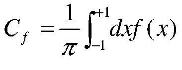
Figure 1 (d) .
f 0(x) is an object image in the part of PI line segment within the region B, as it falls outside the support of the object under examination and is usually the air, the image reconstruction value is generally set as 0. f max represents the possible maximum value in the reconstructed image, which can be set as an attenuation coefficient value of the material in the object having the maximum density according to the property of the object. For instance, in a medical CT imaging, the object under examination is usually human beings and the maximum value of the reconstructed image is generally that of the bone tissues, so f max can be set as an attenuation coefficient value of the bone tissues under corresponding X-ray energy.
g(x) is a one dimensional Hilbert transform value in the PI line segment, i.e., the result of difference calculation of the projection data and then back projection to the PI line segment, which can be calculated by the following formula:
r 0 is a two dimensional coordinate representation in the slice image space of a point in the one dimensional PI line and represents asr 0 = (cosφ0, sinφ0), and in one-to-one correspondence with the point x in g(x), wherein p(s,φ) represents the projection data, s is the one dimensional coordinate in the detector, φ s the angle of the projection,u (φ)=(cos φ, sin φ). In this case, g(x) and b(r 0) have the same meaning, and are only represented as different variants as they are in different coordinate systems. - It may be easy to understand and to implement the constraint conditions C 2,C 4,C 5 in formula (1), and condition C 1 can be implemented by POCS (Projection onto Convex Set) iterative calculation. Specifically, condition C 1 can be implemented by the following iterative calculation:


- g̃k (x) in formula (3) is defined as:

- The formula for calculating the constraint condition C 3 in formula (1) is:

- Based on the description of the specific processing of solving formula (1), it can be known that in the seeking for the intersection function fulfilling all the five constraints in formula (1), it is necessary to perform back projection filtration first (i.e., to acquire the value of g(x)), and then to acquire the value of f(
r ) by POCS iterative calculation.. AS the POCS iterative procedure is always a repeated iteration between the reconstruction image domain and the Hilbert transform space and there is no problem of forward projection, the speed of image reconstruction is very fast. - Specifically, in step S303, one PI line segment is selected from the group of PI line segments. Then in step S305, a one dimensional Hilbert transform value of the selected PI line segment is calculated, which can be obtained in accordance with formula (2). Subsequently, in step S307, limit inverse Hilbert transform is performed for the one dimensional Hilbert transform value calculated in step S305 to acquire the reconstruction image value of the PI line segment. In the processing of step S307, a repeated iteration, i.e., the POCS iterative procedure, between the reconstruction image domain and the Hilbert transform space domain is required to acquire a reconstruction image satisfying the accuracy requirement. The processing of step S307 can be performed in accordance with formulas (1) and (3)-(6).
- It should be noted that the above reconstruction method is not limited to a certain scanning manner, and it can be applicable to the CT scanning using parallel beam, sector beam or cone beam X-ray. Meanwhile, the reconstruction method is also applicable to different scanning traces, and the only difference lies in that the back projection formula (2) may change slightly in the weight coefficient due to the variation of the specific scanning manner, which only needs to make corresponding adjustments according to the specific scanning manner, so it will not be discussed any more.
- Moreover, it should also be pointed out that
Figure 3 only provides a specific manner of reconstructing the CT image of the ROI in accordance with the CT projection data of the ROI and the region B. Other methods utilizing the CT projection data of the ROI and the region B in light of the principle of the present invention may also be applicable, and all these methods fall within the protection scope of the present invention. -
Figure 4 shows a CT imaging device 400 according to an embodiment of the present invention, which performs CT imaging using the CT imaging method according to the present invention. The CT imaging device 400 comprises anX-ray generator 410 for generating an X-ray beam for use in scanning, afront collimator 420,detector arrangement 430, adetector position controller 440, arotation mechanism 450, acarrier 460 of the object under examination, amain controller 470, adata processor 480 anddisplay device 490. - The X-ray emitted from the
X-ray generator 410 is usually a sector beam (corresponding to a linear array detector) or a cone beam (corresponding to a planar array detector). Thefront collimator 420 is mounted at the position of an emergence window of theX-ray generator 410 for limiting the width of the X-ray beam, such that the width of the X-ray beam is consistent with the width of the detector in the detector arrangement. As stated in the CT imaging method described above, it is required to respective scan of the ROI and the region B, so it is necessary that thefront collimator 420 has the function of adjusting the width of the X-ray beam such that the X-ray beam only covers the ROI or the region B.Figure 5 shows the detailed structure of thefront collimator 420. As shown inFigure 5(a) , thefront collimator 420 is composed of fourX-ray shielding blocks 421a-421d, forming anX-ray emergence window 423 of a certain shape, which can be circular, rectangular or other shapes. In this embodiment, as shown inFigure 5(b) , a rectangle is illustrated as an example. TheX-ray shielding blocks 421a-421d are made of substances capable of effectively absorbing X-ray energy (which can be high density materials such as lead, tungsten etc.), and are thick enough to block the penetration of X-ray. EachX-ray shielding blocks 421a-421d is provided with a set ofservo motors 425 and precision lead screws 427 operating independently and located behind of the blocks (as shown inFigure 5(c) ). Theservo motor 425 and theprecision lead screw 427 are capable of, driving correspondingX-ray shielding blocks 421a-421d to move forward or backward along theprecision lead screw 427 in accordance with given parameters under the control of themain controller 470. As long as four sets ofservo motor 425 andprecision lead screw 427 operate simultaneously in accordance with the given parameters, theX-ray emergence window 423 will be able to change the size and position of the window correspondingly with respect to different ROI or region B, so as to meet the requirement that the X-ray only covers the ROI or the region B during the scanning. Of course, the number of the X-ray shielding blocks is not necessarily four, and any X-ray shielding blocks capable of forming an X-ray emergence window of a certain shape can fall within the protection scope of the present invention. - The
detector arrangement 430 can adapt a linear array of detectors or a planar array of detectors, or a flat-panel detector with corresponding auxiliary devices. Thedetector arrangement 430 detects the X-ray passing through the scanned region to produce projection data and transmits the projection data to thedata processor 480 for further processing by optical fiber cable, network cable, etc. wire or wirelessly. - The
detector position controller 440 is used to control the position of thedetector arrangement 430, and include theservo motor 441 and theprecision lead screw 443 and so on.Figure 6 explains the detailed structure of thedetector position controller 440 in an embodiment where thedetector arrangement 430 is a planar array detector. As shown inFigure 6 , thedetector arrangement 430 is fixed to theprecision lead screw 443 by means of a card slot, and theservo motor 441 drives thedetector arrangement 430 to move in a straight line along thelead screw 443 under the control of themain controller 470. Since both the ROI and the region B are required to be selectable, it is necessary that scope of the movement of thedetector arrangement 430 covers any selectable positions in the ROI and the region B. Therefore, it is possible that the position of thedetector arrangement 430 is variable for each X-ray projection angle so as to change the position of the detector means 430 under the control of the main controller 270 as appropriate. - The
rotation mechanism 450 comprises a can frame capable of rotating around a certain fixed center. TheX-ray generator 410, thefront collimator 420, thedetector arrangement 430, thedetector position controller 440, etc. are all mounted to the can frame. In the CT scanning, the can frame rotates together with the above components under the control of themain controller 470, and during the rotation, theX-ray generator 410 emits at different angles X-ray that passes through the region under examination (for instance the ROI or the region B) and is detected by thedetector arrangement 430 from which the projection data is transmitted to thedata processor 480 in the backend for processing. Therotation mechanism 450 can perform multi-loop rotating scanning, mono-loop rotating scanning or reciprocal multi-loop rotating scanning, as long as these scanning manners can enable the CT imaging device 400 to obtain enough projection data for image construction, and all these canning manners fall within the protection scope of the present invention. - The
carrier 460 of the object under examination carries the object under examination in and out of the CT imaging device 400, and its structure is similar to the current device. Usually, thecarrier 460 of the object under examination is located in the vicinity of the rotating center of therotation mechanism 450 and the ROI is usually a part of the object under examination. - The
main controller 470 controls the entire scanning procedure. In the embodiments of the present invention, themain controller 470 controls the CT imaging device 400 in a manner corresponding to the CT imaging method illustrated inFigure 2 . Themain controller 470 first controls thefront collimator 420 and thedetector position controller 440 based on the determined ROI such that the X-ray emitted from theX-ray generator 410 only covers the ROI. Then themain controller 470 controls the CT imaging device 400 to perform CT scanning of the ROI to acquire the projection data of the ROI and transmit the data to thedata processor 480. Subsequently, themain controller 470 controls thefront collimator 420 and thedetector position controller 440 based on the determined region B such that the X-ray emitted from theX-ray generator 410 only covers the region B. Then, themain controller 470 controls the CT imaging device 400 to perform CT scanning of the region B to acquire the projection data of the region B and transmit the data to thedata processor 480. - After the
data processor 480 has acquired the projection data of the ROI and the region B, it reconstructs the image of the ROI in accordance with the reconstruction method illustrated inFigure 3 . Specifically, the data processor comprises PIline division unit 481, Hilbert transformcalculation unit 483, inverse Hilbert transformcalculation unit 485 and data reconstruction combination unit 487, wherein the PIline division unit 481 selects a group of PI line segments that can cover the ROI depending on the relative position of the ROI and the region B, and ensures that each PI line passing through the ROI also passes through the region B. The Hilberttransform calculation unit 483 calculates a one dimensional Hilbert transform value along the PI line for each PI line in the group. The inverse Hilbert transformcalculation unit 485 performs limit inverse Hilbert transform for the one dimensional Hilbert transform value calculated by the Hilbert transformcalculation unit 483, so as to acquire the reconstruction image values of the PI line segment, wherein in the inverse Hilbert transformcalculation unit 485, a repeated iteration, i.e., the POCS iterative procedure, between the reconstruction image domain and the Hilbert transform space domain is required to acquire a reconstruction image satisfying the accuracy requirement. The data reconstruction combination unit 487 combines the reconstruction images calculated by the inverse Hilbert transformcalculation unit 485 for each PI line in the group with respect to the group of PI lines provided by the PIline division unit 481 to obtain the result ROI image. The details of the processing in thedata processor 480 have been discussed above, and hence it will not be discussed any more. - In addition, the
data processor 480 further performs image data processing executed in traditional imaging device and CT scanning such as rigidification, scattering correction, metal artifacts correction and image processing and pattern recognization. - The
display device 490 displays the reconstructed ROI image and it can further display information related to the control and the parameters during the CT scanning such that the operator can acquire the above information directly. - The CT imaging device 400 according to the present invention can reconstruct the ROI image rapidly and exactly by scanning the ROI and the region B respectively. Although two times of CT scanning are involved, only the ROI and the region B are to be scanned, so the scanning and reconstruction speed is improved instead. Beside, the region of the object under examination is less exposed to X-ray significantly.
- It should be pointed out that although in the description of the embodiment with respect to the CT imaging device 400, the CT projection data of the ROI is acquired before the CT projection data of the region B being acquired, but this sequence can be arbitrary, for instance, the CT projection data of the region B can be acquired before the CT projection data of the ROI being acquired. Or even, in an embodiment according to the present invention, the CT projection data of the ROI and the region B can be acquired simultaneously. All these manners of acquiring the CT projection data of the ROI and the region B fall within the protection scope of the present invention.
Figure 7 shows the numerical simulation results of CT image scanning and reconstruction with the CT imaging device according to the present invention. In the experiment, we adopted a Shepp-logan head model, which was constrained in a circle with a diameter of 20cm. The ROI was a square of side 6cm placed at the center of the head model. Two elongated rectangles B1 and B2 were placed at the location of x = ±8.0cm respectively. It can be known from the definition of the head model that the image values in the elongated rectangles B1 and B2 are both 0. When the ROI underwent the CT scanning, a parallel beam X-ray only covers the ROI and the regions B1 and B2 during the 180 degree scanning, as shown inFigure 7(a). Figure 7(b) is an ROI image reconstructed with the projection data passing through the ROI and the regions B1 and B2 using the image reconstruction method according to the present invention; andFigure 7(c) is an ROI image reconstructed only with the projection data passing through the ROI and the region B1 using the image reconstruction algorithm according to the present invention. It can be seen from the reconstruction results of (b) and (c) that with the CT imaging method of the present invention, an ROI image of high quality can be reconstructed when the X-ray only covers the ROI and a further small region outside of the object, which ROI image can satisfy the requirement of engineering applications. Furthermore, this CT imaging technique can save the size of the detector, reduce the amount of the projection data and improve the speed of CT image reconstruction to a considerable degree. What is more important, it can greatly decrease the X-ray radiation dose exposed on the object/patient while ensuring the quality of the ROI CT image, which is significant for medical CT imaging. - It should be noted that in the CT imaging device according to the present invention, components therein are logically divided in light of the functions to be achieved. However, the present invention is not limited by this and the components of the CT imaging device can be redivided or recombined upon needs, for instance, some components can be combined as an individual component or some components can be further divided into more sub-components.
- The embodiments of the present invention can be carried out by hardware or by software modules run on one or more processors, or by the combination thereof. One skilled in the art should understand that microprocessors or digital signal processors (DSP) can be used in practice to carry out some or all of the functions of some or all of the components of the CT imaging device according to the embodiments of the present invention. The present invention can further be implemented as device or means programs (for example, computer programs and computer program products) for executing part or all of the method described herein. Such programs carrying out the present invention can be stored in a computer-readable medium, or have the form of one or more signals. Such signals can be downloaded from Internet websites or provided by a carrier signal or provided in any other forms.
- It should be noted that the above embodiments illustrate rather than limit the invention, and that those skilled in the art will be able to design alternative embodiments without departing from the scope of the appended claims. In the claims, any reference signs placed between parentheses shall not be construed as limiting the claim. The word "comprise" does not exclude the existence of elements or steps other than those listed in a claim. The word "a" or "an" preceding an element does not exclude the existence of a plurality of such elements. The present invention can be achieved by means of hardware comprising several different elements and by means of an appropriately programmed computer. In unit claims listing several means, several of these means can be embodied by one and the same item of hardware. The use of ordinal words such as first, second and third does not represent any order, but instead, they can be understood as titles.
Claims (14)
- A method of CT imaging a region of interest of an object under examination, comprising:acquiring CT projection data of the region of interest;acquiring CT projection data of a region B, wherein at least a part of the region B falls outside the support of the object, and wherein the region B is selected to enable the selection of a group of PI line segments covering the region of interest, and each PI line segment passing through the region of interest passes through the region B; andreconstructing the CT image of the region of interest in accordance with the CT projection data of the region of interest and the region B.
- The CT imaging method according to claim 1, wherein the reconstruction of the CT image of the region of interest in accordance with the CT projection data of the region of interest and the region B comprises steps of:For each PI line segment in the group of PI line segments:calculating a one dimensional Hilbert transform value of the PI line segment, andperforming a limit inverse Hilbert transform for the one dimensional Hilbert transform value to acquire the reconstruction image value of the PI line segment;combining the reconstruction image values in all the PI lines in the group of PI line segments to obtain the image of the region of interest.
- The CT imaging method according to claim 1, wherein the limit inverse Hilbert transform comprises the step of:performing a Projection onto Convex Set (POCS) iteration between the reconstruction image domain and the Hilbert transform space domain to acquire a reconstruction image in the PI line segment that satisfies the accuracy requirement.
- The CT imaging method according to claim 1, wherein the acquisition of the CT projection data of the region of interest and the acquisition of the CT projection data of the region B comprise:performing CT scanning of the region of interest and the region B with parallel beam, sector beam or cone beam X-ray to acquire the CT projection data of the region of interest and the region B.
- A CT imaging device for CT imaging a region of interest of an object under examination, comprising:an X-ray generator being configured to generate an X-ray beam for use in scanning;a detector arrangement being configured to detect the X-ray passing through the scanned region so as to produce projection data;a carrier of the object being configured to carry the object under examination in andout of the CT imaging device;a main controller being configured to control the operation of the CT imaging device,such that the X-ray emitted from the X-ray generator only covers the region of interest so as to obtain the projection data of the region of interest, and such that the X-ray emitted from the X-ray generator only covers the region B so as to obtain the projection data of the region B, wherein the region B falls outside the support of the object under examination, and wherein the region B is selected to enable the selection of a group of PI line segments covering the region of interest, wherein each PI line segment passing through the region of interest also passes through the region B; anda data processor being configured to reconstruct the image of the region of interest in accordance with the obtained projection data of the region of interest and the region B.
- The CT imaging device according to claim 5, wherein the data processor comprises:a PI line division unit being configured to provide a group of PI line segments covering the region of interest;a Hilbert transform calculation unit being configured to calculate a one dimensional Hilbert transform value along the PI line segment for each PI line segment in the group of PI line segments;an inverse Hilbert transform calculation unit being configured to perform limit inverse Hilbert transform for the one dimensional Hilbert transform value calculated by the Hilbert transform calculation unit, so as to acquire the reconstruction image value in the PI line segment; anda data reconstruction combination unit being configured to combine the reconstruction images calculated by the inverse Hilbert transform calculation unit for each PI line to obtain the image of the region of interest.
- The CT imaging device according to claim 6, wherein the inverse Hilbert transform calculation unit performs a Projection onto Convex Set (POCS) iteration between the reconstruction image domain and the Hilbert transform space domain to acquire a reconstruction image for the PI line segment that satisfies the accuracy requirement.
- The CT imaging device according to claim 5, further comprising:a front collimator being configured to adjust the width of the X-ray beam under the control of the main controller such that the X-ray beam only covers the region of interest or the region B.
- The CT imaging device according to claim 5, further comprising:a detector position controller being configured to control the position of the detector means such that the movement scope of the detector means can cover the positions of the region of interest and the region B.
- The CT imaging device according to claim 8, wherein the front collimator comprises a plurality of X-ray shielding blocks forming an X-ray emergence window of a certain shape, which X-ray shielding blocks can cooperate to change the size and the position of the X-ray emergence window.
- The CT imaging device according to claim 10, wherein the front collimator comprises four X-ray shielding blocks, each of which is controlled by a set of servo motors and precision lead screws operating independently, such that the X-ray shielding blocks move along the precision lead screw.
- The CT imaging device according to claim 9, wherein the detector position controller comprises a servo motor and a precision lead screw, wherein the detector arrangement is fixed on the precision lead screw so that it is driven by the servo motor to move along the precision lead screw.
- A computer program product, comprising instructions for implementing the steps of the method according to claim 1 when loaded to a computer and operated thereon.
- A recording medium which stores instructions for implementing the steps of the method according to claims 1 when loaded to a computer and operated thereon.
Applications Claiming Priority (2)
| Application Number | Priority Date | Filing Date | Title |
|---|---|---|---|
| CN200910085612.4A CN101897593B (en) | 2009-05-26 | 2009-05-26 | A computer tomography device and method |
| PCT/CN2009/001593 WO2010135855A1 (en) | 2009-05-26 | 2009-12-30 | Computer tomography imaging device and method |
Publications (3)
| Publication Number | Publication Date |
|---|---|
| EP2436312A1 true EP2436312A1 (en) | 2012-04-04 |
| EP2436312A4 EP2436312A4 (en) | 2013-07-24 |
| EP2436312B1 EP2436312B1 (en) | 2021-03-03 |
Family
ID=43222106
Family Applications (1)
| Application Number | Title | Priority Date | Filing Date |
|---|---|---|---|
| EP09845074.5A Not-in-force EP2436312B1 (en) | 2009-05-26 | 2009-12-30 | Computer tomography imaging device and method |
Country Status (4)
| Country | Link |
|---|---|
| US (1) | US9380984B2 (en) |
| EP (1) | EP2436312B1 (en) |
| CN (1) | CN101897593B (en) |
| WO (1) | WO2010135855A1 (en) |
Cited By (1)
| Publication number | Priority date | Publication date | Assignee | Title |
|---|---|---|---|---|
| CN118898284A (en) * | 2024-10-09 | 2024-11-05 | 福建自贸试验区厦门片区Manteia数据科技有限公司 | Medical imaging-based model training method, device and storage medium |
Families Citing this family (183)
| Publication number | Priority date | Publication date | Assignee | Title |
|---|---|---|---|---|
| US10893912B2 (en) | 2006-02-16 | 2021-01-19 | Globus Medical Inc. | Surgical tool systems and methods |
| US10653497B2 (en) | 2006-02-16 | 2020-05-19 | Globus Medical, Inc. | Surgical tool systems and methods |
| US10357184B2 (en) | 2012-06-21 | 2019-07-23 | Globus Medical, Inc. | Surgical tool systems and method |
| WO2012131660A1 (en) | 2011-04-01 | 2012-10-04 | Ecole Polytechnique Federale De Lausanne (Epfl) | Robotic system for spinal and other surgeries |
| CN103175854B (en) * | 2011-12-22 | 2015-07-08 | 首都师范大学 | System and method for scanning X-ray faultage by electronic computer |
| US10799298B2 (en) | 2012-06-21 | 2020-10-13 | Globus Medical Inc. | Robotic fluoroscopic navigation |
| US11253327B2 (en) | 2012-06-21 | 2022-02-22 | Globus Medical, Inc. | Systems and methods for automatically changing an end-effector on a surgical robot |
| US12329593B2 (en) | 2012-06-21 | 2025-06-17 | Globus Medical, Inc. | Surgical robotic automation with tracking markers |
| US11317971B2 (en) | 2012-06-21 | 2022-05-03 | Globus Medical, Inc. | Systems and methods related to robotic guidance in surgery |
| US12310683B2 (en) | 2012-06-21 | 2025-05-27 | Globus Medical, Inc. | Surgical tool systems and method |
| US11963755B2 (en) | 2012-06-21 | 2024-04-23 | Globus Medical Inc. | Apparatus for recording probe movement |
| US12446981B2 (en) | 2012-06-21 | 2025-10-21 | Globus Medical, Inc. | System and method for surgical tool insertion using multiaxis force and moment feedback |
| WO2013192598A1 (en) | 2012-06-21 | 2013-12-27 | Excelsius Surgical, L.L.C. | Surgical robot platform |
| US12004905B2 (en) | 2012-06-21 | 2024-06-11 | Globus Medical, Inc. | Medical imaging systems using robotic actuators and related methods |
| US11857149B2 (en) | 2012-06-21 | 2024-01-02 | Globus Medical, Inc. | Surgical robotic systems with target trajectory deviation monitoring and related methods |
| US11116576B2 (en) | 2012-06-21 | 2021-09-14 | Globus Medical Inc. | Dynamic reference arrays and methods of use |
| US11395706B2 (en) | 2012-06-21 | 2022-07-26 | Globus Medical Inc. | Surgical robot platform |
| US10624710B2 (en) | 2012-06-21 | 2020-04-21 | Globus Medical, Inc. | System and method for measuring depth of instrumentation |
| US11864839B2 (en) | 2012-06-21 | 2024-01-09 | Globus Medical Inc. | Methods of adjusting a virtual implant and related surgical navigation systems |
| US11298196B2 (en) | 2012-06-21 | 2022-04-12 | Globus Medical Inc. | Surgical robotic automation with tracking markers and controlled tool advancement |
| US10350013B2 (en) | 2012-06-21 | 2019-07-16 | Globus Medical, Inc. | Surgical tool systems and methods |
| US10136954B2 (en) | 2012-06-21 | 2018-11-27 | Globus Medical, Inc. | Surgical tool systems and method |
| US11045267B2 (en) | 2012-06-21 | 2021-06-29 | Globus Medical, Inc. | Surgical robotic automation with tracking markers |
| US20150032164A1 (en) | 2012-06-21 | 2015-01-29 | Globus Medical, Inc. | Methods for Performing Invasive Medical Procedures Using a Surgical Robot |
| US10646280B2 (en) | 2012-06-21 | 2020-05-12 | Globus Medical, Inc. | System and method for surgical tool insertion using multiaxis force and moment feedback |
| US12472008B2 (en) | 2012-06-21 | 2025-11-18 | Globus Medical, Inc. | Robotic fluoroscopic navigation |
| US12220120B2 (en) | 2012-06-21 | 2025-02-11 | Globus Medical, Inc. | Surgical robotic system with retractor |
| US10842461B2 (en) | 2012-06-21 | 2020-11-24 | Globus Medical, Inc. | Systems and methods of checking registrations for surgical systems |
| US11786324B2 (en) | 2012-06-21 | 2023-10-17 | Globus Medical, Inc. | Surgical robotic automation with tracking markers |
| US11864745B2 (en) | 2012-06-21 | 2024-01-09 | Globus Medical, Inc. | Surgical robotic system with retractor |
| US11896446B2 (en) | 2012-06-21 | 2024-02-13 | Globus Medical, Inc | Surgical robotic automation with tracking markers |
| US12262954B2 (en) | 2012-06-21 | 2025-04-01 | Globus Medical, Inc. | Surgical robotic automation with tracking markers |
| US10231791B2 (en) | 2012-06-21 | 2019-03-19 | Globus Medical, Inc. | Infrared signal based position recognition system for use with a robot-assisted surgery |
| US10758315B2 (en) | 2012-06-21 | 2020-09-01 | Globus Medical Inc. | Method and system for improving 2D-3D registration convergence |
| US10874466B2 (en) | 2012-06-21 | 2020-12-29 | Globus Medical, Inc. | System and method for surgical tool insertion using multiaxis force and moment feedback |
| US11974822B2 (en) | 2012-06-21 | 2024-05-07 | Globus Medical Inc. | Method for a surveillance marker in robotic-assisted surgery |
| US11589771B2 (en) | 2012-06-21 | 2023-02-28 | Globus Medical Inc. | Method for recording probe movement and determining an extent of matter removed |
| US11793570B2 (en) | 2012-06-21 | 2023-10-24 | Globus Medical Inc. | Surgical robotic automation with tracking markers |
| US11399900B2 (en) | 2012-06-21 | 2022-08-02 | Globus Medical, Inc. | Robotic systems providing co-registration using natural fiducials and related methods |
| US11607149B2 (en) | 2012-06-21 | 2023-03-21 | Globus Medical Inc. | Surgical tool systems and method |
| US12594001B2 (en) | 2012-06-21 | 2026-04-07 | Globus Medical, Inc. | Apparatus for recording probe movement |
| US12465433B2 (en) | 2012-06-21 | 2025-11-11 | Globus Medical Inc. | Methods of adjusting a virtual implant and related surgical navigation systems |
| US11857266B2 (en) | 2012-06-21 | 2024-01-02 | Globus Medical, Inc. | System for a surveillance marker in robotic-assisted surgery |
| JP6370297B2 (en) * | 2012-09-07 | 2018-08-08 | トロフィー | Device for partial CT imaging |
| CN103675931B (en) | 2012-09-26 | 2016-09-28 | 同方威视技术股份有限公司 | CT system and the detection device for CT system |
| CN104182932B (en) * | 2013-05-27 | 2017-04-12 | 株式会社日立制作所 | CT (Computed Tomography) device, CT image system and CT image generation method |
| US9283048B2 (en) | 2013-10-04 | 2016-03-15 | KB Medical SA | Apparatus and systems for precise guidance of surgical tools |
| EP3094272B1 (en) | 2014-01-15 | 2021-04-21 | KB Medical SA | Notched apparatus for guidance of an insertable instrument along an axis during spinal surgery |
| US10039605B2 (en) | 2014-02-11 | 2018-08-07 | Globus Medical, Inc. | Sterile handle for controlling a robotic surgical system from a sterile field |
| CN106659537B (en) | 2014-04-24 | 2019-06-11 | Kb医疗公司 | Surgical Instrument Holders for Use with Robotic Surgical Systems |
| CN103961131B (en) * | 2014-05-27 | 2015-12-30 | 赛诺威盛科技(北京)有限公司 | A kind of arc beam-defining clipper shielding plate structure |
| US10828120B2 (en) | 2014-06-19 | 2020-11-10 | Kb Medical, Sa | Systems and methods for performing minimally invasive surgery |
| US10357257B2 (en) | 2014-07-14 | 2019-07-23 | KB Medical SA | Anti-skid surgical instrument for use in preparing holes in bone tissue |
| US10765438B2 (en) | 2014-07-14 | 2020-09-08 | KB Medical SA | Anti-skid surgical instrument for use in preparing holes in bone tissue |
| KR101795605B1 (en) * | 2014-08-28 | 2017-11-08 | 삼성전자주식회사 | Medical image apparatus and operation method of the same |
| CN104287768A (en) * | 2014-09-30 | 2015-01-21 | 沈阳东软医疗系统有限公司 | Method and system for controlling CT scan dose |
| WO2016087539A2 (en) | 2014-12-02 | 2016-06-09 | KB Medical SA | Robot assisted volume removal during surgery |
| US10013808B2 (en) | 2015-02-03 | 2018-07-03 | Globus Medical, Inc. | Surgeon head-mounted display apparatuses |
| US10555782B2 (en) | 2015-02-18 | 2020-02-11 | Globus Medical, Inc. | Systems and methods for performing minimally invasive spinal surgery with a robotic surgical system using a percutaneous technique |
| US10082473B2 (en) | 2015-07-07 | 2018-09-25 | General Electric Company | X-ray filtration |
| US10646298B2 (en) | 2015-07-31 | 2020-05-12 | Globus Medical, Inc. | Robot arm and methods of use |
| US10058394B2 (en) | 2015-07-31 | 2018-08-28 | Globus Medical, Inc. | Robot arm and methods of use |
| US10080615B2 (en) | 2015-08-12 | 2018-09-25 | Globus Medical, Inc. | Devices and methods for temporary mounting of parts to bone |
| WO2017037127A1 (en) | 2015-08-31 | 2017-03-09 | KB Medical SA | Robotic surgical systems and methods |
| US10034716B2 (en) | 2015-09-14 | 2018-07-31 | Globus Medical, Inc. | Surgical robotic systems and methods thereof |
| US9771092B2 (en) | 2015-10-13 | 2017-09-26 | Globus Medical, Inc. | Stabilizer wheel assembly and methods of use |
| WO2017103037A1 (en) * | 2015-12-17 | 2017-06-22 | Koninklijke Philips N.V. | Method and device for a medical image analysis |
| US10117632B2 (en) | 2016-02-03 | 2018-11-06 | Globus Medical, Inc. | Portable medical imaging system with beam scanning collimator |
| US10448910B2 (en) | 2016-02-03 | 2019-10-22 | Globus Medical, Inc. | Portable medical imaging system |
| US11058378B2 (en) | 2016-02-03 | 2021-07-13 | Globus Medical, Inc. | Portable medical imaging system |
| US11883217B2 (en) | 2016-02-03 | 2024-01-30 | Globus Medical, Inc. | Portable medical imaging system and method |
| US10842453B2 (en) | 2016-02-03 | 2020-11-24 | Globus Medical, Inc. | Portable medical imaging system |
| US10866119B2 (en) | 2016-03-14 | 2020-12-15 | Globus Medical, Inc. | Metal detector for detecting insertion of a surgical device into a hollow tube |
| EP3241518B1 (en) | 2016-04-11 | 2024-10-23 | Globus Medical, Inc | Surgical tool systems |
| US11039893B2 (en) | 2016-10-21 | 2021-06-22 | Globus Medical, Inc. | Robotic surgical systems |
| CN106534866A (en) * | 2016-11-25 | 2017-03-22 | 中北大学 | Image compression method and apparatus |
| CN106683142B (en) * | 2016-12-28 | 2020-03-13 | 上海联影医疗科技有限公司 | Dynamic pitch CT image reconstruction method and device |
| EP3360502A3 (en) | 2017-01-18 | 2018-10-31 | KB Medical SA | Robotic navigation of robotic surgical systems |
| JP7583513B2 (en) | 2017-01-18 | 2024-11-14 | ケービー メディカル エスアー | Universal instrument guide for robotic surgical systems, surgical instrument system |
| EP3351202B1 (en) | 2017-01-18 | 2021-09-08 | KB Medical SA | Universal instrument guide for robotic surgical systems |
| US11071594B2 (en) | 2017-03-16 | 2021-07-27 | KB Medical SA | Robotic navigation of robotic surgical systems |
| US20180289432A1 (en) | 2017-04-05 | 2018-10-11 | Kb Medical, Sa | Robotic surgical systems for preparing holes in bone tissue and methods of their use |
| US11135015B2 (en) | 2017-07-21 | 2021-10-05 | Globus Medical, Inc. | Robot surgical platform |
| CN107582089B (en) * | 2017-09-29 | 2021-06-29 | 上海联影医疗科技股份有限公司 | Collimator, imaging device, focus position tracking method and correction method |
| US12544109B2 (en) | 2017-11-09 | 2026-02-10 | Globus Medical, Inc. | Robotic rod benders and related mechanical and motor housings |
| JP6778242B2 (en) | 2017-11-09 | 2020-10-28 | グローバス メディカル インコーポレイティッド | Surgical robot systems for bending surgical rods, and related methods and equipment |
| US11794338B2 (en) | 2017-11-09 | 2023-10-24 | Globus Medical Inc. | Robotic rod benders and related mechanical and motor housings |
| US11382666B2 (en) | 2017-11-09 | 2022-07-12 | Globus Medical Inc. | Methods providing bend plans for surgical rods and related controllers and computer program products |
| US11134862B2 (en) | 2017-11-10 | 2021-10-05 | Globus Medical, Inc. | Methods of selecting surgical implants and related devices |
| CN108095745B (en) * | 2017-12-13 | 2020-12-04 | 上海联影医疗科技股份有限公司 | A medical imaging device and a method of acquiring an image for evaluating the performance of the medical imaging device |
| US20190254753A1 (en) | 2018-02-19 | 2019-08-22 | Globus Medical, Inc. | Augmented reality navigation systems for use with robotic surgical systems and methods of their use |
| US20190282189A1 (en) * | 2018-03-15 | 2019-09-19 | Accuray Incorporated | Limiting imaging radiation dose and improving image quality during treatment delivery |
| US11175242B2 (en) * | 2018-03-20 | 2021-11-16 | Fei Company | Geometric alignment, sample motion correction, and intensity normalization of computed tomography projections using pi-line optimization |
| US10573023B2 (en) | 2018-04-09 | 2020-02-25 | Globus Medical, Inc. | Predictive visualization of medical imaging scanner component movement |
| CN108593687B (en) * | 2018-04-27 | 2021-05-25 | 中国科学院高能物理研究所 | A fast defect detection method based on three-dimensional tomography |
| US10713824B2 (en) * | 2018-06-26 | 2020-07-14 | Uih America, Inc. | System and method for 3D image reconstruction from axial step-and-shoot CT |
| CN109124666A (en) * | 2018-06-29 | 2019-01-04 | 上海联影医疗科技有限公司 | A kind of mthods, systems and devices of determining dose of radiation modulation lines |
| US10888296B2 (en) | 2018-06-29 | 2021-01-12 | Shanghai United Imaging Healthcare Co., Ltd. | Methods and systems for modulating radiation dose |
| CN110693513B (en) * | 2018-10-27 | 2023-07-25 | 上海联影医疗科技股份有限公司 | Control method, system and storage medium of multi-mode medical system |
| US11337742B2 (en) | 2018-11-05 | 2022-05-24 | Globus Medical Inc | Compliant orthopedic driver |
| US11278360B2 (en) | 2018-11-16 | 2022-03-22 | Globus Medical, Inc. | End-effectors for surgical robotic systems having sealed optical components |
| US11744655B2 (en) | 2018-12-04 | 2023-09-05 | Globus Medical, Inc. | Drill guide fixtures, cranial insertion fixtures, and related methods and robotic systems |
| US11602402B2 (en) | 2018-12-04 | 2023-03-14 | Globus Medical, Inc. | Drill guide fixtures, cranial insertion fixtures, and related methods and robotic systems |
| CN109480876A (en) * | 2018-12-06 | 2019-03-19 | 宁波耀通管阀科技有限公司 | Spinal cord CT machine control platform |
| US11654304B2 (en) | 2018-12-17 | 2023-05-23 | Shanghai United Imaging Healthcare Co., Ltd. | Systems and methods for determining a region of interest of a subject |
| CN109540926B (en) * | 2019-01-29 | 2021-10-08 | 中国工程物理研究院激光聚变研究中心 | High-precision measuring device and measuring method of KDP or DKDP crystal damage performance |
| US11918313B2 (en) | 2019-03-15 | 2024-03-05 | Globus Medical Inc. | Active end effectors for surgical robots |
| US11382549B2 (en) | 2019-03-22 | 2022-07-12 | Globus Medical, Inc. | System for neuronavigation registration and robotic trajectory guidance, and related methods and devices |
| US11806084B2 (en) | 2019-03-22 | 2023-11-07 | Globus Medical, Inc. | System for neuronavigation registration and robotic trajectory guidance, and related methods and devices |
| US11317978B2 (en) | 2019-03-22 | 2022-05-03 | Globus Medical, Inc. | System for neuronavigation registration and robotic trajectory guidance, robotic surgery, and related methods and devices |
| US11419616B2 (en) | 2019-03-22 | 2022-08-23 | Globus Medical, Inc. | System for neuronavigation registration and robotic trajectory guidance, robotic surgery, and related methods and devices |
| US20200297357A1 (en) | 2019-03-22 | 2020-09-24 | Globus Medical, Inc. | System for neuronavigation registration and robotic trajectory guidance, robotic surgery, and related methods and devices |
| US11571265B2 (en) | 2019-03-22 | 2023-02-07 | Globus Medical Inc. | System for neuronavigation registration and robotic trajectory guidance, robotic surgery, and related methods and devices |
| CN110301934B (en) * | 2019-08-14 | 2022-11-29 | 晓智未来(成都)科技有限公司 | System and method for adjusting light field area of part to be shot based on key point detection |
| US11045179B2 (en) | 2019-05-20 | 2021-06-29 | Global Medical Inc | Robot-mounted retractor system |
| US11628023B2 (en) | 2019-07-10 | 2023-04-18 | Globus Medical, Inc. | Robotic navigational system for interbody implants |
| US12527535B2 (en) | 2019-08-08 | 2026-01-20 | University Of Florida Research Foundation, Inc. | Focused tomography |
| US11801017B2 (en) * | 2019-08-08 | 2023-10-31 | University Of Florida Research Foundation, Inc. | Focused tomography |
| US12396692B2 (en) | 2019-09-24 | 2025-08-26 | Globus Medical, Inc. | Compound curve cable chain |
| US11571171B2 (en) | 2019-09-24 | 2023-02-07 | Globus Medical, Inc. | Compound curve cable chain |
| US12329391B2 (en) | 2019-09-27 | 2025-06-17 | Globus Medical, Inc. | Systems and methods for robot-assisted knee arthroplasty surgery |
| US11426178B2 (en) | 2019-09-27 | 2022-08-30 | Globus Medical Inc. | Systems and methods for navigating a pin guide driver |
| US11890066B2 (en) | 2019-09-30 | 2024-02-06 | Globus Medical, Inc | Surgical robot with passive end effector |
| US12408929B2 (en) | 2019-09-27 | 2025-09-09 | Globus Medical, Inc. | Systems and methods for navigating a pin guide driver |
| US11864857B2 (en) | 2019-09-27 | 2024-01-09 | Globus Medical, Inc. | Surgical robot with passive end effector |
| US11510684B2 (en) | 2019-10-14 | 2022-11-29 | Globus Medical, Inc. | Rotary motion passive end effector for surgical robots in orthopedic surgeries |
| CN110811663B (en) * | 2019-11-20 | 2024-03-26 | 上海联影医疗科技股份有限公司 | A multi-area scanning method, device, equipment and storage medium |
| US12220176B2 (en) | 2019-12-10 | 2025-02-11 | Globus Medical, Inc. | Extended reality instrument interaction zone for navigated robotic |
| US12133772B2 (en) | 2019-12-10 | 2024-11-05 | Globus Medical, Inc. | Augmented reality headset for navigated robotic surgery |
| US11992373B2 (en) | 2019-12-10 | 2024-05-28 | Globus Medical, Inc | Augmented reality headset with varied opacity for navigated robotic surgery |
| US12064189B2 (en) | 2019-12-13 | 2024-08-20 | Globus Medical, Inc. | Navigated instrument for use in robotic guided surgery |
| US11464581B2 (en) | 2020-01-28 | 2022-10-11 | Globus Medical, Inc. | Pose measurement chaining for extended reality surgical navigation in visible and near infrared spectrums |
| US11382699B2 (en) | 2020-02-10 | 2022-07-12 | Globus Medical Inc. | Extended reality visualization of optical tool tracking volume for computer assisted navigation in surgery |
| US12414752B2 (en) | 2020-02-17 | 2025-09-16 | Globus Medical, Inc. | System and method of determining optimal 3-dimensional position and orientation of imaging device for imaging patient bones |
| US11207150B2 (en) | 2020-02-19 | 2021-12-28 | Globus Medical, Inc. | Displaying a virtual model of a planned instrument attachment to ensure correct selection of physical instrument attachment |
| US11253216B2 (en) | 2020-04-28 | 2022-02-22 | Globus Medical Inc. | Fixtures for fluoroscopic imaging systems and related navigation systems and methods |
| US11510750B2 (en) | 2020-05-08 | 2022-11-29 | Globus Medical, Inc. | Leveraging two-dimensional digital imaging and communication in medicine imagery in three-dimensional extended reality applications |
| US11153555B1 (en) | 2020-05-08 | 2021-10-19 | Globus Medical Inc. | Extended reality headset camera system for computer assisted navigation in surgery |
| US11382700B2 (en) | 2020-05-08 | 2022-07-12 | Globus Medical Inc. | Extended reality headset tool tracking and control |
| US12070276B2 (en) | 2020-06-09 | 2024-08-27 | Globus Medical Inc. | Surgical object tracking in visible light via fiducial seeding and synthetic image registration |
| US11317973B2 (en) | 2020-06-09 | 2022-05-03 | Globus Medical, Inc. | Camera tracking bar for computer assisted navigation during surgery |
| US11382713B2 (en) | 2020-06-16 | 2022-07-12 | Globus Medical, Inc. | Navigated surgical system with eye to XR headset display calibration |
| US11877807B2 (en) | 2020-07-10 | 2024-01-23 | Globus Medical, Inc | Instruments for navigated orthopedic surgeries |
| US11793588B2 (en) | 2020-07-23 | 2023-10-24 | Globus Medical, Inc. | Sterile draping of robotic arms |
| US11464464B2 (en) * | 2020-07-24 | 2022-10-11 | International Business Machines Corporation | Internal and external proximate scanning |
| CN111839572A (en) * | 2020-08-26 | 2020-10-30 | 深圳先进技术研究院 | CT imaging system and imaging method thereof |
| JP7485574B2 (en) * | 2020-08-28 | 2024-05-16 | キヤノンメディカルシステムズ株式会社 | X-ray CT device, control method for X-ray CT device, and program |
| US11737831B2 (en) | 2020-09-02 | 2023-08-29 | Globus Medical Inc. | Surgical object tracking template generation for computer assisted navigation during surgical procedure |
| US11523785B2 (en) | 2020-09-24 | 2022-12-13 | Globus Medical, Inc. | Increased cone beam computed tomography volume length without requiring stitching or longitudinal C-arm movement |
| US11911112B2 (en) | 2020-10-27 | 2024-02-27 | Globus Medical, Inc. | Robotic navigational system |
| US12076091B2 (en) | 2020-10-27 | 2024-09-03 | Globus Medical, Inc. | Robotic navigational system |
| US11941814B2 (en) | 2020-11-04 | 2024-03-26 | Globus Medical Inc. | Auto segmentation using 2-D images taken during 3-D imaging spin |
| US11717350B2 (en) | 2020-11-24 | 2023-08-08 | Globus Medical Inc. | Methods for robotic assistance and navigation in spinal surgery and related systems |
| US12070286B2 (en) | 2021-01-08 | 2024-08-27 | Globus Medical, Inc | System and method for ligament balancing with robotic assistance |
| US12150728B2 (en) | 2021-04-14 | 2024-11-26 | Globus Medical, Inc. | End effector for a surgical robot |
| US12178523B2 (en) | 2021-04-19 | 2024-12-31 | Globus Medical, Inc. | Computer assisted surgical navigation system for spine procedures |
| CN115436989B (en) * | 2021-06-04 | 2025-08-29 | 同方威视技术股份有限公司 | Beam distribution detection device and beam distribution detection method |
| US12458454B2 (en) | 2021-06-21 | 2025-11-04 | Globus Medical, Inc. | Gravity compensation of end effector arm for robotic surgical system |
| US12484969B2 (en) | 2021-07-06 | 2025-12-02 | Globdus Medical Inc. | Ultrasonic robotic surgical navigation |
| US11857273B2 (en) | 2021-07-06 | 2024-01-02 | Globus Medical, Inc. | Ultrasonic robotic surgical navigation |
| US11439444B1 (en) | 2021-07-22 | 2022-09-13 | Globus Medical, Inc. | Screw tower and rod reduction tool |
| US12201375B2 (en) | 2021-09-16 | 2025-01-21 | Globus Medical Inc. | Extended reality systems for visualizing and controlling operating room equipment |
| US12184636B2 (en) | 2021-10-04 | 2024-12-31 | Globus Medical, Inc. | Validating credential keys based on combinations of credential value strings and input order strings |
| US12238087B2 (en) | 2021-10-04 | 2025-02-25 | Globus Medical, Inc. | Validating credential keys based on combinations of credential value strings and input order strings |
| US12602775B2 (en) | 2021-10-20 | 2026-04-14 | Globus Medical Inc. | Interpolation of medical images |
| US20230165639A1 (en) | 2021-12-01 | 2023-06-01 | Globus Medical, Inc. | Extended reality systems with three-dimensional visualizations of medical image scan slices |
| US11911115B2 (en) | 2021-12-20 | 2024-02-27 | Globus Medical Inc. | Flat panel registration fixture and method of using same |
| US12544146B2 (en) | 2022-02-11 | 2026-02-10 | Globus Medical, Inc. | Apparatus and method for removing circular trackers attached to a tracking array |
| US12103480B2 (en) | 2022-03-18 | 2024-10-01 | Globus Medical Inc. | Omni-wheel cable pusher |
| US12048493B2 (en) | 2022-03-31 | 2024-07-30 | Globus Medical, Inc. | Camera tracking system identifying phantom markers during computer assisted surgery navigation |
| US12394086B2 (en) | 2022-05-10 | 2025-08-19 | Globus Medical, Inc. | Accuracy check and automatic calibration of tracked instruments |
| JP2023168125A (en) * | 2022-05-13 | 2023-11-24 | 株式会社島津製作所 | X-ray CT device and tomographic image reconstruction method |
| JP2023168124A (en) * | 2022-05-13 | 2023-11-24 | 株式会社島津製作所 | X-ray ct apparatus and reconstruction method of tomographic image |
| CN114947915B (en) * | 2022-05-19 | 2025-04-18 | 国网河南省电力公司电力科学研究院 | CT local imaging method |
| US12161427B2 (en) | 2022-06-08 | 2024-12-10 | Globus Medical, Inc. | Surgical navigation system with flat panel registration fixture |
| US20240020840A1 (en) | 2022-07-15 | 2024-01-18 | Globus Medical, Inc. | REGISTRATION OF 3D and 2D IMAGES FOR SURGICAL NAVIGATION AND ROBOTIC GUIDANCE WITHOUT USING RADIOPAQUE FIDUCIALS IN THE IMAGES |
| US12226169B2 (en) | 2022-07-15 | 2025-02-18 | Globus Medical, Inc. | Registration of 3D and 2D images for surgical navigation and robotic guidance without using radiopaque fiducials in the images |
| US12318150B2 (en) | 2022-10-11 | 2025-06-03 | Globus Medical Inc. | Camera tracking system for computer assisted surgery navigation |
| US12502220B2 (en) | 2022-11-15 | 2025-12-23 | Globus Medical, Inc. | Machine learning system for spinal surgeries |
| DE102023204265B4 (en) * | 2023-05-09 | 2024-12-24 | Siemens Healthineers Ag | Method for generating a volume model of an object under examination, control device, X-ray device, computer program and electronically readable data carrier |
| CN118015129B (en) * | 2024-04-08 | 2024-07-09 | 深圳市大成精密设备股份有限公司 | Slice image reconstruction method and device, storage medium and electronic equipment |
| CN118447113B (en) * | 2024-04-24 | 2025-02-25 | 清华大学 | X-ray CT local imaging method, device and electronic equipment for expanding imaging field of view |
| CN119606403B (en) * | 2025-02-11 | 2025-04-25 | 赛诺威盛科技(北京)股份有限公司 | Collimator control method, device, equipment and medium in spiral scanning mode |
Family Cites Families (17)
| Publication number | Priority date | Publication date | Assignee | Title |
|---|---|---|---|---|
| US5323007A (en) * | 1992-02-07 | 1994-06-21 | Univ. Of Chicago Development Corp. Argonne National Laboratories | Method of recovering tomographic signal elements in a projection profile or image by solving linear equations |
| DE69425762T2 (en) * | 1993-06-09 | 2001-04-26 | Wisconsin Alumni Research Foundation, Madison | Radiation therapy system |
| US6385278B1 (en) * | 2000-04-28 | 2002-05-07 | Ge Medical Systems Global Technology Company, Llc | Method and apparatus for region of interest multislice CT scan |
| US6835278B2 (en) | 2000-07-07 | 2004-12-28 | Mattson Technology Inc. | Systems and methods for remote plasma clean |
| JP2002296021A (en) * | 2001-04-03 | 2002-10-09 | Futec Inc | Thickness measuring device |
| US6891178B2 (en) * | 2001-07-19 | 2005-05-10 | The Board Of Trustees Of The Lealand Stanford Junior University | Method for checking positional accuracy of the leaves of a multileaf collimator |
| CN1189132C (en) | 2002-07-11 | 2005-02-16 | 飞利浦(中国)投资有限公司 | CT machine |
| US7110490B2 (en) * | 2002-12-10 | 2006-09-19 | General Electric Company | Full field digital tomosynthesis method and apparatus |
| CN101023448A (en) * | 2004-02-10 | 2007-08-22 | 芝加哥大学 | Imaging system |
| US7394923B2 (en) * | 2004-02-10 | 2008-07-01 | The University Of Chicago | Imaging system for generating a substantially exact reconstruction of a region of interest |
| EP1759225B1 (en) * | 2004-06-09 | 2010-12-01 | Philips Intellectual Property & Standards GmbH | Computerized tomography method with helical relative movement and conical beam |
| WO2006116316A2 (en) * | 2005-04-22 | 2006-11-02 | University Of Chicago | Open source trajectory method and apparatus for interior imaging |
| US7477720B2 (en) * | 2005-06-28 | 2009-01-13 | University Of Utah Research Foundation | Cone-beam reconstruction using backprojection of locally filtered projections and X-ray CT apparatus |
| US20080118032A1 (en) | 2006-10-06 | 2008-05-22 | Graham Sean A | Optimized aperture selection imaging computed tomography system and method |
| JP2008206822A (en) * | 2007-02-27 | 2008-09-11 | Toshiba Corp | Radiation therapy equipment |
| US8306304B2 (en) * | 2009-08-31 | 2012-11-06 | Siemens Aktiengesellschaft | Precise image reconstruction of spiral CT images at optional pitch values |
| US8952333B2 (en) * | 2009-11-02 | 2015-02-10 | Virginia Tech Intellectual Properties, Inc. | Methods for improved single photon emission computed tomography using exact and stable region of interest reconstructions |
-
2009
- 2009-05-26 CN CN200910085612.4A patent/CN101897593B/en active Active
- 2009-12-30 WO PCT/CN2009/001593 patent/WO2010135855A1/en not_active Ceased
- 2009-12-30 EP EP09845074.5A patent/EP2436312B1/en not_active Not-in-force
- 2009-12-30 US US13/322,696 patent/US9380984B2/en not_active Expired - Fee Related
Cited By (1)
| Publication number | Priority date | Publication date | Assignee | Title |
|---|---|---|---|---|
| CN118898284A (en) * | 2024-10-09 | 2024-11-05 | 福建自贸试验区厦门片区Manteia数据科技有限公司 | Medical imaging-based model training method, device and storage medium |
Also Published As
| Publication number | Publication date |
|---|---|
| CN101897593A (en) | 2010-12-01 |
| CN101897593B (en) | 2014-08-13 |
| EP2436312A4 (en) | 2013-07-24 |
| HK1150016A1 (en) | 2011-10-28 |
| US9380984B2 (en) | 2016-07-05 |
| WO2010135855A1 (en) | 2010-12-02 |
| EP2436312B1 (en) | 2021-03-03 |
| US20120140874A1 (en) | 2012-06-07 |
Similar Documents
| Publication | Publication Date | Title |
|---|---|---|
| EP2436312B1 (en) | Computer tomography imaging device and method | |
| JP5221394B2 (en) | How to reconstruct image functions from radon data | |
| CN102525527B (en) | The data for projection method of weighting of CT imaging | |
| US9775582B2 (en) | Medical image photographing apparatus and method of processing medical image | |
| JP5898081B2 (en) | X-ray CT system | |
| KR20120055468A (en) | Image processing apparatus, image processing method, and non-transitory storage medium | |
| US20070019776A1 (en) | Computer tomography method using a cone-shaped bundle of rays | |
| JP2016049455A (en) | X-ray computed tomography apparatus and image reconstruction apparatus | |
| EP1800264B1 (en) | Image reconstruction with voxel dependent interpolation | |
| CN1722983A (en) | Computed tomography scanning | |
| US20090154639A1 (en) | System and method for image reconstruction for helical cone beam computed tomography with factorized redundancy weighting | |
| US7187747B2 (en) | Computerized tomography method with helical relative movement and conical beam | |
| EP1570435B1 (en) | Method and apparatus for exact cone beam computed tomography | |
| JP2004113271A (en) | Ct scanner | |
| Tan et al. | Physical phantom studies of helical cone‐beam CT with exact reconstruction | |
| US9737277B2 (en) | X-ray CT system and medical image processing method | |
| CN103584877B (en) | A kind of computer chromatography imaging device and method | |
| CN101023448A (en) | Imaging system | |
| Choi et al. | A hybrid approach to reduce cone-beam artifacts for a circular orbit cone-beam CT system | |
| Alonzi et al. | Medical uses of computerized tomography (CT) scans and simple physical principles New evaluation of the radiology department | |
| Saito et al. | Development and evaluation of a real-time three-dimensional CT (4D-CT) scanner | |
| HK1150016B (en) | Computer tomography imaging device and method | |
| HK1194943A (en) | A computerized tomographic imaging device and method | |
| HK1194943B (en) | A computerized tomographic imaging device and method | |
| Feng et al. | A Feldkamp-Type Approach to Limited-Angle On-Board Three-Dimensional Imaging for External Beam Radiotherapy Target Localization |
Legal Events
| Date | Code | Title | Description |
|---|---|---|---|
| PUAI | Public reference made under article 153(3) epc to a published international application that has entered the european phase |
Free format text: ORIGINAL CODE: 0009012 |
|
| 17P | Request for examination filed |
Effective date: 20111223 |
|
| AK | Designated contracting states |
Kind code of ref document: A1 Designated state(s): AT BE BG CH CY CZ DE DK EE ES FI FR GB GR HR HU IE IS IT LI LT LU LV MC MK MT NL NO PL PT RO SE SI SK SM TR |
|
| DAX | Request for extension of the european patent (deleted) | ||
| A4 | Supplementary search report drawn up and despatched |
Effective date: 20130620 |
|
| RIC1 | Information provided on ipc code assigned before grant |
Ipc: A61B 6/00 20060101AFI20130614BHEP Ipc: A61B 6/06 20060101ALI20130614BHEP Ipc: G06T 11/00 20060101ALI20130614BHEP Ipc: A61B 6/03 20060101ALI20130614BHEP |
|
| 17Q | First examination report despatched |
Effective date: 20150529 |
|
| STAA | Information on the status of an ep patent application or granted ep patent |
Free format text: STATUS: EXAMINATION IS IN PROGRESS |
|
| GRAP | Despatch of communication of intention to grant a patent |
Free format text: ORIGINAL CODE: EPIDOSNIGR1 |
|
| STAA | Information on the status of an ep patent application or granted ep patent |
Free format text: STATUS: GRANT OF PATENT IS INTENDED |
|
| INTG | Intention to grant announced |
Effective date: 20200930 |
|
| GRAS | Grant fee paid |
Free format text: ORIGINAL CODE: EPIDOSNIGR3 |
|
| GRAA | (expected) grant |
Free format text: ORIGINAL CODE: 0009210 |
|
| STAA | Information on the status of an ep patent application or granted ep patent |
Free format text: STATUS: THE PATENT HAS BEEN GRANTED |
|
| AK | Designated contracting states |
Kind code of ref document: B1 Designated state(s): AT BE BG CH CY CZ DE DK EE ES FI FR GB GR HR HU IE IS IT LI LT LU LV MC MK MT NL NO PL PT RO SE SI SK SM TR |
|
| REG | Reference to a national code |
Ref country code: GB Ref legal event code: FG4D |
|
| REG | Reference to a national code |
Ref country code: AT Ref legal event code: REF Ref document number: 1366328 Country of ref document: AT Kind code of ref document: T Effective date: 20210315 Ref country code: CH Ref legal event code: EP |
|
| REG | Reference to a national code |
Ref country code: DE Ref legal event code: R096 Ref document number: 602009063412 Country of ref document: DE |
|
| REG | Reference to a national code |
Ref country code: IE Ref legal event code: FG4D |
|
| REG | Reference to a national code |
Ref country code: LT Ref legal event code: MG9D |
|
| PG25 | Lapsed in a contracting state [announced via postgrant information from national office to epo] |
Ref country code: HR Free format text: LAPSE BECAUSE OF FAILURE TO SUBMIT A TRANSLATION OF THE DESCRIPTION OR TO PAY THE FEE WITHIN THE PRESCRIBED TIME-LIMIT Effective date: 20210303 Ref country code: FI Free format text: LAPSE BECAUSE OF FAILURE TO SUBMIT A TRANSLATION OF THE DESCRIPTION OR TO PAY THE FEE WITHIN THE PRESCRIBED TIME-LIMIT Effective date: 20210303 Ref country code: GR Free format text: LAPSE BECAUSE OF FAILURE TO SUBMIT A TRANSLATION OF THE DESCRIPTION OR TO PAY THE FEE WITHIN THE PRESCRIBED TIME-LIMIT Effective date: 20210604 Ref country code: LT Free format text: LAPSE BECAUSE OF FAILURE TO SUBMIT A TRANSLATION OF THE DESCRIPTION OR TO PAY THE FEE WITHIN THE PRESCRIBED TIME-LIMIT Effective date: 20210303 Ref country code: BG Free format text: LAPSE BECAUSE OF FAILURE TO SUBMIT A TRANSLATION OF THE DESCRIPTION OR TO PAY THE FEE WITHIN THE PRESCRIBED TIME-LIMIT Effective date: 20210603 Ref country code: NO Free format text: LAPSE BECAUSE OF FAILURE TO SUBMIT A TRANSLATION OF THE DESCRIPTION OR TO PAY THE FEE WITHIN THE PRESCRIBED TIME-LIMIT Effective date: 20210603 |
|
| REG | Reference to a national code |
Ref country code: NL Ref legal event code: MP Effective date: 20210303 |
|
| REG | Reference to a national code |
Ref country code: AT Ref legal event code: MK05 Ref document number: 1366328 Country of ref document: AT Kind code of ref document: T Effective date: 20210303 |
|
| PG25 | Lapsed in a contracting state [announced via postgrant information from national office to epo] |
Ref country code: SE Free format text: LAPSE BECAUSE OF FAILURE TO SUBMIT A TRANSLATION OF THE DESCRIPTION OR TO PAY THE FEE WITHIN THE PRESCRIBED TIME-LIMIT Effective date: 20210303 Ref country code: PL Free format text: LAPSE BECAUSE OF FAILURE TO SUBMIT A TRANSLATION OF THE DESCRIPTION OR TO PAY THE FEE WITHIN THE PRESCRIBED TIME-LIMIT Effective date: 20210303 Ref country code: LV Free format text: LAPSE BECAUSE OF FAILURE TO SUBMIT A TRANSLATION OF THE DESCRIPTION OR TO PAY THE FEE WITHIN THE PRESCRIBED TIME-LIMIT Effective date: 20210303 |
|
| PG25 | Lapsed in a contracting state [announced via postgrant information from national office to epo] |
Ref country code: NL Free format text: LAPSE BECAUSE OF FAILURE TO SUBMIT A TRANSLATION OF THE DESCRIPTION OR TO PAY THE FEE WITHIN THE PRESCRIBED TIME-LIMIT Effective date: 20210303 |
|
| PG25 | Lapsed in a contracting state [announced via postgrant information from national office to epo] |
Ref country code: AT Free format text: LAPSE BECAUSE OF FAILURE TO SUBMIT A TRANSLATION OF THE DESCRIPTION OR TO PAY THE FEE WITHIN THE PRESCRIBED TIME-LIMIT Effective date: 20210303 Ref country code: SM Free format text: LAPSE BECAUSE OF FAILURE TO SUBMIT A TRANSLATION OF THE DESCRIPTION OR TO PAY THE FEE WITHIN THE PRESCRIBED TIME-LIMIT Effective date: 20210303 Ref country code: CZ Free format text: LAPSE BECAUSE OF FAILURE TO SUBMIT A TRANSLATION OF THE DESCRIPTION OR TO PAY THE FEE WITHIN THE PRESCRIBED TIME-LIMIT Effective date: 20210303 Ref country code: EE Free format text: LAPSE BECAUSE OF FAILURE TO SUBMIT A TRANSLATION OF THE DESCRIPTION OR TO PAY THE FEE WITHIN THE PRESCRIBED TIME-LIMIT Effective date: 20210303 |
|
| PG25 | Lapsed in a contracting state [announced via postgrant information from national office to epo] |
Ref country code: PT Free format text: LAPSE BECAUSE OF FAILURE TO SUBMIT A TRANSLATION OF THE DESCRIPTION OR TO PAY THE FEE WITHIN THE PRESCRIBED TIME-LIMIT Effective date: 20210705 Ref country code: SK Free format text: LAPSE BECAUSE OF FAILURE TO SUBMIT A TRANSLATION OF THE DESCRIPTION OR TO PAY THE FEE WITHIN THE PRESCRIBED TIME-LIMIT Effective date: 20210303 Ref country code: ES Free format text: LAPSE BECAUSE OF FAILURE TO SUBMIT A TRANSLATION OF THE DESCRIPTION OR TO PAY THE FEE WITHIN THE PRESCRIBED TIME-LIMIT Effective date: 20210303 Ref country code: IS Free format text: LAPSE BECAUSE OF FAILURE TO SUBMIT A TRANSLATION OF THE DESCRIPTION OR TO PAY THE FEE WITHIN THE PRESCRIBED TIME-LIMIT Effective date: 20210703 Ref country code: RO Free format text: LAPSE BECAUSE OF FAILURE TO SUBMIT A TRANSLATION OF THE DESCRIPTION OR TO PAY THE FEE WITHIN THE PRESCRIBED TIME-LIMIT Effective date: 20210303 |
|
| REG | Reference to a national code |
Ref country code: DE Ref legal event code: R097 Ref document number: 602009063412 Country of ref document: DE |
|
| PLBE | No opposition filed within time limit |
Free format text: ORIGINAL CODE: 0009261 |
|
| STAA | Information on the status of an ep patent application or granted ep patent |
Free format text: STATUS: NO OPPOSITION FILED WITHIN TIME LIMIT |
|
| PG25 | Lapsed in a contracting state [announced via postgrant information from national office to epo] |
Ref country code: DK Free format text: LAPSE BECAUSE OF FAILURE TO SUBMIT A TRANSLATION OF THE DESCRIPTION OR TO PAY THE FEE WITHIN THE PRESCRIBED TIME-LIMIT Effective date: 20210303 |
|
| 26N | No opposition filed |
Effective date: 20211206 |
|
| PG25 | Lapsed in a contracting state [announced via postgrant information from national office to epo] |
Ref country code: SI Free format text: LAPSE BECAUSE OF FAILURE TO SUBMIT A TRANSLATION OF THE DESCRIPTION OR TO PAY THE FEE WITHIN THE PRESCRIBED TIME-LIMIT Effective date: 20210303 |
|
| PG25 | Lapsed in a contracting state [announced via postgrant information from national office to epo] |
Ref country code: IT Free format text: LAPSE BECAUSE OF FAILURE TO SUBMIT A TRANSLATION OF THE DESCRIPTION OR TO PAY THE FEE WITHIN THE PRESCRIBED TIME-LIMIT Effective date: 20210303 |
|
| PG25 | Lapsed in a contracting state [announced via postgrant information from national office to epo] |
Ref country code: IS Free format text: LAPSE BECAUSE OF FAILURE TO SUBMIT A TRANSLATION OF THE DESCRIPTION OR TO PAY THE FEE WITHIN THE PRESCRIBED TIME-LIMIT Effective date: 20210703 |
|
| REG | Reference to a national code |
Ref country code: DE Ref legal event code: R119 Ref document number: 602009063412 Country of ref document: DE |
|
| PG25 | Lapsed in a contracting state [announced via postgrant information from national office to epo] |
Ref country code: MC Free format text: LAPSE BECAUSE OF FAILURE TO SUBMIT A TRANSLATION OF THE DESCRIPTION OR TO PAY THE FEE WITHIN THE PRESCRIBED TIME-LIMIT Effective date: 20210303 |
|
| REG | Reference to a national code |
Ref country code: CH Ref legal event code: PL |
|
| GBPC | Gb: european patent ceased through non-payment of renewal fee |
Effective date: 20211230 |
|
| REG | Reference to a national code |
Ref country code: BE Ref legal event code: MM Effective date: 20211231 |
|
| PG25 | Lapsed in a contracting state [announced via postgrant information from national office to epo] |
Ref country code: LU Free format text: LAPSE BECAUSE OF NON-PAYMENT OF DUE FEES Effective date: 20211230 Ref country code: IE Free format text: LAPSE BECAUSE OF NON-PAYMENT OF DUE FEES Effective date: 20211230 Ref country code: GB Free format text: LAPSE BECAUSE OF NON-PAYMENT OF DUE FEES Effective date: 20211230 Ref country code: DE Free format text: LAPSE BECAUSE OF NON-PAYMENT OF DUE FEES Effective date: 20220701 |
|
| PG25 | Lapsed in a contracting state [announced via postgrant information from national office to epo] |
Ref country code: FR Free format text: LAPSE BECAUSE OF NON-PAYMENT OF DUE FEES Effective date: 20211231 Ref country code: BE Free format text: LAPSE BECAUSE OF NON-PAYMENT OF DUE FEES Effective date: 20211231 |
|
| PG25 | Lapsed in a contracting state [announced via postgrant information from national office to epo] |
Ref country code: LI Free format text: LAPSE BECAUSE OF NON-PAYMENT OF DUE FEES Effective date: 20211231 Ref country code: CH Free format text: LAPSE BECAUSE OF NON-PAYMENT OF DUE FEES Effective date: 20211231 |
|
| PG25 | Lapsed in a contracting state [announced via postgrant information from national office to epo] |
Ref country code: HU Free format text: LAPSE BECAUSE OF FAILURE TO SUBMIT A TRANSLATION OF THE DESCRIPTION OR TO PAY THE FEE WITHIN THE PRESCRIBED TIME-LIMIT; INVALID AB INITIO Effective date: 20091230 Ref country code: CY Free format text: LAPSE BECAUSE OF FAILURE TO SUBMIT A TRANSLATION OF THE DESCRIPTION OR TO PAY THE FEE WITHIN THE PRESCRIBED TIME-LIMIT Effective date: 20210303 |
|
| PG25 | Lapsed in a contracting state [announced via postgrant information from national office to epo] |
Ref country code: MK Free format text: LAPSE BECAUSE OF FAILURE TO SUBMIT A TRANSLATION OF THE DESCRIPTION OR TO PAY THE FEE WITHIN THE PRESCRIBED TIME-LIMIT Effective date: 20210303 |
|
| PG25 | Lapsed in a contracting state [announced via postgrant information from national office to epo] |
Ref country code: TR Free format text: LAPSE BECAUSE OF FAILURE TO SUBMIT A TRANSLATION OF THE DESCRIPTION OR TO PAY THE FEE WITHIN THE PRESCRIBED TIME-LIMIT Effective date: 20210303 |
|
| PG25 | Lapsed in a contracting state [announced via postgrant information from national office to epo] |
Ref country code: MT Free format text: LAPSE BECAUSE OF FAILURE TO SUBMIT A TRANSLATION OF THE DESCRIPTION OR TO PAY THE FEE WITHIN THE PRESCRIBED TIME-LIMIT Effective date: 20210303 |