EP2434744A2 - Image processing apparatus, control method thereof, and program - Google Patents
Image processing apparatus, control method thereof, and program Download PDFInfo
- Publication number
- EP2434744A2 EP2434744A2 EP11180762A EP11180762A EP2434744A2 EP 2434744 A2 EP2434744 A2 EP 2434744A2 EP 11180762 A EP11180762 A EP 11180762A EP 11180762 A EP11180762 A EP 11180762A EP 2434744 A2 EP2434744 A2 EP 2434744A2
- Authority
- EP
- European Patent Office
- Prior art keywords
- destination information
- transfer setting
- image data
- transfer
- external apparatus
- Prior art date
- Legal status (The legal status is an assumption and is not a legal conclusion. Google has not performed a legal analysis and makes no representation as to the accuracy of the status listed.)
- Granted
Links
Images




Classifications
-
- H—ELECTRICITY
- H04—ELECTRIC COMMUNICATION TECHNIQUE
- H04N—PICTORIAL COMMUNICATION, e.g. TELEVISION
- H04N1/00—Scanning, transmission or reproduction of documents or the like, e.g. facsimile transmission; Details thereof
- H04N1/00127—Connection or combination of a still picture apparatus with another apparatus, e.g. for storage, processing or transmission of still picture signals or of information associated with a still picture
- H04N1/00204—Connection or combination of a still picture apparatus with another apparatus, e.g. for storage, processing or transmission of still picture signals or of information associated with a still picture with a digital computer or a digital computer system, e.g. an internet server
- H04N1/00244—Connection or combination of a still picture apparatus with another apparatus, e.g. for storage, processing or transmission of still picture signals or of information associated with a still picture with a digital computer or a digital computer system, e.g. an internet server with a server, e.g. an internet server
-
- H—ELECTRICITY
- H04—ELECTRIC COMMUNICATION TECHNIQUE
- H04N—PICTORIAL COMMUNICATION, e.g. TELEVISION
- H04N1/00—Scanning, transmission or reproduction of documents or the like, e.g. facsimile transmission; Details thereof
- H04N1/32—Circuits or arrangements for control or supervision between transmitter and receiver or between image input and image output device, e.g. between a still-image camera and its memory or between a still-image camera and a printer device
- H04N1/32358—Circuits or arrangements for control or supervision between transmitter and receiver or between image input and image output device, e.g. between a still-image camera and its memory or between a still-image camera and a printer device using picture signal storage, e.g. at transmitter
- H04N1/324—Circuits or arrangements for control or supervision between transmitter and receiver or between image input and image output device, e.g. between a still-image camera and its memory or between a still-image camera and a printer device using picture signal storage, e.g. at transmitter intermediate the transmitter and receiver terminals, e.g. at an exchange
-
- H—ELECTRICITY
- H04—ELECTRIC COMMUNICATION TECHNIQUE
- H04N—PICTORIAL COMMUNICATION, e.g. TELEVISION
- H04N1/00—Scanning, transmission or reproduction of documents or the like, e.g. facsimile transmission; Details thereof
- H04N1/00962—Input arrangements for operating instructions or parameters, e.g. updating internal software
- H04N1/00973—Input arrangements for operating instructions or parameters, e.g. updating internal software from a remote device, e.g. receiving via the internet instructions input to a computer terminal
-
- H—ELECTRICITY
- H04—ELECTRIC COMMUNICATION TECHNIQUE
- H04N—PICTORIAL COMMUNICATION, e.g. TELEVISION
- H04N1/00—Scanning, transmission or reproduction of documents or the like, e.g. facsimile transmission; Details thereof
- H04N1/32—Circuits or arrangements for control or supervision between transmitter and receiver or between image input and image output device, e.g. between a still-image camera and its memory or between a still-image camera and a printer device
- H04N1/32037—Automation of particular transmitter jobs, e.g. multi-address calling, auto-dialing
- H04N1/32085—Automation of other tasks, e.g. repetitive execution or sequencing
-
- H—ELECTRICITY
- H04—ELECTRIC COMMUNICATION TECHNIQUE
- H04N—PICTORIAL COMMUNICATION, e.g. TELEVISION
- H04N1/00—Scanning, transmission or reproduction of documents or the like, e.g. facsimile transmission; Details thereof
- H04N1/32—Circuits or arrangements for control or supervision between transmitter and receiver or between image input and image output device, e.g. between a still-image camera and its memory or between a still-image camera and a printer device
- H04N1/32037—Automation of particular transmitter jobs, e.g. multi-address calling, auto-dialing
- H04N1/32096—Checking the destination, e.g. correspondence of manual input with stored destination
-
- H—ELECTRICITY
- H04—ELECTRIC COMMUNICATION TECHNIQUE
- H04N—PICTORIAL COMMUNICATION, e.g. TELEVISION
- H04N1/00—Scanning, transmission or reproduction of documents or the like, e.g. facsimile transmission; Details thereof
- H04N1/32—Circuits or arrangements for control or supervision between transmitter and receiver or between image input and image output device, e.g. between a still-image camera and its memory or between a still-image camera and a printer device
- H04N1/32101—Display, printing, storage or transmission of additional information, e.g. ID code, date and time or title
- H04N1/32106—Display, printing, storage or transmission of additional information, e.g. ID code, date and time or title separate from the image data, e.g. in a different computer file
- H04N1/32117—Display, printing, storage or transmission of additional information, e.g. ID code, date and time or title separate from the image data, e.g. in a different computer file in a separate transmission or protocol signal prior to or subsequent to the image data transmission, e.g. in digital identification signal [DIS], in non standard setup [NSS] or in non standard field [NSF]
-
- H—ELECTRICITY
- H04—ELECTRIC COMMUNICATION TECHNIQUE
- H04N—PICTORIAL COMMUNICATION, e.g. TELEVISION
- H04N1/00—Scanning, transmission or reproduction of documents or the like, e.g. facsimile transmission; Details thereof
- H04N1/32—Circuits or arrangements for control or supervision between transmitter and receiver or between image input and image output device, e.g. between a still-image camera and its memory or between a still-image camera and a printer device
- H04N1/32358—Circuits or arrangements for control or supervision between transmitter and receiver or between image input and image output device, e.g. between a still-image camera and its memory or between a still-image camera and a printer device using picture signal storage, e.g. at transmitter
- H04N1/324—Circuits or arrangements for control or supervision between transmitter and receiver or between image input and image output device, e.g. between a still-image camera and its memory or between a still-image camera and a printer device using picture signal storage, e.g. at transmitter intermediate the transmitter and receiver terminals, e.g. at an exchange
- H04N1/32406—Circuits or arrangements for control or supervision between transmitter and receiver or between image input and image output device, e.g. between a still-image camera and its memory or between a still-image camera and a printer device using picture signal storage, e.g. at transmitter intermediate the transmitter and receiver terminals, e.g. at an exchange in connection with routing or relaying, e.g. using a fax-server or a store-and-forward facility
- H04N1/32411—Handling instructions for routing or relaying
- H04N1/32416—Storage of instructions or retrieval of prestored instructions
-
- H—ELECTRICITY
- H04—ELECTRIC COMMUNICATION TECHNIQUE
- H04N—PICTORIAL COMMUNICATION, e.g. TELEVISION
- H04N1/00—Scanning, transmission or reproduction of documents or the like, e.g. facsimile transmission; Details thereof
- H04N1/32—Circuits or arrangements for control or supervision between transmitter and receiver or between image input and image output device, e.g. between a still-image camera and its memory or between a still-image camera and a printer device
- H04N1/32609—Fault detection or counter-measures, e.g. original mis-positioned, shortage of paper
- H04N1/32614—Fault detection or counter-measures, e.g. original mis-positioned, shortage of paper related to a single-mode communication, e.g. at the transmitter or at the receiver
-
- H—ELECTRICITY
- H04—ELECTRIC COMMUNICATION TECHNIQUE
- H04N—PICTORIAL COMMUNICATION, e.g. TELEVISION
- H04N1/00—Scanning, transmission or reproduction of documents or the like, e.g. facsimile transmission; Details thereof
- H04N1/32—Circuits or arrangements for control or supervision between transmitter and receiver or between image input and image output device, e.g. between a still-image camera and its memory or between a still-image camera and a printer device
- H04N1/32609—Fault detection or counter-measures, e.g. original mis-positioned, shortage of paper
- H04N1/32625—Fault detection
- H04N1/32641—Fault detection of transmission or transmitted data, e.g. interruption or wrong number of pages
-
- H—ELECTRICITY
- H04—ELECTRIC COMMUNICATION TECHNIQUE
- H04N—PICTORIAL COMMUNICATION, e.g. TELEVISION
- H04N1/00—Scanning, transmission or reproduction of documents or the like, e.g. facsimile transmission; Details thereof
- H04N1/32—Circuits or arrangements for control or supervision between transmitter and receiver or between image input and image output device, e.g. between a still-image camera and its memory or between a still-image camera and a printer device
- H04N1/32609—Fault detection or counter-measures, e.g. original mis-positioned, shortage of paper
- H04N1/32646—Counter-measures
- H04N1/32651—Indicating or reporting
-
- H—ELECTRICITY
- H04—ELECTRIC COMMUNICATION TECHNIQUE
- H04N—PICTORIAL COMMUNICATION, e.g. TELEVISION
- H04N1/00—Scanning, transmission or reproduction of documents or the like, e.g. facsimile transmission; Details thereof
- H04N1/32—Circuits or arrangements for control or supervision between transmitter and receiver or between image input and image output device, e.g. between a still-image camera and its memory or between a still-image camera and a printer device
- H04N1/32609—Fault detection or counter-measures, e.g. original mis-positioned, shortage of paper
- H04N1/32646—Counter-measures
- H04N1/32694—Storing a fault condition in memory
-
- H—ELECTRICITY
- H04—ELECTRIC COMMUNICATION TECHNIQUE
- H04W—WIRELESS COMMUNICATION NETWORKS
- H04W24/00—Supervisory, monitoring or testing arrangements
- H04W24/08—Testing, supervising or monitoring using real traffic
-
- H—ELECTRICITY
- H04—ELECTRIC COMMUNICATION TECHNIQUE
- H04W—WIRELESS COMMUNICATION NETWORKS
- H04W4/00—Services specially adapted for wireless communication networks; Facilities therefor
- H04W4/70—Services for machine-to-machine communication [M2M] or machine type communication [MTC]
-
- H—ELECTRICITY
- H04—ELECTRIC COMMUNICATION TECHNIQUE
- H04W—WIRELESS COMMUNICATION NETWORKS
- H04W72/00—Local resource management
- H04W72/20—Control channels or signalling for resource management
-
- H—ELECTRICITY
- H04—ELECTRIC COMMUNICATION TECHNIQUE
- H04N—PICTORIAL COMMUNICATION, e.g. TELEVISION
- H04N2201/00—Indexing scheme relating to scanning, transmission or reproduction of documents or the like, and to details thereof
- H04N2201/0008—Connection or combination of a still picture apparatus with another apparatus
- H04N2201/0034—Details of the connection, e.g. connector, interface
- H04N2201/0037—Topological details of the connection
- H04N2201/0039—Connection via a network
-
- H—ELECTRICITY
- H04—ELECTRIC COMMUNICATION TECHNIQUE
- H04N—PICTORIAL COMMUNICATION, e.g. TELEVISION
- H04N2201/00—Indexing scheme relating to scanning, transmission or reproduction of documents or the like, and to details thereof
- H04N2201/0077—Types of the still picture apparatus
- H04N2201/0094—Multifunctional device, i.e. a device capable of all of reading, reproducing, copying, facsimile transception, file transception
-
- H—ELECTRICITY
- H04—ELECTRIC COMMUNICATION TECHNIQUE
- H04N—PICTORIAL COMMUNICATION, e.g. TELEVISION
- H04N2201/00—Indexing scheme relating to scanning, transmission or reproduction of documents or the like, and to details thereof
- H04N2201/32—Circuits or arrangements for control or supervision between transmitter and receiver or between image input and image output device, e.g. between a still-image camera and its memory or between a still-image camera and a printer device
- H04N2201/3201—Display, printing, storage or transmission of additional information, e.g. ID code, date and time or title
- H04N2201/3204—Display, printing, storage or transmission of additional information, e.g. ID code, date and time or title of data relating to a user, sender, addressee, machine or electronic recording medium
- H04N2201/3207—Display, printing, storage or transmission of additional information, e.g. ID code, date and time or title of data relating to a user, sender, addressee, machine or electronic recording medium of an address
-
- H—ELECTRICITY
- H04—ELECTRIC COMMUNICATION TECHNIQUE
- H04N—PICTORIAL COMMUNICATION, e.g. TELEVISION
- H04N2201/00—Indexing scheme relating to scanning, transmission or reproduction of documents or the like, and to details thereof
- H04N2201/32—Circuits or arrangements for control or supervision between transmitter and receiver or between image input and image output device, e.g. between a still-image camera and its memory or between a still-image camera and a printer device
- H04N2201/3201—Display, printing, storage or transmission of additional information, e.g. ID code, date and time or title
- H04N2201/3204—Display, printing, storage or transmission of additional information, e.g. ID code, date and time or title of data relating to a user, sender, addressee, machine or electronic recording medium
- H04N2201/3207—Display, printing, storage or transmission of additional information, e.g. ID code, date and time or title of data relating to a user, sender, addressee, machine or electronic recording medium of an address
- H04N2201/3208—Display, printing, storage or transmission of additional information, e.g. ID code, date and time or title of data relating to a user, sender, addressee, machine or electronic recording medium of an address of an e-mail or network address
-
- H—ELECTRICITY
- H04—ELECTRIC COMMUNICATION TECHNIQUE
- H04N—PICTORIAL COMMUNICATION, e.g. TELEVISION
- H04N2201/00—Indexing scheme relating to scanning, transmission or reproduction of documents or the like, and to details thereof
- H04N2201/32—Circuits or arrangements for control or supervision between transmitter and receiver or between image input and image output device, e.g. between a still-image camera and its memory or between a still-image camera and a printer device
- H04N2201/3201—Display, printing, storage or transmission of additional information, e.g. ID code, date and time or title
- H04N2201/3204—Display, printing, storage or transmission of additional information, e.g. ID code, date and time or title of data relating to a user, sender, addressee, machine or electronic recording medium
- H04N2201/3209—Display, printing, storage or transmission of additional information, e.g. ID code, date and time or title of data relating to a user, sender, addressee, machine or electronic recording medium of a telephone number
-
- H—ELECTRICITY
- H04—ELECTRIC COMMUNICATION TECHNIQUE
- H04N—PICTORIAL COMMUNICATION, e.g. TELEVISION
- H04N2201/00—Indexing scheme relating to scanning, transmission or reproduction of documents or the like, and to details thereof
- H04N2201/32—Circuits or arrangements for control or supervision between transmitter and receiver or between image input and image output device, e.g. between a still-image camera and its memory or between a still-image camera and a printer device
- H04N2201/3201—Display, printing, storage or transmission of additional information, e.g. ID code, date and time or title
- H04N2201/3274—Storage or retrieval of prestored additional information
-
- H—ELECTRICITY
- H04—ELECTRIC COMMUNICATION TECHNIQUE
- H04N—PICTORIAL COMMUNICATION, e.g. TELEVISION
- H04N2201/00—Indexing scheme relating to scanning, transmission or reproduction of documents or the like, and to details thereof
- H04N2201/32—Circuits or arrangements for control or supervision between transmitter and receiver or between image input and image output device, e.g. between a still-image camera and its memory or between a still-image camera and a printer device
- H04N2201/3201—Display, printing, storage or transmission of additional information, e.g. ID code, date and time or title
- H04N2201/3278—Transmission
Definitions
- the present invention relates to an image processing apparatus capable of communicating with an external apparatus via a network to acquire destination information from the external apparatus.
- an image processing apparatus such as a multi-function peripheral can transfer received image data to another apparatus.
- a transfer setting including a transfer condition for determining whether the received image data is to be transferred, and destination information indicating a transfer destination. Registering the transfer setting enables the image data to be automatically transferred using the destination information contained in the transfer setting when the image processing apparatus receives the image data satisfying the transfer condition.
- FAX facsimile
- E-mail a file transfer protocol
- SMB server message block
- the transfer destination of the image data is specified using the destination information corresponding to each transmission protocol. For example, when the image data is transferred using a facsimile, a telephone number is used as the destination information and when the image data is transferred via E-mail, an E-mail address is used as the destination information.
- an image processing apparatus receives image data satisfying a transfer condition, it acquires destination information corresponding to the ID contained in the transfer setting from the address book and then transfers the image data.
- Japanese Patent Application Laid-Open No. 2002-077472 discusses a method for, when the destination information registered in the address book is deleted, invalidating the transfer setting containing ID corresponding to the deleted destination information. Consequently, this can prevent waste processing of attempting to acquire destination information corresponding to the ID each time when the image data satisfying the transfer condition is received when the destination information has been already deleted from the address book.
- the image processing apparatus can refer to an address book in an external apparatus which can communicate with via a network and acquire destination information from the external apparatus, as discussed in Japanese Patent Application Laid-Open No. 2002-077472 .
- the image processing apparatuses can refer to the address book of an external apparatus, labor and time required for an administrator to update the address book can be reduced.
- the present invention relates to a mechanism whereby, if no destination information can be acquired, whether or not a transfer setting is invalidated is determined according to the reason why the destination information cannot be acquired.
- an image processing apparatus as specified in claim 1.
- a method as specified in claim 6.
- a program as specified in claim 8.
- the invention extends to methods, apparatus and/or use substantially as herein described with reference to the accompanying drawings. Any feature in one aspect of the invention may be applied to other aspects of the invention, in any appropriate combination. In particular, features of method aspects may be applied to apparatus aspects, and vice versa. Furthermore, features implemented in hardware may generally be implemented in software, and vice versa. Any reference to software and hardware features herein should be construed accordingly.
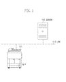
- Fig. 1 is an entire system view of an exemplary embodiment of the present invention.
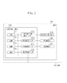
- Fig. 2 is a block diagram illustrating a configuration of an MFP according to the exemplary embodiment of the present invention.
- Fig. 3 is a block diagram illustrating a configuration of a server according to the exemplary embodiment of the present invention.
- Fig. 4 illustrates a destination information management table according to the exemplary embodiment of the present invention.
- Fig. 5 is a flowchart illustrating an operation of the MFP according to the exemplary embodiment of the present invention.
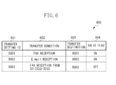
- Fig. 6 illustrates a transfer setting management table according to the exemplary embodiment of the present invention.
- Fig. 7 is a flowchart illustrating an operation of the MFP according to the exemplary embodiment of the present invention.
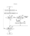
- Fig. 8 is a flowchart illustrating an operation of the MFP according to the exemplary embodiment of the present invention.
- Fig. 9 is a flowchart illustrating the operation of the MFP according to the exemplary embodiment of the present invention.
- Fig. 1 is an overview of a system of the present exemplary embodiment.
- An MFP 101 as an image processing apparatus and a server 102 as an external apparatus are connected to a local area network (LAN) 110 such that they can communicate with each other.
- the server 102 stores a destination information management table 400 which will be described in detail below and the MFP 101 can acquire the destination information via access to the destination information management table 400 in the server 102.
- FIG. 2 is a block diagram illustrating the configuration of the MFP 101.
- a control unit 210 includes a central processing unit (CPU) 211 and controls the operation of the MFP 101.
- the CPU 211 reads a control program stored in a read-only memory (ROM) 212 and executes various types of control, such as reading control and transmission control.
- ROM read-only memory
- the MFP 101 can provide various services such as copying, scanning (transmission), and printing.
- a random access memory (RAM) 213 is used as a temporary storage area such as a main memory and a work area of the CPU 211.
- a hard disk drive (HDD) 214 stores image data and various programs, a transfer setting management table 600, which will be described below, and another table (internal address book) similar to the destination information management table 400, which will be described below.
- An operation unit interface (I/F) 215 connects an operation unit 219 to the control unit 210.
- the operation unit 219 includes a liquid crystal display unit having a touch-panel function and a keyboard.
- a printer I/F 216 connects a printer 220 to the control unit 210.
- Image data to be printed by the printer 220 is transferred from the control unit 210 via the printer I/F 216 and printed on a recording medium by the printer 220.
- a scanner I/F 217 connects a scanner 221 to the control unit 210.
- the scanner 221 reads an image on a document to generate image data and inputs the image data into the control unit 210 via the scanner I/F 217.
- a network I/F 218 connects the control unit 210 (MFP 101) to the LAN 110.
- the network I/F 218 transmits image data and information to an external apparatus (e.g., the server 102) on the LAN 110 and receives various pieces information from the external apparatus on the LAN 110.
- the MFP 101 can transmit an E-mail to a mail server (not shown) on the LAN 110 from the network I/F 218.
- the MFP 101 can be equipped with a facsimile function via a modem (not shown), which is optionally available. When the facsimile function is added, the MFP 101 can execute facsimile transmission via a public line network to transmit and receive image data to/from other facsimile devices.
- FIG. 3 is a block diagram illustrating the configuration of the server 102.
- a control unit 310 includes a CPU 311 and controls the operation of the server 102.
- the CPU 311 reads a control program stored in a ROM 312 and executes various types of control processing.
- a RAM 313 is used as a temporary storage area such as a work area for a main memory and a work area of the CPU 311.
- An HDD 314 stores image data, various programs and the destination information management table (external address book) 400, which will be described below.
- a network I/F 315 connects the control unit 310 (server 102) to the LAN 110.
- the network I/F 315 transmits and receives various pieces of information from/to other apparatuses via the LAN 110.
- Fig. 4 illustrates the destination information management table (external address book) 400 stored by the HDD 314 in the server 102.
- a destination information management table (internal address book) configured in the similar manner to the destination information management table 400 is stored in the HDD 214 of the MFP 101.
- a destination ID 401 is an ID which uniquely identifies destination information managed in the destination information management table 400.
- a transmission protocol 402 indicates a transmission protocol corresponding to each destination information.
- Destination information 403 is information indicating a destination.
- a FAX is specified as the transmission protocol 402
- a telephone number is stored in the destination information 403.
- E-mail is specified as the transmission protocol 402
- an E-mail address is stored in the destination information 403.
- the destination ID 401 is set up to uniquely identify only the destination information managed in the destination information management table 400 in the server 102, it may further be set up to uniquely identify the destination information on the entire LAN 110 by being combined with a name of the server 102 or an internet protocol (IP) address of the server 102.
- IP internet protocol
- An apparatus (including the MFP 101) located on the LAN 110 can refer to the destination information management table 400 using a general-purpose protocol such as a lightweight directory access protocol (LDAP) or vendor-specified protocol.
- LDAP lightweight directory access protocol
- vendor-specified protocol vendor-specified protocol
- Fig. 5 is a flowchart illustrating a series of operations for registering a transfer setting according to an instruction from a user in the MFP 101. Each operation (step) illustrated in the flowchart in Fig. 5 is achieved when the CPU 211 of the MFP 101 executes a control program stored in the HDD 214.
- step S501 the CPU displays a transfer setting registration screen on the operation unit 219 according to the instruction of the user.
- the user inputs a transfer condition for determining whether received image data is transferred and selects a transfer destination for the image data via the transfer setting registration screen. If the transfer setting is registered via the transfer setting registration screen, when image data satisfying the transfer condition is received, the image data is automatically transferred to the transfer destination selected in advance.
- step S502 the CPU 211 determines whether the user instructs reference to an address book. If reference to the address book is instructed (YES in step S502), the procedure proceeds to step S503 and otherwise (NO in step S502), the procedure proceeds to step S507.
- the transfer setting registration screen allows an input of the transfer condition as well as selection of the transfer destination. Only the selection of the transfer destination will be described in detail here.
- step S503 the CPU 211 determines whether the address book to be referred to is an internal address book or an external address book.
- the transfer destination to be set as the transfer setting needs to be specified by referring to the address book, and directly specifying the destination information without referring to the address book is prohibited.
- step S503 if the address book referred to is the internal address book (INTERNAL in step S503), the procedure proceeds to step S504.
- step S504 the destination information management table stored in the HDD 214 of MFP 101 is referred to and then registered destination information is displayed as a list.
- the address book referred to is the external address book (EXTERNAL in step S503)
- step S505 the destination information management table stored in the HDD 314 of the server 102 is referred to and then registered destination information is displayed as a list.
- step S506 the destination ID is acquired (401 in Fig. 4 ) corresponding to the destination information selected from the destination information listed in step S504 or S505 by the user.
- step S507 the CPU 211 determines whether a registration button on the transfer setting registration screen is pressed. As a result of the determination, if it is determined that the registration button is pressed (YES in step S507), the procedure proceeds to step S508. In step S508, a content input via the transfer setting registration screen is registered on the transfer setting management table 600, which will be described below, as a transfer setting. If it is determined that the registration button is not pressed (NO in step S507), the procedure returns to step S502.
- Fig. 6 illustrates the transfer setting management table 600 stored in the HDD 214 of the MFP 101.
- a transfer setting ID 601 is an ID which uniquely identifies the transfer setting managed in the transfer setting management table 600.
- a transfer condition 602 indicates a condition for determining whether received image data is transferred. For example, in the case of the transfer setting ID 601 of "0003", when a facsimile of image data is received from a transmission source at a telephone number 03-3333-3333, the received image data is set to be automatically transferred.
- a transfer destination 603 indicates a transfer destination of the image data. As illustrated in the drawing, the transfer destination 603 stores not the destination information such as a telephone number or an E-mail address as it is, but the destination ID (401 in Fig. 4 ) assigned to identify the destination information in the address book. When the image data is actually transferred, the destination information corresponding to the destination ID is acquired from the address book using the destination ID stored in the transfer destination 603.
- a valid flag 604 indicates whether each transfer setting managed in the transfer setting management table 600 is valid or invalid.
- the valid flag 604 is ON, the transfer setting is valid, so that transfer of the image data is executed.
- the valid flag 604 is OFF, the transfer setting is invalid and even if the image data satisfying the transfer condition is received, transfer of the image data is not executed. The user can change manually whether each transfer setting is valid or not, as required.
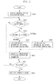
- Fig. 7 is a flowchart illustrating a series of operations when the MFP 101 receives the image data. Each operation (step) illustrated in the flowchart in Fig. 7 is achieved when the CPU 211 of the MFP 101 executes a control program stored in the HDD 214.
- step S701 the MFP 101 receives image data.
- the MFP 101 may use any one of E-mail and facsimile transmission. If the image data is received in step S701, the procedure proceeds to step S702, in which the CPU 211 accesses the transfer setting management table 600 to refer to the registered transfer settings.
- step S703 the CPU 211 determines whether there exists any transfer setting for which the valid flag 604 is ON and the image data received in step S701 satisfies the transfer condition 602. As a result of the determination, if there is any transfer setting corresponding to the above described condition (YES in step S703), the procedure proceeds to step S704 and otherwise (NO in step S703), the procedure proceeds to step S711.
- step S704 the CPU 211 acquires the destination information corresponding to the destination ID using the destination ID contained in the transfer setting. If the corresponding destination information is managed in the destination information management table 400 in the server 102, the MFP 101 acquires the destination information by communicating with the server 102 via the LAN 110.
- step S705 the CPU 211 determines whether acquisition of the destination information in step S704 is successful. If it is determined that the acquisition of the destination information is successful (YES in step S705), the procedure proceeds to step S706. If the acquisition of the destination information fails (NO in step S705), the procedure proceeds to step S708.
- step S705 may be omitted. This is appropriate in embodiments where the MFP 101 is adapted to, when the destination information is deleted from the destination information management table stored in the HDD 214, automatically invalidate the transfer setting (valid flag 604 turned off) including the destination ID corresponding to the deleted destination information.
- step S704 the procedure proceeds to step S706 while omitting step S705.
- step S706 the image data received in step S701 is transferred using the destination information acquired in step S704.
- step S707 the CPU 211 determines whether the transfer in step S706 is successful. If it is determined that the transfer is successful (YES in step S707), the processing is terminated. If the transfer fails (NO in step S707), the procedure proceeds to step S710.
- step S708 the CPU 211 determines the cause for the failure of the acquisition of the destination information in step S704. If the destination information corresponding to the destination ID contained in the transfer setting is stored in the HDD 314 of the server 102, the acquisition of the destination information may fail due to occurrence of a network failure on the LAN 110 or a busy status of the server 102.
- step S708 if a response from the server 102 to a destination information acquisition request from the MFP 101 indicates that no relevant destination information exists (NO DESTINATION INFORMATION in step S708), the procedure advances to step S709.
- a case where no relevant destination information exists is, for example, considered to be a case where the destination information is deleted from the destination information management table 400 in the server 102 after the transfer setting is registered. If the destination information is deleted in the server 102, the MFP 101 cannot know immediately that the destination information is deleted, different from the case where the destination information is deleted in the MFP 101.
- step S709 the valid flag 604 for the transfer setting is turned OFF. Consequently, this can prevent execution of waste processing of, with the transfer setting left in the valid state although the destination information does not exist, attempting to acquire the destination information each time when image data satisfying the transfer condition is received.
- step S709 processing of invalidating the transfer setting in step S709 is not executed.
- step S710 the operation unit 219 displays a message which notifies the user that the transfer of image data fails.
- the image data received in step S701 is stored in a preliminarily specified storage area in the HDD 214.
- the image data may be printed by the printer 220 instead of being stored into the HDD 214.
- the transfer setting is maintained in a valid state without being invalidated.
- the transfer setting is invalidated.
- Fig. 8 is a flowchart illustrating a series of operations executed before image data is received (irrespective of whether the image data is received) in the MFP 101. Each operation (step) illustrated in the flowchart in Fig. 8 is achieved when the CPU 211 of the MFP 101 executes a control program stored in the HDD 214.
- the processing illustrated in the flowchart in Fig. 8 may be started periodically (every specified time) or when a list of registered transfer settings is displayed or a specific transfer setting is displayed in detail.
- step S801 the CPU 211 picks up a transfer setting from the transfer setting management table 600. Only a transfer setting for which the valid flag 604 is ON is taken as a target object and the transfer setting whose valid flag 604 is OFF is not treated as a target object.
- step S802 by using the destination ID contained in the transfer setting picked up in step S801, destination information corresponding to the relevant destination ID is acquired. If the corresponding destination information is managed in the destination information management table 400, the MFP 101 acquires the destination information by communicating with the server 102 via the LAN 110.
- step S803 the CPU 211 determines whether the acquisition of the destination information in step S802 is successful. If the acquisition of the destination information is successful (YES in step S803), the acquired destination information is discarded and then the procedure proceeds to step S806. If the acquisition of the destination information fails (NO in step S803), the procedure proceeds to step S804.
- the processing in steps S802 and S803 may be omitted. This is appropriate in embodiments where the MFP 101 is adapted to, when the destination information is deleted from the destination information management table stored in the HDD 214, automatically invalidate the transfer setting including the destination ID corresponding to the deleted destination information.
- step S801 the procedure proceeds to step S806 while omitting steps S802 and 803.
- step S804 the CPU 211 determines the cause for the failure of the acquisition of the destination information in step S801. If the destination information corresponding to the destination ID contained in the transfer setting is stored in the HDD 314 of the server 102, the acquisition of the destination information may fail due to occurrence of a network failure on the LAN 110 or a busy status of the server 102.
- step S804 if a response from the server 102 to a destination information acquisition request from the MFP 101 indicates that no relevant destination information exists (NO DESTINATION INFORMATION in step S804), the procedure proceeds to step S805.
- a case where no relevant destination information exists is, for example, considered to be a case where the destination information is deleted from the destination information management table 400 in the server 102 after the transfer setting is registered. If the destination information is deleted in the server 102, the MFP 101 cannot know immediately that the destination information is deleted, different from the case where the destination information is deleted in the MFP 101.
- step S805 the valid flag 604 for the transfer setting is turned OFF. Consequently, this can prevent execution of waste processing of, with the transfer setting left in the valid state although the destination information does not exist, attempting to acquire the destination information each time when image data satisfying the transfer condition is received.
- step S804 if no response is received from the server 102 to the destination information acquisition request from the MFP 101 or a server-busy response is received, the failure of the acquisition of the destination is considered to originate from a communication error with the server 102 (TRANSMISSION ERROR in step S804), and then, the procedure proceeds to step S806. In this case, processing of invalidating the transfer setting in step S805 is not executed.
- step S806 the CPU 211 determines whether any unprocessed transfer setting exists in transfer settings managed in the transfer setting management table 600 while the valid flag 604 is ON. As a result of the determination, if any unprocessed transfer setting exits (YES in step S806), the procedure returns to step S801, and the CPU 211 picks up a next transfer setting. On the other hand, if there exists no unprocessed transfer setting (NO in step S806), the procedure is terminated.
- determination of whether the destination information can be acquired is executed prior to receiving the image data (irrespective of receiving of the image data) so that, when the image data is received, the possibility that the acquisition of the destination information may fail can be reduced. If the acquisition of the destination information fails, whether the transfer setting will be invalidated or not can be changed according to the cause for the failure of the acquisition.
- the flowcharts illustrated in Figs. 7 and 8 describe an example in which as long as the cause for the failure of the acquisition of the destination information is a communication error, the transfer setting is not invalidated. In this respect, a following configuration is available. If the communication error continues beyond a predetermined number of times or a predetermined period, it can be determined that a state disabling the acquisition of the destination information is not temporary, and the transfer setting may be invalidated (turn OFF the valid flag 604).
- step S709 in Fig. 7 or step S805 in Fig. 8 the destination ID stored in the transfer destination 603 of the transfer setting management table 600 is deleted. After that, when the user selects a new transfer destination (i.e., a new destination ID is set), he or she can change the valid flag 604 from OFF to ON to reregister the transfer destination as a valid transfer setting.
- a new transfer destination i.e., a new destination ID is set
- Fig. 9 is a flowchart illustrating a series of operations to be executed when the MFP 101 changes the valid flag 604 for a transfer setting from OFF to ON (changes the transfer setting from an invalid status to a valid status).
- Each operation (step) illustrated in the flowchart in Fig. 9 is achieved when the CPU 211 of the MFP 101 executes a control program stored in the HDD 214.
- the processing illustrated in the flowchart in Fig. 9 is started when a user selects a transfer setting for which the valid flag 604 is OFF and instructs the MFP 101 to turn ON the valid flag.
- step S901 the CPU 211 acquires destination information corresponding to a relevant destination ID using the destination ID contained in the transfer setting. If the corresponding destination information is managed in the destination information management table 400, the MFP 101 acquires the destination information by communicating with the server 102 via the LAN 110.
- step S902 the CPU 211 determines whether the acquisition of the destination information in step S901 is successful. As a result of the determination, if the acquisition of the destination information is successful (YES in step S902), the procedure proceeds to step S903. If the acquisition of the destination information fails (NO in step S902), the procedure proceeds to step S904.
- the HDD 214 of the MFP 101 stores the destination information corresponding to the destination ID contained in the transfer setting, it is permissible to refrain from starting the flowchart in Fig. 9 . This is appropriate in embodiments where the MFP 101 is adapted to, when the destination information is deleted from the destination information management table stored in the HDD 214, automatically invalidate the transfer setting including the destination ID corresponding to the deleted destination information.
- step S903 the CPU 211 changes the valid flag 604 of the transfer setting selected by user ON. Consequently, the transfer setting is changed to the valid status.
- step S904 a message for notifying user that the acquisition of the destination information fails is displayed on the operation unit 219.
- the reason is that if the transfer setting is turned to the valid status although the acquisition of the destination information is unsuccessful, when image data is transferred, the acquisition of the destination information may be unsuccessful and causes an error. If the acquisition of the destination information in step S901 fails, the CPU 211 prompts the user to confirm the failure without turning ON the valid flag 604 for the transfer setting.
- step S904 is executed irrespective of the cause for the failure of the acquisition of the destination information.
- aspects of the present invention can also be realized by a computer of a system or apparatus (or devices such as a CPU or a micro processing unit (MPU) ) that reads out and executes a program recorded on a memory device to perform the functions of the above-described embodiment (s), and by a method, the steps of which are performed by a computer of a system or apparatus by, for example, reading out and executing a program recorded on a memory device to perform the functions of the above-described embodiment(s).
- the program is provided to the computer for example via a network or from a recording medium of various types serving as the memory device (e.g., computer-readable medium).
Landscapes
- Engineering & Computer Science (AREA)
- Signal Processing (AREA)
- Multimedia (AREA)
- Computer Networks & Wireless Communication (AREA)
- Automation & Control Theory (AREA)
- General Engineering & Computer Science (AREA)
- Computing Systems (AREA)
- Facsimiles In General (AREA)
- Facsimile Transmission Control (AREA)
Abstract
Description
- The present invention relates to an image processing apparatus capable of communicating with an external apparatus via a network to acquire destination information from the external apparatus.
- Conventionally, an image processing apparatus such as a multi-function peripheral can transfer received image data to another apparatus. To automatically transfer the received image data, it is necessary to previously register a transfer setting including a transfer condition for determining whether the received image data is to be transferred, and destination information indicating a transfer destination. Registering the transfer setting enables the image data to be automatically transferred using the destination information contained in the transfer setting when the image processing apparatus receives the image data satisfying the transfer condition.
- Various types of transmission protocols such as facsimile (FAX), E-mail, a file transfer protocol (FTP), and server message block (SMB) are available to transfer image data. The transfer destination of the image data is specified using the destination information corresponding to each transmission protocol. For example, when the image data is transferred using a facsimile, a telephone number is used as the destination information and when the image data is transferred via E-mail, an E-mail address is used as the destination information.
- Instead of directly registering the destination information such as a telephone number and an E-mail address in the transfer setting, a method for registering an identification (ID) corresponding to destination information registered in an address book as the transfer setting has been proposed. In this case, when an image processing apparatus receives image data satisfying a transfer condition, it acquires destination information corresponding to the ID contained in the transfer setting from the address book and then transfers the image data.
- Japanese Patent Application Laid-Open No.
2002-077472 - Recently, instead of referring to the address book in the image processing apparatus, the image processing apparatus can refer to an address book in an external apparatus which can communicate with via a network and acquire destination information from the external apparatus, as discussed in Japanese Patent Application Laid-Open No.
2002-077472 - However, if a configuration for acquiring the destination information from the external apparatus is adopted, there is a possibility that an operator cannot immediately know that the destination information stored in the external apparatus has been deleted and thus the destination information is left in a state in which its transfer setting is valid even after the destination information has been deleted. Additionally, if the image processing apparatus is configured to equally invalidate all the transfer settings when the image processing apparatus cannot acquire the destination information, all the transfer settings might be invalidated, even if the destination information cannot be acquired due to a temporary communication error, such as a network failure and server busy status, and acquisition of the destination information is restored after a time passes.
- The present invention relates to a mechanism whereby, if no destination information can be acquired, whether or not a transfer setting is invalidated is determined according to the reason why the destination information cannot be acquired.
- According to a first aspect of the present invention, there is provided an image processing apparatus as specified in
claim 1. According to a second aspect of the present invention, there is provided a method as specified in claim 6. According to a third aspect of the present invention, there is provided a program as specified in claim 8. The invention extends to methods, apparatus and/or use substantially as herein described with reference to the accompanying drawings. Any feature in one aspect of the invention may be applied to other aspects of the invention, in any appropriate combination. In particular, features of method aspects may be applied to apparatus aspects, and vice versa. Furthermore, features implemented in hardware may generally be implemented in software, and vice versa. Any reference to software and hardware features herein should be construed accordingly. - Further features and aspects of the present invention will now be described by way of example with reference to the attached drawings.
- The accompanying drawings, which are incorporated in and constitute a part of the specification, illustrate embodiments, features, and aspects of the invention and, together with the description, serve to explain the principles of the invention.
-
Fig. 1 is an entire system view of an exemplary embodiment of the present invention. -
Fig. 2 is a block diagram illustrating a configuration of an MFP according to the exemplary embodiment of the present invention. -
Fig. 3 is a block diagram illustrating a configuration of a server according to the exemplary embodiment of the present invention. -
Fig. 4 illustrates a destination information management table according to the exemplary embodiment of the present invention. -
Fig. 5 is a flowchart illustrating an operation of the MFP according to the exemplary embodiment of the present invention. -
Fig. 6 illustrates a transfer setting management table according to the exemplary embodiment of the present invention. -
Fig. 7 is a flowchart illustrating an operation of the MFP according to the exemplary embodiment of the present invention. -
Fig. 8 is a flowchart illustrating an operation of the MFP according to the exemplary embodiment of the present invention. -
Fig. 9 is a flowchart illustrating the operation of the MFP according to the exemplary embodiment of the present invention. - Various exemplary embodiments, features, and aspects of the invention will be described in detail below with reference to the drawings.
- Note that not all combinations of features described in the exemplary embodiments below are necessary for providing a solution according to the present invention.
-
Fig. 1 is an overview of a system of the present exemplary embodiment. An MFP 101 as an image processing apparatus and aserver 102 as an external apparatus are connected to a local area network (LAN) 110 such that they can communicate with each other. Theserver 102 stores a destination information management table 400 which will be described in detail below and the MFP 101 can acquire the destination information via access to the destination information management table 400 in theserver 102. -
Fig. 2 is a block diagram illustrating the configuration of theMFP 101. Acontrol unit 210 includes a central processing unit (CPU) 211 and controls the operation of theMFP 101. TheCPU 211 reads a control program stored in a read-only memory (ROM) 212 and executes various types of control, such as reading control and transmission control. Thus, the MFP 101 can provide various services such as copying, scanning (transmission), and printing. A random access memory (RAM) 213 is used as a temporary storage area such as a main memory and a work area of theCPU 211. - A hard disk drive (HDD) 214 stores image data and various programs, a transfer setting management table 600, which will be described below, and another table (internal address book) similar to the destination information management table 400, which will be described below. An operation unit interface (I/F) 215 connects an
operation unit 219 to thecontrol unit 210. Theoperation unit 219 includes a liquid crystal display unit having a touch-panel function and a keyboard. - A printer I/F 216 connects a
printer 220 to thecontrol unit 210. Image data to be printed by theprinter 220 is transferred from thecontrol unit 210 via the printer I/F 216 and printed on a recording medium by theprinter 220. - A scanner I/F 217 connects a
scanner 221 to thecontrol unit 210. Thescanner 221 reads an image on a document to generate image data and inputs the image data into thecontrol unit 210 via the scanner I/F 217. - A network I/F 218 connects the control unit 210 (MFP 101) to the
LAN 110. The network I/F 218 transmits image data and information to an external apparatus (e.g., the server 102) on theLAN 110 and receives various pieces information from the external apparatus on theLAN 110. The MFP 101 can transmit an E-mail to a mail server (not shown) on theLAN 110 from the network I/F 218. - The MFP 101 can be equipped with a facsimile function via a modem (not shown), which is optionally available. When the facsimile function is added, the MFP 101 can execute facsimile transmission via a public line network to transmit and receive image data to/from other facsimile devices.
-
Fig. 3 is a block diagram illustrating the configuration of theserver 102. Acontrol unit 310 includes aCPU 311 and controls the operation of theserver 102. TheCPU 311 reads a control program stored in aROM 312 and executes various types of control processing. ARAM 313 is used as a temporary storage area such as a work area for a main memory and a work area of theCPU 311. AnHDD 314 stores image data, various programs and the destination information management table (external address book) 400, which will be described below. - A network I/
F 315 connects the control unit 310 (server 102) to theLAN 110. The network I/F 315 transmits and receives various pieces of information from/to other apparatuses via theLAN 110. -
Fig. 4 illustrates the destination information management table (external address book) 400 stored by theHDD 314 in theserver 102. A destination information management table (internal address book) configured in the similar manner to the destination information management table 400 is stored in theHDD 214 of theMFP 101. - A
destination ID 401 is an ID which uniquely identifies destination information managed in the destination information management table 400. Atransmission protocol 402 indicates a transmission protocol corresponding to each destination information.Destination information 403 is information indicating a destination. When a FAX is specified as thetransmission protocol 402, a telephone number is stored in thedestination information 403. For example, when E-mail is specified as thetransmission protocol 402, an E-mail address is stored in thedestination information 403. - Although in some embodiments the
destination ID 401 is set up to uniquely identify only the destination information managed in the destination information management table 400 in theserver 102, it may further be set up to uniquely identify the destination information on theentire LAN 110 by being combined with a name of theserver 102 or an internet protocol (IP) address of theserver 102. - An apparatus (including the MFP 101) located on the
LAN 110 can refer to the destination information management table 400 using a general-purpose protocol such as a lightweight directory access protocol (LDAP) or vendor-specified protocol. -
Fig. 5 is a flowchart illustrating a series of operations for registering a transfer setting according to an instruction from a user in theMFP 101. Each operation (step) illustrated in the flowchart inFig. 5 is achieved when theCPU 211 of theMFP 101 executes a control program stored in theHDD 214. - In step S501, the CPU displays a transfer setting registration screen on the
operation unit 219 according to the instruction of the user. The user inputs a transfer condition for determining whether received image data is transferred and selects a transfer destination for the image data via the transfer setting registration screen. If the transfer setting is registered via the transfer setting registration screen, when image data satisfying the transfer condition is received, the image data is automatically transferred to the transfer destination selected in advance. - In step S502, the
CPU 211 determines whether the user instructs reference to an address book. If reference to the address book is instructed (YES in step S502), the procedure proceeds to step S503 and otherwise (NO in step S502), the procedure proceeds to step S507. As described above, the transfer setting registration screen allows an input of the transfer condition as well as selection of the transfer destination. Only the selection of the transfer destination will be described in detail here. - In step S503, the
CPU 211 determines whether the address book to be referred to is an internal address book or an external address book. In the present example, the transfer destination to be set as the transfer setting needs to be specified by referring to the address book, and directly specifying the destination information without referring to the address book is prohibited. - As a result of determination in step S503, if the address book referred to is the internal address book (INTERNAL in step S503), the procedure proceeds to step S504. In step S504, the destination information management table stored in the
HDD 214 ofMFP 101 is referred to and then registered destination information is displayed as a list. On the other hand, if the address book referred to is the external address book (EXTERNAL in step S503), the procedure proceeds to step S505. In step S505, the destination information management table stored in theHDD 314 of theserver 102 is referred to and then registered destination information is displayed as a list. - In step S506, the destination ID is acquired (401 in
Fig. 4 ) corresponding to the destination information selected from the destination information listed in step S504 or S505 by the user. - In step S507, the
CPU 211 determines whether a registration button on the transfer setting registration screen is pressed. As a result of the determination, if it is determined that the registration button is pressed (YES in step S507), the procedure proceeds to step S508. In step S508, a content input via the transfer setting registration screen is registered on the transfer setting management table 600, which will be described below, as a transfer setting. If it is determined that the registration button is not pressed (NO in step S507), the procedure returns to step S502. -
Fig. 6 illustrates the transfer setting management table 600 stored in theHDD 214 of theMFP 101. Atransfer setting ID 601 is an ID which uniquely identifies the transfer setting managed in the transfer setting management table 600. - A
transfer condition 602 indicates a condition for determining whether received image data is transferred. For example, in the case of thetransfer setting ID 601 of "0003", when a facsimile of image data is received from a transmission source at a telephone number 03-3333-3333, the received image data is set to be automatically transferred. - A
transfer destination 603 indicates a transfer destination of the image data. As illustrated in the drawing, thetransfer destination 603 stores not the destination information such as a telephone number or an E-mail address as it is, but the destination ID (401 inFig. 4 ) assigned to identify the destination information in the address book. When the image data is actually transferred, the destination information corresponding to the destination ID is acquired from the address book using the destination ID stored in thetransfer destination 603. - A
valid flag 604 indicates whether each transfer setting managed in the transfer setting management table 600 is valid or invalid. When thevalid flag 604 is ON, the transfer setting is valid, so that transfer of the image data is executed. On the other hand, when thevalid flag 604 is OFF, the transfer setting is invalid and even if the image data satisfying the transfer condition is received, transfer of the image data is not executed. The user can change manually whether each transfer setting is valid or not, as required. -
Fig. 7 is a flowchart illustrating a series of operations when theMFP 101 receives the image data. Each operation (step) illustrated in the flowchart inFig. 7 is achieved when theCPU 211 of theMFP 101 executes a control program stored in theHDD 214. - In step S701, the
MFP 101 receives image data. When receiving the image data, theMFP 101 may use any one of E-mail and facsimile transmission. If the image data is received in step S701, the procedure proceeds to step S702, in which theCPU 211 accesses the transfer setting management table 600 to refer to the registered transfer settings. - In step S703, the
CPU 211 determines whether there exists any transfer setting for which thevalid flag 604 is ON and the image data received in step S701 satisfies thetransfer condition 602. As a result of the determination, if there is any transfer setting corresponding to the above described condition (YES in step S703), the procedure proceeds to step S704 and otherwise (NO in step S703), the procedure proceeds to step S711. - In step S704, the
CPU 211 acquires the destination information corresponding to the destination ID using the destination ID contained in the transfer setting. If the corresponding destination information is managed in the destination information management table 400 in theserver 102, theMFP 101 acquires the destination information by communicating with theserver 102 via theLAN 110. - In step S705, the
CPU 211 determines whether acquisition of the destination information in step S704 is successful. If it is determined that the acquisition of the destination information is successful (YES in step S705), the procedure proceeds to step S706. If the acquisition of the destination information fails (NO in step S705), the procedure proceeds to step S708. - If the destination information corresponding to the destination ID contained in the transfer setting is stored in the
HDD 214 of theMFP 101, processing in step S705 may be omitted. This is appropriate in embodiments where theMFP 101 is adapted to, when the destination information is deleted from the destination information management table stored in theHDD 214, automatically invalidate the transfer setting (valid flag 604 turned off) including the destination ID corresponding to the deleted destination information. - Due to this function, if the
HDD 214 in theMFP 101 stores the destination information corresponding to the destination ID contained in the transfer setting, the acquisition of the destination information never fails. Therefore, after step S704, the procedure proceeds to step S706 while omitting step S705. - In step S706, the image data received in step S701 is transferred using the destination information acquired in step S704.
- In step S707, the
CPU 211 determines whether the transfer in step S706 is successful. If it is determined that the transfer is successful (YES in step S707), the processing is terminated. If the transfer fails (NO in step S707), the procedure proceeds to step S710. - In step S708, the
CPU 211 determines the cause for the failure of the acquisition of the destination information in step S704. If the destination information corresponding to the destination ID contained in the transfer setting is stored in theHDD 314 of theserver 102, the acquisition of the destination information may fail due to occurrence of a network failure on theLAN 110 or a busy status of theserver 102. - In step S708, if a response from the
server 102 to a destination information acquisition request from theMFP 101 indicates that no relevant destination information exists (NO DESTINATION INFORMATION in step S708), the procedure advances to step S709. A case where no relevant destination information exists is, for example, considered to be a case where the destination information is deleted from the destination information management table 400 in theserver 102 after the transfer setting is registered. If the destination information is deleted in theserver 102, theMFP 101 cannot know immediately that the destination information is deleted, different from the case where the destination information is deleted in theMFP 101. - In step S709, the
valid flag 604 for the transfer setting is turned OFF. Consequently, this can prevent execution of waste processing of, with the transfer setting left in the valid state although the destination information does not exist, attempting to acquire the destination information each time when image data satisfying the transfer condition is received. - On the other hand, if no response is received from the
server 102 to the destination information acquisition request from theMFP 101 or a server-busy response is received, the failure of the acquisition of the destination is considered to originate from a communication error with the server 102 (TRANSMISSION ERROR in step S708), and then, the procedure proceeds to step S710. In this case, processing of invalidating the transfer setting in step S709 is not executed. - In step S710, the
operation unit 219 displays a message which notifies the user that the transfer of image data fails. In step S711, the image data received in step S701 is stored in a preliminarily specified storage area in theHDD 214. In step S711, the image data may be printed by theprinter 220 instead of being stored into theHDD 214. - According to the above-described processing, if the acquisition of the destination information from the
server 102 fails, whether or not the transfer setting is invalidated is determined according to the cause for the failure of the acquisition. More specifically, if the acquisition of the destination information is temporarily disabled due to a communication error, it is expected that the acquisition of the destination information will be restored after a time passes. Thus, the transfer setting is maintained in a valid state without being invalidated. - On the other hand, if the acquisition of the destination information fails due to inexistence of the destination information (not being stored) in the
server 102, it cannot be expected that the acquisition of the destination information will be restored even after a time passes. Thus, the transfer setting is invalidated. -
Fig. 8 is a flowchart illustrating a series of operations executed before image data is received (irrespective of whether the image data is received) in theMFP 101. Each operation (step) illustrated in the flowchart inFig. 8 is achieved when theCPU 211 of theMFP 101 executes a control program stored in theHDD 214. - The processing illustrated in the flowchart in
Fig. 8 may be started periodically (every specified time) or when a list of registered transfer settings is displayed or a specific transfer setting is displayed in detail. - In step S801, the
CPU 211 picks up a transfer setting from the transfer setting management table 600. Only a transfer setting for which thevalid flag 604 is ON is taken as a target object and the transfer setting whosevalid flag 604 is OFF is not treated as a target object. - In step S802, by using the destination ID contained in the transfer setting picked up in step S801, destination information corresponding to the relevant destination ID is acquired. If the corresponding destination information is managed in the destination information management table 400, the
MFP 101 acquires the destination information by communicating with theserver 102 via theLAN 110. - In step S803, the
CPU 211 determines whether the acquisition of the destination information in step S802 is successful. If the acquisition of the destination information is successful (YES in step S803), the acquired destination information is discarded and then the procedure proceeds to step S806. If the acquisition of the destination information fails (NO in step S803), the procedure proceeds to step S804. - If the destination information corresponding to the destination ID contained in the transfer setting is stored in the
HDD 214 of theMFP 101, the processing in steps S802 and S803 may be omitted. This is appropriate in embodiments where theMFP 101 is adapted to, when the destination information is deleted from the destination information management table stored in theHDD 214, automatically invalidate the transfer setting including the destination ID corresponding to the deleted destination information. - Due to this function, if the
HDD 214 in theMFP 101 stores the destination information corresponding to the destination ID contained in the transfer setting, the acquisition of the destination information never fails. Therefore, after step S801, the procedure proceeds to step S806 while omitting steps S802 and 803. - In step S804, the
CPU 211 determines the cause for the failure of the acquisition of the destination information in step S801. If the destination information corresponding to the destination ID contained in the transfer setting is stored in theHDD 314 of theserver 102, the acquisition of the destination information may fail due to occurrence of a network failure on theLAN 110 or a busy status of theserver 102. - In step S804, if a response from the
server 102 to a destination information acquisition request from theMFP 101 indicates that no relevant destination information exists (NO DESTINATION INFORMATION in step S804), the procedure proceeds to step S805. A case where no relevant destination information exists is, for example, considered to be a case where the destination information is deleted from the destination information management table 400 in theserver 102 after the transfer setting is registered. If the destination information is deleted in theserver 102, theMFP 101 cannot know immediately that the destination information is deleted, different from the case where the destination information is deleted in theMFP 101. - In step S805, the
valid flag 604 for the transfer setting is turned OFF. Consequently, this can prevent execution of waste processing of, with the transfer setting left in the valid state although the destination information does not exist, attempting to acquire the destination information each time when image data satisfying the transfer condition is received. - On the other hand, if no response is received from the
server 102 to the destination information acquisition request from theMFP 101 or a server-busy response is received, the failure of the acquisition of the destination is considered to originate from a communication error with the server 102 (TRANSMISSION ERROR in step S804), and then, the procedure proceeds to step S806. In this case, processing of invalidating the transfer setting in step S805 is not executed. - In step S806, the
CPU 211 determines whether any unprocessed transfer setting exists in transfer settings managed in the transfer setting management table 600 while thevalid flag 604 is ON. As a result of the determination, if any unprocessed transfer setting exits (YES in step S806), the procedure returns to step S801, and theCPU 211 picks up a next transfer setting. On the other hand, if there exists no unprocessed transfer setting (NO in step S806), the procedure is terminated. - According to the above-described processing, determination of whether the destination information can be acquired is executed prior to receiving the image data (irrespective of receiving of the image data) so that, when the image data is received, the possibility that the acquisition of the destination information may fail can be reduced. If the acquisition of the destination information fails, whether the transfer setting will be invalidated or not can be changed according to the cause for the failure of the acquisition.
- The flowcharts illustrated in
Figs. 7 and8 describe an example in which as long as the cause for the failure of the acquisition of the destination information is a communication error, the transfer setting is not invalidated. In this respect, a following configuration is available. If the communication error continues beyond a predetermined number of times or a predetermined period, it can be determined that a state disabling the acquisition of the destination information is not temporary, and the transfer setting may be invalidated (turn OFF the valid flag 604). - When the transfer setting is invalidated in step S709 in
Fig. 7 or step S805 inFig. 8 , the destination ID stored in thetransfer destination 603 of the transfer setting management table 600 is deleted. After that, when the user selects a new transfer destination (i.e., a new destination ID is set), he or she can change thevalid flag 604 from OFF to ON to reregister the transfer destination as a valid transfer setting. -
Fig. 9 is a flowchart illustrating a series of operations to be executed when theMFP 101 changes thevalid flag 604 for a transfer setting from OFF to ON (changes the transfer setting from an invalid status to a valid status). Each operation (step) illustrated in the flowchart inFig. 9 is achieved when theCPU 211 of theMFP 101 executes a control program stored in theHDD 214. The processing illustrated in the flowchart inFig. 9 is started when a user selects a transfer setting for which thevalid flag 604 is OFF and instructs theMFP 101 to turn ON the valid flag. - In step S901, the
CPU 211 acquires destination information corresponding to a relevant destination ID using the destination ID contained in the transfer setting. If the corresponding destination information is managed in the destination information management table 400, theMFP 101 acquires the destination information by communicating with theserver 102 via theLAN 110. - In step S902, the
CPU 211 determines whether the acquisition of the destination information in step S901 is successful. As a result of the determination, if the acquisition of the destination information is successful (YES in step S902), the procedure proceeds to step S903. If the acquisition of the destination information fails (NO in step S902), the procedure proceeds to step S904. - If the
HDD 214 of theMFP 101 stores the destination information corresponding to the destination ID contained in the transfer setting, it is permissible to refrain from starting the flowchart inFig. 9 . This is appropriate in embodiments where theMFP 101 is adapted to, when the destination information is deleted from the destination information management table stored in theHDD 214, automatically invalidate the transfer setting including the destination ID corresponding to the deleted destination information. - Due to this function, if the
HDD 214 in theMFP 101 stores the destination information corresponding to the destination ID contained in the transfer setting, the acquisition of the destination information never fails. - In step S903, the
CPU 211 changes thevalid flag 604 of the transfer setting selected by user ON. Consequently, the transfer setting is changed to the valid status. - In step S904, a message for notifying user that the acquisition of the destination information fails is displayed on the
operation unit 219. The reason is that if the transfer setting is turned to the valid status although the acquisition of the destination information is unsuccessful, when image data is transferred, the acquisition of the destination information may be unsuccessful and causes an error. If the acquisition of the destination information in step S901 fails, theCPU 211 prompts the user to confirm the failure without turning ON thevalid flag 604 for the transfer setting. - According to the flowcharts illustrated in
Figs. 7 and8 , different processing is executed according to the cause for the failure of the acquisition of the destination information. On the other hand, according to the flowchart illustrated inFig. 9 , the same processing (step S904) is executed irrespective of the cause for the failure of the acquisition of the destination information. - The reason is that, while the user does not always operate the
MFP 101 when executing the flowcharts illustrated inFigs. 7 and8 , evidently he or she operates theMFP 101 when executing the flowchart illustrated inFig. 9 . More specifically, if the user operates theMFP 101, he or she can confirm that a specified transfer destination is mistaken when informed of a failure of the acquisition of the destination information irrespective of the cause for the failure. - Aspects of the present invention can also be realized by a computer of a system or apparatus (or devices such as a CPU or a micro processing unit (MPU) ) that reads out and executes a program recorded on a memory device to perform the functions of the above-described embodiment (s), and by a method, the steps of which are performed by a computer of a system or apparatus by, for example, reading out and executing a program recorded on a memory device to perform the functions of the above-described embodiment(s). For this purpose, the program is provided to the computer for example via a network or from a recording medium of various types serving as the memory device (e.g., computer-readable medium).
- It will be understood that the present invention has been described above purely by way of example, and modification of detail can be made within the scope of the invention. Each feature disclosed in the description, and (where appropriate) the claims and drawings may be provided independently or in any appropriate combination.
Claims (8)
- An image processing apparatus (101) capable of communicating with an external apparatus (102) via a network (110), the image processing apparatus comprising:receiving means for receiving image data;registering means for registering a transfer setting containing an ID for identifying destination information stored in the external apparatus to transfer the image data received by the receiving means;acquisition means for acquiring the destination information corresponding to the ID contained in the transfer setting registered by the registering means from the external apparatus;transfer means for transferring the image data received by the receiving means using the destination information acquired by the acquisition means;determining means for, in a case where the acquisition means cannot acquire the destination information, determining the cause of not being able to acquire the destination information; andcontrol means for refraining from invalidating the transfer setting registered by the registering means when the determined cause is due to a communication error with the external apparatus, and invalidating the transfer setting registered by the registering means when the determined cause is that no destination information corresponding to the ID is stored in the external apparatus.
- The image processing apparatus according to claim 1, wherein the acquisition means acquires the destination information from the external apparatus in response to receiving of the image data by the receiving means.
- The image processing apparatus according to claim 1, wherein the acquisition means, determining means and control means are operable independently of the receiving means, registering means and transfer means, so as to confirm whether the acquisition means is capable of acquiring destination information corresponding to a given ID prior to receiving of the image data by the receiving means.
- The image processing apparatus according to claim 1, further comprising deletion means for deleting the ID contained in the transfer setting if the control means invalidates the transfer setting.
- The image processing apparatus according to claim 1, wherein the transfer setting invalidated by the control means can be reregistered in the registering means as a valid transfer setting by specifying a new ID.
- A method for controlling an image processing apparatus (101) capable of communicating with an external apparatus (102) via a network (110), the method comprising:obtaining a registered transfer setting containing an ID for identifying destination information stored in the external apparatus to transfer image data received at the image processing apparatus;acquiring the destination information corresponding to the ID contained in the registered transfer setting from the external apparatus;in a case where the destination information cannot be acquired, determining the cause of not being able to acquire the destination information; andrefraining from invalidating the registered transfer setting when the determined cause is due to a communication error with the external apparatus, and invalidating the registered transfer setting when the determined cause is that no destination information corresponding to the ID is stored in the external apparatus.
- A method according to Claim 6, further comprising receiving image data and transferring the image data according to the acquired destination information.
- A program for causing a computer to execute a method according to claims 6 or 7.
Applications Claiming Priority (1)
| Application Number | Priority Date | Filing Date | Title |
|---|---|---|---|
| JP2010215664A JP5754906B2 (en) | 2010-09-27 | 2010-09-27 | Image processing apparatus, control method thereof, and program |
Publications (3)
| Publication Number | Publication Date |
|---|---|
| EP2434744A2 true EP2434744A2 (en) | 2012-03-28 |
| EP2434744A3 EP2434744A3 (en) | 2017-08-02 |
| EP2434744B1 EP2434744B1 (en) | 2021-12-08 |
Family
ID=44936163
Family Applications (1)
| Application Number | Title | Priority Date | Filing Date |
|---|---|---|---|
| EP11180762.4A Active EP2434744B1 (en) | 2010-09-27 | 2011-09-09 | Image processing apparatus, control method thereof, and program |
Country Status (4)
| Country | Link |
|---|---|
| US (1) | US9516191B2 (en) |
| EP (1) | EP2434744B1 (en) |
| JP (1) | JP5754906B2 (en) |
| CN (1) | CN102420924B (en) |
Families Citing this family (12)
| Publication number | Priority date | Publication date | Assignee | Title |
|---|---|---|---|---|
| JP5247540B2 (en) * | 2009-03-02 | 2013-07-24 | キヤノン株式会社 | Information processing system, control method therefor, and program |
| JP2013038630A (en) * | 2011-08-09 | 2013-02-21 | Brother Ind Ltd | Facsimile device |
| JP5888300B2 (en) * | 2013-08-30 | 2016-03-16 | コニカミノルタ株式会社 | Portable terminal device, image processing device registration method and registration program in the same device |
| JP6197683B2 (en) * | 2014-02-16 | 2017-09-20 | ブラザー工業株式会社 | Facsimile device, control server, and computer program |
| JP6302313B2 (en) | 2014-03-25 | 2018-03-28 | キヤノン株式会社 | Image communication apparatus, control method therefor, and program |
| JP6168102B2 (en) * | 2015-06-04 | 2017-07-26 | コニカミノルタ株式会社 | Image forming apparatus, image data transmitting method, and computer program |
| JP6549922B2 (en) * | 2015-07-07 | 2019-07-24 | キヤノン株式会社 | IMAGE COMMUNICATION APPARATUS, CONTROL METHOD THEREOF, AND PROGRAM |
| JP6826459B2 (en) * | 2017-02-20 | 2021-02-03 | キヤノン株式会社 | Communication equipment, imaging equipment, control methods, and programs |
| JP6960819B2 (en) * | 2017-10-05 | 2021-11-05 | キヤノン株式会社 | Communication equipment, its control method, and programs |
| JP7475874B2 (en) * | 2020-01-30 | 2024-04-30 | キヤノン株式会社 | Information processing apparatus, image forming apparatus, control method thereof, and program |
| JP7563104B2 (en) * | 2020-10-19 | 2024-10-08 | 株式会社リコー | Image forming apparatus and program |
| JP2023079863A (en) * | 2021-11-29 | 2023-06-08 | キヤノン株式会社 | Data migration support system and migration method |
Citations (1)
| Publication number | Priority date | Publication date | Assignee | Title |
|---|---|---|---|---|
| JP2002077472A (en) | 2000-08-24 | 2002-03-15 | Canon Inc | Data transmission device, data transmission method, and storage medium |
Family Cites Families (18)
| Publication number | Priority date | Publication date | Assignee | Title |
|---|---|---|---|---|
| JPH05298125A (en) * | 1992-04-20 | 1993-11-12 | Shikoku Nippon Denki Software Kk | Recovery system for main memory data |
| JP3706768B2 (en) * | 1999-06-11 | 2005-10-19 | キヤノン株式会社 | COMMUNICATION DEVICE, COMMUNICATION METHOD, COMMUNICATION SYSTEM, AND STORAGE MEDIUM |
| JP2002024181A (en) * | 2000-07-07 | 2002-01-25 | Murata Mach Ltd | Information processing device |
| US8472606B2 (en) * | 2001-02-27 | 2013-06-25 | Verizon Data Services Llc | Methods and systems for directory information lookup |
| US7516163B1 (en) * | 2001-12-13 | 2009-04-07 | At & T Delaware Intellectrual Property, Inc. | Wireless device address book updates |
| US7189132B2 (en) * | 2003-12-11 | 2007-03-13 | International Business Machines Corporation | Automatic updating of cell phone address book based on service provider error codes |
| JP3841084B2 (en) * | 2004-01-26 | 2006-11-01 | 村田機械株式会社 | Network facsimile machine |
| JP2005217879A (en) * | 2004-01-30 | 2005-08-11 | Ricoh Co Ltd | Communication apparatus and facsimile apparatus |
| DE102004017042A1 (en) | 2004-04-02 | 2005-10-27 | Deutsche Post Ag | Method for processing mailpieces |
| US7925293B2 (en) * | 2006-09-29 | 2011-04-12 | Motorola Mobility, Inc. | Automated communication using image capture |
| US8583596B2 (en) * | 2006-11-29 | 2013-11-12 | Red Hat, Inc. | Multi-master referential integrity |
| US8599718B2 (en) * | 2007-06-26 | 2013-12-03 | At&T Intellectual Property I, L.P. | Methods and apparatus to provide enhanced 911 (E911) services for nomadic users |
| JP4462306B2 (en) * | 2007-08-27 | 2010-05-12 | コニカミノルタビジネステクノロジーズ株式会社 | Image transmission system, image transmission apparatus, and image transmission method |
| US20090113011A1 (en) | 2007-10-31 | 2009-04-30 | Oki Data Corporation | Image processing system, image processing apparatus, mail server, and method of sending email |
| JP4780093B2 (en) * | 2007-11-27 | 2011-09-28 | コニカミノルタビジネステクノロジーズ株式会社 | Data communication system, address management apparatus, data communication apparatus, address management method, and address management program |
| KR20110008334A (en) * | 2008-05-27 | 2011-01-26 | 리서치 인 모션 리미티드 | System and method for network-based converged address book |
| JP5322516B2 (en) * | 2008-07-01 | 2013-10-23 | キヤノン株式会社 | Image processing apparatus, image processing method, and program |
| JP2011029820A (en) * | 2009-07-23 | 2011-02-10 | Canon Inc | Information processing apparatus, control method of the information processing apparatus, and control program for the information processing apparatus |
-
2010
- 2010-09-27 JP JP2010215664A patent/JP5754906B2/en not_active Expired - Fee Related
-
2011
- 2011-09-09 EP EP11180762.4A patent/EP2434744B1/en active Active
- 2011-09-14 US US13/232,747 patent/US9516191B2/en active Active
- 2011-09-23 CN CN201110288175.3A patent/CN102420924B/en active Active
Patent Citations (1)
| Publication number | Priority date | Publication date | Assignee | Title |
|---|---|---|---|---|
| JP2002077472A (en) | 2000-08-24 | 2002-03-15 | Canon Inc | Data transmission device, data transmission method, and storage medium |
Also Published As
| Publication number | Publication date |
|---|---|
| US9516191B2 (en) | 2016-12-06 |
| JP2012070342A (en) | 2012-04-05 |
| EP2434744B1 (en) | 2021-12-08 |
| CN102420924A (en) | 2012-04-18 |
| EP2434744A3 (en) | 2017-08-02 |
| CN102420924B (en) | 2014-08-13 |
| JP5754906B2 (en) | 2015-07-29 |
| US20120079064A1 (en) | 2012-03-29 |
Similar Documents
| Publication | Publication Date | Title |
|---|---|---|
| EP2434744B1 (en) | Image processing apparatus, control method thereof, and program | |
| US10356254B2 (en) | Method of using a print server | |
| US9232107B2 (en) | Image processing apparatus that prevents erroneous transmission, method of controlling the same, and storage medium | |
| US9053126B2 (en) | Information processing apparatus, information processing system, and recording medium | |
| US9361434B2 (en) | Shortcut management unit and method, and storage medium | |
| JP4462320B2 (en) | Image transmission apparatus, image transmission method, and image transmission program | |
| JP6874732B2 (en) | Image formation system and image formation method | |
| JP6248915B2 (en) | Information processing apparatus, control method therefor, program, and image processing system | |
| JP2006074345A (en) | Data transmission device | |
| JP2017022463A (en) | Image communication apparatus, control method thereof, and program | |
| US8810840B2 (en) | Image forming system, output management method, and program product, configured to determine type of PDL in output data | |
| JP6045637B2 (en) | Image processing apparatus, control method thereof, and program | |
| JP7543768B2 (en) | Information processing device and information terminal | |
| JP2019144854A (en) | Information processing device, information processing program, information processing method, and information processing system | |
| US20160292438A1 (en) | Information processing apparatus, control method for information processing apparatus, and storage medium | |
| JP2023142275A (en) | Information processing device, information processing system, and information processing program | |
| CN109639921B (en) | Communication apparatus, control method thereof, and storage medium | |
| JP7114988B2 (en) | Information processing device and information processing method | |
| US20200026477A1 (en) | Image forming apparatus, printing system, and job control method | |
| JP2005244646A (en) | Image forming apparatus, data managing method and computer program | |
| US8630001B2 (en) | Image forming apparatus | |
| JP2009043130A (en) | Print control system, printer, and program | |
| JP2009006585A (en) | Image forming apparatus, backup method, and computer program | |
| JP2007158850A (en) | Image processor, processing method, and image processing system | |
| JP4661607B2 (en) | Job input device, job processing system, job input program, and image processing device |
Legal Events
| Date | Code | Title | Description |
|---|---|---|---|
| PUAI | Public reference made under article 153(3) epc to a published international application that has entered the european phase |
Free format text: ORIGINAL CODE: 0009012 |
|
| AK | Designated contracting states |
Kind code of ref document: A2 Designated state(s): AL AT BE BG CH CY CZ DE DK EE ES FI FR GB GR HR HU IE IS IT LI LT LU LV MC MK MT NL NO PL PT RO RS SE SI SK SM TR |
|
| AX | Request for extension of the european patent |
Extension state: BA ME |
|
| PUAL | Search report despatched |
Free format text: ORIGINAL CODE: 0009013 |
|
| AK | Designated contracting states |
Kind code of ref document: A3 Designated state(s): AL AT BE BG CH CY CZ DE DK EE ES FI FR GB GR HR HU IE IS IT LI LT LU LV MC MK MT NL NO PL PT RO RS SE SI SK SM TR |
|
| AX | Request for extension of the european patent |
Extension state: BA ME |
|
| RIC1 | Information provided on ipc code assigned before grant |
Ipc: H04N 1/00 20060101ALI20170627BHEP Ipc: H04N 1/32 20060101AFI20170627BHEP Ipc: H04W 4/00 20090101ALI20170627BHEP |
|
| STAA | Information on the status of an ep patent application or granted ep patent |
Free format text: STATUS: REQUEST FOR EXAMINATION WAS MADE |
|
| 17P | Request for examination filed |
Effective date: 20180202 |
|
| RBV | Designated contracting states (corrected) |
Designated state(s): AL AT BE BG CH CY CZ DE DK EE ES FI FR GB GR HR HU IE IS IT LI LT LU LV MC MK MT NL NO PL PT RO RS SE SI SK SM TR |
|
| STAA | Information on the status of an ep patent application or granted ep patent |
Free format text: STATUS: EXAMINATION IS IN PROGRESS |
|
| 17Q | First examination report despatched |
Effective date: 20201009 |
|
| GRAP | Despatch of communication of intention to grant a patent |
Free format text: ORIGINAL CODE: EPIDOSNIGR1 |
|
| STAA | Information on the status of an ep patent application or granted ep patent |
Free format text: STATUS: GRANT OF PATENT IS INTENDED |
|
| INTG | Intention to grant announced |
Effective date: 20210701 |
|
| GRAS | Grant fee paid |
Free format text: ORIGINAL CODE: EPIDOSNIGR3 |
|
| GRAA | (expected) grant |
Free format text: ORIGINAL CODE: 0009210 |
|
| STAA | Information on the status of an ep patent application or granted ep patent |
Free format text: STATUS: THE PATENT HAS BEEN GRANTED |
|
| AK | Designated contracting states |
Kind code of ref document: B1 Designated state(s): AL AT BE BG CH CY CZ DE DK EE ES FI FR GB GR HR HU IE IS IT LI LT LU LV MC MK MT NL NO PL PT RO RS SE SI SK SM TR |
|
| REG | Reference to a national code |
Ref country code: GB Ref legal event code: FG4D |
|
| REG | Reference to a national code |
Ref country code: AT Ref legal event code: REF Ref document number: 1454622 Country of ref document: AT Kind code of ref document: T Effective date: 20211215 Ref country code: CH Ref legal event code: EP |
|
| REG | Reference to a national code |
Ref country code: DE Ref legal event code: R096 Ref document number: 602011072220 Country of ref document: DE |
|
| REG | Reference to a national code |
Ref country code: IE Ref legal event code: FG4D |
|
| REG | Reference to a national code |
Ref country code: LT Ref legal event code: MG9D |
|
| REG | Reference to a national code |
Ref country code: NL Ref legal event code: MP Effective date: 20211208 |
|
| PG25 | Lapsed in a contracting state [announced via postgrant information from national office to epo] |
Ref country code: RS Free format text: LAPSE BECAUSE OF FAILURE TO SUBMIT A TRANSLATION OF THE DESCRIPTION OR TO PAY THE FEE WITHIN THE PRESCRIBED TIME-LIMIT Effective date: 20211208 Ref country code: LT Free format text: LAPSE BECAUSE OF FAILURE TO SUBMIT A TRANSLATION OF THE DESCRIPTION OR TO PAY THE FEE WITHIN THE PRESCRIBED TIME-LIMIT Effective date: 20211208 Ref country code: FI Free format text: LAPSE BECAUSE OF FAILURE TO SUBMIT A TRANSLATION OF THE DESCRIPTION OR TO PAY THE FEE WITHIN THE PRESCRIBED TIME-LIMIT Effective date: 20211208 Ref country code: BG Free format text: LAPSE BECAUSE OF FAILURE TO SUBMIT A TRANSLATION OF THE DESCRIPTION OR TO PAY THE FEE WITHIN THE PRESCRIBED TIME-LIMIT Effective date: 20220308 |
|
| REG | Reference to a national code |
Ref country code: AT Ref legal event code: MK05 Ref document number: 1454622 Country of ref document: AT Kind code of ref document: T Effective date: 20211208 |
|
| PG25 | Lapsed in a contracting state [announced via postgrant information from national office to epo] |
Ref country code: SE Free format text: LAPSE BECAUSE OF FAILURE TO SUBMIT A TRANSLATION OF THE DESCRIPTION OR TO PAY THE FEE WITHIN THE PRESCRIBED TIME-LIMIT Effective date: 20211208 Ref country code: NO Free format text: LAPSE BECAUSE OF FAILURE TO SUBMIT A TRANSLATION OF THE DESCRIPTION OR TO PAY THE FEE WITHIN THE PRESCRIBED TIME-LIMIT Effective date: 20220308 Ref country code: LV Free format text: LAPSE BECAUSE OF FAILURE TO SUBMIT A TRANSLATION OF THE DESCRIPTION OR TO PAY THE FEE WITHIN THE PRESCRIBED TIME-LIMIT Effective date: 20211208 Ref country code: HR Free format text: LAPSE BECAUSE OF FAILURE TO SUBMIT A TRANSLATION OF THE DESCRIPTION OR TO PAY THE FEE WITHIN THE PRESCRIBED TIME-LIMIT Effective date: 20211208 Ref country code: GR Free format text: LAPSE BECAUSE OF FAILURE TO SUBMIT A TRANSLATION OF THE DESCRIPTION OR TO PAY THE FEE WITHIN THE PRESCRIBED TIME-LIMIT Effective date: 20220309 Ref country code: ES Free format text: LAPSE BECAUSE OF FAILURE TO SUBMIT A TRANSLATION OF THE DESCRIPTION OR TO PAY THE FEE WITHIN THE PRESCRIBED TIME-LIMIT Effective date: 20211208 |
|
| PG25 | Lapsed in a contracting state [announced via postgrant information from national office to epo] |
Ref country code: NL Free format text: LAPSE BECAUSE OF FAILURE TO SUBMIT A TRANSLATION OF THE DESCRIPTION OR TO PAY THE FEE WITHIN THE PRESCRIBED TIME-LIMIT Effective date: 20211208 |
|
| PG25 | Lapsed in a contracting state [announced via postgrant information from national office to epo] |
Ref country code: SM Free format text: LAPSE BECAUSE OF FAILURE TO SUBMIT A TRANSLATION OF THE DESCRIPTION OR TO PAY THE FEE WITHIN THE PRESCRIBED TIME-LIMIT Effective date: 20211208 Ref country code: SK Free format text: LAPSE BECAUSE OF FAILURE TO SUBMIT A TRANSLATION OF THE DESCRIPTION OR TO PAY THE FEE WITHIN THE PRESCRIBED TIME-LIMIT Effective date: 20211208 Ref country code: RO Free format text: LAPSE BECAUSE OF FAILURE TO SUBMIT A TRANSLATION OF THE DESCRIPTION OR TO PAY THE FEE WITHIN THE PRESCRIBED TIME-LIMIT Effective date: 20211208 Ref country code: PT Free format text: LAPSE BECAUSE OF FAILURE TO SUBMIT A TRANSLATION OF THE DESCRIPTION OR TO PAY THE FEE WITHIN THE PRESCRIBED TIME-LIMIT Effective date: 20220408 Ref country code: EE Free format text: LAPSE BECAUSE OF FAILURE TO SUBMIT A TRANSLATION OF THE DESCRIPTION OR TO PAY THE FEE WITHIN THE PRESCRIBED TIME-LIMIT Effective date: 20211208 Ref country code: CZ Free format text: LAPSE BECAUSE OF FAILURE TO SUBMIT A TRANSLATION OF THE DESCRIPTION OR TO PAY THE FEE WITHIN THE PRESCRIBED TIME-LIMIT Effective date: 20211208 |
|
| PG25 | Lapsed in a contracting state [announced via postgrant information from national office to epo] |
Ref country code: PL Free format text: LAPSE BECAUSE OF FAILURE TO SUBMIT A TRANSLATION OF THE DESCRIPTION OR TO PAY THE FEE WITHIN THE PRESCRIBED TIME-LIMIT Effective date: 20211208 Ref country code: AT Free format text: LAPSE BECAUSE OF FAILURE TO SUBMIT A TRANSLATION OF THE DESCRIPTION OR TO PAY THE FEE WITHIN THE PRESCRIBED TIME-LIMIT Effective date: 20211208 |
|
| REG | Reference to a national code |
Ref country code: DE Ref legal event code: R097 Ref document number: 602011072220 Country of ref document: DE |
|
| PG25 | Lapsed in a contracting state [announced via postgrant information from national office to epo] |
Ref country code: IS Free format text: LAPSE BECAUSE OF FAILURE TO SUBMIT A TRANSLATION OF THE DESCRIPTION OR TO PAY THE FEE WITHIN THE PRESCRIBED TIME-LIMIT Effective date: 20220408 |
|
| PLBE | No opposition filed within time limit |
Free format text: ORIGINAL CODE: 0009261 |
|
| STAA | Information on the status of an ep patent application or granted ep patent |
Free format text: STATUS: NO OPPOSITION FILED WITHIN TIME LIMIT |
|
| PG25 | Lapsed in a contracting state [announced via postgrant information from national office to epo] |
Ref country code: DK Free format text: LAPSE BECAUSE OF FAILURE TO SUBMIT A TRANSLATION OF THE DESCRIPTION OR TO PAY THE FEE WITHIN THE PRESCRIBED TIME-LIMIT Effective date: 20211208 Ref country code: AL Free format text: LAPSE BECAUSE OF FAILURE TO SUBMIT A TRANSLATION OF THE DESCRIPTION OR TO PAY THE FEE WITHIN THE PRESCRIBED TIME-LIMIT Effective date: 20211208 |
|
| 26N | No opposition filed |
Effective date: 20220909 |
|
| PG25 | Lapsed in a contracting state [announced via postgrant information from national office to epo] |
Ref country code: SI Free format text: LAPSE BECAUSE OF FAILURE TO SUBMIT A TRANSLATION OF THE DESCRIPTION OR TO PAY THE FEE WITHIN THE PRESCRIBED TIME-LIMIT Effective date: 20211208 |
|
| PG25 | Lapsed in a contracting state [announced via postgrant information from national office to epo] |
Ref country code: MC Free format text: LAPSE BECAUSE OF FAILURE TO SUBMIT A TRANSLATION OF THE DESCRIPTION OR TO PAY THE FEE WITHIN THE PRESCRIBED TIME-LIMIT Effective date: 20211208 |
|
| REG | Reference to a national code |
Ref country code: CH Ref legal event code: PL |
|
| GBPC | Gb: european patent ceased through non-payment of renewal fee |
Effective date: 20220909 |
|
| REG | Reference to a national code |
Ref country code: BE Ref legal event code: MM Effective date: 20220930 |
|
| PG25 | Lapsed in a contracting state [announced via postgrant information from national office to epo] |
Ref country code: IT Free format text: LAPSE BECAUSE OF FAILURE TO SUBMIT A TRANSLATION OF THE DESCRIPTION OR TO PAY THE FEE WITHIN THE PRESCRIBED TIME-LIMIT Effective date: 20211208 |
|
| PG25 | Lapsed in a contracting state [announced via postgrant information from national office to epo] |
Ref country code: LU Free format text: LAPSE BECAUSE OF NON-PAYMENT OF DUE FEES Effective date: 20220909 |
|
| PG25 | Lapsed in a contracting state [announced via postgrant information from national office to epo] |
Ref country code: LI Free format text: LAPSE BECAUSE OF NON-PAYMENT OF DUE FEES Effective date: 20220930 Ref country code: IE Free format text: LAPSE BECAUSE OF NON-PAYMENT OF DUE FEES Effective date: 20220909 Ref country code: FR Free format text: LAPSE BECAUSE OF NON-PAYMENT OF DUE FEES Effective date: 20220930 Ref country code: CH Free format text: LAPSE BECAUSE OF NON-PAYMENT OF DUE FEES Effective date: 20220930 |
|
| PG25 | Lapsed in a contracting state [announced via postgrant information from national office to epo] |
Ref country code: BE Free format text: LAPSE BECAUSE OF NON-PAYMENT OF DUE FEES Effective date: 20220930 |
|
| PG25 | Lapsed in a contracting state [announced via postgrant information from national office to epo] |
Ref country code: GB Free format text: LAPSE BECAUSE OF NON-PAYMENT OF DUE FEES Effective date: 20220909 |
|
| PG25 | Lapsed in a contracting state [announced via postgrant information from national office to epo] |
Ref country code: HU Free format text: LAPSE BECAUSE OF FAILURE TO SUBMIT A TRANSLATION OF THE DESCRIPTION OR TO PAY THE FEE WITHIN THE PRESCRIBED TIME-LIMIT; INVALID AB INITIO Effective date: 20110909 |
|
| PG25 | Lapsed in a contracting state [announced via postgrant information from national office to epo] |
Ref country code: CY Free format text: LAPSE BECAUSE OF FAILURE TO SUBMIT A TRANSLATION OF THE DESCRIPTION OR TO PAY THE FEE WITHIN THE PRESCRIBED TIME-LIMIT Effective date: 20211208 |
|
| PG25 | Lapsed in a contracting state [announced via postgrant information from national office to epo] |
Ref country code: MK Free format text: LAPSE BECAUSE OF FAILURE TO SUBMIT A TRANSLATION OF THE DESCRIPTION OR TO PAY THE FEE WITHIN THE PRESCRIBED TIME-LIMIT Effective date: 20211208 |
|
| PG25 | Lapsed in a contracting state [announced via postgrant information from national office to epo] |
Ref country code: TR Free format text: LAPSE BECAUSE OF FAILURE TO SUBMIT A TRANSLATION OF THE DESCRIPTION OR TO PAY THE FEE WITHIN THE PRESCRIBED TIME-LIMIT Effective date: 20211208 |
|
| PG25 | Lapsed in a contracting state [announced via postgrant information from national office to epo] |
Ref country code: MT Free format text: LAPSE BECAUSE OF FAILURE TO SUBMIT A TRANSLATION OF THE DESCRIPTION OR TO PAY THE FEE WITHIN THE PRESCRIBED TIME-LIMIT Effective date: 20211208 |
|
| PGFP | Annual fee paid to national office [announced via postgrant information from national office to epo] |
Ref country code: DE Payment date: 20250820 Year of fee payment: 15 |