EP2434510A1 - Switch device and electronic equipment - Google Patents
Switch device and electronic equipment Download PDFInfo
- Publication number
- EP2434510A1 EP2434510A1 EP10777836A EP10777836A EP2434510A1 EP 2434510 A1 EP2434510 A1 EP 2434510A1 EP 10777836 A EP10777836 A EP 10777836A EP 10777836 A EP10777836 A EP 10777836A EP 2434510 A1 EP2434510 A1 EP 2434510A1
- Authority
- EP
- European Patent Office
- Prior art keywords
- light
- sheet
- switch
- guide sheet
- protrusions
- Prior art date
- Legal status (The legal status is an assumption and is not a legal conclusion. Google has not performed a legal analysis and makes no representation as to the accuracy of the status listed.)
- Withdrawn
Links
Images




Classifications
-
- H—ELECTRICITY
- H01—ELECTRIC ELEMENTS
- H01H—ELECTRIC SWITCHES; RELAYS; SELECTORS; EMERGENCY PROTECTIVE DEVICES
- H01H13/00—Switches having rectilinearly-movable operating part or parts adapted for pushing or pulling in one direction only, e.g. push-button switch
- H01H13/70—Switches having rectilinearly-movable operating part or parts adapted for pushing or pulling in one direction only, e.g. push-button switch having a plurality of operating members associated with different sets of contacts, e.g. keyboard
- H01H13/83—Switches having rectilinearly-movable operating part or parts adapted for pushing or pulling in one direction only, e.g. push-button switch having a plurality of operating members associated with different sets of contacts, e.g. keyboard characterised by legends, e.g. Braille, liquid crystal displays, light emitting or optical elements
-
- H—ELECTRICITY
- H01—ELECTRIC ELEMENTS
- H01H—ELECTRIC SWITCHES; RELAYS; SELECTORS; EMERGENCY PROTECTIVE DEVICES
- H01H2205/00—Movable contacts
- H01H2205/016—Separate bridge contact
- H01H2205/024—Means to facilitate positioning
- H01H2205/026—Adhesive sheet
-
- H—ELECTRICITY
- H01—ELECTRIC ELEMENTS
- H01H—ELECTRIC SWITCHES; RELAYS; SELECTORS; EMERGENCY PROTECTIVE DEVICES
- H01H2209/00—Layers
- H01H2209/004—Depressions or protrusions on switch sites
-
- H—ELECTRICITY
- H01—ELECTRIC ELEMENTS
- H01H—ELECTRIC SWITCHES; RELAYS; SELECTORS; EMERGENCY PROTECTIVE DEVICES
- H01H2215/00—Tactile feedback
- H01H2215/004—Collapsible dome or bubble
- H01H2215/008—Part of substrate or membrane
-
- H—ELECTRICITY
- H01—ELECTRIC ELEMENTS
- H01H—ELECTRIC SWITCHES; RELAYS; SELECTORS; EMERGENCY PROTECTIVE DEVICES
- H01H2219/00—Legends
- H01H2219/036—Light emitting elements
- H01H2219/044—Edge lighting of layer
-
- H—ELECTRICITY
- H01—ELECTRIC ELEMENTS
- H01H—ELECTRIC SWITCHES; RELAYS; SELECTORS; EMERGENCY PROTECTIVE DEVICES
- H01H2219/00—Legends
- H01H2219/054—Optical elements
- H01H2219/062—Light conductor
-
- H—ELECTRICITY
- H01—ELECTRIC ELEMENTS
- H01H—ELECTRIC SWITCHES; RELAYS; SELECTORS; EMERGENCY PROTECTIVE DEVICES
- H01H2221/00—Actuators
- H01H2221/05—Force concentrator; Actuating dimple
-
- H—ELECTRICITY
- H01—ELECTRIC ELEMENTS
- H01H—ELECTRIC SWITCHES; RELAYS; SELECTORS; EMERGENCY PROTECTIVE DEVICES
- H01H2227/00—Dimensions; Characteristics
- H01H2227/016—Switch site protrusions; Force concentrators
Definitions
- the present invention relates to a switch device configured to illuminate a key surface by using a light-guide sheet, and an electronic apparatus using the same.
- Fig. 1 shows a conventional switch device 100 disclosed in Patent Document 1.
- This switch device 100 includes: a circuit board 102 provided with multiple fixed contacts 101; multiple deformable contacts 103 arranged above the circuit board 102; a switch holding sheet 104 covering a surface of the circuit board 101 provided with the multiple deformable contacts 103; a light-guide sheet 105 placed over the switch holding sheet 104; a light-emitting diode 106 arranged outside of a side surface of this light-guide sheet 105, and serving as a light source for emitting light from the side surface to the inside; and a key sheet 107 arranged above the ligrit-guide sheet 105.
- the deformable contacts 103 are formed in a dome shape, and are configured to elastically deform and come into contact with the respective fixed contacts 101 in response to pressure from above.
- Each deformable contact 103 and its corresponding fixed contact 101 collectively constitute a press switch unit 110.
- the switch holding sheet 104 has a shape that makes the switch holding sheet 104 retain the dome shapes of the deformable contacts 103 from outside, and retains the deformable contacts 103 in their predetermined positions on the circuit board 102.
- the light-guide sheet 105 deforms due to its own weight in a way that makes the light-guide sheet 105 agree with the undulation attributable to the deformable contacts 103, and is arranged in a undulating state.
- the key sheet 107 has key top portions 107a and pressing portions 107b, respectively, in positions corresponding to the deformable contacts 103. Operational information is indicated on each key top portion 107a.
- the key sheet 107 is made of a light transmissive material.
- the light from the light-emitting diode 106 enters the light-guide sheet 105.
- the light travels inside the light-guide sheet 105, and part of the light is scattered. Part of the scattered light leaks out, and exits the key sheet 107.
- the key sheet 107 is illuminated so that a user can manipulate the key sheet 107 even in a dark place while visually checking the operational information on the key sheet 107.
- the light-guide sheet 105 has a function to transmit a pressing force from a key surface to the switch holding sheet 104, a function to cause the light to pass through its inside, and the like.
- a silicone-based sheet or a urethane-based sheet is used as the light-guide sheet 105.
- these sheet materials have adhesive properties, and the light-guide sheet 105 easily adheres (sticks) to the switch holding sheet 104.
- the light-guide sheet 105 sticks to the switch holding sheet 104, the light is scattered in the portion where the light-guide sheet 105 adheres thereto. This causes the light to leak out of a position other than a desired position (i.e., a position in which the light is intended to scatter). Therefore, this leak causes a problem of a loss of illumination uniformity on the key surface.
- the present invention has been made for solving the aforementioned problem, and an object thereof is to provide a switch device configured to illuminate a key surface by using a light-guide sheet, which is capable of maintaining illumination uniformity as much as possible.
- a first aspect of the present invention is a switch device including: a circuit board provided with a fixed contact; a deformable contact arranged above the circuit board, and configured to deform and come into contact with the fixed contact in response to pressure from above; a switch holding sheet covering a surface of the circuit board provided with the deformable contact, and configured to retain the deformable contact on the circuit board; a light-guide sheet placed over the switch holding sheet, and allowing light to pass through its inside; a light source configured to cause the light to fall incident and enter the inside of the light-guide sheet; and a protrusion provided between the switch holding sheet and the light-guide sheet or between the deformable contact and the light-guide sheet in a position corresponding to the deformable contact, and forming a gap between the switch holding sheet and the light-guide sheet.
- the deformable contact may be formed in a dome shape, and the protrusion may be provided in a position corresponding to a top portion of the dome-shaped deformable contact.
- the height of the protrusion may be in a range of 0.05 mm to 0.2 mm, and the diameter of the protrusion may be in a range of 0.7 mm to 2.5 mm.
- the protrusion may have a columnar shape or a semispherical shape.
- a second aspect of the present invention is an electronic apparatus including the foregoing switch device.
- Fig. 2 to Fig. 4 show a first embodiment of the present invention.
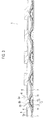
- Fig. 2 is an exploded perspective view of a switch device 1.
- Fig. 3 is a cross-sectional view of the switch device 1 shown in Fig. 2 ; and
- Fig. 4 is an enlarged view of a main part shown in Fig. 3 .
- the switch device 1 is mounted on an information input unit of an electronic apparatus such as a cellular telephone.
- the switch device 1 includes: a circuit board 2; multiple deformable contacts 3 arranged above this circuit board 2; a switch holding sheet 4 covering a surface of the circuit board 2 provided with these multiple deformable contacts 3; a light-guide sheet 5 placed over the switch holding sheet 4; multiple protrusions 6 interposed between the switch holding sheet 4 and the light-guide sheet 5; light-emitting diodes 7 arranged outside of a side surface of the light-guide sheet 5, and serving as a light source for emitting light from the side surface of the light-guide sheet 5 to the inside; and an key sheet 8 arranged above the light-guide sheet 5.
- the circuit board 2 is either a printed circuit board (PCB) or a flexible printed circuit (FPC), which is made of polyimide, polyethylene terephthalate (PET) or the like.
- the circuit board 2 includes a circuit pattern, which is formed by printing a conductive material on a surface thereof, for example. This circuit pattern includes multiple fixed contacts 10 and multiple annular contacts 11 respectively arranged around these fixed points 10.
- Each of the deformable contacts 3 is formed by processing a thin plate, which is made of metal such as stainless steel or copper having flexibility and conductivity, into a dome shape.
- a peripheral lower end of each of the dome-shaped deformable contacts 3 is arranged on the annular contact 11, and each fixed contact 10 is located inside its corresponding deformable contact 3.
- the deformable contact 3 and the fixed contact 10 collectively constitute a press switch unit 12.
- the deformable contact 3 is not connected to the fixed contact 10 in a state where a pressing force is not applied to the deformable contact 3.
- a top portion thereof elastically deforms in a way that makes the top portion sink toward the fixed contact 10 and touches the fixed contact 10.
- the deformable contact 3 is electrically connected to the fixed contact 10.
- the switch holding sheet 4 is an insulating white sheet having a thickness of 0.07 mm, which is made of polyester or olefin, for example.
- the switch holding sheet 4 includes dome-shaped projecting portions 4a located in positions corresponding to the respective deformable contacts 3, and covers the deformable contacts 3 substantially without spaces therebetween. Thereby, the switch holding sheet 4 retains the deformable contacts 3 in their respective predetermined positions on the circuit board 2.
- the sheet holding sheet 4 is bonded to the circuit board 2 and the multiple deformable contacts 3 by using an adhesive.
- the light-guide sheet 5 is made of a material having translucency such as transparent silicone, urethane, polyester, polycarbonate or methacrylic resin.
- the light-guide sheet 5 has a size substantially same as that of the circuit board 2, and has a thickness in a range of about 0.1 mm to 0.3 mm, for example.
- the light-guide sheet 5 deforms due to its own weight substantially along the undulation attributable to the deformable contacts 3 and the protrusions 6, and is arranged in an undulating state.
- the inside of the light-guide sheet 5 serves as an optical path.
- the undulating shape of the light-guide sheet 5 allows a predetermined proportion of the light to leak out of predetermined positions due to its scattering and thereby to maintain uniformity of illumination as the entire light-guide sheet 5.
- the protrusions 6 are provided between the switch holding sheet 4 and the light-guide sheet 5, and in positions corresponding to the top portions of the deformable contacts 3, respectively.
- the protrusions 6 form gaps 20 between the switch holding sheet 4 and the light-guide sheet 5 in the positions corresponding to the deformable contacts 3, respectively.
- Each of the protrusions 6 has a columnar shape.
- the height of each protrusion 6 is in a range of 0.05 mm to 0.2 mm, and the diameter thereof is in a range of 0.7 mm to 2.5 mm.
- the protrusions 6 are made of ultraviolet curable resin.
- the protrusions 6 are formed by: placing columnar ultraviolet curable resin in the positions corresponding to the top portions of the deformable contacts 3 (the top portions of the dome-shaped portions 4a in the case of the switch holding sheet 4) on the surface of the switch holding sheet 4 or the light-guide sheet 5; and curing this columnar ultraviolet curable resin by casting ultraviolet rays thereon.
- the light-emitting diodes 7 are mounted on the circuit board 2.
- the light-emitting diodes 7 are lateral light-emitting diodes configured to emit the light in a direction parallel to the surface of the circuit board 2.
- the light-emitting diodes 7 cause the light to fall incident on the one side surface 5a of the light-guide sheet 5, and to enter the inside thereof.
- Fig. 4 an example of a direction of the light traveling inside the light-guide sheet 5 from the light-emitting diode 7 is indicated with an arrow.
- the key sheet 8 includes key top portions 8a and pressing portions 8b in positions corresponding to the deformable contacts 3, respectively. Operational information is indicated on each of the key top portions 8a. Front surfaces of the key top portions 8a constitute a key surface.
- the key sheet 8 is made of a translucent material.
- the light from the light-emitting diodes 7 is caused to fall incident and enter the side of the light-guide sheet 5.
- the incident light travels inside the light-guide sheet 5 and is partially scattered. Part of this scattered light leaks out, and exits the key sheet 7.
- the key sheet 7 is illuminated so that a user can manipulate the key sheet 7 even in a dark place while visually checking the operational information on the key sheet 7.
- the protrusions 6 are provided between the switch holding sheet 4 and the light-guide sheet 5 in the positions corresponding to the deformable contacts 3, respectively. Therefore, the gaps 20 are formed around the protrusions 6. For this reason, it is highly unlikely that the light-guide sheet 5 comes into firmly adhering to the switch holding sheet 4 even when the light-guide sheet 5 has an adhesive property. Accordingly, it is possible to maintain illumination uniformity as much as possible in the structure configured to illuminate the key surface by using the light-guide sheet 5.
- the gaps 20 corresponding to the heights of the protrusions 6 is securely formed around the neighborhoods of the protrusions 6 between the switch holding sheet 4 and the light-guide sheet 5.
- This structure has an advantage for reducing the likelihood of the firm adherence between the switch holding sheet 4 and the light-guide sheet 5.
- the deformable contacts 3 have the dome shape, and the protrusions 6 are provided in the positions corresponding to the top portions of the dome-shaped deformable contacts 3, respectively.
- the pressing force is transmitted to the corresponding deformable contact 3 via the protrusion 6.
- a reaction force against the pressing force generated when the deformable contact 3 touches the fixed contact 10 is transmitted to the user via the protrusion 6. For this reason, the user can sense clear feeling when the deformable contact 3 touches the fixed contact 10.
- each deformable contact 3 is provided with only one protrusion 6, each deformable contact 3 may be provided with multiple protrusions instead.
- the protrusions 6 have the height in the range from 0.05 mm to 0.2 mm and the diameter in the range from 0.7 mm to 2.5 mm, the protrusions 6 make it possible to reliably prevent the firm adherence between the switch holding sheet 4 and the light-guide sheet 5, and to obtain satisfactory switch durability and switch feeling. The reason for this will be elaborated in the following section of examples.
- Fig. 5 is a cross-sectional view of a main part of a switch device showing a second embodiment of the present invention.
- the switch device of the second embodiment is different from the switch device of the first embodiment in that the multiple protrusions 6 are arranged between the respective deformable contacts 3 and the switch holding sheet 4.
- recess portions 4b recessed upward are formed in top portions of the dome-shaped projecting portions 4a (the positions corresponding to the top portions of the deformable contacts 3) on the switch holding sheet 4.
- the protrusions 6 are located inside the recess portions 4b.
- each protrusion 6 has a columnar shape.
- the height of each protrusion 6 is in the range of 0.05 mm to 0.2 mm, and the diameter thereof is in the range of 0.7 mm to 2.5 mm.
- Each protrusion 6 is made of polyethylene terephthalate (PET resin).
- the protrusions 6 are formed by arranging columnar PET resin in the positions corresponding to the top portions of the deformable contacts 3 on the switch holding sheet 4, i.e., in the recess portions 4b in the switch holding sheet 4. Note that this columnar PET resin may be fixed to the recess portions 4b by using any of a bonding agent and an adhesive agent, or may be simply fitted into the recess portions 4b without using any of the above.
- the gaps 21 are formed in the positions corresponding to the deformable contacts 3 between the switch holding sheet 4 and the light-guide sheet 5, like in the switch device of the first embodiment. For this reason, it is highly unlikely that the light-guide sheet 5 comes into firmly adhering to the switch holding sheet 4 even when the light-guide sheet 5 has an adhesive property. Accordingly, it is possible to maintain illumination uniformity as much as possible in the structure configured to illuminate the key surface by using the light-guide sheet 5.
- the protrusions 6 are arranged inside the recess portions 4b in the switch holding sheet 4, the protrusions 6 are securely fixed to the appropriate positions. Therefore, the protrusion 6 will not be displaced. Moreover, it is easy to carry out a manufacturing operation.
- the protrusions 6 are provided between the switch holding sheet 4 and the light-guide sheet 5.
- the protrusions 6 are provided between the switch holding sheet 4 and the deformable contacts 3.
- the gaps 20, 21 are formed in the positions corresponding to the deformable contacts 3 between the switch holding sheet 4 and the light-guide sheet 5.
- these two types of protrusions 6 may be provided simultaneously in a way that one type of protrusions 6 are provided between the switch holding sheet 4 and the light-guide sheet 5 while the other type of protrusions 6 are provided between the switch holding sheet 4 and the deformable contacts 3.
- protrusions 6 are not limited to the column-shape ones, but may also be formed in a semispherical shape.
- the light-emitting diodes 7 may be arranged so as to cause the light to fall incident on not only the one side surface 5a of the light-guide sheet 5, but also two or more side surfaces thereof.
- the light source is not limited to the light-emitting diodes 7.
- Examples 1 to 10 the presence or absence of the contact between the switch holding sheet 4 and the light-guide sheet 5, the quality of the switch durability, and the quality of the switch feeling were examined for 10 types of examples (Examples 1 to 10) which were different from one another in at least one of the material, position, height and diameter of the protrusions 6, and a comparative example (a conventional example) provided with no protrusion 6.
- the protrusions 6 were columnar throughout the examples and the conventional example 6. Details will be described below.
- ultraviolet curable resin was used in Example 1 to Example 4
- PET resin with an adhesive agent was used in Example 5 to Example 8
- PET resin without the adhesive agent was used in Examples 9 and 10.
- Example 1 the protrusions 6 were provided between the switch holding sheet 4 and the light-guide sheet 5 (indicated as Position A in Table 1). The height of the protrusions 6 was set at 0.2 mm, and the diameter of the protrusions 6 was set at 2.5 mm. In Example 2, the height of the protrusions 6 was changed to 0.15 mm, and the diameter of the protrusions 6 was changed to 2.0 mm, unlike in Example 1. In Example 3, the diameter of the protrusions 6 was set at 0.7 mm, unlike in Example 2. In Example 4, the protrusions 6 were provided between the deformable contacts 3 and the switch holding sheet 4 (indicated as Position B in Table 1). The height of the protrusions 6 was set at 0.15 mm, and the diameter of the protrusions 6 was set at 1.0 mm.
- Example 5 the protrusions 6 were provided between the switch holding sheet 4 and the light-guide sheet 5 (indicated as Position A). The height of the protrusions 6 was set at 0.05 mm, and the diameter of the protrusions 6 was set at 1.0 mm.
- Example 6 the protrusions 6 were provided between the deformable contacts 3 and the switch holding sheet 4 (indicated as Position B). The height of the protrusions 6 was set at 0.05 mm, and the diameter of the protrusions 6 was set at 0.7 mm.
- Example 7 the diameter of the protrusions 6 was changed to 2.5 mm, unlike in Example 6.
- Example 8 the diameter of the protrusions 6 was changed to 0.7 mm, unlike in Example 6.
- Example 9 the protrusions 6 were provided between the deformable contacts 3 and the switch holding sheet 4 (indicated as Position B).
- the height of the protrusions 6 was set at 0.2 mm, and the diameter of the protrusions 6 was set at 1.0 mm.
- Example 10 the height of the protrusions 6 was changed to 0.05 mm, unlike in Example 9.
- the switch feeling was tested.
- Concerning the switch feeling the quality of the feeling was tested by pressing each switch by use of a flat plate having a diameter of 5 mm.
- Table 1 the examples and the comparative example were marked with " ⁇ " when the witch feeling was satisfactory, or with "x" when the witch feeling was poor.
- the switch feeling was satisfactory in Example 1 to Example 10.
- the switch feeling was poor in the comparative example.
- the protrusions are provided in the positions corresponding to the deformable contacts between a switch holding sheet and a light-guide sheet.
- the gaps are formed around the protrusions, and reduce the likelihood of the firm adherence between the light-guide sheet and the switch holding sheet. Accordingly, the switch device capable of maintaining illumination uniformity as much as possible can be provided for an electronic apparatus and the like configured to illuminate its key surface by using the light-guide sheet.
Landscapes
- Push-Button Switches (AREA)
Abstract
Description
- The present invention relates to a switch device configured to illuminate a key surface by using a light-guide sheet, and an electronic apparatus using the same.
-
Fig. 1 shows aconventional switch device 100 disclosed in Patent Document 1. Thisswitch device 100 includes: acircuit board 102 provided with multiple fixed contacts 101; multiple deformable contacts 103 arranged above thecircuit board 102; aswitch holding sheet 104 covering a surface of the circuit board 101 provided with the multiple deformable contacts 103; a light-guide sheet 105 placed over theswitch holding sheet 104; a light-emitting diode 106 arranged outside of a side surface of this light-guide sheet 105, and serving as a light source for emitting light from the side surface to the inside; and akey sheet 107 arranged above the ligrit-guide sheet 105. - The deformable contacts 103 are formed in a dome shape, and are configured to elastically deform and come into contact with the respective fixed contacts 101 in response to pressure from above. Each deformable contact 103 and its corresponding fixed contact 101 collectively constitute a press switch unit 110.
- The
switch holding sheet 104 has a shape that makes theswitch holding sheet 104 retain the dome shapes of the deformable contacts 103 from outside, and retains the deformable contacts 103 in their predetermined positions on thecircuit board 102. - The light-
guide sheet 105 deforms due to its own weight in a way that makes the light-guide sheet 105 agree with the undulation attributable to the deformable contacts 103, and is arranged in a undulating state. - The
key sheet 107 has keytop portions 107a and pressingportions 107b, respectively, in positions corresponding to the deformable contacts 103. Operational information is indicated on each keytop portion 107a. Thekey sheet 107 is made of a light transmissive material. - The light from the light-emitting
diode 106 enters the light-guide sheet 105. The light travels inside the light-guide sheet 105, and part of the light is scattered. Part of the scattered light leaks out, and exits thekey sheet 107. In this way, thekey sheet 107 is illuminated so that a user can manipulate thekey sheet 107 even in a dark place while visually checking the operational information on thekey sheet 107. -
- Patent Document 1: Japanese Patent Application Publication No.
2007-324100 - The light-
guide sheet 105 has a function to transmit a pressing force from a key surface to theswitch holding sheet 104, a function to cause the light to pass through its inside, and the like. As the light-guide sheet 105, a silicone-based sheet or a urethane-based sheet is used. However, since these sheet materials have adhesive properties, and the light-guide sheet 105 easily adheres (sticks) to theswitch holding sheet 104. When the light-guide sheet 105 sticks to theswitch holding sheet 104, the light is scattered in the portion where the light-guide sheet 105 adheres thereto. This causes the light to leak out of a position other than a desired position (i.e., a position in which the light is intended to scatter). Therefore, this leak causes a problem of a loss of illumination uniformity on the key surface. - The present invention has been made for solving the aforementioned problem, and an object thereof is to provide a switch device configured to illuminate a key surface by using a light-guide sheet, which is capable of maintaining illumination uniformity as much as possible.
- A first aspect of the present invention is a switch device including: a circuit board provided with a fixed contact; a deformable contact arranged above the circuit board, and configured to deform and come into contact with the fixed contact in response to pressure from above; a switch holding sheet covering a surface of the circuit board provided with the deformable contact, and configured to retain the deformable contact on the circuit board; a light-guide sheet placed over the switch holding sheet, and allowing light to pass through its inside; a light source configured to cause the light to fall incident and enter the inside of the light-guide sheet; and a protrusion provided between the switch holding sheet and the light-guide sheet or between the deformable contact and the light-guide sheet in a position corresponding to the deformable contact, and forming a gap between the switch holding sheet and the light-guide sheet.
- The deformable contact may be formed in a dome shape, and the protrusion may be provided in a position corresponding to a top portion of the dome-shaped deformable contact.
- The height of the protrusion may be in a range of 0.05 mm to 0.2 mm, and the diameter of the protrusion may be in a range of 0.7 mm to 2.5 mm.
- The protrusion may have a columnar shape or a semispherical shape.
- A second aspect of the present invention is an electronic apparatus including the foregoing switch device.
-
- [
Fig. 1] Fig. 1 is a cross-sectional view of a conventional switch device. - [
Fig. 2] Fig. 2 is an exploded perspective view of a switch device of a first embodiment of the present invention. - [
Fig. 3] Fig. 3 is a cross-sectional view of the switch device of the first embodiment of the present invention. - [
Fig. 4] Fig. 4 is an enlarged view of a main part of the switch device shown inFig. 3 . - [
Fig. 5] Fig. 5 is a cross-sectional view of a main part of a switch device of a second embodiment of the present invention. - Embodiments of the present invention will be described below based on the drawings.
-
Fig. 2 to Fig. 4 show a first embodiment of the present invention.Fig. 2 is an exploded perspective view of a switch device 1.Fig. 3 is a cross-sectional view of the switch device 1 shown inFig. 2 ; andFig. 4 is an enlarged view of a main part shown inFig. 3 . - As shown in
Fig. 2 andFig. 3 , the switch device 1 is mounted on an information input unit of an electronic apparatus such as a cellular telephone. The switch device 1 includes: acircuit board 2; multipledeformable contacts 3 arranged above thiscircuit board 2; aswitch holding sheet 4 covering a surface of thecircuit board 2 provided with these multipledeformable contacts 3; a light-guide sheet 5 placed over theswitch holding sheet 4;multiple protrusions 6 interposed between theswitch holding sheet 4 and the light-guide sheet 5; light-emitting diodes 7 arranged outside of a side surface of the light-guide sheet 5, and serving as a light source for emitting light from the side surface of the light-guide sheet 5 to the inside; and ankey sheet 8 arranged above the light-guide sheet 5. - The
circuit board 2 is either a printed circuit board (PCB) or a flexible printed circuit (FPC), which is made of polyimide, polyethylene terephthalate (PET) or the like. Thecircuit board 2 includes a circuit pattern, which is formed by printing a conductive material on a surface thereof, for example. This circuit pattern includes multiplefixed contacts 10 and multipleannular contacts 11 respectively arranged around thesefixed points 10. - Each of the
deformable contacts 3 is formed by processing a thin plate, which is made of metal such as stainless steel or copper having flexibility and conductivity, into a dome shape. A peripheral lower end of each of the dome-shapeddeformable contacts 3 is arranged on theannular contact 11, and each fixedcontact 10 is located inside its correspondingdeformable contact 3. Thedeformable contact 3 and the fixedcontact 10 collectively constitute apress switch unit 12. Moreover, thedeformable contact 3 is not connected to the fixedcontact 10 in a state where a pressing force is not applied to thedeformable contact 3. When the pressing force acts on thedeformable contact 3, a top portion thereof elastically deforms in a way that makes the top portion sink toward thefixed contact 10 and touches thefixed contact 10. As a consequence, thedeformable contact 3 is electrically connected to the fixedcontact 10. - The
switch holding sheet 4 is an insulating white sheet having a thickness of 0.07 mm, which is made of polyester or olefin, for example. Theswitch holding sheet 4 includes dome-shaped projectingportions 4a located in positions corresponding to the respectivedeformable contacts 3, and covers thedeformable contacts 3 substantially without spaces therebetween. Thereby, theswitch holding sheet 4 retains thedeformable contacts 3 in their respective predetermined positions on thecircuit board 2. Thesheet holding sheet 4 is bonded to thecircuit board 2 and the multipledeformable contacts 3 by using an adhesive. - The light-
guide sheet 5 is made of a material having translucency such as transparent silicone, urethane, polyester, polycarbonate or methacrylic resin. The light-guide sheet 5 has a size substantially same as that of thecircuit board 2, and has a thickness in a range of about 0.1 mm to 0.3 mm, for example. The light-guide sheet 5 deforms due to its own weight substantially along the undulation attributable to thedeformable contacts 3 and theprotrusions 6, and is arranged in an undulating state. The inside of the light-guide sheet 5 serves as an optical path. The undulating shape of the light-guide sheet 5 allows a predetermined proportion of the light to leak out of predetermined positions due to its scattering and thereby to maintain uniformity of illumination as the entire light-guide sheet 5. - The
protrusions 6 are provided between theswitch holding sheet 4 and the light-guide sheet 5, and in positions corresponding to the top portions of thedeformable contacts 3, respectively. Theprotrusions 6form gaps 20 between theswitch holding sheet 4 and the light-guide sheet 5 in the positions corresponding to thedeformable contacts 3, respectively. Each of theprotrusions 6 has a columnar shape. The height of eachprotrusion 6 is in a range of 0.05 mm to 0.2 mm, and the diameter thereof is in a range of 0.7 mm to 2.5 mm. Theprotrusions 6 are made of ultraviolet curable resin. Specifically, theprotrusions 6 are formed by: placing columnar ultraviolet curable resin in the positions corresponding to the top portions of the deformable contacts 3 (the top portions of the dome-shapedportions 4a in the case of the switch holding sheet 4) on the surface of theswitch holding sheet 4 or the light-guide sheet 5; and curing this columnar ultraviolet curable resin by casting ultraviolet rays thereon. - The light-emitting
diodes 7 are mounted on thecircuit board 2. The light-emittingdiodes 7 are lateral light-emitting diodes configured to emit the light in a direction parallel to the surface of thecircuit board 2. The light-emittingdiodes 7 cause the light to fall incident on the oneside surface 5a of the light-guide sheet 5, and to enter the inside thereof. InFig. 4 , an example of a direction of the light traveling inside the light-guide sheet 5 from the light-emittingdiode 7 is indicated with an arrow. - The
key sheet 8 includes keytop portions 8a andpressing portions 8b in positions corresponding to thedeformable contacts 3, respectively. Operational information is indicated on each of the keytop portions 8a. Front surfaces of the keytop portions 8a constitute a key surface. Thekey sheet 8 is made of a translucent material. - In the switch device 1 having the above-described configuration, the light from the light-emitting
diodes 7 is caused to fall incident and enter the side of the light-guide sheet 5. The incident light travels inside the light-guide sheet 5 and is partially scattered. Part of this scattered light leaks out, and exits thekey sheet 7. Thereby, thekey sheet 7 is illuminated so that a user can manipulate thekey sheet 7 even in a dark place while visually checking the operational information on thekey sheet 7. - As described above, the
protrusions 6 are provided between theswitch holding sheet 4 and the light-guide sheet 5 in the positions corresponding to thedeformable contacts 3, respectively. Therefore, thegaps 20 are formed around theprotrusions 6. For this reason, it is highly unlikely that the light-guide sheet 5 comes into firmly adhering to theswitch holding sheet 4 even when the light-guide sheet 5 has an adhesive property. Accordingly, it is possible to maintain illumination uniformity as much as possible in the structure configured to illuminate the key surface by using the light-guide sheet 5. - Moreover, the
gaps 20 corresponding to the heights of theprotrusions 6 is securely formed around the neighborhoods of theprotrusions 6 between theswitch holding sheet 4 and the light-guide sheet 5. This structure has an advantage for reducing the likelihood of the firm adherence between theswitch holding sheet 4 and the light-guide sheet 5. - The
deformable contacts 3 have the dome shape, and theprotrusions 6 are provided in the positions corresponding to the top portions of the dome-shapeddeformable contacts 3, respectively. When the user presses the position corresponding to the top portion of one of the dome-shapeddeformable contacts 3, the pressing force is transmitted to the correspondingdeformable contact 3 via theprotrusion 6. Further, a reaction force against the pressing force generated when thedeformable contact 3 touches the fixedcontact 10 is transmitted to the user via theprotrusion 6. For this reason, the user can sense clear feeling when thedeformable contact 3 touches the fixedcontact 10. - Although the
protrusions 6 are provided in the positions corresponding to the top portions of thedeformable contacts 3, theprotrusions 6 may be located in any arbitrary positions as long as the arbitrary positions enable thegaps 20 to be formed between theswitch holding sheet 4 and the light-guide sheet 5. Although eachdeformable contact 3 is provided with only oneprotrusion 6, eachdeformable contact 3 may be provided with multiple protrusions instead. - Further, because the
protrusions 6 have the height in the range from 0.05 mm to 0.2 mm and the diameter in the range from 0.7 mm to 2.5 mm, theprotrusions 6 make it possible to reliably prevent the firm adherence between theswitch holding sheet 4 and the light-guide sheet 5, and to obtain satisfactory switch durability and switch feeling. The reason for this will be elaborated in the following section of examples. -
Fig. 5 is a cross-sectional view of a main part of a switch device showing a second embodiment of the present invention. As shown inFig. 5 , the switch device of the second embodiment is different from the switch device of the first embodiment in that themultiple protrusions 6 are arranged between the respectivedeformable contacts 3 and theswitch holding sheet 4. To be more precise,recess portions 4b recessed upward are formed in top portions of the dome-shaped projectingportions 4a (the positions corresponding to the top portions of the deformable contacts 3) on theswitch holding sheet 4. Theprotrusions 6 are located inside therecess portions 4b. Even while an upper surface of theswitch holding sheet 4 located on the upper surfaces of theprotrusions 6 contacts the light-guide sheet 5,gaps 21 are formed between theswitch holding sheet 4 and the light-guide sheet 5 around theprotrusions 6 by therecess portions 4b and theprotrusions 6, respectively. Eachprotrusion 6 has a columnar shape. The height of eachprotrusion 6 is in the range of 0.05 mm to 0.2 mm, and the diameter thereof is in the range of 0.7 mm to 2.5 mm. Eachprotrusion 6 is made of polyethylene terephthalate (PET resin). Theprotrusions 6 are formed by arranging columnar PET resin in the positions corresponding to the top portions of thedeformable contacts 3 on theswitch holding sheet 4, i.e., in therecess portions 4b in theswitch holding sheet 4. Note that this columnar PET resin may be fixed to therecess portions 4b by using any of a bonding agent and an adhesive agent, or may be simply fitted into therecess portions 4b without using any of the above. - The rest of the configuration is similar to that in the above-described first embodiment. Accordingly, the same constituents are denoted by the same reference numerals, and description thereof will be omitted.
- In this switch device of the second embodiment, the
gaps 21 are formed in the positions corresponding to thedeformable contacts 3 between theswitch holding sheet 4 and the light-guide sheet 5, like in the switch device of the first embodiment. For this reason, it is highly unlikely that the light-guide sheet 5 comes into firmly adhering to theswitch holding sheet 4 even when the light-guide sheet 5 has an adhesive property. Accordingly, it is possible to maintain illumination uniformity as much as possible in the structure configured to illuminate the key surface by using the light-guide sheet 5. - Because the
protrusions 6 are arranged inside therecess portions 4b in theswitch holding sheet 4, theprotrusions 6 are securely fixed to the appropriate positions. Therefore, theprotrusion 6 will not be displaced. Moreover, it is easy to carry out a manufacturing operation. - In the first embodiment, the
protrusions 6 are provided between theswitch holding sheet 4 and the light-guide sheet 5. In the second embodiment, theprotrusions 6 are provided between theswitch holding sheet 4 and thedeformable contacts 3. By providing theprotrusions 6, thegaps deformable contacts 3 between theswitch holding sheet 4 and the light-guide sheet 5. Instead, however, these two types ofprotrusions 6 may be provided simultaneously in a way that one type ofprotrusions 6 are provided between theswitch holding sheet 4 and the light-guide sheet 5 while the other type ofprotrusions 6 are provided between theswitch holding sheet 4 and thedeformable contacts 3. - The above-described
protrusions 6 are not limited to the column-shape ones, but may also be formed in a semispherical shape. - In the first embodiment and the second embodiment, the light-emitting
diodes 7 may be arranged so as to cause the light to fall incident on not only the oneside surface 5a of the light-guide sheet 5, but also two or more side surfaces thereof. Moreover, the light source is not limited to the light-emittingdiodes 7. - As shown on Table 1 given below, the presence or absence of the contact between the
switch holding sheet 4 and the light-guide sheet 5, the quality of the switch durability, and the quality of the switch feeling were examined for 10 types of examples (Examples 1 to 10) which were different from one another in at least one of the material, position, height and diameter of theprotrusions 6, and a comparative example (a conventional example) provided with noprotrusion 6. Theprotrusions 6 were columnar throughout the examples and the conventional example 6. Details will be described below.
- As for the material of the
protrusions 6, ultraviolet curable resin was used in Example 1 to Example 4, PET resin with an adhesive agent was used in Example 5 to Example 8, and PET resin without the adhesive agent was used in Examples 9 and 10. - In Example 1, the
protrusions 6 were provided between theswitch holding sheet 4 and the light-guide sheet 5 (indicated as Position A in Table 1). The height of theprotrusions 6 was set at 0.2 mm, and the diameter of theprotrusions 6 was set at 2.5 mm. In Example 2, the height of theprotrusions 6 was changed to 0.15 mm, and the diameter of theprotrusions 6 was changed to 2.0 mm, unlike in Example 1. In Example 3, the diameter of theprotrusions 6 was set at 0.7 mm, unlike in Example 2. In Example 4, theprotrusions 6 were provided between thedeformable contacts 3 and the switch holding sheet 4 (indicated as Position B in Table 1). The height of theprotrusions 6 was set at 0.15 mm, and the diameter of theprotrusions 6 was set at 1.0 mm. - In Example 5, the
protrusions 6 were provided between theswitch holding sheet 4 and the light-guide sheet 5 (indicated as Position A). The height of theprotrusions 6 was set at 0.05 mm, and the diameter of theprotrusions 6 was set at 1.0 mm. In Example 6, theprotrusions 6 were provided between thedeformable contacts 3 and the switch holding sheet 4 (indicated as Position B). The height of theprotrusions 6 was set at 0.05 mm, and the diameter of theprotrusions 6 was set at 0.7 mm. In Example 7, the diameter of theprotrusions 6 was changed to 2.5 mm, unlike in Example 6. In Example 8, the diameter of theprotrusions 6 was changed to 0.7 mm, unlike in Example 6. - In Example 9, the
protrusions 6 were provided between thedeformable contacts 3 and the switch holding sheet 4 (indicated as Position B). The height of theprotrusions 6 was set at 0.2 mm, and the diameter of theprotrusions 6 was set at 1.0 mm. In Example 10, the height of theprotrusions 6 was changed to 0.05 mm, unlike in Example 9. - First, the presence or absence of the contact between the
switch holding sheet 4 and the light-guide sheet 5 around theprotrusions 6 was examined. As shown in Table 1, no contact between theswitch holding sheet 4 and the light-guide sheet 5 was observed in any of Example 1 to Example 10. On the other hand, the contact between theswitch holding sheet 4 and the light-guide sheet 5 was observed in the comparative example. One may consider that in the comparative example, the contact occurred because noprotrusions 6 were provided. - Next, the switch feeling was tested. Concerning the switch feeling, the quality of the feeling was tested by pressing each switch by use of a flat plate having a diameter of 5 mm. In Table 1, the examples and the comparative example were marked with "○" when the witch feeling was satisfactory, or with "x" when the witch feeling was poor. As shown in this table, the switch feeling was satisfactory in Example 1 to Example 10. On the other hand, the switch feeling was poor in the comparative example. One may consider that in the comparative example, the switch feeling was poor because no
protrusion 6 was provided. - Next, the quality of the switch durability was tested. As shown in Table 1, the switch durability was favorable in any of Example 1 to Example 10.
- The above-mentioned results of the experiments proves that the contact between the
switch holding sheet 4 and the light-guide sheet 5 can be securely prevented, and the satisfactory switch durability and switch feeling can be obtained, as long as the height of the protrusions is in the range of 0.05 mm to 0.2 mm and the diameter thereof is in the range of 0.7 mm to 2.5 mm. - In the switch device, the protrusions are provided in the positions corresponding to the deformable contacts between a switch holding sheet and a light-guide sheet. The gaps are formed around the protrusions, and reduce the likelihood of the firm adherence between the light-guide sheet and the switch holding sheet. Accordingly, the switch device capable of maintaining illumination uniformity as much as possible can be provided for an electronic apparatus and the like configured to illuminate its key surface by using the light-guide sheet.
Claims (5)
- A switch device comprising:a circuit board provided with a fixed contact;a deformable contact arranged above the circuit board, and configured to deform and come into contact with the fixed contact in response to pressure from above;a switch holding sheet covering a surface of the circuit board provided with the deformable contact, and configured to retain the deformable contact on the circuit board;a light-guide sheet placed over the switch holding sheet, and allowing light to pass through its inside;a light source configured to cause the light to fall incident and enter the inside of the light-guide sheet; anda protrusion provided between the switch holding sheet and the light-guide sheet or between the deformable contact and the light-guide sheet in a position corresponding to the deformable contact, and forming a gap between the switch holding sheet and the light-guide sheet.
- The switch device according to claim 1,
wherein the deformable contact is formed in a dome shape, and
the protrusion is provided in a position corresponding to a top portion of the dome shape of the deformable contact. - The switch device according to claim 1 or claim 2,
wherein a height of the protrusion is in a range of 0.05 mm to 0.2 mm, and
a diameter of the protrusion is in a range of 0.7 mm to 2.5 mm. - The switch device according to any one of claim 1 to claim 3,
wherein the protrusion has any of a columnar shape and a semispherical shape. - An electronic apparatus comprising the switch device according to any one of claim 1 to claim 4.
Applications Claiming Priority (2)
| Application Number | Priority Date | Filing Date | Title |
|---|---|---|---|
| JP2009123964 | 2009-05-22 | ||
| PCT/JP2010/058656 WO2010134605A1 (en) | 2009-05-22 | 2010-05-21 | Switch device and electronic equipment |
Publications (2)
| Publication Number | Publication Date |
|---|---|
| EP2434510A1 true EP2434510A1 (en) | 2012-03-28 |
| EP2434510A4 EP2434510A4 (en) | 2014-03-05 |
Family
ID=43126282
Family Applications (1)
| Application Number | Title | Priority Date | Filing Date |
|---|---|---|---|
| EP10777836.7A Withdrawn EP2434510A4 (en) | 2009-05-22 | 2010-05-21 | Switch device and electronic equipment |
Country Status (5)
| Country | Link |
|---|---|
| US (1) | US20120061226A1 (en) |
| EP (1) | EP2434510A4 (en) |
| JP (1) | JPWO2010134605A1 (en) |
| CN (1) | CN102428533A (en) |
| WO (1) | WO2010134605A1 (en) |
Families Citing this family (5)
| Publication number | Priority date | Publication date | Assignee | Title |
|---|---|---|---|---|
| US20140090967A1 (en) * | 2011-05-10 | 2014-04-03 | Covac Co., Ltd. | Two-step switch |
| US20130037400A1 (en) * | 2011-08-12 | 2013-02-14 | Shi-Chiung Chen | Substrates for flexible keyboards and methods of manufacturing the same |
| JP5321701B2 (en) * | 2012-01-19 | 2013-10-23 | Smk株式会社 | Push switch and manufacturing method thereof |
| CN103578831B (en) * | 2012-08-09 | 2016-07-06 | 光宝电子(广州)有限公司 | Pressure type backlight button structure |
| US11229737B2 (en) | 2014-09-10 | 2022-01-25 | Becton, Dickinson And Company | Activation system and method for on-body medical devices |
Family Cites Families (9)
| Publication number | Priority date | Publication date | Assignee | Title |
|---|---|---|---|---|
| KR100692742B1 (en) * | 2005-05-13 | 2007-03-09 | 삼성전자주식회사 | Keypad and Keypad Assembly with Light Guide Layer |
| JP4917840B2 (en) | 2006-06-05 | 2012-04-18 | シチズン電子株式会社 | Seat switch module |
| TWM309710U (en) * | 2006-08-11 | 2007-04-11 | Altek Corp | Pushbutton structure |
| JP5193463B2 (en) * | 2006-12-26 | 2013-05-08 | 株式会社フジクラ | Switch module |
| JP2008204769A (en) * | 2007-02-20 | 2008-09-04 | Matsushita Electric Ind Co Ltd | Light guide sheet and movable contact body and switch using the same |
| US7718910B2 (en) * | 2007-06-20 | 2010-05-18 | Panasonic Corporation | Movable contact assembly and switch using the same |
| JP2009021142A (en) * | 2007-07-13 | 2009-01-29 | Citizen Electronics Co Ltd | Sheet switch module |
| JP4892435B2 (en) * | 2007-08-10 | 2012-03-07 | アルプス電気株式会社 | Movable contact unit for switch and switch device using the same |
| TWM333750U (en) * | 2008-01-03 | 2008-06-01 | Ichia Tech Inc | Metal panel structure with multiple color layers of hole-array |
-
2010
- 2010-05-21 EP EP10777836.7A patent/EP2434510A4/en not_active Withdrawn
- 2010-05-21 WO PCT/JP2010/058656 patent/WO2010134605A1/en not_active Ceased
- 2010-05-21 JP JP2011514464A patent/JPWO2010134605A1/en active Pending
- 2010-05-21 CN CN2010800220976A patent/CN102428533A/en active Pending
-
2011
- 2011-11-18 US US13/299,519 patent/US20120061226A1/en not_active Abandoned
Also Published As
| Publication number | Publication date |
|---|---|
| US20120061226A1 (en) | 2012-03-15 |
| WO2010134605A1 (en) | 2010-11-25 |
| CN102428533A (en) | 2012-04-25 |
| EP2434510A4 (en) | 2014-03-05 |
| JPWO2010134605A1 (en) | 2012-11-12 |
Similar Documents
| Publication | Publication Date | Title |
|---|---|---|
| EP1724800B1 (en) | Key pad and keypad assembly | |
| KR100988099B1 (en) | Light guide sheet and movable contact body and switch using the same | |
| JP2011175981A (en) | Key pad assembly | |
| US8212787B2 (en) | Movable contact body and switch using same | |
| US20120061226A1 (en) | Switch device and electronic apparatus | |
| JP2009094036A (en) | Movable contact body and switch using the same | |
| US7718910B2 (en) | Movable contact assembly and switch using the same | |
| JP2010135160A (en) | Light guiding sheet and movable contact body using the same | |
| JP5023971B2 (en) | Movable contact with light guiding function and input device using the same | |
| KR101021820B1 (en) | Movable contact unit for switch and switch device using same | |
| JP2008269889A (en) | Illumination member for switch and switch device using it | |
| JP2010040385A (en) | Switch device | |
| US20130088847A1 (en) | Light-guiding sheet and movable contact body using same | |
| US8337028B2 (en) | Light guide sheet and movable contact assembly using the same | |
| JP2008243655A (en) | Movable contact body and illuminated panel switch constructed using the same | |
| JP2016081587A (en) | Movable contact body and switch using the same | |
| JP2010192275A (en) | Light guide sheet switch | |
| KR200441448Y1 (en) | A light guide plate sheet having a pressing projection and a keypad assembly including the light guide plate sheet | |
| JP2012243711A (en) | Sheet with contact spring, and switch device | |
| JP2011113699A (en) | Movable contact and switch using this | |
| JP2010212173A (en) | Movable contact body, method of manufacturing the same, and switch using the same | |
| JP2012109139A (en) | Light guide sheet and movable contact body using the same | |
| JP2011165417A (en) | Light guide sheet and movable contact using this | |
| JP2013073793A (en) | Light guide sheet and movable contact body with light guide sheet using the same | |
| JP2010073317A (en) | Light guide sheet and movable contact using this |
Legal Events
| Date | Code | Title | Description |
|---|---|---|---|
| PUAI | Public reference made under article 153(3) epc to a published international application that has entered the european phase |
Free format text: ORIGINAL CODE: 0009012 |
|
| 17P | Request for examination filed |
Effective date: 20111219 |
|
| AK | Designated contracting states |
Kind code of ref document: A1 Designated state(s): AL AT BE BG CH CY CZ DE DK EE ES FI FR GB GR HR HU IE IS IT LI LT LU LV MC MK MT NL NO PL PT RO SE SI SK SM TR |
|
| DAX | Request for extension of the european patent (deleted) | ||
| A4 | Supplementary search report drawn up and despatched |
Effective date: 20140205 |
|
| RIC1 | Information provided on ipc code assigned before grant |
Ipc: H01H 9/16 20060101ALI20140130BHEP Ipc: H01H 13/02 20060101AFI20140130BHEP Ipc: H01H 13/702 20060101ALI20140130BHEP Ipc: H01H 13/83 20060101ALI20140130BHEP |
|
| STAA | Information on the status of an ep patent application or granted ep patent |
Free format text: STATUS: THE APPLICATION IS DEEMED TO BE WITHDRAWN |
|
| 18D | Application deemed to be withdrawn |
Effective date: 20140904 |