EP2434360A1 - Bewegungssteuerungssystem - Google Patents
Bewegungssteuerungssystem Download PDFInfo
- Publication number
- EP2434360A1 EP2434360A1 EP10178336A EP10178336A EP2434360A1 EP 2434360 A1 EP2434360 A1 EP 2434360A1 EP 10178336 A EP10178336 A EP 10178336A EP 10178336 A EP10178336 A EP 10178336A EP 2434360 A1 EP2434360 A1 EP 2434360A1
- Authority
- EP
- European Patent Office
- Prior art keywords
- trace
- time
- data
- motion
- motion control
- Prior art date
- Legal status (The legal status is an assumption and is not a legal conclusion. Google has not performed a legal analysis and makes no representation as to the accuracy of the status listed.)
- Granted
Links
Images
Classifications
-
- G—PHYSICS
- G05—CONTROLLING; REGULATING
- G05B—CONTROL OR REGULATING SYSTEMS IN GENERAL; FUNCTIONAL ELEMENTS OF SUCH SYSTEMS; MONITORING OR TESTING ARRANGEMENTS FOR SUCH SYSTEMS OR ELEMENTS
- G05B19/00—Program-control systems
- G05B19/02—Program-control systems electric
- G05B19/18—Numerical control [NC], i.e. automatically operating machines, in particular machine tools, e.g. in a manufacturing environment, so as to execute positioning, movement or co-ordinated operations by means of program data in numerical form
- G05B19/414—Structure of the control system, e.g. common controller or multiprocessor systems, interface to servo, programmable interface controller
- G05B19/4148—Structure of the control system, e.g. common controller or multiprocessor systems, interface to servo, programmable interface controller characterised by using several processors for different functions, distributed (real-time) systems
-
- G—PHYSICS
- G05—CONTROLLING; REGULATING
- G05B—CONTROL OR REGULATING SYSTEMS IN GENERAL; FUNCTIONAL ELEMENTS OF SUCH SYSTEMS; MONITORING OR TESTING ARRANGEMENTS FOR SUCH SYSTEMS OR ELEMENTS
- G05B2219/00—Program-control systems
- G05B2219/20—Pc systems
- G05B2219/25—Pc structure of the system
- G05B2219/25472—Synchronise controllers, sensors, measurement with data bus
-
- G—PHYSICS
- G05—CONTROLLING; REGULATING
- G05B—CONTROL OR REGULATING SYSTEMS IN GENERAL; FUNCTIONAL ELEMENTS OF SUCH SYSTEMS; MONITORING OR TESTING ARRANGEMENTS FOR SUCH SYSTEMS OR ELEMENTS
- G05B2219/00—Program-control systems
- G05B2219/30—Nc systems
- G05B2219/35—Nc in input of data, input till input file format
- G05B2219/35291—Record history, log, journal, audit of machine operation
-
- G—PHYSICS
- G05—CONTROLLING; REGULATING
- G05B—CONTROL OR REGULATING SYSTEMS IN GENERAL; FUNCTIONAL ELEMENTS OF SUCH SYSTEMS; MONITORING OR TESTING ARRANGEMENTS FOR SUCH SYSTEMS OR ELEMENTS
- G05B2219/00—Program-control systems
- G05B2219/30—Nc systems
- G05B2219/37—Measurements
- G05B2219/37532—Synchronized data acquisition
Definitions
- the invention relates to a motion control system.
- a motion control system has, for example, a plurality of drives.
- data can be stored in a trace.
- An object of the invention is to improve the readability of stored data.
- the motion control system includes e.g. a first drive and a second drive. To control and / or control the drives a motion control for these drives is available.
- the motion controls of the drives are linked by a data communication, for example, a central unit for control and / or control may be present.
- the motion control system relates, for example, to a production machine or a machine tool. Examples of such machines are: grinding machine, milling machine, lathe, printing press, press, crane, packaging machine, etc.
- the readability of the data of the traces can be improved.
- components which may have a trace are: programmable logic controller, master computer, motion control, cam controller, register control, etc. These components are various parts of an automation system, which, for example, the Automation of a machine tool or a production machine is used.
- a motion control system includes a first motion controller, a second motion controller, and a data bus.
- the data bus is, for example, a bus system based on Profibus, Ethernet or CAN bus.
- the motion control system further includes a global time.
- the global time is, for example, a system time on which times different components in the system, can be related. Global time can also be the only time in the system. Furthermore, the global time can be divided into different cycle times.
- first trace data are collected.
- second motion control second trace data are collected.
- trace data are: actual current, actual voltage, control word, alarm signal, actual speed value, actual position value, ignition pulses, temperature, pressure, etc.
- the trace data of the motion controls have a time stamp.
- the time of the time stamp from the first motion control may be equal to or different from the time of the time stamp of the second motion control. If the times are different at least it is known in which relation the times are related to one another, so that the trace data of different motion controls can be related to one another.
- the times may be set in relation to a global time. In one embodiment of the system, the global time is, for example, the time of the first as well as the second motion control.
- the global time can be transmitted from a master timer via a data bus to the motion controllers.
- the trace data advantageously has a time stamp dependent on the global time. This relates to first trace data from the first motion control and second trace data from the second motion control.
- the trace data of the motion controllers can be stored in a trace memory in the respective motion controller and can be read from there to be used with others Combine trace data of other motion controls.
- the trace data of the motion controllers can also be transmitted, for example, directly from the motion controller to an external trace.
- the separate measurements e.g. graphically easier to superimpose in order to display them in a window.
- the trace data from the different measurements can also be mathematically processed (eg addition, subtraction, Correlation functions, FFT, etc.).
- the representation of the trace data and / or their processing takes place, for example, in an engineering system or in a host computer system.
- the engineering system also serves, for example, the following tasks: programming of motion sequences, programming of a bus system, configuration of an automation system, etc.
- a motion controller may be configured such that it has at least one microprocessor (in particular a CPU). Measurements of the trace data are carried out in particular with the aid of at least one microprocessor.
- the measurement data is given a time stamp, which makes it possible, for example by means of an engineering system, to represent trace data as a signal in the correct time to each other.
- time stamps which are assigned to the measurement
- the communication topology therefore does not need to have any influence on the time-synchronized, distributed trace, as long as the communication system masters the topology.
- timestamps are directly through the motion control or assigned by the sensor, wherein the motion control and / or the sensor receives a time signal of a data bus. By this reception in particular a synchronization to the global time is possible.
- the first motion control has a first trace and the second motion control has a second trace, wherein first trace data of the first trace are linked to second trace data of the second trace.
- a link already results from a time stamp whose time is linked to a global time. Another link results, for example, through a mathematical processing of both trace data. It is then possible, for example, to record signals simultaneously on different control and / or regulating devices and to display resulting data in a time-synchronized diagram.
- At least two motion controls are coupled to one another via a synchronization function.
- a first motion control is thus associated with a second or each further motion control via a function (here, for example, a synchronization function).
- the movement controls have, for example, a master or a control system. Functions can be synchronized via a bus system.
- the global time it is possible to realize a distributed trace with precise temporal representation of the signals to each other.
- the signals can be assigned very precisely in time, and thus also displayed in a common trace with a high-resolution time base become.
- Parameterization of the trace takes place, for example, by means of an engineering system.
- the start of one or more traces can be initiated via a trigger signal on the bus.
- a cross-project start is also feasible, eg in connection with cross-project synchronization.
- trace data of different motion controls are displayed in a time-synchronized manner in a graphic. This is possible through a synchronized data bus.
- the system time is to be transmitted via the bus, which serves for the synchronization.
- the triggering of one or more traces can be triggered by a trigger.
- the trigger can be an internal software signal or an external HW trigger signal. With only one trigger different separate traces can be started.
- the trigger signal can also be displayed in a graphic, for example, together with the trace signals.
- time stamps with a global time dependency enables simultaneous, jointly triggered recording of signals on different automation systems and time-synchronized representation and / or joint representation in a graphical trace.
- Triggers can also be transmitted over a second communication path, but the timing accuracy of the trigger events is not decisive if the trace values themselves have a time stamp as described.
- the data is recorded in a ring buffer.
- the trace can be started in any motion control of the entire system or even in a selection of motion controls.
- the trace can also be in a programmable logic controller (PLC), or in a control system or engineering system Trace data of different devices (eg sensor, actuator, control, regulation) are transferred via the data bus with a time stamp to the trace.
- PLC programmable logic controller
- Trace data of different devices eg sensor, actuator, control, regulation
- the time stamp is therefore assigned as close as possible to the source of the data creation and provided with a time stamp, which depends on a global time of a larger system with multiple communication participants.
- the engineering system stores trace data, an evaluation can also take place there.
- the recorded data is sent to the engineering system with a time stamp. There, the data can be evaluated with the time stamps with respect to their relation to each other and transmitted in a common time base.
- the trigger signal from a motion controller or from a CPU, at which the trigger occurs are sent via UDP broadcast to further in particular all other devices in the system. If a trigger signal occurs or has been communicated, the trace values from the trigger are written from the ring buffer to the trace memory, or the values are no longer overwritten as of the trigger signal.
- a trigger is transmitted via a data bus to the (in particular all) devices connected to the data bus.
- a time information (in particular a time stamp) can be transmitted simultaneously with the trigger signal. This time information can be used in conjunction with the global time to determine when the trigger actually occurred. For this purpose, for example, a running time of the trigger information is used via the data bus.
- An automation device or a device on the data bus can therefrom, for example, derive an information as to when a data acquisition can be ended in a time-synchronized manner (this represents a trace end).
- the time synchronization relates in particular to the cycle time of the data bus.
- the trigger does not have to be time-synchronized because the values can initially be stored independently of it.
- a synchronization of trace data takes place via the global time-dependent time stamps.
- the advantageous properties of a synchronized communication system with accurate time information about the whole system become clear.
- the temporal resolution / accuracy can thus improve the accuracy of time synchronization in an isochronous communication system such as e.g. PROFINET IRT (IRT: Isochronous Realtime Ethernet).
- a motion control system also each relate to a corresponding method for operating a motion control system.
- a first motion controller is connected to a second motion controller via a data bus.
- First trace data of the first motion control have a time stamp dependent on a global time.
- second trace data of the second motion control has a time stamp dependent on the global time, the different trace data being correlated via the time stamp.
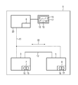
- the illustration according to the figure shows a first movement control 3 and a second movement control 5.
- the movement controls 3, 5 may also be drive systems, which also have a converter for energizing an electric machine.
- the first motion controller 3 has a first trace 7.
- the second movement control has a second trace 9.
- the traces 7 and 9 can record signals, values and data available in the motion controllers 3 and 5.
- the first trace 7 has trace data 15, which are provided with a time stamp 16. This is shown in the figure by intersecting circles.
- the second trace 9 has trace data 17 with timestamps 16.
- the movement controls 3, 5 are connected to each other via a data bus 11 with respect to data.
- the motion controllers 3 and 5 can be connected to one another via a further data line 12 (eg Profinet IRT).
- the motion controls 3 and 5 are connected to an engineering system 20 data technology.
- the engineering system 20 has a trace 8.
- the trace data 15 and 17, which have a time stamp are stored, after which they were transmitted via the data bus 11 to the engineering system 20.
- data to be traced can be transmitted directly from the motion controllers to the engineering system 20 in order to store them there in the trace 8.
- the data is already transferred with the time stamp, which is based on a global time, via the data bus 11 to the engineering system 20.
- the global time 22 is also communicated via the bus 11.
- a data transmission of recording data can take place via a separate Ethernet connection, which represents a data bus, or also via a Profinet line 12.
- trigger transmission may occur over an asynchronous communication path (e.g., User Data Protocol (UDP) on Profinet thread).
- UDP User Data Protocol
- the engineering system 20 has a monitor 18 for displaying the trace data 15 and 17, these being in a common graph over a time axis for the timestamp data 16 are shown. This is a time-synchronized representation of data from different devices, here motion controls.
Landscapes
- Engineering & Computer Science (AREA)
- Human Computer Interaction (AREA)
- Manufacturing & Machinery (AREA)
- Physics & Mathematics (AREA)
- General Physics & Mathematics (AREA)
- Automation & Control Theory (AREA)
- Testing And Monitoring For Control Systems (AREA)
- Pinball Game Machines (AREA)
- Arrangements For Transmission Of Measured Signals (AREA)
Abstract
Description
- Die Erfindung betrifft ein Bewegungssteuerungssystem. Ein Bewegungssteuerungssystem weist beispielweise eine Vielzahl von Antrieben auf. Zur Überwachung von Funktionen und/oder des Verhaltens des Bewegungssteuerungssystems können Daten in einem Trace gespeichert werden.
- Eine Aufgabe der Erfindung ist es die Auswertbarkeit gespeicherter Daten zu verbessern.
- Eine Lösung der Aufgabe ergibt sich bei einem Bewegungssteuerungssystem bzw. eine entsprechenden Betriebsverfahren mit Merkmalen nach einem der Ansprüche 1 bis 11.
- Das Bewegungssteuerungssystem weist z.B. einen ersten Antrieb und einen zweiten Antrieb auf. Zur Regelung und/oder Steuerung der Antriebe ist eine Bewegungssteuerung für diese Antriebe vorhanden. Die Bewegungssteuerungen der Antriebe sind über eine Datenkommunikation verknüpft, wobei beispielsweise auch eine Zentraleinheit zur Regelung und/oder Steuerung vorhanden sein kann. Das Bewegungssteuerungssystem betrifft beispielsweise eine Produktionsmaschine oder auch eine Werkzeugmaschine. Beispiele für derartige Maschinen sind: Schleifmaschine, Fräsmaschine, Drehbank, Druckmaschine, Presse, Kran, Verpackungsmaschine, usw.
- Durch eine Zeitsynchronisation unterschiedlicher Traces unterschiedlicher Komponenten des Bewegungssteuerungssystem kann die Auswertbarkeit der Daten der Traces verbessert werden. Beispiele unterschiedlicher Komponenten, welche einen Trace aufweisen können sind: Speicherprogrammierbare Steuerung, Leitrechner, Bewegungssteuerung, Nockensteuerwerk, Registerregelung, usw. Diese Komponenten sind verschiedene Teile eines Automatisierungssystems, welches beispielsweise der Automatisierung einer Werkzeugmaschine oder einer Produktionsmaschine dient.
- In einer Ausprägung weist ein Bewegungssteuerungssystem eine erste Bewegungssteuerung, eine zweite Bewegungsteuerung und einen Datenbus auf. Der Datenbus ist Beispielsweise ein Bussystem auf Basis von Profibus, Ethernet oder CAN-Bus. Das Bewegungssteuerungssystem weist ferner eine Globalzeit auf. Die Globalzeit ist beispielsweise eine Systemzeit auf welche Zeiten unterschiedlicher Komponenten im System, in Bezug gesetzt werden können. Die Globalzeit kann auch die einzige Zeit im System sein. Ferner kann die Globalzeit in unterschiedliche Taktzeiten unterteilt sein.
- Mittels der ersten Bewegungssteuerung werden erste Tracedaten gesammelt. Mittels der zweiten Bewegungssteuerung werden zweite Tracedaten gesammelt. Beispiele für Tracedaten sind: Iststrom, Istspannung, Steuerwort, Alarmsignal, Drehzahlistwert, Lageistwert, Zündimpulse, Temperatur, Druck, usw. Die Tracedaten der Bewegungssteuerungen weisen einen Zeitstempel auf. Die Zeit der Zeitstempel von der ersten Bewegungssteuerung kann gleich oder ungleich der Zeit der Zeitstempel der zweiten Bewegungssteuerung sein. Sind die Zeiten unterschiedlich ist zumindest bekannt, in welcher Relation die Zeiten zueinander stehen, so dass die Tracedaten unterschiedlicher Bewegungssteuerungen zueinander in Relation gesetzt werden können. Beispielsweise können die Zeiten in Relation zu einer Globalzeit gesetzt werden. In einer Ausprägung des Systems ist die Globalzeit beispielsweise die Zeit der ersten wie auch der zweiten Bewegungssteuerung. Die Globalzeit kann von einem Masterzeitgeber über einen Datenbus an die Bewegungssteuerungen übertragen werden. Die Tracedaten weisen vorteilhaft einen von der Globalzeit abhängigen Zeitstempel auf. Dies betrifft erste Tracedaten von der ersten Bewegungssteuerung und zweite Tracedaten von der zweiten Bewegungssteuerung. Die Tracedaten der Bewegungssteuerungen können in einem Tracespeicher in der jeweiligen Bewegungssteuerung gespeichert sein und von dort ausgelesen werden um diese mit anderen Tracedaten weiterer Bewegungssteuerungen zu kombinieren. Die Tracedaten der Bewegungssteuerungen können beispielsweise auch direkt von der Bewegungssteuerung an einen externen Trace übertragen werden.
- Haben verschiedene Tracedaten eine gemeinsame Zeitbasis, so können diese leichter miteinander in Verbindung gesetzt werden. Mittels der Zeitsynchronisation getrennter Messungen (Tracedaten) können die getrennten Messungen z.B. graphisch einfacher überlagert werden, um diese in einem Fenster darzustellen. Vor einer Darstellung können die Tracedaten aus den unterschiedlichen Messungen (von einer ersten Bewegungssteuerung, von einer weiteren Bewegungssteuerung, ... bzw. von einem ersten Sensor, von einem weiteren Sensor, ...) auch mathematisch verarbeitet werden (z.B. Addition, Subtraktion, Korrelationsfunktionen, FFT, usw.). Die Darstellung der Tracedaten und/oder deren Verarbeitung erfolgt beispielsweise in einem Engineeringsystem oder auch in einem Leitrechnersystem. Das Engineeringsystem dient ferner beispielsweise folgenden Aufgaben: Programmierung von Bewegungsabläufen, Programmierung eines Bussystems, Projektierung eines Automatisierungssystems, usw.
- Eine Bewegungssteuerung kann derart ausgebildet sein, dass diese zumindest einen Mikroprozessor (insbesondere eine CPU) aufweist. Messungen der Tracedaten erfolgen insbesondere unter Zuhilfenahme zumindest eines Mikroprozessors. Den Messdaten wird ein Zeitstempel mitgegeben, wodurch es beispielsweise mittels eines Engineeringsystems möglich ist, Tracedaten als Signal zeitrichtig zueinander darzustellen.
- Durch die Nutzung von Zeitstempeln, welche zur Messung vergeben werden, kann der Einfluss von Kommunikationstopologien auf die Auswertemöglichkeit der gemessenen Daten reduziert werden. Die Kommunikationstopologie braucht damit keinen Einfluss auf den zeitsynchronisierten, verteilten Trace haben, sofern das Kommunikationssystem die Topologie beherrscht. Zeitstempel werden beispielsweise direkt durch die Bewegungssteuerung bzw. durch den Sensor vergeben, wobei die Bewegungssteuerung und/oder der Sensor ein Zeitsignal eines Datenbusses empfängt. Durch diesen Empfang ist insbesondere eine Synchronisation auf die Globalzeit möglich.
- In einer Ausgestaltung des Bewegungssteuerungssystems weist die erste Bewegungssteuerung einen ersten Trace und die zweite Bewegungssteuerung einen zweiten Trace auf, wobei erste Tracedaten des ersten Trace mit zweiten Tracedaten des zweiten Trace verknüpft sind. Eine Verknüpfung ergibt sich bereits durch einen Zeitstempel, dessen Zeit mit einer Globalzeit gekoppelt ist. Eine weitere Verknüpfung ergibt sich beispielsweise durch eine mathematische Verarbeitung beider Tracedaten. Danach ist es beispielsweise möglich Signale Daten gleichzeitig auf unterschiedlichen Steuerungs- und/oder Regelungseinrichtungen aufzuzeichnen und daraus resultierende Daten zeitsynchron in einer Grafik darzustellen.
- In einer Ausgestaltung des Bewegungssteuerungssystems sind zumindest zwei Bewegungssteuerungen über eine Gleichlauffunktion miteinander gekoppelt. Eine erste Bewegungssteuerung ist demnach mit einer zweiten oder jeder weiteren Bewegungssteuerung über eine Funktion (hier z.B. eine Gleichlaufsfunktion) verknüpft. Die Bewegungsteuerungen weisen beispielsweise einen Master auf oder auch ein Leitsystem. Über ein Bussystem können Funktionen Bewegungssteuerungen synchronisiert werden.
- In einem synchronisierten Bussystem mit Übertragung der Systemzeit (Globalzeit) sind unter Kenntnis von Verzögerungszeiten (Delayzeiten) einzelne Busanschaltungen und damit auch die Steuerungssysteme zeitlich zueinander wohl definiert, bzw. genau bestimmbar.
- Durch die Verwendung der Globalzeit ist es möglich einen verteilten Trace mit genauer zeitlicher Darstellung der Signale zueinander zu realisieren. Die Signale können sehr genau zeitlich zugeordnet werden, und damit auch in einem gemeinsamen Trace mit einer hoch auflösenden Zeitbasis dargestellt werden. Eine Parametrierung des Trace erfolgt beispielsweise mittels eines Engineeringsystems. Der Start eines oder mehrerer Traces kann über ein Triggersignal auf dem Bus initiiert werden. Auch ein Projektübergreifender Start ist durchführbar, z.B. in Verbindung mit einem projektübergreifenden Gleichlauf.
- In einer Ausgestaltung des Bewegungssteuerungssystems werden in einem Graphik Tracedaten unterschiedlicher Bewegungssteuerungen zeitsynchronisiert dargestellt. Dies wird durch einen synchronisierten Datenbus möglich. Über den Bus ist die Systemzeit zu übertragen, welche der Synchronisation dient.
- Den Start eines oder mehrerer Traces kann ein Trigger auslösen. Der Trigger kann ein internes Softwaresignal oder auch ein externes HW-Triggersignal sein. Mit nur einem Trigger können unterschiedliche separate Traces gestartet werden. Das Triggersignal kann beispielsweise in einer Graphik auch zusammen mit den Tracesignalen dargestellt werden.
- Durch die Verwendung von Zeitstempeln mit einer Abhängigkeit von einer Globalzeit ist ein gleichzeitiges, gemeinsam getriggertes Aufzeichnen von Signalen auf verschiedenen Automatisierungssystemen und eine zeitsynchronisierte Darstellung und/oder gemeinsame Darstellung in einem grafischen Trace möglich.
- Trigger können auch über einen zweiten Kommunikationsweg übertragen werden, die zeitliche Genauigkeit der Triggerereignisse ist dabei dann nicht entscheidend, wenn die Tracewerte wie beschrieben selbst einen Zeitstempel besitzen.
- In einer Ausgestaltung des Systems erfolgt nach Starten des Traces die Aufzeichnung der Daten in einem Ringpuffer. Der Trace kann in jeder Bewegungssteuerung des Gesamtsystems oder auch nur in einer Auswahl von Bewegungssteuerungen gestartet werden. Der Trace kann sich auch in einer Speicherprogrammierbaren Steuerung (SPS), oder in einem Leitsystem oder Engineeringsystem befinden, wobei Tracedaten unterschiedlicher Geräte (z.B. Sensor, Aktor, Steuerung, Regelung) über den Datenbus mit einem Zeitstempel an den Trace übertragen werden. Der Zeitstempel wird also möglichst nahe an der Quelle der Datenentstehung vergeben und mit einem Zeitstempel versehen, welcher von einer Globalzeit eines größeren Systems mit mehreren Kommunikationsteilnehmern abhängt.
- Speichert das Engineeringsystem Tracedaten, so kann dort auch eine Auswertung erfolgen. Die aufgezeichneten Daten werden mit Zeitstempel an das Engineeringsystem gesendet. Dort können die Daten mit den Zeitstempeln bzgl. ihrer Relation zueinander ausgewertet und in eine gemeinsame Zeitbasis übertragen werden.
- In einer Ausgestaltung kann das Triggersignal von einer Bewegungssteuerung bzw. von einer CPU, an welcher der Trigger auftritt, über UDP Broadcast an weitere insbesondere alle anderen Geräte im System gesendet werden. Falls ein Triggersignal auftritt, bzw. kommuniziert wurde, werden die Tracewerte ab dem Trigger aus dem Ringpuffer in den Tracespeicher geschrieben, bzw. die Werte werden ab dem Triggersignal nicht mehr überschrieben.
- In einer Ausgestaltung wird ein Trigger (Triggersignal) über einen Datenbus an die (insbesondere alle) mit dem Datenbus verbundenen Geräte übermittelt. Dabei kann gleichzeitig mit dem Triggersignal eine Zeitinformation (insbesondere ein Zeitstempel) übertragen werden. Durch diese Zeitinformation kann in Verbindung mit der Globalzeit ermittelt werden, wann der Trigger tatsächlich aufgetreten ist. Hierfür wird beispielsweise eine Laufzeit der Triggerinformation über den Datenbus verwendet. Ein Automatisierungsgerät bzw. ein Gerät am Datenbus kann hieraus beispielsweise eine Information ableiten, wann eine Datenerfassung zeitsynchron beendet werden kann (dies stellt ein Traceende dar). Die Zeitsynchronität bezieht sich dabei insbesondere auf die Taktzeit des Datenbusses.
- Durch die Verwendung von Zeitstempeln muss der Trigger nicht zeitsynchronisiert werden, da die Werte zunächst unabhängig davon bereits gespeichert werden können. Eine Synchronisation von Tracedaten erfolgt über die globalzeitabhängigen Zeitstempel. Hier werden die vorteilhaften Eigenschaften eines synchronisierten Kommunikationssystems mit einer genauen Zeitinformation über das ganze System deutlich. Dabei ist eine Separierung der Kommunikation des Triggerereignisses vom Aufzeichnungs- und Auswertungsvorgang möglich. Die zeitliche Auflösung / Genauigkeit kann damit der Genauigkeit der Zeitsnychronisation in einem isochronen Kommunikationssystem wie z.B. PROFINET IRT entsprechen (IRT: Isochrones Realtime Ethernet).
- Die beschriebenen Variationen eines Bewegungssteuerungssystem betreffen jeweils auch ein entsprechendes Verfahren zum Betrieb eines Bewegungssteuerungssystems. Bei einem Verfahren zur Bewegungssteuerung ist eine erste Bewegungssteuerung mit einer zweiten Bewegungsteuerung über einen Datenbus verbunden. Erste Tracedaten der ersten Bewegungssteuerung weisen einen von einer Globalzeit abhängigen Zeitstempel auf. Ebenso weisen zweite Tracedaten der zweiten Bewegungssteuerung einen von der Globalzeit abhängigen Zeitstempel auf, wobei die unterschiedlichen Tracedaten über den Zeitstempel korreliert sind.
- Im Folgenden wird die Erfindung beispielhaft anhand einer Figur beschrieben, welche bei einem Bewegungssteuerungssystem eine Aufgabenzuordnung bzw. eine Kommunikationsstruktur mit einem zeitsynchronen Trace zeigt.
- Die Darstellung gemäß der Figur zeigt eine erste Bewegungssteuerung 3 und eine zweite Bewegungssteuerung 5. Bei den Bewegungssteuerungen 3, 5 kann es sich auch um Antriebssysteme handeln, welche auch einen Stromrichter zum Bestromen einer elektrischen Maschine aufweisen. Die erste Bewegungssteuerung 3 weist einen ersten Trace 7 auf. Die zweite Bewegungssteuerung weist einen zweiten Trace 9 auf. Die Traces 7 und 9 können Signale, Werte und Daten aufzeichnen, welche in den Bewegungssteuerungen 3 und 5 zur Verfügung stehen. Der erste Trace 7 weist Tracedaten 15 auf, welche mit einem Zeitstempel 16 versehen sind. Dies ist in der Figur durch überschneidende Kreise dargestellt. Ebenso weist der zweite Trace 9 Tracedaten 17 mit Zeitstempeln 16 auf. Die Bewegungssteuerungen 3, 5 sind über einen Datenbus 11 miteinander datentechnisch verbunden. Ebenso können die Bewegungssteuerungen 3 und 5 über eine weitere Datenleitung 12 (z.B. Profinet IRT) miteinander verbunden sein. Über den Datenbus 11 sind die Bewegungssteuerungen 3 und 5 mit einem Engineeringsystem 20 datentechnisch verbunden. Das Engineeringsystem 20 weist einen Trace 8 auf. In diesen Trace 8 können beispielsweise die Tracedaten 15 und 17, welche einen Zeitstempel aufweisen, gespeichert werden, nach dem diese über den Datenbus 11 zum Engineeringsystem 20 übertragen wurden. Weist nur das Engineeringsystem 20 einen Trace 8 auf und sind keine Traces in den Bewegungssteuerungen vorhanden (in der Figur nicht dargestellt), so können zu tracende Daten direkt von den Bewegungssteuerungen zum Engineeringsystem 20 übertragen werden um diese dort im Trace 8 zu speichern. Die Daten werden dabei schon mit dem Zeitstempel, welcher sich an einer Globalzeit orientiert, über den Datenbus 11 zum Engineeringsystem 20 übertragen. Auch die Globalzeit 22 wird über den Bus 11 kommuniziert.
- Eine Datenübertragung von Aufzeichnungsdaten (Tracedaten) kann über eine separate Ethernet Verbindung, welche einen Datenbus darstellt, oder auch über einen Profinet-Strang 12 erfolgen.
- Eine Triggerübertragung kann beispielsweise über einen asynchronen Kommunikationspfad erfolgen (z.B. UDP (User Data Protocol) auf Profinet-Strang).
- Das Engineeringsystem 20 weist einen Monitor 18 zur Darstellung der Tracedaten 15 und 17 auf, wobei diese in einer gemeinsamen Graphik über eine Zeitachse für die Zeitstempeldaten 16 dargestellt sind. Dies dient einer zeitsynchronen Darstellung von Daten aus unterschiedlichen Geräten, hier Bewegungssteuerungen.
Claims (11)
- Bewegungssteuerungssystem (1), welches eine erste Bewegungssteuerung (3), eine zweite Bewegungsteuerung (5), einen Datenbus (11) und eine Globalzeit aufweist, wobei erste Tracedaten (15) der ersten Bewegungssteuerung (3) einen von der Globalzeit abhängigen Zeitstempel aufweisen und wobei zweite Tracedaten (17) der zweiten Bewegungssteuerung (5) einen von der Globalzeit abhängigen Zeitstempel aufweisen.
- Bewegungssteuerungssystem (1) nach Anspruch 1, wobei die erste Bewegungssteuerung (3) einen ersten Trace (7) aufweist, wobei die zweite Bewegungssteuerung (5) einen zweiten Trace (9) aufweist, wobei die ersten Tracedaten (15) des ersten Trace (7) mit den zweiten Tracedaten (17) des zweiten Trace (9) verknüpft sind.
- Bewegungssteuerungssystem (1) nach Anspruch 1 oder 2, wobei die erste Bewegungssteuerung (3) mit der zweiten Bewegungssteuerung (5) über eine Gleichlaufsfunktion miteinander verknüpft sind.
- Bewegungssteuerungssystem (1) nach Anspruch 1 bis 3, wobei in einer Graphik Tracedaten (15,17) unterschiedlicher Bewegungssteuerungen (3,5) zeitsynchronisiert dargestellt sind.
- Bewegungssteuerungssystem (1) nach Anspruch 1 bis 4, wobei der Datenbus synchronisiert ist, wobei der Datenbus (11) eine Systemzeit aufweist, welche der Synchronisation dient.
- Bewegungssteuerungssystem (1) nach Anspruch 1 bis 5, wobei ein Trigger zum Start des ersten und/oder zweiten Trace (7,9) vorgesehen ist.
- Bewegungssteuerungssystem (1) nach Anspruch 1 bis 6, wobei ein Ringpuffer zur Speicherung von Tracedaten (15,17) vorgesehen ist.
- Bewegungssteuerungssystem (1) nach Anspruch 1 bis 7, wobei ein Engineeringsystem (20) Tracedaten (15,17) speichert.
- Bewegungssteuerungssystem (1) nach einem der Ansprüche 1 bis 8, wobei ein Trigger über einen Datenbus an ein Gerät übermittelbar ist, wobei der Trigger eine Zeitinformation aufweist, wobei insbesondere aus der Zeitinformation ein Traceende ermittelbar ist, wobei das Traceende insbesondere zeitsynchronisiert ist.
- Verfahren zur Bewegungssteuerung wobei eine erste Bewegungssteuerung (3) mit einer zweiten Bewegungsteuerung (5) über einen Datenbus verbunden ist, wobei erste Tracedaten (15) der ersten Bewegungssteuerung (3) einen von einer Globalzeit abhängigen Zeitstempel aufweisen und wobei zweite Tracedaten (17) der zweiten Bewegungssteuerung (5) einen von der Globalzeit abhängigen Zeitstempel aufweisen, wobei die unterschiedlichen Tracedaten (15,17) über den Zeitstempel verknüpft werden.
- Verfahren nach Anspruch 10, wobei ein Tracesystem (30) nach einem der Ansprüche 1 bis 9 verwendet wird.
Priority Applications (3)
| Application Number | Priority Date | Filing Date | Title |
|---|---|---|---|
| EP10178336.3A EP2434360B1 (de) | 2010-09-22 | 2010-09-22 | Bewegungssteuerungssystem |
| CN201110268204.XA CN102411338B (zh) | 2010-09-22 | 2011-09-09 | 运动控制系统 |
| US13/240,184 US20120245712A1 (en) | 2010-09-22 | 2011-09-22 | Motion control system |
Applications Claiming Priority (1)
| Application Number | Priority Date | Filing Date | Title |
|---|---|---|---|
| EP10178336.3A EP2434360B1 (de) | 2010-09-22 | 2010-09-22 | Bewegungssteuerungssystem |
Publications (2)
| Publication Number | Publication Date |
|---|---|
| EP2434360A1 true EP2434360A1 (de) | 2012-03-28 |
| EP2434360B1 EP2434360B1 (de) | 2020-01-08 |
Family
ID=43587269
Family Applications (1)
| Application Number | Title | Priority Date | Filing Date |
|---|---|---|---|
| EP10178336.3A Active EP2434360B1 (de) | 2010-09-22 | 2010-09-22 | Bewegungssteuerungssystem |
Country Status (3)
| Country | Link |
|---|---|
| US (1) | US20120245712A1 (de) |
| EP (1) | EP2434360B1 (de) |
| CN (1) | CN102411338B (de) |
Cited By (2)
| Publication number | Priority date | Publication date | Assignee | Title |
|---|---|---|---|---|
| WO2019002091A1 (de) * | 2017-06-28 | 2019-01-03 | Trumpf Werkzeugmaschinen Gmbh + Co. Kg | Werkzeugmaschine mit einer mehrzahl von sensoren |
| DE102019135493A1 (de) * | 2019-12-20 | 2021-06-24 | Trumpf Werkzeugmaschinen Gmbh + Co. Kg | Verfahren und System zur Synchronisation von Signalen |
Families Citing this family (2)
| Publication number | Priority date | Publication date | Assignee | Title |
|---|---|---|---|---|
| JP7268287B2 (ja) * | 2018-03-12 | 2023-05-08 | オムロン株式会社 | 制御システム、制御方法、および制御プログラム |
| JP6805453B1 (ja) * | 2019-11-26 | 2020-12-23 | 株式会社安川電機 | 電力変換装置、制御装置、データ蓄積装置及びデータ蓄積方法 |
Citations (6)
| Publication number | Priority date | Publication date | Assignee | Title |
|---|---|---|---|---|
| US5774377A (en) * | 1991-07-30 | 1998-06-30 | Hewlett-Packard Company | Method and apparatus for monitoring a subsystem within a distributed system for providing an archive of events within a certain time of a trap condition |
| WO2006042799A2 (de) * | 2004-10-15 | 2006-04-27 | Siemens Aktiengesellschaft | Verfahren und einrichtung zur analyse eines technischen prozesses |
| DE102004052555A1 (de) * | 2004-10-29 | 2006-05-04 | Bosch Rexroth Ag | Verfahren zum Austauschen von Daten zwischen Teilnehmern aus verschiedenen Netzwerken |
| EP1768006A2 (de) * | 2005-09-26 | 2007-03-28 | Siemens Aktiengesellschaft | Verfahren und Vorrichtung zur Erleichterung der Einstellung von Systemen, bei welchen Objekte bewegt werden |
| EP1892598A2 (de) * | 2006-08-22 | 2008-02-27 | Robert Bosch Gmbh | Automatisierungssystem und Verfahren zur Taktzeit-, Prozess- und/oder Maschinenoptimierung |
| DE102007015762A1 (de) * | 2007-03-30 | 2008-10-02 | It-Designers Gmbh | Datenaufzeichnungssystem und Verfahren zur Erfassung von Daten mittels eines Datenaufzeichnungssystems |
Family Cites Families (13)
| Publication number | Priority date | Publication date | Assignee | Title |
|---|---|---|---|---|
| US6826590B1 (en) * | 1996-08-23 | 2004-11-30 | Fieldbus Foundation | Block-oriented control system on high speed ethernet |
| US5790114A (en) * | 1996-10-04 | 1998-08-04 | Microtouch Systems, Inc. | Electronic whiteboard with multi-functional user interface |
| US5896524A (en) * | 1997-02-06 | 1999-04-20 | Digital Equipment Corporation | Off-line clock synchronization for multiprocessor event traces |
| US20020095613A1 (en) * | 1997-07-25 | 2002-07-18 | Shinya Matsuoka | Synchronizing motion and time-based data for transfer between a server and a client |
| US6785893B2 (en) * | 2000-11-30 | 2004-08-31 | Microsoft Corporation | Operating system event tracker having separate storage for interrupt and non-interrupt events and flushing the third memory when timeout and memory full occur |
| DE10113260B4 (de) * | 2001-03-16 | 2005-10-20 | Siemens Ag | Synchrones, getaktetes Kommunikationssystem mit Relativuhr und Verfahren zum Aufbau eines solchen Systems |
| US7437201B2 (en) * | 2003-01-14 | 2008-10-14 | Cullen Christopher P | Electric motor controller |
| DE10343963A1 (de) * | 2003-09-19 | 2005-04-14 | Siemens Ag | Bereitstellung von Diagnoseinformationen |
| DE10357824A1 (de) * | 2003-12-09 | 2005-07-14 | Kuka Roboter Gmbh | Verfahren und Vorrichtung zum Betreiben zusammenarbeitender unterschiedlicher Geräte |
| US7149606B2 (en) * | 2005-03-01 | 2006-12-12 | Fanul Robotics America, Inc. | Synchronizing controllers linked by a communications network |
| DE502005011032D1 (de) * | 2005-07-28 | 2011-04-14 | Siemens Ag | Verfahren zur Optimierung der Bandbreitenausnutzung bei Bussystemen |
| US7840285B2 (en) * | 2005-10-28 | 2010-11-23 | Invensys Systems, Inc. | Sequence of events recorder facility for an industrial process control environment |
| US8626980B2 (en) * | 2009-05-20 | 2014-01-07 | Chronologic Pty. Ltd. | High density, low jitter, synchronous USB expansion |
-
2010
- 2010-09-22 EP EP10178336.3A patent/EP2434360B1/de active Active
-
2011
- 2011-09-09 CN CN201110268204.XA patent/CN102411338B/zh active Active
- 2011-09-22 US US13/240,184 patent/US20120245712A1/en not_active Abandoned
Patent Citations (6)
| Publication number | Priority date | Publication date | Assignee | Title |
|---|---|---|---|---|
| US5774377A (en) * | 1991-07-30 | 1998-06-30 | Hewlett-Packard Company | Method and apparatus for monitoring a subsystem within a distributed system for providing an archive of events within a certain time of a trap condition |
| WO2006042799A2 (de) * | 2004-10-15 | 2006-04-27 | Siemens Aktiengesellschaft | Verfahren und einrichtung zur analyse eines technischen prozesses |
| DE102004052555A1 (de) * | 2004-10-29 | 2006-05-04 | Bosch Rexroth Ag | Verfahren zum Austauschen von Daten zwischen Teilnehmern aus verschiedenen Netzwerken |
| EP1768006A2 (de) * | 2005-09-26 | 2007-03-28 | Siemens Aktiengesellschaft | Verfahren und Vorrichtung zur Erleichterung der Einstellung von Systemen, bei welchen Objekte bewegt werden |
| EP1892598A2 (de) * | 2006-08-22 | 2008-02-27 | Robert Bosch Gmbh | Automatisierungssystem und Verfahren zur Taktzeit-, Prozess- und/oder Maschinenoptimierung |
| DE102007015762A1 (de) * | 2007-03-30 | 2008-10-02 | It-Designers Gmbh | Datenaufzeichnungssystem und Verfahren zur Erfassung von Daten mittels eines Datenaufzeichnungssystems |
Cited By (3)
| Publication number | Priority date | Publication date | Assignee | Title |
|---|---|---|---|---|
| WO2019002091A1 (de) * | 2017-06-28 | 2019-01-03 | Trumpf Werkzeugmaschinen Gmbh + Co. Kg | Werkzeugmaschine mit einer mehrzahl von sensoren |
| DE102019135493A1 (de) * | 2019-12-20 | 2021-06-24 | Trumpf Werkzeugmaschinen Gmbh + Co. Kg | Verfahren und System zur Synchronisation von Signalen |
| WO2021123265A1 (de) | 2019-12-20 | 2021-06-24 | Trumpf Werkzeugmaschinen Gmbh + Co. Kg | Verfahren und system zur synchronisation von signalen |
Also Published As
| Publication number | Publication date |
|---|---|
| EP2434360B1 (de) | 2020-01-08 |
| CN102411338B (zh) | 2014-12-10 |
| CN102411338A (zh) | 2012-04-11 |
| US20120245712A1 (en) | 2012-09-27 |
Similar Documents
| Publication | Publication Date | Title |
|---|---|---|
| DE10223723B4 (de) | Ereigniserfassungssystem für eine Folge von Ereignissen und Verfahren zum Erkennen von Ereignissen in einem Prozesssteuerungssystem | |
| DE102009017681B4 (de) | Verfahren und Kommunikationssystem zum Ermitteln des Zeitpunktes eines Ereignisses in einem IO-Gerät | |
| WO2008064763A1 (de) | Fehlerprotokollierungsverfahren für eine beschichtungsanlage | |
| DE102009045386A1 (de) | Verfahren zum Betreiben eines Feldbus-Interface | |
| EP3646123B1 (de) | Werkzeugmaschine mit einer mehrzahl von sensoren und entsprechendes verfahren | |
| EP2225537A2 (de) | Feldgerät und verfahren zur überprüfung der kalibrierung eines feldgeräts | |
| EP2434360B1 (de) | Bewegungssteuerungssystem | |
| WO2002075509A2 (de) | Synchrones, getaktetes kommunikationssystem mit relativuhr und verfahren zum aufbau eines solchen systems | |
| DE102014111733A1 (de) | Verfahren zum Parametrieren eines Feldgerätes | |
| EP1253494B1 (de) | Steuer- und/oder Regelungssystem mit Feldbus | |
| DE102009046041A1 (de) | Anordnung zur Bedienung von Feldgeräten in der Automatisierungstechnik mittels eines Konfigurier-/Managementsystems | |
| WO2010118864A1 (de) | Verfahren zum bereitstellen eine information über ein verschleiss einer komponente einer maschine und verfahren zum bereitstellen eines ersatzalgorithmus | |
| EP2434357B1 (de) | Tracesystem für Technologiedaten und/oder Programmereignisse | |
| EP3566102A1 (de) | Selbstkonfigurierende überwachungseinrichtung für ein auf einem industriellen datenkommunikationsnetzwerk basierendes automatisierungssystem | |
| WO1999050722A1 (de) | Verfahren zur synchronisation einer lokalen auf eine zentrale zeitbasis, und vorrichtung zur durchführung des verfahrens mit bevorzugen verwendungen | |
| EP3267272B1 (de) | Vorrichtung und verfahren zur datenübertragung | |
| EP3182652B1 (de) | Verfahren zur periodischen erfassung von messwerten in einem echtzeitcomputersystem sowie echtzeitcomputersystem | |
| DE19815647C2 (de) | Verfahren zur Synchronisation einer lokalen auf eine zentrale Zeitbasis, und Vorrichtung zur Durchführung des Verfahrens mit bevorzugten Verwendungen | |
| EP2746892B1 (de) | Automatisierte Anlage und Verfahren zur Synchronisation einer automatisierten Anlage | |
| EP2287693B1 (de) | Verfahren zum synchronen Erfassen und Aufzeichnen von Prozess- und/oder Zustandsdaten sowie Automatisierungssystem | |
| DE112015006524B4 (de) | Numerische Steuerungseinrichtung | |
| DE102014225867A1 (de) | Vorrichtung und Verfahren zur Überprüfung eines Arbeitstaktsignals einer Positionsmesseinrichtung | |
| EP3004995B1 (de) | Verfahren zum erfassen einer senderortszeit in einem empfänger | |
| DE102006053866A1 (de) | Verfahren zum Betreiben eines nach dem Blockmodell arbeitenden modularen Feldgerätes der Automatisierungstechnik | |
| EP2455830A1 (de) | Verfahren zur Erfassung von Eingangssignaländerungen |
Legal Events
| Date | Code | Title | Description |
|---|---|---|---|
| PUAI | Public reference made under article 153(3) epc to a published international application that has entered the european phase |
Free format text: ORIGINAL CODE: 0009012 |
|
| AK | Designated contracting states |
Kind code of ref document: A1 Designated state(s): AL AT BE BG CH CY CZ DE DK EE ES FI FR GB GR HR HU IE IS IT LI LT LU LV MC MK MT NL NO PL PT RO SE SI SK SM TR |
|
| AX | Request for extension of the european patent |
Extension state: BA ME RS |
|
| 17P | Request for examination filed |
Effective date: 20120806 |
|
| RAP1 | Party data changed (applicant data changed or rights of an application transferred) |
Owner name: SIEMENS AKTIENGESELLSCHAFT |
|
| 17Q | First examination report despatched |
Effective date: 20160331 |
|
| RAP1 | Party data changed (applicant data changed or rights of an application transferred) |
Owner name: SIEMENS AKTIENGESELLSCHAFT |
|
| GRAP | Despatch of communication of intention to grant a patent |
Free format text: ORIGINAL CODE: EPIDOSNIGR1 |
|
| STAA | Information on the status of an ep patent application or granted ep patent |
Free format text: STATUS: GRANT OF PATENT IS INTENDED |
|
| RIN1 | Information on inventor provided before grant (corrected) |
Inventor name: SCHLINKERT, JOCHEN Inventor name: WAGNER, PETER Inventor name: MOEHRING, RAINER Inventor name: VOLLMANN, JOERG |
|
| INTG | Intention to grant announced |
Effective date: 20190906 |
|
| GRAS | Grant fee paid |
Free format text: ORIGINAL CODE: EPIDOSNIGR3 |
|
| GRAA | (expected) grant |
Free format text: ORIGINAL CODE: 0009210 |
|
| STAA | Information on the status of an ep patent application or granted ep patent |
Free format text: STATUS: THE PATENT HAS BEEN GRANTED |
|
| AK | Designated contracting states |
Kind code of ref document: B1 Designated state(s): AL AT BE BG CH CY CZ DE DK EE ES FI FR GB GR HR HU IE IS IT LI LT LU LV MC MK MT NL NO PL PT RO SE SI SK SM TR |
|
| REG | Reference to a national code |
Ref country code: GB Ref legal event code: FG4D Free format text: NOT ENGLISH |
|
| REG | Reference to a national code |
Ref country code: CH Ref legal event code: EP |
|
| REG | Reference to a national code |
Ref country code: IE Ref legal event code: FG4D Free format text: LANGUAGE OF EP DOCUMENT: GERMAN |
|
| REG | Reference to a national code |
Ref country code: DE Ref legal event code: R096 Ref document number: 502010016442 Country of ref document: DE |
|
| REG | Reference to a national code |
Ref country code: AT Ref legal event code: REF Ref document number: 1223473 Country of ref document: AT Kind code of ref document: T Effective date: 20200215 |
|
| REG | Reference to a national code |
Ref country code: NL Ref legal event code: MP Effective date: 20200108 |
|
| REG | Reference to a national code |
Ref country code: LT Ref legal event code: MG4D |
|
| PG25 | Lapsed in a contracting state [announced via postgrant information from national office to epo] |
Ref country code: NL Free format text: LAPSE BECAUSE OF FAILURE TO SUBMIT A TRANSLATION OF THE DESCRIPTION OR TO PAY THE FEE WITHIN THE PRESCRIBED TIME-LIMIT Effective date: 20200108 Ref country code: PT Free format text: LAPSE BECAUSE OF FAILURE TO SUBMIT A TRANSLATION OF THE DESCRIPTION OR TO PAY THE FEE WITHIN THE PRESCRIBED TIME-LIMIT Effective date: 20200531 Ref country code: NO Free format text: LAPSE BECAUSE OF FAILURE TO SUBMIT A TRANSLATION OF THE DESCRIPTION OR TO PAY THE FEE WITHIN THE PRESCRIBED TIME-LIMIT Effective date: 20200408 Ref country code: FI Free format text: LAPSE BECAUSE OF FAILURE TO SUBMIT A TRANSLATION OF THE DESCRIPTION OR TO PAY THE FEE WITHIN THE PRESCRIBED TIME-LIMIT Effective date: 20200108 Ref country code: LT Free format text: LAPSE BECAUSE OF FAILURE TO SUBMIT A TRANSLATION OF THE DESCRIPTION OR TO PAY THE FEE WITHIN THE PRESCRIBED TIME-LIMIT Effective date: 20200108 |
|
| PG25 | Lapsed in a contracting state [announced via postgrant information from national office to epo] |
Ref country code: LV Free format text: LAPSE BECAUSE OF FAILURE TO SUBMIT A TRANSLATION OF THE DESCRIPTION OR TO PAY THE FEE WITHIN THE PRESCRIBED TIME-LIMIT Effective date: 20200108 Ref country code: SE Free format text: LAPSE BECAUSE OF FAILURE TO SUBMIT A TRANSLATION OF THE DESCRIPTION OR TO PAY THE FEE WITHIN THE PRESCRIBED TIME-LIMIT Effective date: 20200108 Ref country code: HR Free format text: LAPSE BECAUSE OF FAILURE TO SUBMIT A TRANSLATION OF THE DESCRIPTION OR TO PAY THE FEE WITHIN THE PRESCRIBED TIME-LIMIT Effective date: 20200108 Ref country code: BG Free format text: LAPSE BECAUSE OF FAILURE TO SUBMIT A TRANSLATION OF THE DESCRIPTION OR TO PAY THE FEE WITHIN THE PRESCRIBED TIME-LIMIT Effective date: 20200408 Ref country code: IS Free format text: LAPSE BECAUSE OF FAILURE TO SUBMIT A TRANSLATION OF THE DESCRIPTION OR TO PAY THE FEE WITHIN THE PRESCRIBED TIME-LIMIT Effective date: 20200508 Ref country code: GR Free format text: LAPSE BECAUSE OF FAILURE TO SUBMIT A TRANSLATION OF THE DESCRIPTION OR TO PAY THE FEE WITHIN THE PRESCRIBED TIME-LIMIT Effective date: 20200409 |
|
| REG | Reference to a national code |
Ref country code: DE Ref legal event code: R097 Ref document number: 502010016442 Country of ref document: DE |
|
| PG25 | Lapsed in a contracting state [announced via postgrant information from national office to epo] |
Ref country code: SK Free format text: LAPSE BECAUSE OF FAILURE TO SUBMIT A TRANSLATION OF THE DESCRIPTION OR TO PAY THE FEE WITHIN THE PRESCRIBED TIME-LIMIT Effective date: 20200108 Ref country code: ES Free format text: LAPSE BECAUSE OF FAILURE TO SUBMIT A TRANSLATION OF THE DESCRIPTION OR TO PAY THE FEE WITHIN THE PRESCRIBED TIME-LIMIT Effective date: 20200108 Ref country code: DK Free format text: LAPSE BECAUSE OF FAILURE TO SUBMIT A TRANSLATION OF THE DESCRIPTION OR TO PAY THE FEE WITHIN THE PRESCRIBED TIME-LIMIT Effective date: 20200108 Ref country code: CZ Free format text: LAPSE BECAUSE OF FAILURE TO SUBMIT A TRANSLATION OF THE DESCRIPTION OR TO PAY THE FEE WITHIN THE PRESCRIBED TIME-LIMIT Effective date: 20200108 Ref country code: EE Free format text: LAPSE BECAUSE OF FAILURE TO SUBMIT A TRANSLATION OF THE DESCRIPTION OR TO PAY THE FEE WITHIN THE PRESCRIBED TIME-LIMIT Effective date: 20200108 Ref country code: SM Free format text: LAPSE BECAUSE OF FAILURE TO SUBMIT A TRANSLATION OF THE DESCRIPTION OR TO PAY THE FEE WITHIN THE PRESCRIBED TIME-LIMIT Effective date: 20200108 Ref country code: RO Free format text: LAPSE BECAUSE OF FAILURE TO SUBMIT A TRANSLATION OF THE DESCRIPTION OR TO PAY THE FEE WITHIN THE PRESCRIBED TIME-LIMIT Effective date: 20200108 |
|
| PLBE | No opposition filed within time limit |
Free format text: ORIGINAL CODE: 0009261 |
|
| STAA | Information on the status of an ep patent application or granted ep patent |
Free format text: STATUS: NO OPPOSITION FILED WITHIN TIME LIMIT |
|
| 26N | No opposition filed |
Effective date: 20201009 |
|
| PG25 | Lapsed in a contracting state [announced via postgrant information from national office to epo] |
Ref country code: SI Free format text: LAPSE BECAUSE OF FAILURE TO SUBMIT A TRANSLATION OF THE DESCRIPTION OR TO PAY THE FEE WITHIN THE PRESCRIBED TIME-LIMIT Effective date: 20200108 Ref country code: PL Free format text: LAPSE BECAUSE OF FAILURE TO SUBMIT A TRANSLATION OF THE DESCRIPTION OR TO PAY THE FEE WITHIN THE PRESCRIBED TIME-LIMIT Effective date: 20200108 |
|
| PG25 | Lapsed in a contracting state [announced via postgrant information from national office to epo] |
Ref country code: MC Free format text: LAPSE BECAUSE OF FAILURE TO SUBMIT A TRANSLATION OF THE DESCRIPTION OR TO PAY THE FEE WITHIN THE PRESCRIBED TIME-LIMIT Effective date: 20200108 |
|
| REG | Reference to a national code |
Ref country code: CH Ref legal event code: PL |
|
| GBPC | Gb: european patent ceased through non-payment of renewal fee |
Effective date: 20200922 |
|
| REG | Reference to a national code |
Ref country code: BE Ref legal event code: MM Effective date: 20200930 |
|
| PG25 | Lapsed in a contracting state [announced via postgrant information from national office to epo] |
Ref country code: LU Free format text: LAPSE BECAUSE OF NON-PAYMENT OF DUE FEES Effective date: 20200922 |
|
| PG25 | Lapsed in a contracting state [announced via postgrant information from national office to epo] |
Ref country code: GB Free format text: LAPSE BECAUSE OF NON-PAYMENT OF DUE FEES Effective date: 20200922 Ref country code: LI Free format text: LAPSE BECAUSE OF NON-PAYMENT OF DUE FEES Effective date: 20200930 Ref country code: IE Free format text: LAPSE BECAUSE OF NON-PAYMENT OF DUE FEES Effective date: 20200922 Ref country code: BE Free format text: LAPSE BECAUSE OF NON-PAYMENT OF DUE FEES Effective date: 20200930 Ref country code: CH Free format text: LAPSE BECAUSE OF NON-PAYMENT OF DUE FEES Effective date: 20200930 |
|
| REG | Reference to a national code |
Ref country code: AT Ref legal event code: MM01 Ref document number: 1223473 Country of ref document: AT Kind code of ref document: T Effective date: 20200922 |
|
| PG25 | Lapsed in a contracting state [announced via postgrant information from national office to epo] |
Ref country code: AT Free format text: LAPSE BECAUSE OF NON-PAYMENT OF DUE FEES Effective date: 20200922 |
|
| PG25 | Lapsed in a contracting state [announced via postgrant information from national office to epo] |
Ref country code: TR Free format text: LAPSE BECAUSE OF FAILURE TO SUBMIT A TRANSLATION OF THE DESCRIPTION OR TO PAY THE FEE WITHIN THE PRESCRIBED TIME-LIMIT Effective date: 20200108 Ref country code: MT Free format text: LAPSE BECAUSE OF FAILURE TO SUBMIT A TRANSLATION OF THE DESCRIPTION OR TO PAY THE FEE WITHIN THE PRESCRIBED TIME-LIMIT Effective date: 20200108 Ref country code: CY Free format text: LAPSE BECAUSE OF FAILURE TO SUBMIT A TRANSLATION OF THE DESCRIPTION OR TO PAY THE FEE WITHIN THE PRESCRIBED TIME-LIMIT Effective date: 20200108 |
|
| PG25 | Lapsed in a contracting state [announced via postgrant information from national office to epo] |
Ref country code: MK Free format text: LAPSE BECAUSE OF FAILURE TO SUBMIT A TRANSLATION OF THE DESCRIPTION OR TO PAY THE FEE WITHIN THE PRESCRIBED TIME-LIMIT Effective date: 20200108 Ref country code: AL Free format text: LAPSE BECAUSE OF FAILURE TO SUBMIT A TRANSLATION OF THE DESCRIPTION OR TO PAY THE FEE WITHIN THE PRESCRIBED TIME-LIMIT Effective date: 20200108 |
|
| PGFP | Annual fee paid to national office [announced via postgrant information from national office to epo] |
Ref country code: IT Payment date: 20231011 Year of fee payment: 16 |
|
| PGFP | Annual fee paid to national office [announced via postgrant information from national office to epo] |
Ref country code: FR Payment date: 20250915 Year of fee payment: 16 |
|
| PGFP | Annual fee paid to national office [announced via postgrant information from national office to epo] |
Ref country code: DE Payment date: 20251120 Year of fee payment: 16 |