EP2434356B1 - Integrated upsampler and filtering for multi-rate control of an electro-mechanical actuator - Google Patents
Integrated upsampler and filtering for multi-rate control of an electro-mechanical actuator Download PDFInfo
- Publication number
- EP2434356B1 EP2434356B1 EP11179824.5A EP11179824A EP2434356B1 EP 2434356 B1 EP2434356 B1 EP 2434356B1 EP 11179824 A EP11179824 A EP 11179824A EP 2434356 B1 EP2434356 B1 EP 2434356B1
- Authority
- EP
- European Patent Office
- Prior art keywords
- command
- rate
- incremental
- signal
- control system
- Prior art date
- Legal status (The legal status is an assumption and is not a legal conclusion. Google has not performed a legal analysis and makes no representation as to the accuracy of the status listed.)
- Active
Links
- 238000001914 filtration Methods 0.000 title claims description 9
- 238000005070 sampling Methods 0.000 claims description 31
- 238000000034 method Methods 0.000 claims description 22
- 230000004044 response Effects 0.000 description 39
- RZVHIXYEVGDQDX-UHFFFAOYSA-N 9,10-anthraquinone Chemical compound C1=CC=C2C(=O)C3=CC=CC=C3C(=O)C2=C1 RZVHIXYEVGDQDX-UHFFFAOYSA-N 0.000 description 37
- 238000010586 diagram Methods 0.000 description 9
- 238000012546 transfer Methods 0.000 description 8
- 238000005516 engineering process Methods 0.000 description 6
- 238000013459 approach Methods 0.000 description 5
- 230000008859 change Effects 0.000 description 4
- 230000002123 temporal effect Effects 0.000 description 4
- 208000019300 CLIPPERS Diseases 0.000 description 3
- 208000021930 chronic lymphocytic inflammation with pontine perivascular enhancement responsive to steroids Diseases 0.000 description 3
- 230000036461 convulsion Effects 0.000 description 3
- 238000013461 design Methods 0.000 description 3
- 230000009471 action Effects 0.000 description 2
- 230000008901 benefit Effects 0.000 description 2
- 238000004519 manufacturing process Methods 0.000 description 2
- 238000005259 measurement Methods 0.000 description 2
- 230000000737 periodic effect Effects 0.000 description 2
- 230000000087 stabilizing effect Effects 0.000 description 2
- 238000012360 testing method Methods 0.000 description 2
- 238000004891 communication Methods 0.000 description 1
- 238000000354 decomposition reaction Methods 0.000 description 1
- 238000009499 grossing Methods 0.000 description 1
- 230000006872 improvement Effects 0.000 description 1
- 238000012423 maintenance Methods 0.000 description 1
- 230000010355 oscillation Effects 0.000 description 1
- 238000010587 phase diagram Methods 0.000 description 1
- 230000010287 polarization Effects 0.000 description 1
- 230000035755 proliferation Effects 0.000 description 1
- 150000003839 salts Chemical class 0.000 description 1
- 230000001960 triggered effect Effects 0.000 description 1
Images


Classifications
-
- G—PHYSICS
- G05—CONTROLLING; REGULATING
- G05B—CONTROL OR REGULATING SYSTEMS IN GENERAL; FUNCTIONAL ELEMENTS OF SUCH SYSTEMS; MONITORING OR TESTING ARRANGEMENTS FOR SUCH SYSTEMS OR ELEMENTS
- G05B6/00—Internal feedback arrangements for obtaining particular characteristics, e.g. proportional, integral or differential
- G05B6/02—Internal feedback arrangements for obtaining particular characteristics, e.g. proportional, integral or differential electric
-
- G—PHYSICS
- G05—CONTROLLING; REGULATING
- G05B—CONTROL OR REGULATING SYSTEMS IN GENERAL; FUNCTIONAL ELEMENTS OF SUCH SYSTEMS; MONITORING OR TESTING ARRANGEMENTS FOR SUCH SYSTEMS OR ELEMENTS
- G05B11/00—Automatic controllers
- G05B11/01—Automatic controllers electric
-
- B—PERFORMING OPERATIONS; TRANSPORTING
- B64—AIRCRAFT; AVIATION; COSMONAUTICS
- B64C—AEROPLANES; HELICOPTERS
- B64C19/00—Aircraft control not otherwise provided for
-
- G—PHYSICS
- G05—CONTROLLING; REGULATING
- G05B—CONTROL OR REGULATING SYSTEMS IN GENERAL; FUNCTIONAL ELEMENTS OF SUCH SYSTEMS; MONITORING OR TESTING ARRANGEMENTS FOR SUCH SYSTEMS OR ELEMENTS
- G05B2219/00—Program-control systems
- G05B2219/30—Nc systems
- G05B2219/41—Servomotor, servo controller till figures
- G05B2219/41427—Feedforward of position
Definitions
- Feedback control systems are commonly used in closed-loop flight control systems and other industrial or commercial products.
- Some well known feedback control system include lead-lag compensators and PID, or proportional plus integral plus derivative, feedback control loops.
- Lead-lag compensators and PID feedback control loops are well known in the art for stabilizing physical systems.
- Flight control systems sometimes incorporate system components from different manufacturers that are combined to make a new system. System components that have somewhat different design specifications and parameters can exhibit undesirable behaviour when integrated together into a new system.
- the sampling frequency for commands sent from a master computer to a closed-loop flight control system might be designed at a first frequency chosen so that the pilot or master computer has sufficient temporal granularity to accomplish a desired range of aerodynamic performance of the platform.
- the closed-loop flight control system may operate at a second much higher frequency that is designed to quickly adjust control surfaces during high speed flight with a much finer temporal granularity.
- the closed-loop flight control system When commands are sent by the master computer at the first frequency, the closed-loop flight control system immediately adjusts the flight control surfaces in accordance to the command from the master computer at the second frequency of the closed-loop flight control system.
- the closed-loop flight control system When the closed-loop flight control system is operating at a higher frequency, or faster sampling rate, than the master computer, the closed-loop flight control system will have to wait a number of cycles between commands. This results in periodic, start-and-stop behavior of the electro-mechanical closed-loop flight control system in response to the commands from the master computer.
- the start-and-stop behavior acts like a "jack-hammer" on the platform and triggers structural modes at the first frequency of the commands from the master computer, causing the flight control system to exhibit undesirable behaviour.
- One undesirable behavior that is triggered by the start-and-stop behavior is the creation of high current spikes that are sent to the flight control surfaces.
- the faster closed-loop flight control system immediately causes an actuation of a flight control surface, followed by the PID feedback loop attempting to stabilize the control surface to value presented in the command.
- This actuation by the closed-loop flight control system occurs at a high slew rate - the sampling rate of the closed-loop flight control system. This potentially results in full current commands during long slews, either with or without loads on the control surfaces.
- the current spikes are followed by valleys of relatively low current usage by the flight control surfaces. This periodic demand of high current spikes followed by valleys of low current demand is inefficient from a power perspective, because it requires bigger power systems to supply power for the current spikes and also requires heavier wiring between systems. These current spikes place strains on the flight control surfaces. For example, current spikes associated with typical commands being operated on by the closed-loop flight control system can generate maximum loads on the flight control surfaces. High loads decrease the lifespan of components, requiring more scheduled maintenance and reducing the number of missions between servicing.
- Another undesirable behavior resulting from the start-and-stop behavior is that lead-lag or PID feedback loop may not exhibit a desirable 40 dB/decade roll off past the specified bandwidth frequency of the closed-loop flight control system. This can lead to potential instability of the closed-loop flight control system. Attempts to attenuate the start-and-stop behavior generally result in increased phase changes that can create further instability in the system. For example, bi-quad filters on the command path can be used to smooth the command itself, but can cause unacceptable phase loss.
- Digital redesign and multi-rate control for motion control - a general approach and application to hard disk drive servo system discloses the digital redesign of continuous time controllers for motion control. Multi-rate digital control with a high order hold is utilized to better approximate the continuous time controller when the measurement sampling rate is relatively low.
- the proposed approach is illustrated for track following control of a hard disk drive (HDD) servo system.
- the HDD controller is first designed in the continuous time domain based on LQG/LTR method. It is redesigned as a single rate digital controller as well as multi-rate digital controllers with different holds.
- Multirate controllers design by rate decomposition by J.Salt et al discloses that in many industrial control applications the control action updating can be faster than the output measurement, leading to multirate (MR) controllers.
- the controller design is approached based on the characteristics of each available sampling rate.
- the controller is split into two parts acting at different sampling rates.
- the lowest rate sub-controller the main points of the desired response are determined while the response envelope, approaching the continuous time response of the controlled system is completed by the action of the fast rate control part.
- Cancellation controllers, three-term controllers and PID controllers are designed using this approach and promising results are obtained.
- a method of nonlinearly smoothing low frequency commands from an outer-loop to high frequency controls within an inner loop is presented.
- a nonlinear upsampler applies linear filtering to attenuate the commands past the specified bandwidth frequency, thus enabling the inner-loop controls to provide maximum resistance to external disturbances without sacrificing high frequency attenuation to commands.
- an algorithm upsamples the commands from a lower sample rate master computer system and generates higher sample controls in a closed-loop control system for flight actuators.
- the system and method provides smooth, quick performance with 40 dB decade gain attenuation past the specified bandwidth frequency of the closed-loop control system and reduces phase loss at frequencies critical to flight control system stability margins.
- the multirate system for controlling an actuator comprises an incremental command limiter for changing a command from a first control system into a limited incremental command for a second control system, a lead-lag filter for filtering the limited incremental command to attenuate high frequencies, and a feed forward path for reducing phase loss in rate output signal at low frequencies.
- the upsampler comprises a means for a means for computing a difference between position signal from a first control system, a means for dividing the difference into an incremental position signal based on the ratio of sampling rates between the first control system and a second control system, and adding the incremental position signals to the position signal for each cycle at the sample rate of a second control system until the next position signal is received from the first control system.
- the flight control system 100 comprises a vehicle 102, such as an aircraft, that has a flight control surface 104, such as an aileron, whose position is controlled by an actuator 106, such as an electromechanical actuator.
- the actuator 106 or the flight control surface 104 are in communication with a position/rate feedback sensor 108, for example a rotary sensor that is connected to the actuator 106.
- the position/rate feedback sensor 108 allows the flight control system 100 to know the precise position, angular rotation, and rate of the flight control surface 104.
- a master computer 110 sends a command signal 112 instructing the flight actuator controller or FAC 114 to reposition the flight control surface 104 to a particular position or angular rotation.
- the FAC 114 which is usually located in the avionics bay 116, sends an actuation signal 118 to the actuator 106 to move the flight control surface 104.
- the actuation signal 118 is a current or a signal to another device to supply current into the actuator 106 to actuate the flight control surface 104.
- a feedback signal 120 returns from the position/rate feedback sensor 108 to the FAC 114.
- a master computer 110 that is issuing flight related commands at a first sample rate or frequency and a flight actuation control system or FAC 114 that operates at a second faster sample rate or higher frequency.
- the sampling frequency for commands sent from a master computer 110 to the flight control system, or FAC 114 might be designed at a first frequency chosen so that the pilot and master computer 110 has sufficient temporal granularity to accomplish a desired range of aerodynamic performance of the platform, or vehicle 102.
- the FAC 114 may operate at a second much higher frequency that is designed to quickly adjust control surfaces 104 during high speed flight with a much finer temporal granularity.
- the master computer 110 and the FAC 114 Because of the differences in the sample rates, or frequencies, between the two system components, the master computer 110 and the FAC 114, an undesirable behaviour can result. For example, if the master computer 110 operates at 50 Hz, then 50 times per second the master computer 110 would send command signals 112 to update the actuator 104 position to the flight actuator controller or FAC 114. However, if the FAC 114 operates at 2000 Hz, then the FAC 114 operates the flight actuators 104 at 2000 Hz. Because of this difference between the sample rates, or frequencies, the FAC 114 sees the command signals 112 as a series of stair-step position commands from the master computer 110 that are spaced 40 cycles apart.
- the FAC 114 After the FAC 114 sees a first command signal 112, the FAC 114 does not see a change in the position of the control surface via a change in the command signal 112 for another 40 cycles (2000 Hz/50 Hz.) When the FAC 114 sees the next command signal 112 with a change, it immediately changes the position of the flight control surface 104, and then waits another 40 cycles for the next command signal 112.
- the maximum increment between 2000 Hz samples should be RateLimit/2000. But, it is using RateLimit/50. Therefore, the response of the FAC 114 is to a rate that appears 40 times greater than desired by the master computer 110.
- This high rate command during the first .006 seconds of the 50 Hz frame causes a jerking and full current command.
- the response of the actuator 106 is a jerking, then as the position rate error becomes in the stabilizing direction, the actuation torque is arresting. Therefore, a jerk forward, slow down, jerk forward, slow down motion occurs at 50 Hz. This effectively causes a 50 Hz jack-hammering from an 8 Hz bandwidth actuation system.
- FIG. 2a a simplified diagram of a position/rate closed-loop controller 200 having an integrated upsampler 202, 204, 206 is presented.
- the upsampler 202, 204, 206 consists of three primary elements, the incremental command limiter 202, the lead-lag on limited incremental command 204, and the feed-forward path 206.
- the position/rate closed-loop controller 200 receives a command signal 112 from another controller, for example a position command 212 from the master computer 110.
- the incremental command limiter 202 interpolates the position command 212 into the sampling rate of the position/rate closed-loop controller 200 and feeds a limited incremental command to the lead-lag on limited incremental command 204.
- the lead-lag filter 204 shapes the limited incremental command 222 in order to attenuate the high frequency components in the position commands 212 (e.g., greater than specified bandwidth of the system.)
- the feed-forward 206 produces a feed forward rate command 226 that reduces phase loss at low frequencies (e.g., less than 2 Hz).
- the lead-lag filter 204 and feed-forward 206 perform lead-lag compensation for the control loop of the position/rate closed-loop controller 200 and are therefore sometimes called a lead-lag compensator.
- the upsampler state 201 feeds the current state back to a differentiator, or summer 205, that is used, in part, to limit the limited incremental command 222 to a maximum allowable command.
- a summer 207 in the lead-lag on limited incremental command 204 produces the filtered incremental command signal.
- a differentiator, or summer 209 compares the filtered incremental command signal 225 to the position feedback signal 228 to derive a position error signal 227 which is processed and amplified by amplifier 213 to produce the rate command 232.
- a summer 211 combines the rate command 232, with the feed forward rate command 226 and the rate feedback 230 to produce the rate output signal 205.
- a power amplifier 215 produces a pulse width modulated current for actuating the actuator 106 from the rate output signal 205.
- One or more elliptical filters, biquad filters, or low pass filters 224 help to attenuate noise from position/rate signal(s) from the position/rate feedback sensor 108.
- the incremental command limiter 202 differences the upsampler state 214 from the last received command 212 from the master computer 110 to produce a difference 208 whose value is an unpolarized absolute value. This difference 208 is limited to an increment no larger than the intended rate command 212 from the master computer 110.
- a bias 216 shown in one non-limiting example as .0001 units, is added to prevent sluggish motion.
- An interpolator 220 divides the difference 208 into smaller incremental changes according to the ratio of the sample rate of the master computer 110 (50 Hz) and the FAC 114 (2000 Hz), shown here as 50/2000 or .025 units.
- the system is illustrated having a FAC 114 whose sample rate is an integer multiple of the computer 110, it should be noted that other ratios can be used. In embodiments, ratios between 1 and the actual ratio between the two system can be used. In embodiments, linear interpolation, logarithmic interpolation, and other non-linear interpolation schemes could be utilized to create the incremental changes without deviating from this disclosure.
- the incremental command 222 For each cycle of the FAC 114, the incremental command 222 has added to it the difference 208 multiplied by .025, so that after 40 cycles the incremental command 222 has a position value equal to the command 212 sent by the master computer.
- a delta upper yield, or DUY 210 provides a reference value used by an unpolarized clipper 213 to clip the incremental command 222 if necessary to prevent the incremental command 222 from exceeding the maximum allowable position change.
- a repolarizer 221 restores the positive or negative polarization of the incremental command and in combination with the unpolarized clipper 213 produces the limited incremental command 223.
- the amplifier 203 comprises a hysteresis function 215 to prevent least significant bit (LSB) chatter from being introduced into the rate command.
- a clipper 217 in either the amplifier 203 or power amplifier 215 prevents rate commands from exceeding a amplitudes that may create too much stress on the actuator 106 or other structures of the vehicle 102.
- the power amplifier 215 comprises a rate to pulse-width modulation converter 219.
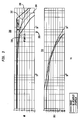
- the upsampler transfer function response 304 shows a great improvement over the non-upsampled transfer function response 302.
- the non-upsampled transfer function response 302 nearly touches the acceptable lower bound 310 near the 8 Hz frequency 306 where jack-hammering is observed, while at high frequencies the non-upsampled transfer function response 302 approaches the acceptable upper bound 308.
- the upsampler transfer function response 304 is between the acceptable lower bound 310 and acceptable upper bound 308 for all frequencies, and also shows a greatly improved roll-off at higher frequencies.
- the upsampler transfer function response 304 also shows improved phase response at low frequency.
- FIG. 4 diagrams of the upsampler instantaneous position response 400 and upsampler instantaneous current response 420 during a series of position commands 410 is presented.
- the non-upsampled position response 402 accelerates rapidly, but takes longer to reach the level of the final position command 410.
- the upsampled position response 404 accelerates more evenly along the desired response slope 406, and reaches the level of the final position command 410 before the non-upsampled position response 402.
- the non-upsampled current 412 swings back and forth as the actuator 104 is first accelerated, and then decelerated.
- the non-upsampled current 412 even clips, meaning that the maximum amount of current is being applied to the actuator 104.
- the upsampled current 414 illustrates a more smooth amount of power being applied to the actuator 104.
- the upsampler instantaneous position response 400 and upsampler instantaneous current response 420 illustrate the "go-stop" nature of the response without upsampler in comparison to the smooth response with the upsampler 202, 204, 206. Further, it is apparent that without the upsampler 202, 204, 206, the system requires a higher amount of instantaneous current to be available, meaning that the upsampler 202, 204, 206 can reduce the size of the power source necessary to power the actuators 104. Further, the non-upsampled current 412 shows the wasting of power when an opposite current is necessary to decelerate the actuator 104.
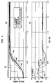
- This oscillation of the instantaneous current is illustrated in diagrams of the upsampler position response 500, upsampler current response 520, and upsampler pulse widths 540 in the diagrams of Figure 5 .
- the upsampler position response 500 in response to a series of position commands 410, the upsampled position response 404 reaches the level of the position commands whereas the non-upsampled position response 402 lags.
- the response curves illustrate the difference between the smooth upsampled current 414 response curves, and the oscillating non-upsampled current 412 response curves.
- the upsampler pulse widths 540 illustrates the corresponding pulse width modulation of the actuators 104.
- the methodology and systems described above are also applicable to integrating multirate control systems in general.
- the upsampler 202, 204, 206 or portions of the upsampler 202, 204, 206 can be incorporated into an industrial control system in manufacturing plants when two controllers in a manufacturing process utilize different sampling rates.
Landscapes
- Engineering & Computer Science (AREA)
- Physics & Mathematics (AREA)
- General Physics & Mathematics (AREA)
- Automation & Control Theory (AREA)
- Aviation & Aerospace Engineering (AREA)
- Feedback Control In General (AREA)
- Control Of Position Or Direction (AREA)
Description
- Many systems today, especially complex avionics systems, utilize pieces of mature technology that are combined with new technology to make the new system. It is generally more economical to use existing pieces of technology, rather than building something completely from the ground up. Reusing technology saves engineering resources that can be put to better use other parts on the system and often results in a product getting to market faster. Reusing technology saves test and verifcation time and resources, because a part that has already been qualified for a similar purpose generally does not need as many test cycles to verify.
- Feedback control systems are commonly used in closed-loop flight control systems and other industrial or commercial products. Some well known feedback control system include lead-lag compensators and PID, or proportional plus integral plus derivative, feedback control loops. Lead-lag compensators and PID feedback control loops are well known in the art for stabilizing physical systems.
- Flight control systems sometimes incorporate system components from different manufacturers that are combined to make a new system. System components that have somewhat different design specifications and parameters can exhibit undesirable behaviour when integrated together into a new system. For example, the sampling frequency for commands sent from a master computer to a closed-loop flight control system might be designed at a first frequency chosen so that the pilot or master computer has sufficient temporal granularity to accomplish a desired range of aerodynamic performance of the platform. However, the closed-loop flight control system may operate at a second much higher frequency that is designed to quickly adjust control surfaces during high speed flight with a much finer temporal granularity.
- When commands are sent by the master computer at the first frequency, the closed-loop flight control system immediately adjusts the flight control surfaces in accordance to the command from the master computer at the second frequency of the closed-loop flight control system. When the closed-loop flight control system is operating at a higher frequency, or faster sampling rate, than the master computer, the closed-loop flight control system will have to wait a number of cycles between commands. This results in periodic, start-and-stop behavior of the electro-mechanical closed-loop flight control system in response to the commands from the master computer. The start-and-stop behavior acts like a "jack-hammer" on the platform and triggers structural modes at the first frequency of the commands from the master computer, causing the flight control system to exhibit undesirable behaviour.
- One undesirable behavior that is triggered by the start-and-stop behavior is the creation of high current spikes that are sent to the flight control surfaces. When a command is received, the faster closed-loop flight control system immediately causes an actuation of a flight control surface, followed by the PID feedback loop attempting to stabilize the control surface to value presented in the command. This actuation by the closed-loop flight control system occurs at a high slew rate - the sampling rate of the closed-loop flight control system. This potentially results in full current commands during long slews, either with or without loads on the control surfaces.
- The current spikes are followed by valleys of relatively low current usage by the flight control surfaces. This periodic demand of high current spikes followed by valleys of low current demand is inefficient from a power perspective, because it requires bigger power systems to supply power for the current spikes and also requires heavier wiring between systems. These current spikes place strains on the flight control surfaces. For example, current spikes associated with typical commands being operated on by the closed-loop flight control system can generate maximum loads on the flight control surfaces. High loads decrease the lifespan of components, requiring more scheduled maintenance and reducing the number of missions between servicing.
- Another undesirable behavior resulting from the start-and-stop behavior is that lead-lag or PID feedback loop may not exhibit a desirable 40 dB/decade roll off past the specified bandwidth frequency of the closed-loop flight control system. This can lead to potential instability of the closed-loop flight control system. Attempts to attenuate the start-and-stop behavior generally result in increased phase changes that can create further instability in the system. For example, bi-quad filters on the command path can be used to smooth the command itself, but can cause unacceptable phase loss.
- "Digital redesign and multi-rate control for motion control - a general approach and application to hard disk drive servo system", by Y.Gu et al, discloses the digital redesign of continuous time controllers for motion control. Multi-rate digital control with a high order hold is utilized to better approximate the continuous time controller when the measurement sampling rate is relatively low. The proposed approach is illustrated for track following control of a hard disk drive (HDD) servo system. The HDD controller is first designed in the continuous time domain based on LQG/LTR method. It is redesigned as a single rate digital controller as well as multi-rate digital controllers with different holds.
- "Multirate controllers design by rate decomposition" by J.Salt et al discloses that in many industrial control applications the control action updating can be faster than the output measurement, leading to multirate (MR) controllers. The controller design is approached based on the characteristics of each available sampling rate. The controller is split into two parts acting at different sampling rates. By the lowest rate sub-controller the main points of the desired response are determined while the response envelope, approaching the continuous time response of the controlled system is completed by the action of the fast rate control part. Cancellation controllers, three-term controllers and PID controllers are designed using this approach and promising results are obtained.
- "Taking the mystery out of motion-control algorithms" by T.B. Bullock et al discloses that before digital calculators made slide rules an obsolete technology, most motion control systems were analog. The building blocks available to system designers in those days were proportional-gain amplifiers, integrators, differentiators, and a variety of active and passive filters. The algorithms that described them were basic differential equations, sometimes elevated to Laplace transforms. With the proliferation of inexpensive computers, the temptation to put digital tools to work in closed-loop motion control systems was great. Digital electronics could eliminate the drift that plagued analog controllers, and digital systems could handle many new algorithms and functions such as databases, self-tuners, and logical operators that were too cumbersome or impractical for analog systems.
- Presented is a system and method for integrating multirate systems using a combination of nonlinear and linear filtering. In an embodiment, a method of nonlinearly smoothing low frequency commands from an outer-loop to high frequency controls within an inner loop is presented. A nonlinear upsampler applies linear filtering to attenuate the commands past the specified bandwidth frequency, thus enabling the inner-loop controls to provide maximum resistance to external disturbances without sacrificing high frequency attenuation to commands. In a non-limiting example embodiment, an algorithm upsamples the commands from a lower sample rate master computer system and generates higher sample controls in a closed-loop control system for flight actuators. In embodiments, the system and method provides smooth, quick performance with 40 dB decade gain attenuation past the specified bandwidth frequency of the closed-loop control system and reduces phase loss at frequencies critical to flight control system stability margins.
- In an embodiment, the multirate system for controlling an actuator comprises an incremental command limiter for changing a command from a first control system into a limited incremental command for a second control system, a lead-lag filter for filtering the limited incremental command to attenuate high frequencies, and a feed forward path for reducing phase loss in rate output signal at low frequencies.
- In an embodiment, the upsampler comprises a means for a means for computing a difference between position signal from a first control system, a means for dividing the difference into an incremental position signal based on the ratio of sampling rates between the first control system and a second control system, and adding the incremental position signals to the position signal for each cycle at the sample rate of a second control system until the next position signal is received from the first control system.
- The features, functions, and advantages discussed can be achieved independently in various embodiments of the present invention or may be combined in yet other embodiments further details of which can be seen with reference to the following description and drawings.
- The accompanying figures depict various embodiments of the system and method for integrating multirate systems for electro-mechanical flight actuation using an integrated upsampler and filter. A brief description of each figure is provided below. Elements with the same reference number in each figure indicated identical or functionally similar elements. Additionally, the left-most digit(s) of a reference number indicate the drawing in which the reference number first appears.
-
Fig. 1 is a diagram of a flight control system in one embodiment of the system and method for integrating multirate systems for electro-mechanical flight actuation using an integrated upsampler and filter; -
Fig. 2a is a diagram of a simplified position/rate closed loop controller having an integrated upsampler and filter in one embodiment of the system and method for integrating multirate systems for electro-mechanical flight actuation using an integrated upsampler and filter; -
Fig. 2b is a diagram of a position/rate closed loop controller having an integrated upsampler and filter in one embodiment of the system and method for integrating multirate systems for electro-mechanical flight actuation using an integrated upsampler and filter; -
Fig. 3 is a graph illustrating the upsampler transfer function response and phase for position commands in one embodiment of the system and method for integrating multirate systems for electro-mechanical flight actuation using an integrated upsampler and filter; -
Fig. 4 is a graph illustrating the upsampler instantaneous current response corresponding to position commands for the closed-loop control system in one embodiment of the system and method for integrating multirate systems for electro-mechanical flight actuation using an integrated upsampler and filter; and, -
Fig. 5 is a graph illustrating a current response profile corresponding to a plurality of example position commands for the closed-loop control system in one embodiment of the system and method for integrating multirate systems for electro-mechanical flight actuation using an integrated upsampler and filter. - The following detailed description is merely illustrative in nature and is not intended to limit the embodiments of the invention or the application and uses of such embodiments. Furthermore, there is no intention to be bound by any expressed or implied theory presented in the preceding technical field, background, brief summary or the following detailed description.
- Referring now to
Figure 1 , an exemplaryflight control system 100 is presented. Theflight control system 100 comprises a vehicle 102, such as an aircraft, that has aflight control surface 104, such as an aileron, whose position is controlled by anactuator 106, such as an electromechanical actuator. Theactuator 106 or theflight control surface 104 are in communication with a position/rate feedback sensor 108, for example a rotary sensor that is connected to theactuator 106. The position/rate feedback sensor 108 allows theflight control system 100 to know the precise position, angular rotation, and rate of theflight control surface 104. Amaster computer 110 sends a command signal 112 instructing the flight actuator controller orFAC 114 to reposition theflight control surface 104 to a particular position or angular rotation. TheFAC 114, which is usually located in theavionics bay 116, sends anactuation signal 118 to theactuator 106 to move theflight control surface 104. In embodiments, theactuation signal 118 is a current or a signal to another device to supply current into theactuator 106 to actuate theflight control surface 104. Afeedback signal 120 returns from the position/rate feedback sensor 108 to theFAC 114. - In a
flight control system 100 it is possible to have amaster computer 110 that is issuing flight related commands at a first sample rate or frequency and a flight actuation control system orFAC 114 that operates at a second faster sample rate or higher frequency. For example, the sampling frequency for commands sent from amaster computer 110 to the flight control system, orFAC 114, might be designed at a first frequency chosen so that the pilot andmaster computer 110 has sufficient temporal granularity to accomplish a desired range of aerodynamic performance of the platform, or vehicle 102. However, theFAC 114 may operate at a second much higher frequency that is designed to quickly adjustcontrol surfaces 104 during high speed flight with a much finer temporal granularity. - Because of the differences in the sample rates, or frequencies, between the two system components, the
master computer 110 and theFAC 114, an undesirable behaviour can result. For example, if themaster computer 110 operates at 50 Hz, then 50 times per second themaster computer 110 would send command signals 112 to update theactuator 104 position to the flight actuator controller orFAC 114. However, if theFAC 114 operates at 2000 Hz, then theFAC 114 operates theflight actuators 104 at 2000 Hz. Because of this difference between the sample rates, or frequencies, theFAC 114 sees the command signals 112 as a series of stair-step position commands from themaster computer 110 that are spaced 40 cycles apart. That is, after theFAC 114 sees a first command signal 112, theFAC 114 does not see a change in the position of the control surface via a change in the command signal 112 for another 40 cycles (2000 Hz/50 Hz.) When theFAC 114 sees the next command signal 112 with a change, it immediately changes the position of theflight control surface 104, and then waits another 40 cycles for the next command signal 112. - The maximum increment between 2000 Hz samples should be RateLimit/2000. But, it is using RateLimit/50. Therefore, the response of the
FAC 114 is to a rate that appears 40 times greater than desired by themaster computer 110. This high rate command during the first .006 seconds of the 50 Hz frame causes a jerking and full current command. The response of theactuator 106 is a jerking, then as the position rate error becomes in the stabilizing direction, the actuation torque is arresting. Therefore, a jerk forward, slow down, jerk forward, slow down motion occurs at 50 Hz. This effectively causes a 50 Hz jack-hammering from an 8 Hz bandwidth actuation system. - Before the upsampler, many methods were attempted to attenuate the jack-hammering, but they resulted in increased phase at the 1-2 hz frequencies, where the
master computer 110 stability margins are extremely critical. For instance, bi-quad filters on the command path smoothed the "jerk," but caused unacceptable phase loss at 1 to 2 hz that could not be tolerated by themaster computer 110. Changing theFAC 114 commanding from position commands at 50 Hz to rate commands at 50 hz, would eliminate the jack-hammering, but themaster computer 110 would need to close the position loop, but the cost of overhauling the completed master computer software would be too costly, require years of rework and certification, and would have less robustness than theFAC 114 closing the position loops. Therefore, a method that eliminated the jack-hammering, reduced phase loss at low frequencies, and preserved the quick response under load was needed. Theupsampler - Referring now to
Figure 2a , a simplified diagram of a position/rate closed-loop controller 200 having anintegrated upsampler upsampler incremental command limiter 202, the lead-lag on limitedincremental command 204, and the feed-forward path 206. - The position/rate closed-
loop controller 200 receives a command signal 112 from another controller, for example aposition command 212 from themaster computer 110. Theincremental command limiter 202 interpolates theposition command 212 into the sampling rate of the position/rate closed-loop controller 200 and feeds a limited incremental command to the lead-lag on limitedincremental command 204. - The lead-
lag filter 204 shapes the limitedincremental command 222 in order to attenuate the high frequency components in the position commands 212 (e.g., greater than specified bandwidth of the system.) The feed-forward 206 produces a feedforward rate command 226 that reduces phase loss at low frequencies (e.g., less than 2 Hz). Together, the lead-lag filter 204 and feed-forward 206 perform lead-lag compensation for the control loop of the position/rate closed-loop controller 200 and are therefore sometimes called a lead-lag compensator. Theupsampler state 201 feeds the current state back to a differentiator, orsummer 205, that is used, in part, to limit the limitedincremental command 222 to a maximum allowable command. And asummer 207 in the lead-lag on limitedincremental command 204 produces the filtered incremental command signal. A differentiator, orsummer 209 compares the filteredincremental command signal 225 to theposition feedback signal 228 to derive aposition error signal 227 which is processed and amplified byamplifier 213 to produce therate command 232. Asummer 211 combines therate command 232, with the feed forwardrate command 226 and therate feedback 230 to produce therate output signal 205. Apower amplifier 215 produces a pulse width modulated current for actuating the actuator 106 from therate output signal 205. One or more elliptical filters, biquad filters, or low pass filters 224 help to attenuate noise from position/rate signal(s) from the position/rate feedback sensor 108. - Referring now to
Figure 2b , a more detailed diagram of a position/rate closed-loop controller 200 is presented to describe additional features. Theincremental command limiter 202 differences theupsampler state 214 from the last receivedcommand 212 from themaster computer 110 to produce adifference 208 whose value is an unpolarized absolute value. Thisdifference 208 is limited to an increment no larger than the intendedrate command 212 from themaster computer 110. For small rates, abias 216 shown in one non-limiting example as .0001 units, is added to prevent sluggish motion. Aninterpolator 220 divides thedifference 208 into smaller incremental changes according to the ratio of the sample rate of the master computer 110 (50 Hz) and the FAC 114 (2000 Hz), shown here as 50/2000 or .025 units. Although the system is illustrated having aFAC 114 whose sample rate is an integer multiple of thecomputer 110, it should be noted that other ratios can be used. In embodiments, ratios between 1 and the actual ratio between the two system can be used. In embodiments, linear interpolation, logarithmic interpolation, and other non-linear interpolation schemes could be utilized to create the incremental changes without deviating from this disclosure. - For each cycle of the
FAC 114, theincremental command 222 has added to it thedifference 208 multiplied by .025, so that after 40 cycles theincremental command 222 has a position value equal to thecommand 212 sent by the master computer. A delta upper yield, orDUY 210, provides a reference value used by anunpolarized clipper 213 to clip theincremental command 222 if necessary to prevent theincremental command 222 from exceeding the maximum allowable position change. Arepolarizer 221 restores the positive or negative polarization of the incremental command and in combination with theunpolarized clipper 213 produces the limitedincremental command 223. - In embodiments, the
amplifier 203 comprises ahysteresis function 215 to prevent least significant bit (LSB) chatter from being introduced into the rate command. In embodiments, aclipper 217 in either theamplifier 203 orpower amplifier 215 prevents rate commands from exceeding a amplitudes that may create too much stress on theactuator 106 or other structures of the vehicle 102. In embodiments, thepower amplifier 215 comprises a rate to pulse-width modulation converter 219. - Referring now to
Figure 3 , a diagram of thetransfer function response 300 from position command to position response is illustrated. The upsamplertransfer function response 304 shows a great improvement over the non-upsampledtransfer function response 302. The non-upsampledtransfer function response 302 nearly touches the acceptable lower bound 310 near the 8Hz frequency 306 where jack-hammering is observed, while at high frequencies the non-upsampledtransfer function response 302 approaches the acceptable upper bound 308. The upsamplertransfer function response 304 is between the acceptable lower bound 310 and acceptable upper bound 308 for all frequencies, and also shows a greatly improved roll-off at higher frequencies. In the phase diagram 320, the upsamplertransfer function response 304 also shows improved phase response at low frequency. - Referring now to
Figure 4 , diagrams of the upsamplerinstantaneous position response 400 and upsampler instantaneouscurrent response 420 during a series of position commands 410 is presented. As illustrated, during a series of position commands 410, thenon-upsampled position response 402 accelerates rapidly, but takes longer to reach the level of thefinal position command 410. Theupsampled position response 404 accelerates more evenly along the desiredresponse slope 406, and reaches the level of thefinal position command 410 before thenon-upsampled position response 402. - As illustrated, during the series of position commands 410, the non-upsampled current 412 swings back and forth as the
actuator 104 is first accelerated, and then decelerated. - At one point, the non-upsampled current 412 even clips, meaning that the maximum amount of current is being applied to the
actuator 104. In comparison, the upsampled current 414 illustrates a more smooth amount of power being applied to theactuator 104. - The upsampler
instantaneous position response 400 and upsampler instantaneouscurrent response 420 illustrate the "go-stop" nature of the response without upsampler in comparison to the smooth response with theupsampler upsampler upsampler actuators 104. Further, the non-upsampled current 412 shows the wasting of power when an opposite current is necessary to decelerate theactuator 104. - This oscillation of the instantaneous current is illustrated in diagrams of the
upsampler position response 500, upsamplercurrent response 520, andupsampler pulse widths 540 in the diagrams ofFigure 5 . Similar toFigure 4 , in theupsampler position response 500, in response to a series of position commands 410, theupsampled position response 404 reaches the level of the position commands whereas thenon-upsampled position response 402 lags. In the upsamplercurrent response 520, the response curves illustrate the difference between the smooth upsampled current 414 response curves, and the oscillating non-upsampled current 412 response curves. Theupsampler pulse widths 540 illustrates the corresponding pulse width modulation of theactuators 104. - Although some of the embodiments of the disclosure are directed to
flight control systems 100, the methodology and systems described above are also applicable to integrating multirate control systems in general. For example, theupsampler upsampler - The embodiments of the invention shown in the drawings and described above are exemplary of numerous embodiments that may be made within the scope of the appended claims. It is contemplated that numerous other configurations of the system and method for integrating multirate systems using an integrated upsampler and filter may be created taking advantage of the disclosed approach. It is the applicant's intention that the scope of the patent issuing herefrom will be limited only by the scope of the appended claims.
Claims (17)
- A multirate system (200) for controlling an actuator (106), comprising:an incremental command limiter (202) configured to output a limited incremental command (222);a lead-lag filter (204) configured to filter said limited incremental command to attenuate frequencies greater than the bandwidth of the multirate system to produce a shaped limited incremental command;a position error signal (227) derived from the shaped limited incremental command and from a position feedback signal (228) from the actuator;an amplifier (213) configured to produce a rate command (232) from said position error signal;a feed forward path (206) configured to produce a feed forward rate command (226) derived from said shaped limited incremental command; and,a summer (211) configured to produce a rate output signal (205) for controlling the actuator from said rate command and said feed forward rate command;wherein said multirate system comprises a first control system (110) and a second control system (114), and wherein said incremental command limiter is configured to interpolate a position command (212) from said first control system to produce a limited incremental command of said second control system; and
wherein said first control system has a first sampling rate, and said second control system has a second sampling rate different than said first sampling rate. - The system (200) of claim 1, wherein said first control system (110) is configured to send said command (212) to said second control system (114) at said first sampling rate, and said second control system is configured to interpolate said command to produce said limited incremental command (222) at said second sampling rate.
- The system (200) of claim 1, wherein said second sampling rate is an integer multiple of said first sampling rate.
- The system (200) of claim 1, wherein said feed forward rate command (226) is configured to reduce phase errors in said rate output signal (205) at low frequencies.
- The system (200) of claim 1, further comprising:a rate error signal (230) from the actuator (106); andwherein said summer (211) is configured to produce said rate output signal (205) from said feed forward rate command (226), said rate command (232), and said rate error signal.
- The system (200) of claim 5, further comprising:a first low pass filter (224) configured to attenuate noise in said rate error signal (230) from the actuator (106); and,a second low pass filter (224) configured to attenuate noise in said position error signal (228) from the actuator.
- The system (200) of claim 1, further comprising:a second amplifier (215) configured to convert said output signal into a pulse width modulated current for actuating the actuator (106).
- A method for integrating multirate control systems, comprising:receiving a command position signal (212) at a first sampling rate;interpolating said command position signal to produce an incremental command position signal (222) at a second sampling rate;filtering said incremental command position signal to attenuate frequencies greater than the bandwidth of the control systems to produce a shaped incremental command position signal;processing and amplifying a position error signal (227) derived from said shaped incremental command position signal and from a position feedback signal (228) from an actuator (106) to produce a rate command (232);producing a feed forward rate command (226) derived from said shaped incremental command position signal to prevent phase loss at low frequencies; andsumming said rate command and said feed forward rate command to produce a rate output signal (205) for controlling the actuator (106).
- The method of claim 8, wherein said operation of filtering said incremental command position signal (222) and said operation of producing said feed forward rate command (226) is performed by a lead-lag compensator (204, 206).
- The method of claim 8, wherein said operation of interpolating comprises:computing a difference from said command position signal and a previous command position signal.dividing said difference into an increment according to a ratio between said first sampling rate and said second sampling rate;adding said increment to said previous command position signal to obtain said incremental position signal for a first cycle at said second sampling rate; andadding said increment to said incremental position signal for each subsequent cycle at said second sampling rate until a next command position signal is received.
- The method of claim 8, further comprising:receiving a rate error signal (230); andwherein said operation of summing comprises summing said rate command (232), said rate error signal, and a feed forward rate command (226) to produce the role output signal (205).
- The method of claim 11, further comprising:filtering said rate error signal (230) to attenuate noise in said rate error signal; andfiltering a position error signal (228) to attenuate noise in said position error signal.
- The method of claim 8, further comprising:converting said rate output signal (205) into a pulse width modulated current.
- The method of claim 13, further comprising:applying said pulse width modulated current to an actuator (106) associated with the multirate control system.
- An upsampler (202, 204, 206) for modifying commands between a plurality of control systems (110, 114), comprising:a means for computing a difference between a first command position signal (212) and a second command position signal from a first control system.a means for dividing said difference into an incremental command according to a ratio between a first sampling rate of said first control system, and said second sampling rate of a second control system;a means (202) for adding said incremental command to said first command position signal to obtain an incremental position signal (222) for a first cycle at said second sampling rate;a means (204) for filtering said incremental position signal to attenuate frequencies greater than the bandwidth of the control systems to produce a shaped incremental position signal;a means (206) for producing a feed forward rate command (226) derived from said shaped incremental position signal to prevent phase loss at low frequencies; anda means (211) for adding said incremental command to said incremental position signal for each subsequent cycle at said second sampling rate until a third command position signal is received.
- The upsampler (202, 204, 206) of claim 15, wherein said first control system (110) sends said first command position signal (212) to said second control system at said first sampling rate, and said second control system element interpolates said command into said incremental position signal (222) at said second sampling rate, and wherein said second sampling rate is an integer multiple of said first sampling rate.
- The upsampler (202, 204, 206) of claim 16, wherein the upsampler is integrated into a control loop of said second control system, and wherein said control loop of said second control system controls a physical device (106) using said incremental position signal.
Applications Claiming Priority (1)
| Application Number | Priority Date | Filing Date | Title |
|---|---|---|---|
| US12/892,853 US8653780B2 (en) | 2010-09-28 | 2010-09-28 | Integrated upsampler and filtering for multi-rate controller for electro-mechanical flight actuation system |
Publications (3)
| Publication Number | Publication Date |
|---|---|
| EP2434356A2 EP2434356A2 (en) | 2012-03-28 |
| EP2434356A3 EP2434356A3 (en) | 2014-11-19 |
| EP2434356B1 true EP2434356B1 (en) | 2016-08-31 |
Family
ID=44785314
Family Applications (1)
| Application Number | Title | Priority Date | Filing Date |
|---|---|---|---|
| EP11179824.5A Active EP2434356B1 (en) | 2010-09-28 | 2011-09-02 | Integrated upsampler and filtering for multi-rate control of an electro-mechanical actuator |
Country Status (5)
| Country | Link |
|---|---|
| US (2) | US8653780B2 (en) |
| EP (1) | EP2434356B1 (en) |
| JP (1) | JP5825953B2 (en) |
| CN (1) | CN102437834B (en) |
| ES (1) | ES2604671T3 (en) |
Families Citing this family (9)
| Publication number | Priority date | Publication date | Assignee | Title |
|---|---|---|---|---|
| US8478456B2 (en) * | 2011-08-08 | 2013-07-02 | Raytheon Company | Variable bandwidth control actuation methods and apparatus |
| US10401875B2 (en) | 2014-07-31 | 2019-09-03 | The Boeing Company | Electronic stopper in actuator control |
| US9791560B2 (en) * | 2014-08-13 | 2017-10-17 | Infineon Technologies Ag | Radar signal processor, radar system and method for monitoring a functional safety of a radar system |
| US9452822B2 (en) * | 2014-10-02 | 2016-09-27 | Honeywell International Inc. | Methods and apparatus for providing servo torque control with load compensation for pilot in the loop |
| US9645948B2 (en) * | 2015-01-16 | 2017-05-09 | Hamilton Sundstrand Corporation | Access key generation for computer-readable memory |
| US10447180B2 (en) | 2016-01-12 | 2019-10-15 | Hamilton Sundstrand Space Systems International, Inc. | Control of large electromechanical actuators |
| US11803168B2 (en) * | 2019-03-08 | 2023-10-31 | General Electric Company | Distributed control modules with cumulating command references |
| CN110083059B (en) * | 2019-04-01 | 2022-04-22 | 河海大学常州校区 | Discrete time sliding mode incomplete robot stabilization control method |
| US20220388672A1 (en) * | 2021-06-03 | 2022-12-08 | Bell Textron Inc. | Propulsion assembly |
Family Cites Families (10)
| Publication number | Priority date | Publication date | Assignee | Title |
|---|---|---|---|---|
| US5005089A (en) * | 1988-05-10 | 1991-04-02 | Quantum Corp. | High performance, high capacity micro-winchester disk drive |
| US6006637A (en) * | 1995-04-18 | 1999-12-28 | Kimberly-Clark Worldwide, Inc. | Servo driven watercutter |
| US6204823B1 (en) * | 1999-03-09 | 2001-03-20 | Harris Corporation | Low profile antenna positioner for adjusting elevation and azimuth |
| US6614615B1 (en) * | 2000-03-31 | 2003-09-02 | Western Digital Technologies, Inc. | Disk drive with adaptive control path that produces an adaptive control effort based on a characterized deviation between actual and modeled plant response |
| US6614618B1 (en) * | 2000-03-31 | 2003-09-02 | Western Digital Technologies, Inc. | Disk drive with feed-forward control path that receives a reference position signal to apply a feed-forward command effort at a rate greater than a servo sampling rate |
| US6636377B1 (en) * | 2000-06-30 | 2003-10-21 | Western Digital Technologies, Inc. | Method of tuning feed-forward control in a disk drive |
| US7317981B2 (en) * | 2004-11-19 | 2008-01-08 | Honeywell International, Inc. | Aircraft brake actuation system and method including anti-hysteresis control |
| JP5715324B2 (en) * | 2005-10-12 | 2015-05-07 | バン・ビエールフリエト, フィリップVan Biervliet, Filip | Flight simulator movement control method and flight simulator implementing such a method |
| CN100405011C (en) * | 2007-07-09 | 2008-07-23 | 北京信息工程学院 | Novel piezoelectric quartz horizontal attitude sensor |
| US8649885B2 (en) * | 2008-11-25 | 2014-02-11 | Nikon Corporation | Frequency selective iterative learning control system and method for controlling errors in stage movement |
-
2010
- 2010-09-28 US US12/892,853 patent/US8653780B2/en active Active
-
2011
- 2011-09-02 EP EP11179824.5A patent/EP2434356B1/en active Active
- 2011-09-02 ES ES11179824.5T patent/ES2604671T3/en active Active
- 2011-09-22 JP JP2011207315A patent/JP5825953B2/en active Active
- 2011-09-28 CN CN201110302955.9A patent/CN102437834B/en active Active
-
2014
- 2014-02-17 US US14/182,151 patent/US9405277B2/en active Active
Also Published As
| Publication number | Publication date |
|---|---|
| US9405277B2 (en) | 2016-08-02 |
| CN102437834B (en) | 2017-06-06 |
| ES2604671T3 (en) | 2017-03-08 |
| EP2434356A3 (en) | 2014-11-19 |
| JP2012075100A (en) | 2012-04-12 |
| US8653780B2 (en) | 2014-02-18 |
| US20120078446A1 (en) | 2012-03-29 |
| CN102437834A (en) | 2012-05-02 |
| US20160154384A1 (en) | 2016-06-02 |
| EP2434356A2 (en) | 2012-03-28 |
| JP5825953B2 (en) | 2015-12-02 |
Similar Documents
| Publication | Publication Date | Title |
|---|---|---|
| EP2434356B1 (en) | Integrated upsampler and filtering for multi-rate control of an electro-mechanical actuator | |
| Mehedi et al. | Two degrees of freedom fractional controller design: Application to the ball and beam system | |
| TWI504131B (en) | Motor control device | |
| US20170277150A1 (en) | Motor controller having function of reducing vibration | |
| Ziaei et al. | Design of a nonlinear adaptive controller for an electrohydraulic actuator | |
| Ibraheem et al. | An improved active disturbance rejection control for a differential drive mobile robot with mismatched disturbances and uncertainties | |
| JP7039176B2 (en) | Delay compensator filter design method, feedback control method using it, motor control device | |
| CN113157012B (en) | Method and system for controlling mechanical vibration | |
| KR102085047B1 (en) | Ervo motor control system | |
| Chen et al. | Robust optimal model matching control design for flexible manipulators | |
| Ansari et al. | Adaptive control of an aircraft with uncertain nonminimum-phase dynamics | |
| Duan et al. | Energy optimal control of an over-actuated hybrid feed drive under variable-frequency disturbances— with application to machining | |
| CN113315413B (en) | Design method of filter type second-order terminal discrete sliding mode controller of piezoelectric linear motor | |
| Kelly et al. | An interpolation strategy for scheduling dynamic compensators | |
| CN110879526B (en) | Fractional order controller and parameter setting method thereof | |
| Atsari et al. | Design of a Fractional Order PID Controller for Electric Hydraulic Actuator | |
| Receanu | Modeling and simulation of the nonlinear computed torque control in simulink/MATLAB for an industrial robot | |
| Banavar et al. | A loop transfer recovery approach to the control of an electro-hydraulic actuator | |
| RU2368932C1 (en) | Electrohydraulic direct control follow-up drive with adaptive properties | |
| US6870345B1 (en) | Servo loop PID compensator with embedded rate limit | |
| Yang et al. | A double-loop control structure for tracking control and disturbance attenuation | |
| Ahmad et al. | Analysis of IIR filter with NCTF-PI control for sway and trajectory motion of a DPTOC System | |
| EP0772803B1 (en) | Method and apparatus for phase compensation in a vehicle control system | |
| Cheng et al. | Design of robust tracking controllers using sliding mode technique | |
| Bruzzone et al. | Nondimensional Analysis of Fractional-Order PDD1/2 Control of Purely Inertial Systems |
Legal Events
| Date | Code | Title | Description |
|---|---|---|---|
| PUAI | Public reference made under article 153(3) epc to a published international application that has entered the european phase |
Free format text: ORIGINAL CODE: 0009012 |
|
| 17P | Request for examination filed |
Effective date: 20110902 |
|
| AK | Designated contracting states |
Kind code of ref document: A2 Designated state(s): AL AT BE BG CH CY CZ DE DK EE ES FI FR GB GR HR HU IE IS IT LI LT LU LV MC MK MT NL NO PL PT RO RS SE SI SK SM TR |
|
| AX | Request for extension of the european patent |
Extension state: BA ME |
|
| PUAL | Search report despatched |
Free format text: ORIGINAL CODE: 0009013 |
|
| AK | Designated contracting states |
Kind code of ref document: A3 Designated state(s): AL AT BE BG CH CY CZ DE DK EE ES FI FR GB GR HR HU IE IS IT LI LT LU LV MC MK MT NL NO PL PT RO RS SE SI SK SM TR |
|
| AX | Request for extension of the european patent |
Extension state: BA ME |
|
| RIC1 | Information provided on ipc code assigned before grant |
Ipc: G05B 11/01 20060101AFI20141013BHEP |
|
| GRAP | Despatch of communication of intention to grant a patent |
Free format text: ORIGINAL CODE: EPIDOSNIGR1 |
|
| INTG | Intention to grant announced |
Effective date: 20160315 |
|
| GRAS | Grant fee paid |
Free format text: ORIGINAL CODE: EPIDOSNIGR3 |
|
| GRAA | (expected) grant |
Free format text: ORIGINAL CODE: 0009210 |
|
| AK | Designated contracting states |
Kind code of ref document: B1 Designated state(s): AL AT BE BG CH CY CZ DE DK EE ES FI FR GB GR HR HU IE IS IT LI LT LU LV MC MK MT NL NO PL PT RO RS SE SI SK SM TR |
|
| REG | Reference to a national code |
Ref country code: CH Ref legal event code: EP Ref country code: GB Ref legal event code: FG4D |
|
| REG | Reference to a national code |
Ref country code: IE Ref legal event code: FG4D |
|
| REG | Reference to a national code |
Ref country code: FR Ref legal event code: PLFP Year of fee payment: 6 |
|
| REG | Reference to a national code |
Ref country code: DE Ref legal event code: R096 Ref document number: 602011029769 Country of ref document: DE |
|
| REG | Reference to a national code |
Ref country code: AT Ref legal event code: REF Ref document number: 825497 Country of ref document: AT Kind code of ref document: T Effective date: 20161015 |
|
| REG | Reference to a national code |
Ref country code: LT Ref legal event code: MG4D |
|
| REG | Reference to a national code |
Ref country code: NL Ref legal event code: MP Effective date: 20160831 |
|
| REG | Reference to a national code |
Ref country code: AT Ref legal event code: MK05 Ref document number: 825497 Country of ref document: AT Kind code of ref document: T Effective date: 20160831 |
|
| PG25 | Lapsed in a contracting state [announced via postgrant information from national office to epo] |
Ref country code: LT Free format text: LAPSE BECAUSE OF FAILURE TO SUBMIT A TRANSLATION OF THE DESCRIPTION OR TO PAY THE FEE WITHIN THE PRESCRIBED TIME-LIMIT Effective date: 20160831 Ref country code: HR Free format text: LAPSE BECAUSE OF FAILURE TO SUBMIT A TRANSLATION OF THE DESCRIPTION OR TO PAY THE FEE WITHIN THE PRESCRIBED TIME-LIMIT Effective date: 20160831 Ref country code: NO Free format text: LAPSE BECAUSE OF FAILURE TO SUBMIT A TRANSLATION OF THE DESCRIPTION OR TO PAY THE FEE WITHIN THE PRESCRIBED TIME-LIMIT Effective date: 20161130 Ref country code: RS Free format text: LAPSE BECAUSE OF FAILURE TO SUBMIT A TRANSLATION OF THE DESCRIPTION OR TO PAY THE FEE WITHIN THE PRESCRIBED TIME-LIMIT Effective date: 20160831 Ref country code: FI Free format text: LAPSE BECAUSE OF FAILURE TO SUBMIT A TRANSLATION OF THE DESCRIPTION OR TO PAY THE FEE WITHIN THE PRESCRIBED TIME-LIMIT Effective date: 20160831 |
|
| PG25 | Lapsed in a contracting state [announced via postgrant information from national office to epo] |
Ref country code: LV Free format text: LAPSE BECAUSE OF FAILURE TO SUBMIT A TRANSLATION OF THE DESCRIPTION OR TO PAY THE FEE WITHIN THE PRESCRIBED TIME-LIMIT Effective date: 20160831 Ref country code: NL Free format text: LAPSE BECAUSE OF FAILURE TO SUBMIT A TRANSLATION OF THE DESCRIPTION OR TO PAY THE FEE WITHIN THE PRESCRIBED TIME-LIMIT Effective date: 20160831 Ref country code: GR Free format text: LAPSE BECAUSE OF FAILURE TO SUBMIT A TRANSLATION OF THE DESCRIPTION OR TO PAY THE FEE WITHIN THE PRESCRIBED TIME-LIMIT Effective date: 20161201 Ref country code: BE Free format text: LAPSE BECAUSE OF NON-PAYMENT OF DUE FEES Effective date: 20160930 Ref country code: AT Free format text: LAPSE BECAUSE OF FAILURE TO SUBMIT A TRANSLATION OF THE DESCRIPTION OR TO PAY THE FEE WITHIN THE PRESCRIBED TIME-LIMIT Effective date: 20160831 Ref country code: SE Free format text: LAPSE BECAUSE OF FAILURE TO SUBMIT A TRANSLATION OF THE DESCRIPTION OR TO PAY THE FEE WITHIN THE PRESCRIBED TIME-LIMIT Effective date: 20160831 |
|
| REG | Reference to a national code |
Ref country code: ES Ref legal event code: FG2A Ref document number: 2604671 Country of ref document: ES Kind code of ref document: T3 Effective date: 20170308 |
|
| PG25 | Lapsed in a contracting state [announced via postgrant information from national office to epo] |
Ref country code: EE Free format text: LAPSE BECAUSE OF FAILURE TO SUBMIT A TRANSLATION OF THE DESCRIPTION OR TO PAY THE FEE WITHIN THE PRESCRIBED TIME-LIMIT Effective date: 20160831 Ref country code: RO Free format text: LAPSE BECAUSE OF FAILURE TO SUBMIT A TRANSLATION OF THE DESCRIPTION OR TO PAY THE FEE WITHIN THE PRESCRIBED TIME-LIMIT Effective date: 20160831 |
|
| REG | Reference to a national code |
Ref country code: CH Ref legal event code: PL |
|
| PG25 | Lapsed in a contracting state [announced via postgrant information from national office to epo] |
Ref country code: BE Free format text: LAPSE BECAUSE OF FAILURE TO SUBMIT A TRANSLATION OF THE DESCRIPTION OR TO PAY THE FEE WITHIN THE PRESCRIBED TIME-LIMIT Effective date: 20160831 Ref country code: SK Free format text: LAPSE BECAUSE OF FAILURE TO SUBMIT A TRANSLATION OF THE DESCRIPTION OR TO PAY THE FEE WITHIN THE PRESCRIBED TIME-LIMIT Effective date: 20160831 Ref country code: SM Free format text: LAPSE BECAUSE OF FAILURE TO SUBMIT A TRANSLATION OF THE DESCRIPTION OR TO PAY THE FEE WITHIN THE PRESCRIBED TIME-LIMIT Effective date: 20160831 Ref country code: DK Free format text: LAPSE BECAUSE OF FAILURE TO SUBMIT A TRANSLATION OF THE DESCRIPTION OR TO PAY THE FEE WITHIN THE PRESCRIBED TIME-LIMIT Effective date: 20160831 Ref country code: BG Free format text: LAPSE BECAUSE OF FAILURE TO SUBMIT A TRANSLATION OF THE DESCRIPTION OR TO PAY THE FEE WITHIN THE PRESCRIBED TIME-LIMIT Effective date: 20161130 Ref country code: CZ Free format text: LAPSE BECAUSE OF FAILURE TO SUBMIT A TRANSLATION OF THE DESCRIPTION OR TO PAY THE FEE WITHIN THE PRESCRIBED TIME-LIMIT Effective date: 20160831 Ref country code: PT Free format text: LAPSE BECAUSE OF FAILURE TO SUBMIT A TRANSLATION OF THE DESCRIPTION OR TO PAY THE FEE WITHIN THE PRESCRIBED TIME-LIMIT Effective date: 20170102 Ref country code: PL Free format text: LAPSE BECAUSE OF FAILURE TO SUBMIT A TRANSLATION OF THE DESCRIPTION OR TO PAY THE FEE WITHIN THE PRESCRIBED TIME-LIMIT Effective date: 20160831 |
|
| REG | Reference to a national code |
Ref country code: DE Ref legal event code: R097 Ref document number: 602011029769 Country of ref document: DE |
|
| REG | Reference to a national code |
Ref country code: IE Ref legal event code: MM4A |
|
| PLBE | No opposition filed within time limit |
Free format text: ORIGINAL CODE: 0009261 |
|
| STAA | Information on the status of an ep patent application or granted ep patent |
Free format text: STATUS: NO OPPOSITION FILED WITHIN TIME LIMIT |
|
| PG25 | Lapsed in a contracting state [announced via postgrant information from national office to epo] |
Ref country code: LI Free format text: LAPSE BECAUSE OF NON-PAYMENT OF DUE FEES Effective date: 20160930 Ref country code: CH Free format text: LAPSE BECAUSE OF NON-PAYMENT OF DUE FEES Effective date: 20160930 Ref country code: IE Free format text: LAPSE BECAUSE OF NON-PAYMENT OF DUE FEES Effective date: 20160902 |
|
| 26N | No opposition filed |
Effective date: 20170601 |
|
| PG25 | Lapsed in a contracting state [announced via postgrant information from national office to epo] |
Ref country code: SI Free format text: LAPSE BECAUSE OF FAILURE TO SUBMIT A TRANSLATION OF THE DESCRIPTION OR TO PAY THE FEE WITHIN THE PRESCRIBED TIME-LIMIT Effective date: 20160831 Ref country code: LU Free format text: LAPSE BECAUSE OF NON-PAYMENT OF DUE FEES Effective date: 20160902 |
|
| REG | Reference to a national code |
Ref country code: FR Ref legal event code: PLFP Year of fee payment: 7 |
|
| PG25 | Lapsed in a contracting state [announced via postgrant information from national office to epo] |
Ref country code: CY Free format text: LAPSE BECAUSE OF FAILURE TO SUBMIT A TRANSLATION OF THE DESCRIPTION OR TO PAY THE FEE WITHIN THE PRESCRIBED TIME-LIMIT Effective date: 20160831 Ref country code: HU Free format text: LAPSE BECAUSE OF FAILURE TO SUBMIT A TRANSLATION OF THE DESCRIPTION OR TO PAY THE FEE WITHIN THE PRESCRIBED TIME-LIMIT; INVALID AB INITIO Effective date: 20110902 |
|
| PG25 | Lapsed in a contracting state [announced via postgrant information from national office to epo] |
Ref country code: TR Free format text: LAPSE BECAUSE OF FAILURE TO SUBMIT A TRANSLATION OF THE DESCRIPTION OR TO PAY THE FEE WITHIN THE PRESCRIBED TIME-LIMIT Effective date: 20160831 Ref country code: MT Free format text: LAPSE BECAUSE OF NON-PAYMENT OF DUE FEES Effective date: 20160930 Ref country code: MK Free format text: LAPSE BECAUSE OF FAILURE TO SUBMIT A TRANSLATION OF THE DESCRIPTION OR TO PAY THE FEE WITHIN THE PRESCRIBED TIME-LIMIT Effective date: 20160831 Ref country code: IS Free format text: LAPSE BECAUSE OF FAILURE TO SUBMIT A TRANSLATION OF THE DESCRIPTION OR TO PAY THE FEE WITHIN THE PRESCRIBED TIME-LIMIT Effective date: 20160831 Ref country code: MC Free format text: LAPSE BECAUSE OF FAILURE TO SUBMIT A TRANSLATION OF THE DESCRIPTION OR TO PAY THE FEE WITHIN THE PRESCRIBED TIME-LIMIT Effective date: 20160831 |
|
| REG | Reference to a national code |
Ref country code: FR Ref legal event code: PLFP Year of fee payment: 8 |
|
| PG25 | Lapsed in a contracting state [announced via postgrant information from national office to epo] |
Ref country code: AL Free format text: LAPSE BECAUSE OF FAILURE TO SUBMIT A TRANSLATION OF THE DESCRIPTION OR TO PAY THE FEE WITHIN THE PRESCRIBED TIME-LIMIT Effective date: 20160831 |
|
| REG | Reference to a national code |
Ref country code: DE Ref legal event code: R082 Ref document number: 602011029769 Country of ref document: DE Representative=s name: KILBURN & STRODE LLP, NL |
|
| P01 | Opt-out of the competence of the unified patent court (upc) registered |
Effective date: 20230516 |
|
| PGFP | Annual fee paid to national office [announced via postgrant information from national office to epo] |
Ref country code: IT Payment date: 20230921 Year of fee payment: 13 Ref country code: GB Payment date: 20230927 Year of fee payment: 13 |
|
| PGFP | Annual fee paid to national office [announced via postgrant information from national office to epo] |
Ref country code: FR Payment date: 20230925 Year of fee payment: 13 Ref country code: DE Payment date: 20230927 Year of fee payment: 13 |
|
| PGFP | Annual fee paid to national office [announced via postgrant information from national office to epo] |
Ref country code: ES Payment date: 20231002 Year of fee payment: 13 |