EP2434348A2 - Image forming system and image forming apparatus - Google Patents
Image forming system and image forming apparatus Download PDFInfo
- Publication number
- EP2434348A2 EP2434348A2 EP11180839A EP11180839A EP2434348A2 EP 2434348 A2 EP2434348 A2 EP 2434348A2 EP 11180839 A EP11180839 A EP 11180839A EP 11180839 A EP11180839 A EP 11180839A EP 2434348 A2 EP2434348 A2 EP 2434348A2
- Authority
- EP
- European Patent Office
- Prior art keywords
- image
- image forming
- specific information
- forming apparatus
- mutual information
- Prior art date
- Legal status (The legal status is an assumption and is not a legal conclusion. Google has not performed a legal analysis and makes no representation as to the accuracy of the status listed.)
- Withdrawn
Links
Images




Classifications
-
- G—PHYSICS
- G03—PHOTOGRAPHY; CINEMATOGRAPHY; ANALOGOUS TECHNIQUES USING WAVES OTHER THAN OPTICAL WAVES; ELECTROGRAPHY; HOLOGRAPHY
- G03G—ELECTROGRAPHY; ELECTROPHOTOGRAPHY; MAGNETOGRAPHY
- G03G15/00—Apparatus for electrographic processes using a charge pattern
- G03G15/50—Machine control of apparatus for electrographic processes using a charge pattern, e.g. regulating differents parts of the machine, multimode copiers, microprocessor control
- G03G15/5016—User-machine interface; Display panels; Control console
-
- G—PHYSICS
- G03—PHOTOGRAPHY; CINEMATOGRAPHY; ANALOGOUS TECHNIQUES USING WAVES OTHER THAN OPTICAL WAVES; ELECTROGRAPHY; HOLOGRAPHY
- G03G—ELECTROGRAPHY; ELECTROPHOTOGRAPHY; MAGNETOGRAPHY
- G03G15/00—Apparatus for electrographic processes using a charge pattern
- G03G15/50—Machine control of apparatus for electrographic processes using a charge pattern, e.g. regulating differents parts of the machine, multimode copiers, microprocessor control
- G03G15/5016—User-machine interface; Display panels; Control console
- G03G15/502—User-machine interface; Display panels; Control console relating to the structure of the control menu, e.g. pop-up menus, help screens
-
- G—PHYSICS
- G03—PHOTOGRAPHY; CINEMATOGRAPHY; ANALOGOUS TECHNIQUES USING WAVES OTHER THAN OPTICAL WAVES; ELECTROGRAPHY; HOLOGRAPHY
- G03G—ELECTROGRAPHY; ELECTROPHOTOGRAPHY; MAGNETOGRAPHY
- G03G2215/00—Apparatus for electrophotographic processes
- G03G2215/00016—Special arrangement of entire apparatus
- G03G2215/00021—Plural substantially independent image forming units in cooperation, e.g. for duplex, colour or high-speed simplex
Definitions
- the present invention relates to an image forming system in which a plurality of image forming apparatuses are connected serially so that the image forming apparatuses share image forming by being assigned to an obverse or reverse side of a recording sheet or any of areas on the recording sheet, and the image forming apparatus used in the image forming system.
- an image forming system having a plurality of image forming apparatuses connected serially, wherein a recording sheet on which an image is formed by a first image forming apparatus in an area is subsequently inputted to a second image forming apparatus and the second image forming apparatus forms an image in another area on the recording sheet
- Patent Document 1 Japanese Patent Publication Open to Public Inspection No. 2006-340259
- Patent Document 2 Japanese Patent Publication Open to Public Inspection No. H11-313181
- the present invention has one aspect to solve the above problems and an object of the present invention is to provide an image forming system, having a plurality of image forming apparatuses connected serially which enables to share image forming by being assigned to an obverse and a reverse side of a recording sheet or any of area on the recording sheet, wherein mutual information of the entire image forming system and specific information of each apparatus can be easily verified.
- the present invention has another aspect to solve the above problems and an object of the present invention is to provide an image forming apparatus capable of verifying the mutual information of the entire image forming system and the specific information of each image forming apparatus in a state that a plurality of the image forming apparatuses are connected serially so as to enable sharing of image forming by being assigned to the obverse and the reverse side of the recording sheet or to any of the areas on the recording sheet.
- FIGs. 1 to 3 as an embodiment of the present invention, there is described an image forming system having an image forming apparatus 100 and a image forming apparatus 300 connected serially, wherein the apparatuses are assigned to an obverse side or a reverse side or any of areas on a recording sheet so as to enable sharing of image forming.
- the tow image forming apparatuses 100 an 200 serially connected there is disclosed a state where the tow image forming apparatuses 100 an 200 serially connected, however, three or more image apparatuses can be connected.
- the image forming system conducts image forming in a way that the image forming apparatuses 100 and 300 are connected serially along the flow of the recording sheet as Fig. 2 and 3 show and in the image forming apparatus 100 at the anterior stage, an image is formed in a portion of an area on the recording sheet then the recording sheet is inputted to the image forming apparatus 300 in the posterior stage and the image forming apparatus 300 in the posterior state forms an image in other portion of the area on the above recording sheet.
- the two image forming apparatuses 100 and 300 can form images on the obverse and the reverse sides of the recording sheets respectively, thus a high speed output is possible.
- the image forming apparatus 100 at the anterior stage forms the image on the obverse side of the recording sheet in advance, then the sheet is turned over via the intermediate processing apparatus 200, thereafter the image forming apparatus 300 at the second stage forms another image on the reverse side of the recording sheet, thereby the recording sheet is outputted face-down where the image on the obverse side is on the downside.
- Fig. 3 (a) shows, the image forming apparatus 100 at the anterior stage forms the image on the obverse side of the recording sheet in advance, then the sheet is turned over via the intermediate processing apparatus 200, thereafter the image forming apparatus 300 at the second stage forms another image on the reverse side of the recording sheet, thereby the recording sheet is outputted face-down where the image on the obverse side is on the downside.
- Fig. 3 (a) shows, the image forming apparatus 100 at the anterior stage forms the image
- the image forming apparatus 100 at the anterior stage forms the image on the reverse side of the recording sheet in advance, then the sheet is turned over via the intermediate processing apparatus 200, thereafter the image forming apparatus 300 at the posterior stage forms another image on the obverse side of the recording sheet, thereby the recording sheet is outputted face-up where the image on the obverse side is on the upside.
- the image on a first side which is an anterior image in a page sequence is called as an obverse image and the image on a second side which is a posterior image in the page sequence is called as a reverse image.
- the image forming apparatuses 100 and 300 can be assigned to forming of images having different colors such as ordinary color and special color in the same side of the recording sheet. Further, the image forming apparatuses 100 and 300 can be assigned to forming of images having different graduation such as a picture (graduation image) and a text (monochrome).
- the sheet feeding apparatus 50 is configured with a control section 51 to control each section of the sheet feeding apparatus 50, a communication section 52 to communicate with the image forming apparatus 100 representing a destination of sheet feeding, and a sheet feeding section 55 to feed the stored sheets at a predetermined timing requested by the image forming apparatus 100.
- the control section 51 can be omitted, in case the sheet feeding section 55 is directly operated by control from the image forming apparatus 100 to be described later.
- the image forming apparatus 100 represent a master (master machine) having an initiative and the image forming apparatus 300 represents a slave (slave machine) to serve a subsidiary function will be described, however the above relation can be reversed.
- functions of the master and the slave are assigned, though the image forming system is configured by combining stand-alone apparatuses which are basically the same type.
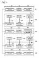
- the image forming apparatus 100 is configured with a control section 101 to control each section in the image forming apparatus 140 as well as to control an entire system representing the image forming system, a communication section 102 to communicate with other apparatuses in connection, an operation display section 105 to conduct input operation by a user and to display a status of the image forming apparatus 100, a memory section 130 to store image data when forming image and various items of data, an image processing section 140 to execute various image processes necessary for image forming and an image forming section 150 to execute image forming based on image forming commands and the image data.
- a control section 101 to control each section in the image forming apparatus 140 as well as to control an entire system representing the image forming system
- a communication section 102 to communicate with other apparatuses in connection
- an operation display section 105 to conduct input operation by a user and to display a status of the image forming apparatus 100
- a memory section 130 to store image data when forming image and various items of data
- an image processing section 140 to execute various image processes necessary for
- control section 101 is configured with an image control section 1011 which controls so as to selectively display a monolithic image representing the specific information or a mixed image representing combination of the specific information and the mutual information, as for the specific information in each image forming apparatus and the mutual information, in the image forming system, a mutual information image creation section 1012 to create a mutual information image based on the mutual information , a specific information image created section 1013 to create own apparatus specific information image based on the specific information of the image forming apparatus 100 (own apparatus) and a specific
- information image acquiring section 1015 to acquire anther apparatus specific information image based on the specific information of the image forming apparatus 300 (another apparatus).
- information related to each apparatus represents the specific information and the same mutual information for entire the image forming system, for example, information with respect to a job represents the mutual information.
- the operation display section 105 configures a display section to selectively display a monolithic image having only the specific information or the mixed image having the specific information and the mutual information.
- the operation display section 105 configures an operation section to notify the screen operation information to the control section 101 in case the operator conducts screen operation with respect to the image being displayed and to notify key codes to the control section 101 in case hardware keys (not illustrated) such as numerical keys and a copying button are operated.
- the intermediate processing apparatus 200 is configured with a communication section 202 to make the control section 210 to control each section in the intermediate processing apparatus 200 communicate with the image forming apparatuses 100 and 300 representing counter parts of processes, and an intermediate processing section 205 to conduct intermediate processing such as inversion of the recording sheet on which an image has been formed via the image forming apparatus 100 in the anterior state, so as to enable a suitable state that another image is formed on the reverse side of the recording sheet via the image forming apparatus 300 at the posterior stage.
- the control section 201 can be omitted.
- the image forming apparatus 300 is configured with a control section 301 to control each section in the image forming apparatus 300, a communication section 302 to communicate with other apparatuses connected, an operation display section 305 to conduct input operation by the user and display a status of the image forming apparatus 300, a memory section 330 to store image data when forming an image and various kinds of data, an image forming section 340 to execute various kids of image processing necessary for image forming, and the image forming section 350 to execute image forming based on the image forming command and the image data.
- control section 301 is configured with an image control section 3011 which controls to selectively display the monolithic image representing the specific information or the mixed image representing combination of the specific information and the mutual information, as for the specific information on individual image forming apparatuses and the mutual information on the image forming system, a mutual information image acquiring section 3012 to acquire the mutual information image based on the mutual information, a specific information image created section 3013 to create the own apparatus specific information image based on the specific information of the image forming apparatus 300 (own apparatus).
- image control section 3011 which controls to selectively display the monolithic image representing the specific information or the mixed image representing combination of the specific information and the mutual information, as for the specific information on individual image forming apparatuses and the mutual information on the image forming system
- a mutual information image acquiring section 3012 to acquire the mutual information image based on the mutual information
- a specific information image created section 3013 to create the own apparatus specific information image based on the specific information of the image forming apparatus 300 (own apparatus).
- the operation display section 305 configures a display section to selectively display a monolithic image having only the specific information or the mixed image having the specific information and the mutual information via display control of the image control section 3011.
- the operation display section 305 configures a control section to notify the screen operation information to the control section 301 in case the operator conducts screen operation with respect to the image being displayed and to notify key codes to the control section 301 in case hardware keys (not illustrated) such as numerical keys and a copying button are operated.
- the post-processing apparatus 400 is configured with a control section 401 to control each section in the post-processing apparatus 400, a communication section 402 to communicate with each apparatus, and a post-processing section 405 to apply various kinds of processes (punching process, stapling process and binding process) onto the recording sheet on which the image is formed by the image forming apparatuses 100 and 300 in accordance with control of the control section 401.
- the control section 401 can be omitted.
- a control flow chart of the image forming apparatus 100 via the control section 101 and a flow chart of the image forming apparatus 300 via the control section 301 are shown side by side.
- the display screen G1 to be displayed on the operation display section 105 and the operation display section 305 is configured as shown in Fig. 6 .
- tabs such as "copy”, “Scan”, “store”, job administration” and "machine condition” are allocated.
- corresponding screen operation information is created from the control sections 105 and 305, and corresponding display screens are created and displayed by the image control sections 1011 and 3011 which have received the above screen operation information.
- the control section 101 checks whether the specific information image is necessary in accordance with selection of the tab on the display screen in the operation display section 105 (Step S101 in Fig. 5 ) and if the specific information image is necessary (YES in step S 101 in Fig. 5 ), the specific information image creation section 1013 creates the own apparatus specific information image (hereinafter simply called specific information image as well) based on the specific information of the image forming apparatus 100 (own apparatus).
- specific information image hereinafter simply called specific information image as well
- the mutual information image creation section 1012 creates the mutual information image based on the mutual information of entire image forming system.
- any one of Steps S101 to S102 and S103 can be carried out in advance or can be carried out parallel.
- the control section 301 verifies whether the specific information image is necessary or not in conjunction with selection of the tab of the display screen in the operation display section 305 (Step 5201 in Fig. 5 ), and if the specific information image is necessary (YES in Step S201 in Fig. 5 ), the specific information image creation section 3013 creates the own apparatus specific information image based on the specific information of the image forming apparatus 300 (own apparatus)(Step S202 in Fig. 5 ).
- control section 301 verifies whether the mutual information image is necessary or not in conjunction with the display screen in the operation display section 305 (Step S203 in Fig. 5 ), and if the mutual information image is necessary (YES in Step S203 in Fig. 5 ) the mutual information acquiring section 3012 requests the mutual information image to the mutual information image creation section 1012(Step S204 in Fig. 5 ).
- the mutual information image creation section 1012 converts the created mutual information image into an image format such as jpeg and sends it to the mutual information image acquiring section 3012 (Step S105 in Fig. 5 ).
- the image control section 1011 draws the mutual information image created by the mutual information image creation section 1012 and the specific information image created by the specific information image creation section 1013 on a VRAM and displays on the operation display section 105 (Step S 106 in Fig. 5 ) in accordance with selection of the tab in the display screen.
- the VRAM the image memory of the image processing section 104 can be used, or the image control section 1011 can be provided with an exclusive memory (unillustrated).
- a necessary portion of the mutual information image acquired by the mutual information image acquiring section 3012 (Step S205 in Fig. 5 ) and the specific information image created by the specific information image creation section 3013 (Step S202 in Fig. 5 ) are combined by the image control section 3011 on the VRAM (Step S206 in Fig. 5 ) in accordance with selection of the tab in the display screen on the operation display section 305 and displayed on the operation display section 305 (Step S207 in Fig. 5 ).
- the VRAM of the image control section 3011 is the same as the VRAM of the image control section 1011. Namely, the specific information image crated by the specific information image creation section 3013 and a necessary portion of the mutual information image acquired by the mutual information image acquiring section 3012 are combined and drawn by the image control section 3011.
- the specific information image created by the specific information image creation section 3013 is drawn by the image control section 3011 on the VRAM (Step S206 in Fig. 5 ) and displayed on the operation display section 305 (Step S207 in Fig. 5 ).
- the mixed image and the monolithic image will be described with reference to tangible display screens displayed on the operation display sections 105 and the 305.
- a display screen G1 by selecting the "copy” tab a1 in Fig. 6 , "periodical check” a2 in Fig. 6 ,” image quality adjusting” a3 in Fig. 6 , and “sheet setting” a4 in Fig. 6 are specific information images created from the specific information of each image forming apparatus, and other portions are mutual information images which are mutual for the image forming system.
- the display screen G1 is a mixed image.
- the specific information image created by the specific information image creation section 1013 is drawn by the image control section 1011 on the VRAM and displayed on the operation display section 105. Also, on the image forming apparatus 300 side, the specific information image created by the specific information image creation section 3013 is drawn by the image control section 3011 on the VRAM and displayed on the operation control section 305.
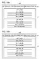
- the operation display section 105 on the image forming apparatus 100 side displays a display screen G5A in Fig. 10a and the control section 305 on the image forming apparatus 300 side displays a display screen G5B in Fig. 10b .
- the mutual information image and the specific information image are combined and displayed by dividing one screen largely.
- a job status is the mutual information image and da1 in the Fig. 10a and da1 in Fig.10b are the same.
- a tray status is the specific information image and da2 in Fig.10a is the specific information image of the image forming apparatus 100 created by the specific information image creation section 1013.
- the symbol db2 in Fig. 10b is the specific information image of the image forming apparatus 300 created by the specific information image creation section 3013.
- Fig. 11 shows a display screen showing a state where jamming occurs on the image forming apparatus 300 side while a job is executed in case the "job administration" tab shown by Fig. 10 is selected.
- a popup image db3 in Fig. 11b indicating occurrence of jam is displayed as an additional specific information image in addition to the conventional mutual information image and the specific information image.
- the above additional specific information image is created by the specific information image creation section 1013. In the event having higher priority or urgency it is preferred that the additional specific information image appropriately appears.
- the mutual information of the image forming system and the specific information of each apparatus can be easily verified in a state where a plurality of image forming apparatuses are connected serially so as to enable image forming by assigning the image forming apparatuses to the obverse and the reverse side of the recording sheet or to any of areas on one side of the recording sheet.
- a display screen to show the status of the jam occurrence in a condition where "job administration" tab shown in Fig. 11 is selected an example that only the operation display section 105 side displays is indicated in Fig. 12 .
- selection tabs such as “anterior stage” and “posterior stage” are provided on an upper section in the screen to select either the image forming apparatus 100 or the image forming apparatus 300 to display the display screen.
- a display screen for the image forming apparatus 100 which is equivalent to Fig.11 a is displayed on the operation display section 105 as Fig. 12a shows.
- a display screen for the image forming apparatus 300 having a popup screen which is equivalent to Fig. 11b , is displayed on the operation display section 105 as Fig. 12b shows.
- a flow chart to conduct the display in Fig.12 is shown in Fig. 13 .
- the specific information image acquiring section 1015 in the control section 101 judges existence of the specific information image of the image forming apparatus 300 (other apparatus) (Step S111 in Fig.13 ), and if the specific information image of the image forming apparatus 300 (other apparatus) exists (YES in Step S111 in Fig.13 ), the control section 101 requests the specific information image of the image forming apparatus 300 to the specific information image creation section 3013 (Step S212 in Fig. 13 ).
- the specific information image creation section 3013 converts the created specific information image (Step S211 in Fig. 13 ) into the image format such as jpeg and transmits to the specific information image acquiring section 1015 (Step S212 in Fig. 13 ).
- a necessary portion of the specific image of the other apparatus acquired by the specific information image acquiring section 1015 (Step S 113 in Fig. 13 ), the mutual information image created by the mutual information image creation section 1012 and the specific information image of own apparatus created by the specific information image creation section 1013 (Steps S114 and S 115 in Fig. 13 ) are combined to be displayed in one screen (Step S116 in Fig. 13 ).
- control section 301 detects the operation and notifies screen operation information on the mutual information to the control section 101.
- an operation via the image forming apparatus 300 on the slave side is possible besides the operation via the image forming apparatus 100 on the master side.
- the mutual information being edited by the image forming apparatus 100 side it is preferred to apply shading to give an attribute of read only (multi-access prohibited) so as to prohibit operation and display the mutual information image.
- the specific information of the image forming apparatus 300 can be operated by the image forming apparatus 100 side in the same manner. Further, the specific information being edited by the image forming apparatus 300 side is preferred to be in an operation prohibited state by shading to give an attribute of read only (multi-access prohibited) and to be displayed on the operation display section 105.
Landscapes
- Engineering & Computer Science (AREA)
- Microelectronics & Electronic Packaging (AREA)
- Physics & Mathematics (AREA)
- General Physics & Mathematics (AREA)
- Human Computer Interaction (AREA)
- Accessory Devices And Overall Control Thereof (AREA)
- Control Or Security For Electrophotography (AREA)
- Facsimiles In General (AREA)
- Editing Of Facsimile Originals (AREA)
- User Interface Of Digital Computer (AREA)
Abstract
Description
- The present invention relates to an image forming system in which a plurality of image forming apparatuses are connected serially so that the image forming apparatuses share image forming by being assigned to an obverse or reverse side of a recording sheet or any of areas on the recording sheet, and the image forming apparatus used in the image forming system.
- There is an image forming system having a plurality of image forming apparatuses connected serially, wherein a recording sheet on which an image is formed by a first image forming apparatus in an area is subsequently inputted to a second image forming apparatus and the second image forming apparatus forms an image in another area on the recording sheet
- According to the above image forming system, there is a merit that by forming images on the obverse and reverse sides of the recording sheet respectively via two image forming apparatus, a high speed output is possible, also by forming images with different color of toners via two image forming apparatuses or by forming images to respectively suite a text area and a picture area via two image forming apparatuses, high quality image forming is possible.
- In the above image forming system, it is preferred that a condition of each image forming apparatus and a condition of entire system are verified via a display section. Incidentally, the above image forming system is disclosed in the following Patent Documents.
- Patent Document 1: Japanese Patent Publication Open to Public Inspection No.
2006-340259 - Patent Document 2: Japanese Patent Publication Open to Public Inspection No.
H11-313181 - In case of the image forming system disclosed in the
above Patent Document 1, a plurality of images which are contracted display screens of the image forming apparatuses are arranged within one display careen. In the above display screen, an amount of items of information increases thought there is a problem of visibility. Also duplicated portions remain as they are and useless images exist. - In the image forming system disclosed in the
Patent Document 2, display is conducted by acquiring statuses from the image forming apparatus. However, information of entire image forming system was not considered. - Also, a conventional tandem type image forming system, operation of the entire system is conducted from the operation display section of a master image forming apparatus representing. In the above case, there are two problems that the operation become complicated since the operations for two apparatuses are necessary at the operation display section on the master side and the operation display section on a slave side is wasted since it is not used.
- The present invention has one aspect to solve the above problems and an object of the present invention is to provide an image forming system, having a plurality of image forming apparatuses connected serially which enables to share image forming by being assigned to an obverse and a reverse side of a recording sheet or any of area on the recording sheet, wherein mutual information of the entire image forming system and specific information of each apparatus can be easily verified.
- Also, the present invention has another aspect to solve the above problems and an object of the present invention is to provide an image forming apparatus capable of verifying the mutual information of the entire image forming system and the specific information of each image forming apparatus in a state that a plurality of the image forming apparatuses are connected serially so as to enable sharing of image forming by being assigned to the obverse and the reverse side of the recording sheet or to any of the areas on the recording sheet.
- The structures to resolve the above problem are as follow.
-
Structure 1. An image forming system, having a plurality of image forming apparatuses connected serially so as to share image forming by being assigned to any of areas on a recording sheet, wherein each image forming apparatus includes; a display section to display various items, and a control section to cause the display section to selectively display a monolithic image of specific information in each image forming apparatus or a mixed image in which mutual information of the image forming system and the specific information are combined. -
Structure 2. The image forming system ofStructure 1, wherein the control section creates an own apparatus specific information image based on the specific information of an own image forming apparatus and acquires a mutual information image based on the mutual information from an other image forming apparatus so as to create the mixed image from the own apparatus specific information image and the mutual information image. -
Structure 3. The image forming system ofStructure 1, wherein the control section creates an own apparatus specific information image based on the specific information of an own image forming apparatus and a mutual information image based on the mutual information so as to create the mixed image from the own apparatus specific information image and the mutual information image. -
Structure 4. The image forming system ofStructure 1, wherein the control section acquires an other apparatus specific information image based on the specific information of another image forming apparatus, creates an own apparatus specific information image based on the specific information of an own image forming apparatus and creates a mutual information image based on the mutual information so as to create the mixed image from the other apparatus specific information image and the own apparatus specific information image and the mutual information image. -
Structure 5. The image forming system ofStructure - According the above structures the following effects can be achieved.
- (1) In
Structure 1, as to the specific information of each image forming apparatus and the mutual information on the image forming system, since the monolithic image of the specific information or the mixed image of the specific information and the mutual information can be selectively displayed on the display section, the mutual information of the entire image forming system and the specific information of each apparatus can be easily verified in a state that a plurality of the image forming apparatuses connected serially to share image forming by being, assigned to an obverse and a reverse side of a recording sheet or any of areas on the recording sheet. - (2) In
Structure 2, since the own apparatus specific information image based on the specific information of the own image forming apparatus is created and the mutual information image based on the mutual information from another image forming apparatus is acquired so as to create the mixed image from the own apparatus specific information image and the mutual information image, the mutual information of the entire image forming system and the specific information of each apparatus can be easily verified in a slave side image forming apparatus - (3) In
Structure 3, since the own apparatus specific information image based on the specific information of the own image forming apparatus and a mutual information image based on the mutual information are created so as to create the mixed image from the own apparatus specific information image and the mutual information image, the mutual information of the entire image forming system and the specific information of each apparatus can be easily verified in a master side image forming apparatus. - (4) In
Structure 4, since another apparatus specific information image based on the specific information of another image forming apparatus is acquired, the own apparatus specific information image based on the specific information of the own image forming apparatus is created and the mutual information image based on the mutual information is created so as to create the mixed image from the other apparatus specific information image, the own apparatus specific information image and the mutual information image, the mutual information of the entire image forming system and the specific information of each apparatus can be easily verified in the master side image forming apparatus. - (5) In
Structure 5, since the control section of image forming apparatus on the master side creates and transmits the mutual information image to the image forming apparatuses on the slave side. Therefore, the mutual information of the entire image forming system and the specific information of each apparatus can be easily verified in the image forming apparatuses on the master side and the slave side. -
-
Fig.1 1 is a block diagram showing a configuration of an image forming apparatus of an embodiment of the present invention. -
Fig. 2 is a schematic diagram showing a structure of an image forming apparatus of an embodiment of the present invention. -
Fig. 3 a and 3b are explanatory diagrams showing operation of an image forming apparatus of an embodiment of the present invention. -
Fig. 4 is an explanatory diagram showing operation of an image forming apparatus of an embodiment of the present invention. -
Fig. 5 is a flow chart showing operation of an image forming apparatus of an embodiment of the present invention. -
Fig. 6 shows an exemplary display screen of an image forming apparatus of an embodiment of the present invention. -
Fig. 7 shows an exemplary display screen of an image forming apparatus of an embodiment of the present invention. -
Fig. 8 shows an exemplary display screen of an image forming apparatus of an embodiment of the present invention. -
Fig. 9 shows an exemplary display screen of an image forming apparatus of an embodiment of the present invention. -
Fig. 10a and 10b show exemplary display screens of an image forming apparatus of an embodiment of the present invention. -
Fig. 11 a and 11b show exemplary display screens of an image forming apparatus of an embodiment of the present invention. -
Fig.12 a and 12b show exemplary display screens of an image forming apparatus of an embodiment of the present invention. -
Fig. 13 is a flow chart showing an operation of an image forming apparatus of an embodiment of the present invention. - Embodiments of the present invention will be specifically described with reference to the drawings as follow.
- Here, an image forming system in which a plurality of image forming apparatuses are connected serially to enable sharing of image forming by being assigned to an obverse and a reverse side of the recording sheet or any areas on the recording sheet, and the image forming apparatuses used in said image forming system will be described.
- In
Figs. 1 to 3 , as an embodiment of the present invention, there is described an image forming system having animage forming apparatus 100 and aimage forming apparatus 300 connected serially, wherein the apparatuses are assigned to an obverse side or a reverse side or any of areas on a recording sheet so as to enable sharing of image forming. Incidentally, there is disclosed a state where the towimage forming apparatuses 100 an 200 serially connected, however, three or more image apparatuses can be connected. - Here, a
sheet feeding apparatus 50 to feed the recording sheet on which an image is to be formed, theimage forming apparatus 100 to form an image by being assigned to the obverse or the reverse side or any of areas on one side of the recording sheet sent from thesheet feeding apparatus 50, anintermediate processing apparatus 200 which feeds the recoding sheet to theimage forming apparatus 300 at a posterior stage after conducting intermediate processing such as turning over of the recording sheet on which the image has been formed by theimage forming apparatus 100, animage forming apparatus 300 to form an image by being assigned to the obverse or the reverse side or to any of areas on one side of the recording sheet sent from theintermediate processing apparatus 200, and apost processing apparatus 400 to apply various kinds of processing (punching process, stapling process, and binding process) onto the recording sheet on which the image has been formed by theimage forming apparatuses - Namely, the image forming system conducts image forming in a way that the
image forming apparatuses Fig. 2 and3 show and in theimage forming apparatus 100 at the anterior stage, an image is formed in a portion of an area on the recording sheet then the recording sheet is inputted to theimage forming apparatus 300 in the posterior stage and theimage forming apparatus 300 in the posterior state forms an image in other portion of the area on the above recording sheet. - As above, according to the above image forming system, by turning over the recording sheet via the
intermediate processing apparatus 200, there is a merit that the twoimage forming apparatuses Fig. 3 (a) shows, theimage forming apparatus 100 at the anterior stage forms the image on the obverse side of the recording sheet in advance, then the sheet is turned over via theintermediate processing apparatus 200, thereafter theimage forming apparatus 300 at the second stage forms another image on the reverse side of the recording sheet, thereby the recording sheet is outputted face-down where the image on the obverse side is on the downside. Also in the above system, asFig. 3 (b) shows, theimage forming apparatus 100 at the anterior stage forms the image on the reverse side of the recording sheet in advance, then the sheet is turned over via theintermediate processing apparatus 200, thereafter theimage forming apparatus 300 at the posterior stage forms another image on the obverse side of the recording sheet, thereby the recording sheet is outputted face-up where the image on the obverse side is on the upside. Incidentally, in the above embodiment, on the recording sheet, the image on a first side which is an anterior image in a page sequence is called as an obverse image and the image on a second side which is a posterior image in the page sequence is called as a reverse image. - Incidentally, other than assignments to the obverse side and the reverse, assignments of the
image forming apparatuses image forming apparatuses image forming apparatuses - The detail configuration of each apparatus of the image forming system will be described.
- The
sheet feeding apparatus 50 is configured with acontrol section 51 to control each section of thesheet feeding apparatus 50, acommunication section 52 to communicate with theimage forming apparatus 100 representing a destination of sheet feeding, and asheet feeding section 55 to feed the stored sheets at a predetermined timing requested by theimage forming apparatus 100. Incidentally, thecontrol section 51 can be omitted, in case thesheet feeding section 55 is directly operated by control from theimage forming apparatus 100 to be described later. - Incidentally, here in the image forming system, a case where the
image forming apparatus 100 represent a master (master machine) having an initiative and theimage forming apparatus 300 represents a slave (slave machine) to serve a subsidiary function will be described, however the above relation can be reversed. Also, to theimage forming apparatuses - The
image forming apparatus 100 is configured with acontrol section 101 to control each section in theimage forming apparatus 140 as well as to control an entire system representing the image forming system, acommunication section 102 to communicate with other apparatuses in connection, anoperation display section 105 to conduct input operation by a user and to display a status of theimage forming apparatus 100, amemory section 130 to store image data when forming image and various items of data, animage processing section 140 to execute various image processes necessary for image forming and animage forming section 150 to execute image forming based on image forming commands and the image data. - Incidentally, as
Fig. 4 shows, thecontrol section 101 is configured with animage control section 1011 which controls so as to selectively display a monolithic image representing the specific information or a mixed image representing combination of the specific information and the mutual information, as for the specific information in each image forming apparatus and the mutual information, in the image forming system, a mutual informationimage creation section 1012 to create a mutual information image based on the mutual information ,
a specific information image createdsection 1013 to create own apparatus specific information image based on the specific information of the image forming apparatus 100 (own apparatus) and a specific - information
image acquiring section 1015 to acquire anther apparatus specific information image based on the specific information of the image forming apparatus 300 (another apparatus). - Incidentally, information related to each apparatus represents the specific information and the same mutual information for entire the image forming system, for example, information with respect to a job represents the mutual information.
- Here, the
operation display section 105 configures a display section to selectively display a monolithic image having only the specific information or the mixed image having the specific information and the mutual information. Incidentally theoperation display section 105 configures an operation section to notify the screen operation information to thecontrol section 101 in case the operator conducts screen operation with respect to the image being displayed and to notify key codes to thecontrol section 101 in case hardware keys (not illustrated) such as numerical keys and a copying button are operated. - The
intermediate processing apparatus 200 is configured with acommunication section 202 to make the control section 210 to control each section in theintermediate processing apparatus 200 communicate with theimage forming apparatuses intermediate processing section 205 to conduct intermediate processing such as inversion of the recording sheet on which an image has been formed via theimage forming apparatus 100 in the anterior state, so as to enable a suitable state that another image is formed on the reverse side of the recording sheet via theimage forming apparatus 300 at the posterior stage. Incidentally, in case theintermediate processing section 205 is operated directly via control of theimage forming apparatus 100, thecontrol section 201 can be omitted. - The
image forming apparatus 300 is configured with acontrol section 301 to control each section in theimage forming apparatus 300,
acommunication section 302 to communicate with other apparatuses connected, anoperation display section 305 to conduct input operation by the user and display a status of theimage forming apparatus 300, amemory section 330 to store image data when forming an image and various kinds of data, animage forming section 340 to execute various kids of image processing necessary for image forming, and theimage forming section 350 to execute image forming based on the image forming command and the image data. - Incidentally, as
Fig. 4 shows, thecontrol section 301 is configured with animage control section 3011 which controls to selectively display the monolithic image representing the specific information or the mixed image representing combination of the specific information and the mutual information, as for the specific information on individual image forming apparatuses and the mutual information on the image forming system, a mutual informationimage acquiring section 3012 to acquire the mutual information image based on the mutual information, a specific information image createdsection 3013 to create the own apparatus specific information image based on the specific information of the image forming apparatus 300 (own apparatus). - Here, the
operation display section 305 configures a display section to selectively display a monolithic image having only the specific information or the mixed image having the specific information and the mutual information via display control of theimage control section 3011. Incidentally theoperation display section 305 configures a control section to notify the screen operation information to thecontrol section 301 in case the operator conducts screen operation with respect to the image being displayed and to notify key codes to thecontrol section 301 in case hardware keys (not illustrated) such as numerical keys and a copying button are operated. - The
post-processing apparatus 400 is configured with acontrol section 401 to control each section in thepost-processing apparatus 400, acommunication section 402 to communicate with each apparatus, and apost-processing section 405 to apply various kinds of processes (punching process, stapling process and binding process) onto the recording sheet on which the image is formed by theimage forming apparatuses control section 401. Incidentally in case thepost-processing apparatus 405 is directly operated by control of theimage forming apparatus control section 401 can be omitted. - Operations of the first embodiment of the image forming system will be described with reference to
Fig. 5 . InFig. 5 , a control flow chart of theimage forming apparatus 100 via thecontrol section 101 and a flow chart of theimage forming apparatus 300 via thecontrol section 301 are shown side by side. - Here, the display screen G1 to be displayed on the
operation display section 105 and theoperation display section 305 is configured as shown inFig. 6 . On the upper part of the display screen G1 tabs such as "copy", "Scan", "store", job administration" and "machine condition" are allocated. When the tab is selected by the user, corresponding screen operation information is created from thecontrol sections image control sections - Incidentally, for example, when the "copy" tab is selected a copy screen appears where the mixed image of the mutual information image and the specific information image is displayed, when the "scan" tab is selected a scanning screen appears where the monolithic image of the mutual information image is displayed, when the "store" tab is selected, a storing screen appears where a monolithic image of the mutual information image is displayed, when the "job administration" tab is selected a job administration screen appears where the mixed image of the mutual information image and the specific information image is displayed, when the "machine condition" tab is selected a machine condition screen appears where the mixed image of the mutual information image and the specific information image is displayed and when the "setting menu" tab (unillustrated) is selected, a setting menu screen appears where the monolithic image of the specific information image is displayed.
- Therefore, depending on which screen the
operation display section - The
control section 101 checks whether the specific information image is necessary in accordance with selection of the tab on the display screen in the operation display section 105 (Step S101 inFig. 5 ) and if the specific information image is necessary (YES in step S 101 inFig. 5 ), the specific informationimage creation section 1013 creates the own apparatus specific information image (hereinafter simply called specific information image as well) based on the specific information of the image forming apparatus 100 (own apparatus). - Then the mutual information
image creation section 1012 creates the mutual information image based on the mutual information of entire image forming system. Incidentally, any one of Steps S101 to S102 and S103 can be carried out in advance or can be carried out parallel. - The
control section 301 verifies whether the specific information image is necessary or not in conjunction with selection of the tab of the display screen in the operation display section 305 (Step 5201 inFig. 5 ), and if the specific information image is necessary (YES in Step S201 inFig. 5 ), the specific informationimage creation section 3013 creates the own apparatus specific information image based on the specific information of the image forming apparatus 300 (own apparatus)(Step S202 inFig. 5 ). - Also, the
control section 301 verifies whether the mutual information image is necessary or not in conjunction with the display screen in the operation display section 305 (Step S203 inFig. 5 ), and if the mutual information image is necessary (YES in Step S203 inFig. 5 ) the mutualinformation acquiring section 3012 requests the mutual information image to the mutual information image creation section 1012(Step S204 inFig. 5 ). - Here, if there is a request for the mutual information image from the mutual information image acquiring section 3012 (YES in Step S 104 in
Fig. 5 ), the mutual informationimage creation section 1012 converts the created mutual information image into an image format such as jpeg and sends it to the mutual information image acquiring section 3012 (Step S105 inFig. 5 ). - Incidentally, on the
image forming apparatus 100 side, theimage control section 1011 draws the mutual information image created by the mutual informationimage creation section 1012 and the specific information image created by the specific informationimage creation section 1013 on a VRAM and displays on the operation display section 105 (Step S 106 inFig. 5 ) in accordance with selection of the tab in the display screen. Incidentally, as the VRAM, the image memory of the image processing section 104 can be used, or theimage control section 1011 can be provided with an exclusive memory (unillustrated). - Also, on the
image forming apparatus 300 side, a necessary portion of the mutual information image acquired by the mutual information image acquiring section 3012 (Step S205 inFig. 5 ) and the specific information image created by the specific information image creation section 3013 (Step S202 inFig. 5 ) are combined by theimage control section 3011 on the VRAM (Step S206 inFig. 5 ) in accordance with selection of the tab in the display screen on theoperation display section 305 and displayed on the operation display section 305 (Step S207 inFig. 5 ). Incidentally, the VRAM of theimage control section 3011 is the same as the VRAM of theimage control section 1011. Namely, the specific information image crated by the specific informationimage creation section 3013 and a necessary portion of the mutual information image acquired by the mutual informationimage acquiring section 3012 are combined and drawn by theimage control section 3011. - Incidentally, in case the specific information image is not necessary in conjunction with selection of the tab in the display screen in the operation display section 305 (NO in
Step 201 inFig. 5 , no existing portion of the specific information image in Step S206) and only the mutual information image is necessary, a necessary portion of the mutual information image acquired by the mutual information image acquiring section 3012 (Step S205 inFig. 5 ) is drawn on the VRAM by theimage control section 3011 and displayed on the display control section 305 (Step S207 inFig. 5 ). - Also, in case the mutual information image is not necessary in conjunction with selection of the tab in the display screen on the operation display section 305( NO in Step S203 in
Fig. 5 , the no necessary portion of the mutual information image in Step S206) and only the specific information image is necessary, the specific information image created by the specific information image creation section 3013 (Step S202 inFig. 5 ) is drawn by theimage control section 3011 on the VRAM (Step S206 inFig. 5 ) and displayed on the operation display section 305 (Step S207 inFig. 5 ). - The mixed image and the monolithic image will be described with reference to tangible display screens displayed on the
operation display sections 105 and the 305. - In a display screen G1 by selecting the "copy" tab a1 in
Fig. 6 , "periodical check" a2 inFig. 6 ," image quality adjusting" a3 inFig. 6 , and "sheet setting" a4 inFig. 6 are specific information images created from the specific information of each image forming apparatus, and other portions are mutual information images which are mutual for the image forming system. Thus the display screen G1 is a mixed image. - In the display screen G2 by selecting "machine condition"
tab b 1 inFig. 7 shown, "message column" b2 inFig. 7 , "periodical check" b3 inFig. 7 , "tray information" b4 inFig. 7 and "toner finisher information. b5 inFig. 7 are specific information images created from the specific information of each image forming apparatus and other portions are the mutual information images which is mutual for the image forming system. Thus the display screen G2 is the mixed image. - In the display screen G3 by selecting "scanner" tab in
Fig. 8 , all the images are the mutual information images created by the mutual informationimage creation section 1012 and the same display screen G3 is displayed on theoperation display sections 105 and the 305, thus, in case the "scan" tab is selected in theoperation display section 305, thecontrol section 301 draws the mutual information image acquired from thecontrol section 101 as it is and displays it on theoperation display section 305. - In the display screen G4 by selecting "setting menu" tab shown by
Fig. 9 , all the entire images are the specific information images. Thus on theimage forming apparatus 100 side, the specific information image created by the specific informationimage creation section 1013 is drawn by theimage control section 1011 on the VRAM and displayed on theoperation display section 105. Also, on theimage forming apparatus 300 side, the specific information image created by the specific informationimage creation section 3013 is drawn by theimage control section 3011 on the VRAM and displayed on theoperation control section 305. - In case "job administration" tab shown by
Fig. 10 is selected, theoperation display section 105 on theimage forming apparatus 100 side displays a display screen G5A inFig. 10a and thecontrol section 305 on theimage forming apparatus 300 side displays a display screen G5B inFig. 10b . Here, the mutual information image and the specific information image are combined and displayed by dividing one screen largely. A job status is the mutual information image and da1 in theFig. 10a and da1 inFig.10b are the same. Also, a tray status is the specific information image and da2 inFig.10a is the specific information image of theimage forming apparatus 100 created by the specific informationimage creation section 1013. The symbol db2 inFig. 10b is the specific information image of theimage forming apparatus 300 created by the specific informationimage creation section 3013. -
Fig. 11 shows a display screen showing a state where jamming occurs on theimage forming apparatus 300 side while a job is executed in case the "job administration" tab shown byFig. 10 is selected. - In the job statuses in the display screen G6A in
Fig.11 a and the display screen G6B inFig. 11b , "Job A: Stop (jam occurred) "and the mutual information image are displayed. - On the other hand, in the display screen G6B in
Fig.11b on theimage forming apparatus 300 side, a popup image db3 inFig. 11b indicating occurrence of jam is displayed as an additional specific information image in addition to the conventional mutual information image and the specific information image. The above additional specific information image is created by the specific informationimage creation section 1013. In the event having higher priority or urgency it is preferred that the additional specific information image appropriately appears. - As described in the forgoing, according to the aforesaid embodiment, as to the specific information in each image forming apparatus and the mutual information in the image forming system, since the single image of the specific information or the mixed image of the specific information and the mutual information can be selectively displayed on the display section, the mutual information of the image forming system and the specific information of each apparatus can be easily verified in a state where a plurality of image forming apparatuses are connected serially so as to enable image forming by assigning the image forming apparatuses to the obverse and the reverse side of the recording sheet or to any of areas on one side of the recording sheet.
- As to a display screen to show the status of the jam occurrence in a condition where "job administration" tab shown in
Fig. 11 is selected, an example that only theoperation display section 105 side displays is indicated inFig. 12 . - In
Fig.12 , selection tabs such as "anterior stage" and "posterior stage" are provided on an upper section in the screen to select either theimage forming apparatus 100 or theimage forming apparatus 300 to display the display screen. - Here, if "anterior stage" 1 in
Fig. 12a is selected, a display screen for theimage forming apparatus 100, which is equivalent toFig.11 a is displayed on theoperation display section 105 asFig. 12a shows. - On the other hand if "posterior stage" 2 in
Fig. 12b is selected, a display screen for theimage forming apparatus 300 having a popup screen, which is equivalent toFig. 11b , is displayed on theoperation display section 105 asFig. 12b shows. - A flow chart to conduct the display in
Fig.12 is shown inFig. 13 . In the above case, the specific informationimage acquiring section 1015 in thecontrol section 101 judges existence of the specific information image of the image forming apparatus 300 (other apparatus) (Step S111 inFig.13 ), and if the specific information image of the image forming apparatus 300 (other apparatus) exists (YES in Step S111 inFig.13 ), thecontrol section 101 requests the specific information image of theimage forming apparatus 300 to the specific information image creation section 3013 (Step S212 inFig. 13 ). - Here, if the specific information image is requested by the specific information image, acquiring section 1015 (Step S112 in
Fig. 13 ), the specific informationimage creation section 3013 converts the created specific information image (Step S211 inFig. 13 ) into the image format such as jpeg and transmits to the specific information image acquiring section 1015 (Step S212 inFig. 13 ). - Also, on the
image forming apparatus 100 side, a necessary portion of the specific image of the other apparatus acquired by the specific information image acquiring section 1015 (Step S 113 inFig. 13 ), the mutual information image created by the mutual informationimage creation section 1012 and the specific information image of own apparatus created by the specific information image creation section 1013 (Steps S114 and S 115 inFig. 13 ) are combined to be displayed in one screen (Step S116 inFig. 13 ). - Incidentally, as described in the forgoing, by selecting tabs such as "copy", "scan", "store", "job administration" and "machine condition", there are differences as the single image of only the specific information image, the single image of only the mutual information image, and the mixed image of the specific information image and the mutual information image. Thus in the flow chart in
Fig. 13 also, necessary information within the mutual information image, the specific information image of own apparatus, and the specific information image of the other information image is acquired (Steps S111, S112 and S113 inFig.13 ) or created (Steps S114,S115 andS 116 inFig.13 ) and displayed (Step S 117 inFig.13 ). - Incidentally, in
Fig. 12 , while the selection tabs such as "anterior stage" and "posterior stage" to select the display screen of either theimage forming apparatus 100 or theimage forming apparatus 300 to display are provided in case "job administration" tab is selected, in case other tab such as "copy", "scan", "store" or "machine condition" is selected, it is possible that only theimage forming apparatus 100 side displays. - As above, in the above embodiment, in addition to the mutual information image and own apparatus specific information image, since the other apparatus specific image is acquired and displayed, in the
image forming apparatus 100 on the master side, the mutual information of the entire image forming system and the specific information of each apparatus can be easily verified. - In the above embodiment, while the display screen in the
operation display section 105 and theoperation display section 305 have been described, if each tab or each icon is selected by the operator in each display screen, an operation in accordance with the selection is possible. - Namely, if an operation for the mutual information image to be displayed on the
display control section 305, thecontrol section 301 detects the operation and notifies screen operation information on the mutual information to thecontrol section 101. - Thus, as for the mutual information, an operation via the
image forming apparatus 300 on the slave side is possible besides the operation via theimage forming apparatus 100 on the master side. On the other hand, as for the mutual information being edited by theimage forming apparatus 100 side, it is preferred to apply shading to give an attribute of read only (multi-access prohibited) so as to prohibit operation and display the mutual information image. - Also, in the
operation display section 105 of theimage forming apparatus 100, in case the specific information image of theimage forming apparatus 100 is displayed, the specific information of theimage forming apparatus 300 can be operated by theimage forming apparatus 100 side in the same manner. Further, the specific information being edited by theimage forming apparatus 300 side is preferred to be in an operation prohibited state by shading to give an attribute of read only (multi-access prohibited) and to be displayed on theoperation display section 105.
Claims (10)
- An image forming system, comprising:a plurality of image forming apparatuses connected serially so as to share image forming by being assigned to any of areas on a recording sheet,wherein each image forming apparatus includes;a display section to display various items, anda control section to cause the display section to selectively display a monolithic image of specific information in each image forming apparatus or a mixed image in which mutual information of the image forming system and the specific information are combined.
- The image forming system of claim 1, wherein the control section creates an own apparatus specific information image based on the specific information of an own image forming apparatus and acquires a mutual information image based on the mutual information from an other image forming apparatus so as to create the mixed image from the own apparatus specific information image and the mutual information image.
- The image forming system of claim 1, wherein the control section creates an own apparatus specific information image based on the specific information of an own image forming apparatus and a mutual information image based on the mutual information so as to create the mixed image from the own apparatus specific information image and the mutual information image.
- The image forming system of claim I, wherein the control section acquires an other apparatus specific information image based on the specific information of another image forming apparatus, creates an own apparatus specific information image based on the specific information of an own image forming apparatus and creates a mutual information image based on the mutual information so as to create the mixed image from the other apparatus specific information image and the own apparatus specific information image and the mutual information image.
- The image forming system of claim 3 or 4, wherein the control section transmits the mutual information image to the other image forming apparatuses
- An image forming apparatus in an image forming system having a plurality of the image forming apparatuses connected serially to share image forming by being assigned to any of areas in a recording sheet so, the image forming apparatus, comprising:a display section to display various items, anda control section to cause the display section to selectively display a monolithic image of specific information in each image forming apparatus or a mixed image in which mutual information of the image forming system and the specific information are combined.
- The image forming apparatus of claim 6, wherein the control section creates an own apparatus specific information image based on the specific information of an own image forming apparatus and acquires a mutual information image based on the mutual information from an other image forming apparatus so as to create the mixed image from the own apparatus specific information image and the mutual information image.
- The image forming system of claim 6, wherein the control section creates an own apparatus specific information image based on the specific information of an own image forming apparatus and a mutual information image based on the mutual information so as to create the mixed image from the own apparatus specific information image and the mutual information image.
- The image forming system of claim 6, wherein the control section acquires an other apparatus specific information image based on the specific information of another image forming apparatus, creates an own apparatus specific information image based on the specific information of an own image forming apparatus and creates a mutual information image based on the mutual information so as to create the mixed image from the other apparatus specific information image and the own apparatus specific information image and the mutual information image.
- The image forming system of claim 8 or 9, wherein the control section transmits the mutual information image to the other image forming apparatuses
Applications Claiming Priority (1)
| Application Number | Priority Date | Filing Date | Title |
|---|---|---|---|
| JP2010213709A JP2012070247A (en) | 2010-09-24 | 2010-09-24 | Image forming system and image forming apparatus |
Publications (2)
| Publication Number | Publication Date |
|---|---|
| EP2434348A2 true EP2434348A2 (en) | 2012-03-28 |
| EP2434348A3 EP2434348A3 (en) | 2014-03-19 |
Family
ID=45002559
Family Applications (1)
| Application Number | Title | Priority Date | Filing Date |
|---|---|---|---|
| EP11180839.0A Withdrawn EP2434348A3 (en) | 2010-09-24 | 2011-09-12 | Image forming system and image forming apparatus |
Country Status (2)
| Country | Link |
|---|---|
| EP (1) | EP2434348A3 (en) |
| JP (1) | JP2012070247A (en) |
Families Citing this family (1)
| Publication number | Priority date | Publication date | Assignee | Title |
|---|---|---|---|---|
| JP7516156B2 (en) | 2019-08-28 | 2024-07-16 | 理想科学工業株式会社 | Printing System |
Citations (2)
| Publication number | Priority date | Publication date | Assignee | Title |
|---|---|---|---|---|
| JPH11313181A (en) | 1998-04-27 | 1999-11-09 | Konica Corp | Copying device |
| JP2006340259A (en) | 2005-06-06 | 2006-12-14 | Konica Minolta Business Technologies Inc | Image forming system and image forming apparatus |
Family Cites Families (4)
| Publication number | Priority date | Publication date | Assignee | Title |
|---|---|---|---|---|
| US7040820B2 (en) * | 2001-09-12 | 2006-05-09 | Xerox Corporation | Print line segmentation |
| JP2004093988A (en) * | 2002-08-30 | 2004-03-25 | Canon Inc | Image forming device |
| JP2009271753A (en) * | 2008-05-08 | 2009-11-19 | Canon Inc | Image processing system, method for controlling the same, program, and storage medium |
| JP2010103832A (en) * | 2008-10-24 | 2010-05-06 | Sharp Corp | Image forming apparatus |
-
2010
- 2010-09-24 JP JP2010213709A patent/JP2012070247A/en active Pending
-
2011
- 2011-09-12 EP EP11180839.0A patent/EP2434348A3/en not_active Withdrawn
Patent Citations (2)
| Publication number | Priority date | Publication date | Assignee | Title |
|---|---|---|---|---|
| JPH11313181A (en) | 1998-04-27 | 1999-11-09 | Konica Corp | Copying device |
| JP2006340259A (en) | 2005-06-06 | 2006-12-14 | Konica Minolta Business Technologies Inc | Image forming system and image forming apparatus |
Also Published As
| Publication number | Publication date |
|---|---|
| EP2434348A3 (en) | 2014-03-19 |
| JP2012070247A (en) | 2012-04-05 |
Similar Documents
| Publication | Publication Date | Title |
|---|---|---|
| JP4631925B2 (en) | Image processing apparatus, image processing method, and image processing program | |
| US9578193B2 (en) | Quick operation user interface for a multifunction printing device | |
| US20140331164A1 (en) | Terminal apparatus, reading processing system, and non-transitory computer readable medium | |
| JP6143446B2 (en) | Print setting apparatus, control method therefor, and program | |
| US9344591B2 (en) | Display method, display method of image forming apparatus, display device and image forming apparatus | |
| US9681009B2 (en) | Alignment sequencing of image data and to-be-acquired scan data executable by an information processing apparatus | |
| JP2013235332A (en) | Item setting device, image formation device and program | |
| US20100134839A1 (en) | Image processing device, image processing method and program | |
| CN110895454A (en) | Printing system, information processing apparatus, external apparatus, control method therefor, and medium | |
| US11316991B2 (en) | Image forming apparatus, information processing method, and recording medium | |
| JP7357077B2 (en) | Display control device, information equipment and display control program | |
| US11379159B2 (en) | Information processing device and non-transitory computer readable medium | |
| JP6435951B2 (en) | Image generation apparatus, control program for image generation apparatus, and control method for image generation apparatus. | |
| US9262107B2 (en) | Apparatus, system, non-transitory computer readable medium, and method that perform batch image forming | |
| JP4613993B2 (en) | Image processing apparatus and image processing method | |
| US10089047B2 (en) | Data processing device and non-transitory computer readable medium for receiving print request data with user property data | |
| EP2434348A2 (en) | Image forming system and image forming apparatus | |
| US9503594B1 (en) | Electronic device, and computer-readable non-transitory recording medium storing display control program | |
| JP2016162235A (en) | Image processing system, image formation output control device, image processing method, and image processing program | |
| US20140268197A1 (en) | Image forming apparatus and image forming method | |
| US10509550B2 (en) | Display device changing displayed image in accordance with depressed state on touch panel and image processing device using same | |
| US20130188220A1 (en) | Image forming apparatus and computer | |
| US9922275B2 (en) | Image forming apparatus comprising a punch mechanism forming a punch hole in a sheet on which an image is formed by an image forming unit | |
| US10409536B2 (en) | Image forming apparatus for displaying preview images of applied settings for printing, and electronic apparatus | |
| JP2016099822A (en) | Item setting device and program |
Legal Events
| Date | Code | Title | Description |
|---|---|---|---|
| PUAI | Public reference made under article 153(3) epc to a published international application that has entered the european phase |
Free format text: ORIGINAL CODE: 0009012 |
|
| AK | Designated contracting states |
Kind code of ref document: A2 Designated state(s): AL AT BE BG CH CY CZ DE DK EE ES FI FR GB GR HR HU IE IS IT LI LT LU LV MC MK MT NL NO PL PT RO RS SE SI SK SM TR |
|
| AX | Request for extension of the european patent |
Extension state: BA ME |
|
| RIN1 | Information on inventor provided before grant (corrected) |
Inventor name: HAGA, TATSUYOSHI |
|
| PUAL | Search report despatched |
Free format text: ORIGINAL CODE: 0009013 |
|
| AK | Designated contracting states |
Kind code of ref document: A3 Designated state(s): AL AT BE BG CH CY CZ DE DK EE ES FI FR GB GR HR HU IE IS IT LI LT LU LV MC MK MT NL NO PL PT RO RS SE SI SK SM TR |
|
| AX | Request for extension of the european patent |
Extension state: BA ME |
|
| RIC1 | Information provided on ipc code assigned before grant |
Ipc: G03G 15/00 20060101AFI20140211BHEP |
|
| STAA | Information on the status of an ep patent application or granted ep patent |
Free format text: STATUS: THE APPLICATION IS DEEMED TO BE WITHDRAWN |
|
| 18D | Application deemed to be withdrawn |
Effective date: 20140920 |