EP2434210A1 - Vehicle headlamp - Google Patents
Vehicle headlamp Download PDFInfo
- Publication number
- EP2434210A1 EP2434210A1 EP11180490A EP11180490A EP2434210A1 EP 2434210 A1 EP2434210 A1 EP 2434210A1 EP 11180490 A EP11180490 A EP 11180490A EP 11180490 A EP11180490 A EP 11180490A EP 2434210 A1 EP2434210 A1 EP 2434210A1
- Authority
- EP
- European Patent Office
- Prior art keywords
- light distribution
- light
- vehicle
- shade
- distribution pattern
- Prior art date
- Legal status (The legal status is an assumption and is not a legal conclusion. Google has not performed a legal analysis and makes no representation as to the accuracy of the status listed.)
- Withdrawn
Links
- 230000003287 optical effect Effects 0.000 claims description 17
- 230000004313 glare Effects 0.000 description 8
- 238000010276 construction Methods 0.000 description 5
- 230000015572 biosynthetic process Effects 0.000 description 2
- 230000003760 hair shine Effects 0.000 description 2
- 229910052736 halogen Inorganic materials 0.000 description 2
- 150000002367 halogens Chemical class 0.000 description 2
- 230000010355 oscillation Effects 0.000 description 2
- 206010016275 Fear Diseases 0.000 description 1
- 230000003044 adaptive effect Effects 0.000 description 1
- 239000000470 constituent Substances 0.000 description 1
- 238000005286 illumination Methods 0.000 description 1
- 238000007689 inspection Methods 0.000 description 1
- 238000000034 method Methods 0.000 description 1
- 238000012986 modification Methods 0.000 description 1
- 230000004048 modification Effects 0.000 description 1
Images

Classifications
-
- F—MECHANICAL ENGINEERING; LIGHTING; HEATING; WEAPONS; BLASTING
- F21—LIGHTING
- F21S—NON-PORTABLE LIGHTING DEVICES; SYSTEMS THEREOF; VEHICLE LIGHTING DEVICES SPECIALLY ADAPTED FOR VEHICLE EXTERIORS
- F21S41/00—Illuminating devices specially adapted for vehicle exteriors, e.g. headlamps
- F21S41/60—Illuminating devices specially adapted for vehicle exteriors, e.g. headlamps characterised by a variable light distribution
- F21S41/68—Illuminating devices specially adapted for vehicle exteriors, e.g. headlamps characterised by a variable light distribution by acting on screens
- F21S41/683—Illuminating devices specially adapted for vehicle exteriors, e.g. headlamps characterised by a variable light distribution by acting on screens by moving screens
- F21S41/698—Shaft-shaped screens rotating along its longitudinal axis
-
- F—MECHANICAL ENGINEERING; LIGHTING; HEATING; WEAPONS; BLASTING
- F21—LIGHTING
- F21S—NON-PORTABLE LIGHTING DEVICES; SYSTEMS THEREOF; VEHICLE LIGHTING DEVICES SPECIALLY ADAPTED FOR VEHICLE EXTERIORS
- F21S41/00—Illuminating devices specially adapted for vehicle exteriors, e.g. headlamps
- F21S41/20—Illuminating devices specially adapted for vehicle exteriors, e.g. headlamps characterised by refractors, transparent cover plates, light guides or filters
- F21S41/25—Projection lenses
- F21S41/255—Lenses with a front view of circular or truncated circular outline
-
- F—MECHANICAL ENGINEERING; LIGHTING; HEATING; WEAPONS; BLASTING
- F21—LIGHTING
- F21W—INDEXING SCHEME ASSOCIATED WITH SUBCLASSES F21K, F21L, F21S and F21V, RELATING TO USES OR APPLICATIONS OF LIGHTING DEVICES OR SYSTEMS
- F21W2102/00—Exterior vehicle lighting devices for illuminating purposes
- F21W2102/10—Arrangement or contour of the emitted light
- F21W2102/13—Arrangement or contour of the emitted light for high-beam region or low-beam region
- F21W2102/135—Arrangement or contour of the emitted light for high-beam region or low-beam region the light having cut-off lines, i.e. clear borderlines between emitted regions and dark regions
- F21W2102/14—Arrangement or contour of the emitted light for high-beam region or low-beam region the light having cut-off lines, i.e. clear borderlines between emitted regions and dark regions having vertical cut-off lines; specially adapted for adaptive high beams, i.e. wherein the beam is broader but avoids glaring other road users
- F21W2102/15—Arrangement or contour of the emitted light for high-beam region or low-beam region the light having cut-off lines, i.e. clear borderlines between emitted regions and dark regions having vertical cut-off lines; specially adapted for adaptive high beams, i.e. wherein the beam is broader but avoids glaring other road users wherein the light is emitted under L-shaped cut-off lines, i.e. vertical and horizontal cutoff lines
Definitions
- the present invention relates to a vehicle headlamp and more particularly to a vehicle headlamp which can change light distribution patterns.
- a rotary shade Vehicle headlamps which employ a rotating-type shade have been known (herein after, referred to as a rotary shade (see JP-A-2010-86863 , for instance).
- This rotary shade includes a cylindrical member which can rotate about a rotating shaft and a plurality of shade plates which are disposed circumferentially on an outer circumferential surface of the cylindrical member at intervals. Each of plurality of shade plates has a different shape.
- the rotary shade is rotated by a motor to select one shade plate from the plurality of shade plates, whereby the light distribution pattern of the headlamp can be switched to one of a plurality of light distribution patterns.
- Embodiments of the present invention have been made in view of these situations, and an object thereof is to provide a vehicle headlamp which can make it difficult for drivers of vehicles running ahead of the subject vehicles to be blinded with glare produced when the light distribution patterns are switched.
- a vehicle headlamp comprising a mounting portion with a light source mounted to the mounting portion, a rotary shade for forming a plurality of light distribution patterns using light from the light source, wherein the rotary shade is driven to rotate so as to select and form any one of the plurality of light distribution patterns, and wherein the rotary shade comprises a cylindrical member, which extends in the direction of a rotating shaft and a plurality of light distribution pattern forming portions, which are disposed circumferentially at intervals on an outer circumferential surface of the cylindrical member, and a projection lens for projecting light which passes through the rotary shade toward the front of a vehicle. Portions of the cylindrical member which are located between the light distribution pattern forming portions are formed so that a vertical height of an area to which light is shone while the light distribution patterns are switched is not higher than a predetermined height.
- the vertical height of the area to which light is shone while the light distribution patterns are switch is not higher than the predetermined height.
- the predetermined height is set at a horizontal line, the shining of light above the horizontal line when the light distribution patterns are switch can be suppressed, whereby it may become difficult to blind drivers of preceding and/or oncoming vehicles with glare.
- a first distance from the rotating shaft to the portion located between the light distribution pattern forming portions may be equal to or longer than a second distance from the rotating shaft to an optical axis of the projection lens.
- the vehicle headlamp can be provided which can make it difficult for drivers of preceding and/or oncoming vehicles to be blinded by glare produced when the light distribution patterns are switched.
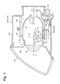
- Fig. 1 is a schematic sectional view showing an interior construction of a vehicle headlamp 210 according to an embodiment of the invention.
- the vehicle headlamp 210 shown in Fig. 1 is a variable light distribution headlamp which is disposed individually at each of the left- and right-hand sides of a front of a vehicle with respect to a vehicle's width direction.
- the interior construction is common between the left and right headlamps, and therefore, the construction of a vehicle headlamp 210R which is disposed at the right-hand side of the front of the vehicle will be described here and is representative of the constructions of the left and right headlamps,.
- the vehicle headlamp 210R has a lamp compartment 216 made up of a lamp body 212 having an opening portion in the direction of the front of the vehicle and a transparent cover 214, which covers the opening portion in the lamp body 212.
- a lamp unit 10 which shines light in the direction of the front of the vehicle is accommodated in the lamp compartment 216.
- a lamp bracket 218 having a pivot mechanism 218a which constitutes an oscillation center of the lamp unit 10 is formed at part of the lamp unit 10.
- the lamp bracket 218 is connected to a body bracket 220, which is provided on an inner wall surface of the lamp body 212 so as to be joined thereto by a fastening member such as a screw. Consequently, the lamp unit 10 is connected to a predetermined position within the lamp compartment 216 and is able to change its posture with respect to about the pivot mechanism 218a, for example, to a forward tilting posture or a rearward tilting posture.
- a rotating shaft 222a of a swivel actuator 222 is fixed to a lower surface of the lamp unit 10, and this swivel actuator 222 makes up an adaptive front-lighting system (AFS) to illuminate a road surface ahead in a traveling direction of a vehicle when the vehicle is driving on a curved road.
- the swivel actuator 222 swivels the lamp unit 10 about the pivot mechanism 218a in the traveling direction based on steering amount data, the shape of the road on which the vehicle is driving which is provided from a navigation system and a relative positional relationship between a preceding or oncoming vehicle and the subject vehicle.
- the swivel actuator 222 can include a stepping motor, for example.
- a solenoid can also be used.
- a unit bracket 224 is fixed to the swivel actuator 222.
- the leveling actuator 226 includes, for example, a motor which extends or contracts a rod 226a in a direction indicated by an arrow M or a direction indicated by an arrow N.
- the rod 226a is extended in the direction indicated by the arrow M
- the lamp unit 10 oscillates to take a rearward tilting posture about the pivot mechanism 218a.
- the rod 226a is contracted in the direction indicated by the arrow N
- the lamp unit 10 oscillates to take a forward tilting posture about the pivot mechanism 218a.
- a leveling control can be executed in which the optical axis is directed upwards.
- a leveling control can be executed in which the optical axis is directed downwards.
- the leveling control can also be executed in accordance with a posture of the vehicle while driving. For example, when the vehicle is accelerated while driving, the vehicle is tilted toward the rear, whereas when the vehicle is decelerated, the vehicle is tilted toward the front. Consequently, the light shining direction of the vehicle headlamp 210 also changes vertically as the vehicle is tilted in the way described above, whereby the forward light shining distance is extended or shortened. Then, the leveling control of the lamp unit 10 is executed on a real time basis based on the posture of the vehicle while driving, whereby the forward light shining distance can be controlled to be the optimum distance even when the vehicle is driving. This may be referred to as "automatic leveling.”
- a light shining control unit 228 for controlling the turning on and off of the lamp unit 10 and controlling the formation of a light distribution pattern is disposed on an inner wall surface of the lamp compartment 216 in a position lying below the lamp unit 10, for example.
- a light shining control unit 228R for controlling the vehicle headlamp 210R is disposed. This light shining control unit 228R also executes the control of the swivel actuator 222 and the leveling actuator 226.
- the lamp unit 10 can include an aiming control mechanism.
- an aiming pivot mechanism which constitutes a center of oscillation when an aiming control is executed is disposed at a connecting portion between the rod 226a of the leveling actuator 226 and the unit bracket 224.
- a pair of aiming control screws which move back and forth in a front-to-rear direction of the vehicle, is disposed at intervals in the vehicle's width direction at a connecting portion between the body bracket 220 and the lamp bracket 218. For example, when two aiming control screws are moved to the front, the lamp unit 10 is tilted about the aiming pivot mechanism toward the front, whereby the optical axis is controlled to be directed downwards.
- the lamp unit 10 is tilted toward the rear about the aiming pivot mechanism, whereby the optical axis is controlled to be directed upwards.
- the lamp unit 10 swivels about the aiming pivot mechanism toward the right, whereby the optical axis is controlled to be directed in a rightward direction.
- the lamp unit 10 swivels to the left about the aiming pivot mechanism, whereby the optical axis is controlled to be directed in a leftward direction.
- This aiming control is executed when a vehicle is shipped from an assembly plant or is subjected to a legal periodical inspection or when vehicle headlamps 210 are replaced. Then, the vehicle headlamp 210 is controlled so as to take a normal posture that is determined by the design of the headlamp, and the formation and control of a light distribution pattern according to the embodiment is executed based on that normal posture.
- the lamp unit 10 includes a shade mechanism 18 which includes the rotary shade 12, a bulb 14 as a light source, a lamp housing 17 which supports a reflector 16 on an inner wall thereof and a projection lens 20.
- an incandescent lamp, a halogen lamp, a discharge lamp and LEDs, for example, can be used as the bulb 14.
- the bulb 14 is described as employing a halogen lamp.
- the bulb 14 is mounted in a bulb mounting portion 15.
- the reflector 16 reflects light emitte4d from the bulb 14. Then, light emitted from the bulb 14 and light reflected from the reflector 16 are partially guided to the projection lens 20 by way of the rotary shade 12.
- the shade mechanism 18 includes the rotary shade 12, a shade support portion 13 which supports the rotary shade 12 and a motor (not shown) which rotates the rotary shade 12.
- the rotary shade 12 can form a plurality of light distribution patterns by use of light from the bulb 14.
- the rotary shade 12 is a member which can rotate about a rotating shaft 12a and includes a cylindrical member 12b, which extends in the direction of the rotating shaft 12a and a plurality of shade plates 12c which are disposed circumferentially at intervals on an outer circumferential surface of the cylindrical member 12b.
- the rotary shade 12 includes three shade plates 12 c1 to 12 c3 which have different shapes.
- the shade plate 12 c1 is a shade plate for forming a low-beam light distribution pattern
- the shade plate 12 c2 is a shade plate for forming a so-called left high-beam light distribution pattern
- the shade plate 12 c3 is a shade plate for forming a so-called right high-beam light distribution.
- the rotary shade 12 has a cutout portion 12d which results from cutting part of the rotary shade 12 in the direction of the rotating shaft 12a for forming a high-beam light distribution pattern.
- the three shade plates 12 c1 to 12 c3 and the cutout portion 12d function as a "light distribution pattern forming portion.”
- the rotary shade 12 is driven to rotate by the motor so as to move any one of the cutout portion 12d and the three shade plates 12 c1 to 12 c3 to the position of a rear focal plane FS, which includes a rear focal point of the projection lens 20. Then, a light distribution pattern which matches the shape of a ridge portion of the shade plate 12, which is situated on the rear focal plane, is formed. For example, a low-beam light distribution pattern is formed by moving the shade plate 12 c1 on to the rear focal plane so as to cut off part of light shone from the bulb 14. In addition, a high-beam light distribution pattern is formed by moving the cutout portion 12d on to the rear focal plane so as to allow light from the bulb 14 to pass by the rotary shade 12 and travel to the projection lens 20.
- the projection lens 20 is made up of a planoconvex aspherical lens which is convex on a front surface and is plane on a rear surface and projects a light source image formed on the rear focal plane FS on to an imaginary vertical screen ahead of the vehicle headlamp 210 as an inverted image.
- the projection lens 20 is disposed so that the bulb 14 is situated on an optical axis O thereof.
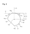
- Fig. 2 is a drawing depicting the rotary shade 12.
- portions 12e of the cylindrical member 12b which are located between the light distribution pattern forming portions are formed so that a vertical height of an area to which light is shone while light distribution patterns are being switched is not higher than a predetermined height.
- the predetermined height is set to a horizontal line, for example.
- the rotary shade 12 is configured so that a first distance D1 from the rotating shaft 12a to the portion between the light distribution pattern forming portions is not shorter than a second distance D2 from the rotating shaft 12a to the optical axis O of the projection lens 20.
- the portions 12e defined between the light distribution patterns include a portion 12 e1 defined between the shade plate 12 c1 and the shade plate 12 c2 , a portion 12 e2 defined between the shade plate 12 c2 and the cutout portion 12d, a portion 12 e3 defined between the cutout portion 12d and the shade plate 12 c3 , and a portion 12 e4 defined between the shade plate 12 c3 and the shade plate 12 c1 .
- Figs. 3A and 3B are drawings depicting a low-beam light distribution pattern.
- a low-beam light distribution pattern 300 shown in Fig. 3B is formed, the rotary shade 12 is rotated so that the shade plate 12 c1 is situated on the rear focal plane FS, as is shown in Fig. 3A .
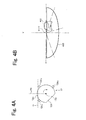
- Figs. 4A and 4B are drawings depicting a light distribution pattern which is produced when the light distribution patterns are switched.
- the rotary shade 12 is driven to rotate so that the shade plate situated on the rear focal plane FS is switched from the shade plate 12 c1 to the shade plate 12 c2 .
- the portion 12 e1 defined between the shade plate 12 c1 and the shade plate 12 c2 passes the rear focal plane FS while the shade plates are being switched.
- the first distance D1 from the rotating shaft 12a to the portion defined between the light distribution pattern forming portions is made to be not shorter than the second distance D2 from the rotating shaft 12a to the optical axis O of the projection lens 20. Therefore, light from the bulb 14 and the reflector 16 which attempts to pass below the optical axis O is cut off by the portion 12 e1 .
- Light that has passed the rotary shade 12 is projected inverted by the projection lens 20, and therefore, as is shown in Fig. 4B , a light distribution pattern 400 is formed in which the vertical height of the area to which light is shone is not higher than the predetermined height, thereby making it possible to suppress the generation of glare which blinds the driver of an oncoming vehicle 402.
- Fig. 4B shows that the light unit 10 is disposed so that a forward extension point of the optical axis O coincides with an H-V point on the imaginary vertical screen. Consequently, an upper end of the light distribution pattern 400 is situated not higher than the horizontal line H.
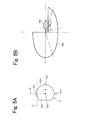
- Figs. 5A and 5B are drawings depicting a left high-beam light distribution pattern.
- a left-hand high-beam light distribution pattern 500 is formed as shown in Fig. 5B
- the rotary shade 12 is driven to rotate so that the shade plate 12c2 is situated on the rear focal plane FS as shown in Fig. 5A .
- the left high-beam light distribution pattern 500 is a light distribution which is suitable for a case in which there is an oncoming vehicle 502 or a pedestrian on a lane for oncoming vehicles.
- the light distribution pattern 500 is a light distribution pattern which takes into consideration the avoidance of a risk of blinding the driver of the oncoming vehicle 502 or the pedestrian with glare.
- the vehicle headlamp 210 according to the embodiment of the invention has been described heretofore.
- the first distance D from the rotating shaft 12a to the portions 12e defined between the light distribution pattern forming portions is made to be no shorter than the second distance D2 from the rotating shaft 12a to the optical axis O of the projection lens 20, thereby making it possible to suppress the generation of light which shines above the optical axis O, while the light distribution patterns are being switched. As a result of this, it becomes difficult to blind the driver of a preceding or oncoming vehicle with glare.
- the portions 12e of the rotary shade 12 defined between the light distribution pattern forming portions are made to be lower than the heights of the light distribution pattern forming portions.
Landscapes
- Engineering & Computer Science (AREA)
- General Engineering & Computer Science (AREA)
- Non-Portable Lighting Devices Or Systems Thereof (AREA)
Abstract
Description
- The present invention relates to a vehicle headlamp and more particularly to a vehicle headlamp which can change light distribution patterns.
- Vehicle headlamps which employ a rotating-type shade have been known (herein after, referred to as a rotary shade (see
JP-A-2010-86863 - However, in the vehicle headlamp which employs the related art rotary shade, a flash of light occurs due to light from the light source being cut off appropriately when the light distribution patterns are switched or when the shade plates are switched, leading to fears that drivers of vehicles running ahead of the subject vehicle, including oncoming vehicles and preceding vehicles, are temporarily blinded by glare.
- Embodiments of the present invention have been made in view of these situations, and an object thereof is to provide a vehicle headlamp which can make it difficult for drivers of vehicles running ahead of the subject vehicles to be blinded with glare produced when the light distribution patterns are switched.
- With a view to solving the problem, according to an aspect of the invention, there is provided a vehicle headlamp comprising a mounting portion with a light source mounted to the mounting portion, a rotary shade for forming a plurality of light distribution patterns using light from the light source, wherein the rotary shade is driven to rotate so as to select and form any one of the plurality of light distribution patterns, and wherein the rotary shade comprises a cylindrical member, which extends in the direction of a rotating shaft and a plurality of light distribution pattern forming portions, which are disposed circumferentially at intervals on an outer circumferential surface of the cylindrical member, and a projection lens for projecting light which passes through the rotary shade toward the front of a vehicle. Portions of the cylindrical member which are located between the light distribution pattern forming portions are formed so that a vertical height of an area to which light is shone while the light distribution patterns are switched is not higher than a predetermined height.
- According to this aspect, the vertical height of the area to which light is shone while the light distribution patterns are switch is not higher than the predetermined height. For example, when the predetermined height is set at a horizontal line, the shining of light above the horizontal line when the light distribution patterns are switch can be suppressed, whereby it may become difficult to blind drivers of preceding and/or oncoming vehicles with glare.
- A first distance from the rotating shaft to the portion located between the light distribution pattern forming portions may be equal to or longer than a second distance from the rotating shaft to an optical axis of the projection lens. As this occurs, the shining of light above the optical axis when the light distribution patterns are switch can be suppressed, whereby it may become difficult to blind drivers of preceding and/or oncoming vehicles with glare.
- According to the invention, the vehicle headlamp can be provided which can make it difficult for drivers of preceding and/or oncoming vehicles to be blinded by glare produced when the light distribution patterns are switched.
- A general configuration that implements the various features of an embodiment of the invention will be described with reference to the drawings. The drawings and the associated descriptions are provided to illustrate embodiments of the invention and should not limit the scope of the invention.
-
Fig. 1 is a schematic sectional view showing an interior construction of a vehicle headlamp according to an embodiment of the invention. -
Fig. 2 is a drawing depicting a rotary shade. -
Figs. 3A and 3B show drawings depicting a low-beam light distribution pattern. -
Figs. 4A and 4B show drawings depicting a light distribution pattern produced when light distribution patterns are switched. -
Figs. 5A and 5B show drawings depicting a left high-beam light distribution pattern. - Hereinafter, an embodiment of the invention will be described in detail by reference to the drawings.
-
Fig. 1 is a schematic sectional view showing an interior construction of avehicle headlamp 210 according to an embodiment of the invention. Thevehicle headlamp 210 shown inFig. 1 is a variable light distribution headlamp which is disposed individually at each of the left- and right-hand sides of a front of a vehicle with respect to a vehicle's width direction. The interior construction is common between the left and right headlamps, and therefore, the construction of avehicle headlamp 210R which is disposed at the right-hand side of the front of the vehicle will be described here and is representative of the constructions of the left and right headlamps,. - The
vehicle headlamp 210R has alamp compartment 216 made up of alamp body 212 having an opening portion in the direction of the front of the vehicle and atransparent cover 214, which covers the opening portion in thelamp body 212. Alamp unit 10 which shines light in the direction of the front of the vehicle is accommodated in thelamp compartment 216. Alamp bracket 218 having apivot mechanism 218a which constitutes an oscillation center of thelamp unit 10 is formed at part of thelamp unit 10. Thelamp bracket 218 is connected to abody bracket 220, which is provided on an inner wall surface of thelamp body 212 so as to be joined thereto by a fastening member such as a screw. Consequently, thelamp unit 10 is connected to a predetermined position within thelamp compartment 216 and is able to change its posture with respect to about thepivot mechanism 218a, for example, to a forward tilting posture or a rearward tilting posture. - In addition, a rotating
shaft 222a of aswivel actuator 222 is fixed to a lower surface of thelamp unit 10, and thisswivel actuator 222 makes up an adaptive front-lighting system (AFS) to illuminate a road surface ahead in a traveling direction of a vehicle when the vehicle is driving on a curved road. Theswivel actuator 222 swivels thelamp unit 10 about thepivot mechanism 218a in the traveling direction based on steering amount data, the shape of the road on which the vehicle is driving which is provided from a navigation system and a relative positional relationship between a preceding or oncoming vehicle and the subject vehicle. As a result of this, the illumination area of thelamp unit 10 is not directed to the front of the vehicle but is directed to a position farther along the curved road so as to improve the forward visibility of the driver. Theswivel actuator 222 can include a stepping motor, for example. When the swivel angle is fixed to a predetermined value, a solenoid can also be used. - A
unit bracket 224 is fixed to theswivel actuator 222. A levelingactuator 226, which is disposed outside thelamp body 212, is connected to theunit bracket 224. The levelingactuator 226 includes, for example, a motor which extends or contracts arod 226a in a direction indicated by an arrow M or a direction indicated by an arrow N. When therod 226a is extended in the direction indicated by the arrow M, thelamp unit 10 oscillates to take a rearward tilting posture about thepivot mechanism 218a. Conversely, when therod 226a is contracted in the direction indicated by the arrow N, thelamp unit 10 oscillates to take a forward tilting posture about thepivot mechanism 218a. When thelamp unit 10 is tilted to the rear, a leveling control can be executed in which the optical axis is directed upwards. In contrast, when thelamp unit 10 is tilted to the front, a leveling control can be executed in which the optical axis is directed downwards. By executing the leveling control in the way described above, the optical axis can be controlled so as to match the posture of the vehicle. As a result of this, a forward reaching distance of light emitted from thevehicle headlamp 210 can be controlled to an optimum distance. - The leveling control can also be executed in accordance with a posture of the vehicle while driving. For example, when the vehicle is accelerated while driving, the vehicle is tilted toward the rear, whereas when the vehicle is decelerated, the vehicle is tilted toward the front. Consequently, the light shining direction of the
vehicle headlamp 210 also changes vertically as the vehicle is tilted in the way described above, whereby the forward light shining distance is extended or shortened. Then, the leveling control of thelamp unit 10 is executed on a real time basis based on the posture of the vehicle while driving, whereby the forward light shining distance can be controlled to be the optimum distance even when the vehicle is driving. This may be referred to as "automatic leveling." - A light
shining control unit 228 for controlling the turning on and off of thelamp unit 10 and controlling the formation of a light distribution pattern is disposed on an inner wall surface of thelamp compartment 216 in a position lying below thelamp unit 10, for example. In the case ofFig. 1 , a lightshining control unit 228R for controlling thevehicle headlamp 210R is disposed. This lightshining control unit 228R also executes the control of theswivel actuator 222 and the levelingactuator 226. - The
lamp unit 10 can include an aiming control mechanism. For example, an aiming pivot mechanism which constitutes a center of oscillation when an aiming control is executed is disposed at a connecting portion between therod 226a of the levelingactuator 226 and theunit bracket 224. In addition, a pair of aiming control screws, which move back and forth in a front-to-rear direction of the vehicle, is disposed at intervals in the vehicle's width direction at a connecting portion between thebody bracket 220 and thelamp bracket 218. For example, when two aiming control screws are moved to the front, thelamp unit 10 is tilted about the aiming pivot mechanism toward the front, whereby the optical axis is controlled to be directed downwards. Similarly, when the two aiming control screws are retracted to the rear, thelamp unit 10 is tilted toward the rear about the aiming pivot mechanism, whereby the optical axis is controlled to be directed upwards. When the left-hand side aiming control screw in the vehicle' s width direction is moved to the front, thelamp unit 10 swivels about the aiming pivot mechanism toward the right, whereby the optical axis is controlled to be directed in a rightward direction. When the right-hand side aiming control screw in the vehicle's width direction is moved to the front, thelamp unit 10 swivels to the left about the aiming pivot mechanism, whereby the optical axis is controlled to be directed in a leftward direction. This aiming control is executed when a vehicle is shipped from an assembly plant or is subjected to a legal periodical inspection or when vehicle headlamps 210 are replaced. Then, thevehicle headlamp 210 is controlled so as to take a normal posture that is determined by the design of the headlamp, and the formation and control of a light distribution pattern according to the embodiment is executed based on that normal posture. - The
lamp unit 10 includes ashade mechanism 18 which includes therotary shade 12, abulb 14 as a light source, alamp housing 17 which supports areflector 16 on an inner wall thereof and aprojection lens 20. - An incandescent lamp, a halogen lamp, a discharge lamp and LEDs, for example, can be used as the
bulb 14. In this embodiment, thebulb 14 is described as employing a halogen lamp. Thebulb 14 is mounted in abulb mounting portion 15. Thereflector 16 reflects light emitte4d from thebulb 14. Then, light emitted from thebulb 14 and light reflected from thereflector 16 are partially guided to theprojection lens 20 by way of therotary shade 12. - The
shade mechanism 18 includes therotary shade 12, a shade support portion 13 which supports therotary shade 12 and a motor (not shown) which rotates therotary shade 12. Therotary shade 12 can form a plurality of light distribution patterns by use of light from thebulb 14. - The
rotary shade 12 is a member which can rotate about arotating shaft 12a and includes acylindrical member 12b, which extends in the direction of therotating shaft 12a and a plurality of shade plates 12c which are disposed circumferentially at intervals on an outer circumferential surface of thecylindrical member 12b. - In this embodiment, the
rotary shade 12 includes threeshade plates 12c1 to 12c3 which have different shapes. Theshade plate 12c1 is a shade plate for forming a low-beam light distribution pattern, theshade plate 12c2 is a shade plate for forming a so-called left high-beam light distribution pattern, and theshade plate 12c3 is a shade plate for forming a so-called right high-beam light distribution. Therotary shade 12 has acutout portion 12d which results from cutting part of therotary shade 12 in the direction of therotating shaft 12a for forming a high-beam light distribution pattern. The threeshade plates 12c1 to 12c3 and thecutout portion 12d function as a "light distribution pattern forming portion." - The
rotary shade 12 is driven to rotate by the motor so as to move any one of thecutout portion 12d and the threeshade plates 12c1 to 12c3 to the position of a rear focal plane FS, which includes a rear focal point of theprojection lens 20. Then, a light distribution pattern which matches the shape of a ridge portion of theshade plate 12, which is situated on the rear focal plane, is formed. For example, a low-beam light distribution pattern is formed by moving theshade plate 12c1 on to the rear focal plane so as to cut off part of light shone from thebulb 14. In addition, a high-beam light distribution pattern is formed by moving thecutout portion 12d on to the rear focal plane so as to allow light from thebulb 14 to pass by therotary shade 12 and travel to theprojection lens 20. - The
projection lens 20 is made up of a planoconvex aspherical lens which is convex on a front surface and is plane on a rear surface and projects a light source image formed on the rear focal plane FS on to an imaginary vertical screen ahead of thevehicle headlamp 210 as an inverted image. Theprojection lens 20 is disposed so that thebulb 14 is situated on an optical axis O thereof. -
Fig. 2 is a drawing depicting therotary shade 12. In therotary shade 12 according to this embodiment, portions 12e of thecylindrical member 12b which are located between the light distribution pattern forming portions are formed so that a vertical height of an area to which light is shone while light distribution patterns are being switched is not higher than a predetermined height. The predetermined height is set to a horizontal line, for example. In order to realize a configuration like this, therotary shade 12 is configured so that a first distance D1 from therotating shaft 12a to the portion between the light distribution pattern forming portions is not shorter than a second distance D2 from therotating shaft 12a to the optical axis O of theprojection lens 20. The portions 12e defined between the light distribution patterns include aportion 12e1 defined between theshade plate 12c1 and theshade plate 12c2, aportion 12e2 defined between theshade plate 12c2 and thecutout portion 12d, aportion 12e3 defined between thecutout portion 12d and theshade plate 12c3, and aportion 12e4 defined between theshade plate 12c3 and theshade plate 12c1. - Next, the operation of the
vehicle headlamp 210 will be described by use ofFigs. 3A to 5B .Figs. 3A and 3B are drawings depicting a low-beam light distribution pattern. When a low-beamlight distribution pattern 300 shown inFig. 3B is formed, therotary shade 12 is rotated so that theshade plate 12c1 is situated on the rear focal plane FS, as is shown inFig. 3A . -
Figs. 4A and 4B are drawings depicting a light distribution pattern which is produced when the light distribution patterns are switched. When the light distribution pattern is switched from the low-beam light distribution pattern to the left high-beam light distribution pattern, therotary shade 12 is driven to rotate so that the shade plate situated on the rear focal plane FS is switched from theshade plate 12c1 to theshade plate 12c2. As is shown inFig. 4A , theportion 12e1 defined between theshade plate 12c1 and theshade plate 12c2 passes the rear focal plane FS while the shade plates are being switched. As has been described above, in this embodiment, the first distance D1 from therotating shaft 12a to the portion defined between the light distribution pattern forming portions is made to be not shorter than the second distance D2 from therotating shaft 12a to the optical axis O of theprojection lens 20. Therefore, light from thebulb 14 and thereflector 16 which attempts to pass below the optical axis O is cut off by theportion 12e1. Light that has passed therotary shade 12 is projected inverted by theprojection lens 20, and therefore, as is shown inFig. 4B , alight distribution pattern 400 is formed in which the vertical height of the area to which light is shone is not higher than the predetermined height, thereby making it possible to suppress the generation of glare which blinds the driver of anoncoming vehicle 402.Fig. 4B shows that thelight unit 10 is disposed so that a forward extension point of the optical axis O coincides with an H-V point on the imaginary vertical screen. Consequently, an upper end of thelight distribution pattern 400 is situated not higher than the horizontal line H. -
Figs. 5A and 5B are drawings depicting a left high-beam light distribution pattern. When a left-hand high-beamlight distribution pattern 500 is formed as shown inFig. 5B , therotary shade 12 is driven to rotate so that the shade plate 12c2 is situated on the rear focal plane FS as shown inFig. 5A . - The left high-beam
light distribution pattern 500 is a light distribution which is suitable for a case in which there is anoncoming vehicle 502 or a pedestrian on a lane for oncoming vehicles. In other words, thelight distribution pattern 500 is a light distribution pattern which takes into consideration the avoidance of a risk of blinding the driver of theoncoming vehicle 502 or the pedestrian with glare. - Thus, the
vehicle headlamp 210 according to the embodiment of the invention has been described heretofore. According to thevehicle headlamp 210, the first distance D from therotating shaft 12a to the portions 12e defined between the light distribution pattern forming portions is made to be no shorter than the second distance D2 from therotating shaft 12a to the optical axis O of theprojection lens 20, thereby making it possible to suppress the generation of light which shines above the optical axis O, while the light distribution patterns are being switched. As a result of this, it becomes difficult to blind the driver of a preceding or oncoming vehicle with glare. - In addition, in the
vehicle headlamp 210 according to the embodiment, the portions 12e of therotary shade 12 defined between the light distribution pattern forming portions are made to be lower than the heights of the light distribution pattern forming portions. By adopting this configuration, light cut off by the portions 12e defined between the light distribution pattern forming portions can be reduced, thereby making it possible to increase the luminous intensity of the formed light distribution patterns. - Thus, the invention has been described based on the embodiment. The embodiment is merely an example, and hence, it is obvious to those skilled in the art to which the invention pertains that various modifications can be made to the embodiment with respect to combinations of the constituent elements and operation processes thereof and that these modified examples also fall within the scope of the invention.
Claims (2)
- A vehicle headlamp comprising:a mounting portion with a light source mounted to the mounting portion;a rotary shade for forming a plurality of light distribution patterns using light from the light source,wherein the rotary shade is driven to rotate so as to select and form any one of the plurality of light distribution patterns, andwherein the rotary shade comprises a cylindrical member, which extends in the direction of a rotating shaft and a plurality of light distribution pattern forming portions, which are disposed circumferentially at intervals on an outer circumferential surface of the cylindrical member; anda projection lens for projecting light which passes through the rotary shade toward the front of a vehicle,wherein portions of the cylindrical member which are located between the light distribution pattern forming portions are formed so that a vertical height of an area to which light is shone while the light distribution patterns are being switched is not higher than a predetermined height.
- A vehicle headlamp according to Claim 1, whereina first distance from the rotating shaft to the portions of the cylindrical member located between the light distribution pattern forming portions is not shorter than a second distance from the rotating shaft to an optical axis of the projection lens.
Applications Claiming Priority (1)
| Application Number | Priority Date | Filing Date | Title |
|---|---|---|---|
| JP2010211672A JP5610949B2 (en) | 2010-09-22 | 2010-09-22 | Vehicle headlamp |
Publications (1)
| Publication Number | Publication Date |
|---|---|
| EP2434210A1 true EP2434210A1 (en) | 2012-03-28 |
Family
ID=44677650
Family Applications (1)
| Application Number | Title | Priority Date | Filing Date |
|---|---|---|---|
| EP11180490A Withdrawn EP2434210A1 (en) | 2010-09-22 | 2011-09-08 | Vehicle headlamp |
Country Status (2)
| Country | Link |
|---|---|
| EP (1) | EP2434210A1 (en) |
| JP (1) | JP5610949B2 (en) |
Cited By (2)
| Publication number | Priority date | Publication date | Assignee | Title |
|---|---|---|---|---|
| DE102012112598A1 (en) * | 2012-12-19 | 2014-06-26 | Dr. Ing. H.C. F. Porsche Aktiengesellschaft | Lighting device for motor vehicle, has projection module that is provided with projection element and thread-like extending bevel portion for representation of dynamic curve light |
| EP2853804A1 (en) * | 2013-09-30 | 2015-04-01 | Valeo Vision | Lighting and/or signalling module with a plurality of rotary optical systems |
Citations (7)
| Publication number | Priority date | Publication date | Assignee | Title |
|---|---|---|---|---|
| JPH0729401A (en) * | 1993-07-15 | 1995-01-31 | Koito Mfg Co Ltd | Projection type automobile headlamp |
| US20050024889A1 (en) * | 2003-05-22 | 2005-02-03 | Atsushi Sugimoto | Vehicle headlamp |
| US20070195543A1 (en) * | 2006-02-17 | 2007-08-23 | Atsushi Sugimoto | Vehicle headlamp |
| US20090310378A1 (en) * | 2008-06-11 | 2009-12-17 | Koito Manufacturing Co., Ltd. | Headlamp for vehicle |
| JP2010086863A (en) | 2008-10-01 | 2010-04-15 | Koito Mfg Co Ltd | Vehicular headlight device |
| EP2244007A1 (en) * | 2009-04-24 | 2010-10-27 | Valeo Vision | Optical device for an automobile |
| EP2339777A2 (en) * | 2002-01-30 | 2011-06-29 | Tecsec, Incorporated | Method of authenticating a user to use a system |
Family Cites Families (3)
| Publication number | Priority date | Publication date | Assignee | Title |
|---|---|---|---|---|
| JP2548801Y2 (en) * | 1991-10-08 | 1997-09-24 | 株式会社小糸製作所 | Projection type automotive headlamp |
| JPH0741809U (en) * | 1993-12-27 | 1995-07-21 | 株式会社小糸製作所 | Car headlamp |
| JP2005259549A (en) * | 2004-03-12 | 2005-09-22 | Koito Mfg Co Ltd | Projection type automotive headlamp |
-
2010
- 2010-09-22 JP JP2010211672A patent/JP5610949B2/en not_active Expired - Fee Related
-
2011
- 2011-09-08 EP EP11180490A patent/EP2434210A1/en not_active Withdrawn
Patent Citations (7)
| Publication number | Priority date | Publication date | Assignee | Title |
|---|---|---|---|---|
| JPH0729401A (en) * | 1993-07-15 | 1995-01-31 | Koito Mfg Co Ltd | Projection type automobile headlamp |
| EP2339777A2 (en) * | 2002-01-30 | 2011-06-29 | Tecsec, Incorporated | Method of authenticating a user to use a system |
| US20050024889A1 (en) * | 2003-05-22 | 2005-02-03 | Atsushi Sugimoto | Vehicle headlamp |
| US20070195543A1 (en) * | 2006-02-17 | 2007-08-23 | Atsushi Sugimoto | Vehicle headlamp |
| US20090310378A1 (en) * | 2008-06-11 | 2009-12-17 | Koito Manufacturing Co., Ltd. | Headlamp for vehicle |
| JP2010086863A (en) | 2008-10-01 | 2010-04-15 | Koito Mfg Co Ltd | Vehicular headlight device |
| EP2244007A1 (en) * | 2009-04-24 | 2010-10-27 | Valeo Vision | Optical device for an automobile |
Cited By (3)
| Publication number | Priority date | Publication date | Assignee | Title |
|---|---|---|---|---|
| DE102012112598A1 (en) * | 2012-12-19 | 2014-06-26 | Dr. Ing. H.C. F. Porsche Aktiengesellschaft | Lighting device for motor vehicle, has projection module that is provided with projection element and thread-like extending bevel portion for representation of dynamic curve light |
| EP2853804A1 (en) * | 2013-09-30 | 2015-04-01 | Valeo Vision | Lighting and/or signalling module with a plurality of rotary optical systems |
| FR3011310A1 (en) * | 2013-09-30 | 2015-04-03 | Valeo Vision | LIGHTING AND / OR SIGNALING MODULE WITH MULTIPLE ROTARY OPTICAL SYSTEMS |
Also Published As
| Publication number | Publication date |
|---|---|
| JP2012069312A (en) | 2012-04-05 |
| JP5610949B2 (en) | 2014-10-22 |
Similar Documents
| Publication | Publication Date | Title |
|---|---|---|
| JP5833861B2 (en) | Vehicle headlamp device and light distribution control method | |
| JP5398443B2 (en) | Vehicle headlamp device | |
| KR101239454B1 (en) | Vehicular headlamp apparatus | |
| EP2154426B1 (en) | Vehicle headlamp apparatus | |
| JP5546326B2 (en) | Control device, vehicle lamp system, vehicle lamp | |
| US20050201117A1 (en) | Projector type vehicle headlamp | |
| JP5074888B2 (en) | Vehicle lamp system | |
| JP2010000957A (en) | Headlight device for vehicle | |
| JP2018073485A (en) | Optical unit | |
| JP7155124B2 (en) | Lighting units and vehicle headlights | |
| JP5430282B2 (en) | Light distribution control system for vehicle headlamps | |
| EP2388164B1 (en) | Vehicle Headlamp system, control device, vehicle headlamp, and control method of vehicle headlamp | |
| EP2230128B1 (en) | Automotive headlamp apparatus for controlling light distribution pattern | |
| EP2100771B1 (en) | Vehicle headlight apparatus and method for controlling same | |
| JP5539796B2 (en) | Vehicle headlight system | |
| US7118258B2 (en) | Vehicular headlamp | |
| JP4547571B2 (en) | Vehicle headlamp and light-shielding shutter driving device | |
| JP5634406B2 (en) | Vehicle headlamp device | |
| US7470050B2 (en) | Vehicle light | |
| EP2384933B1 (en) | Vehicle headlamp system, control device and vehicle headlamp | |
| JP5610949B2 (en) | Vehicle headlamp | |
| JP2011148372A (en) | Headlight control system | |
| JP2009211964A (en) | Vehicular lamp system | |
| JP5117938B2 (en) | Vehicle headlamp device | |
| JP2011238378A (en) | Lamp fixture system for vehicle, control device, and lamp fixture for vehicle |
Legal Events
| Date | Code | Title | Description |
|---|---|---|---|
| PUAI | Public reference made under article 153(3) epc to a published international application that has entered the european phase |
Free format text: ORIGINAL CODE: 0009012 |
|
| 17P | Request for examination filed |
Effective date: 20110908 |
|
| AK | Designated contracting states |
Kind code of ref document: A1 Designated state(s): AL AT BE BG CH CY CZ DE DK EE ES FI FR GB GR HR HU IE IS IT LI LT LU LV MC MK MT NL NO PL PT RO RS SE SI SK SM TR |
|
| AX | Request for extension of the european patent |
Extension state: BA ME |
|
| STAA | Information on the status of an ep patent application or granted ep patent |
Free format text: STATUS: EXAMINATION IS IN PROGRESS |
|
| STAA | Information on the status of an ep patent application or granted ep patent |
Free format text: STATUS: THE APPLICATION HAS BEEN WITHDRAWN |
|
| 17Q | First examination report despatched |
Effective date: 20180711 |
|
| 18W | Application withdrawn |
Effective date: 20180726 |