EP2434193A2 - Circumferential clamp and latching assembly - Google Patents
Circumferential clamp and latching assembly Download PDFInfo
- Publication number
- EP2434193A2 EP2434193A2 EP11178579A EP11178579A EP2434193A2 EP 2434193 A2 EP2434193 A2 EP 2434193A2 EP 11178579 A EP11178579 A EP 11178579A EP 11178579 A EP11178579 A EP 11178579A EP 2434193 A2 EP2434193 A2 EP 2434193A2
- Authority
- EP
- European Patent Office
- Prior art keywords
- latching
- clamping band
- latching device
- circumferential
- devices
- Prior art date
- Legal status (The legal status is an assumption and is not a legal conclusion. Google has not performed a legal analysis and makes no representation as to the accuracy of the status listed.)
- Withdrawn
Links
- 238000010168 coupling process Methods 0.000 description 3
- 238000005859 coupling reaction Methods 0.000 description 3
- 230000008878 coupling Effects 0.000 description 2
- 238000005452 bending Methods 0.000 description 1
- 230000000694 effects Effects 0.000 description 1
- 125000006850 spacer group Chemical group 0.000 description 1
Images


Classifications
-
- F—MECHANICAL ENGINEERING; LIGHTING; HEATING; WEAPONS; BLASTING
- F16—ENGINEERING ELEMENTS AND UNITS; GENERAL MEASURES FOR PRODUCING AND MAINTAINING EFFECTIVE FUNCTIONING OF MACHINES OR INSTALLATIONS; THERMAL INSULATION IN GENERAL
- F16L—PIPES; JOINTS OR FITTINGS FOR PIPES; SUPPORTS FOR PIPES, CABLES OR PROTECTIVE TUBING; MEANS FOR THERMAL INSULATION IN GENERAL
- F16L23/00—Flanged joints
- F16L23/04—Flanged joints the flanges being connected by members tensioned in the radial plane
- F16L23/08—Flanged joints the flanges being connected by members tensioned in the radial plane connection by tangentially arranged pin and nut
- F16L23/10—Flanged joints the flanges being connected by members tensioned in the radial plane connection by tangentially arranged pin and nut with a pivoting or swinging pin
-
- B—PERFORMING OPERATIONS; TRANSPORTING
- B62—LAND VEHICLES FOR TRAVELLING OTHERWISE THAN ON RAILS
- B62B—HAND-PROPELLED VEHICLES, e.g. HAND CARTS OR PERAMBULATORS; SLEDGES
- B62B2203/00—Grasping, holding, supporting the objects
- B62B2203/44—Clamping or supporting circumferentially
-
- F—MECHANICAL ENGINEERING; LIGHTING; HEATING; WEAPONS; BLASTING
- F16—ENGINEERING ELEMENTS AND UNITS; GENERAL MEASURES FOR PRODUCING AND MAINTAINING EFFECTIVE FUNCTIONING OF MACHINES OR INSTALLATIONS; THERMAL INSULATION IN GENERAL
- F16B—DEVICES FOR FASTENING OR SECURING CONSTRUCTIONAL ELEMENTS OR MACHINE PARTS TOGETHER, e.g. NAILS, BOLTS, CIRCLIPS, CLAMPS, CLIPS OR WEDGES; JOINTS OR JOINTING
- F16B2200/00—Constructional details of connections not covered for in other groups of this subclass
- F16B2200/69—Redundant disconnection blocking means
-
- Y—GENERAL TAGGING OF NEW TECHNOLOGICAL DEVELOPMENTS; GENERAL TAGGING OF CROSS-SECTIONAL TECHNOLOGIES SPANNING OVER SEVERAL SECTIONS OF THE IPC; TECHNICAL SUBJECTS COVERED BY FORMER USPC CROSS-REFERENCE ART COLLECTIONS [XRACs] AND DIGESTS
- Y10—TECHNICAL SUBJECTS COVERED BY FORMER USPC
- Y10T—TECHNICAL SUBJECTS COVERED BY FORMER US CLASSIFICATION
- Y10T24/00—Buckles, buttons, clasps, etc.
- Y10T24/14—Bale and package ties, hose clamps
- Y10T24/1412—Bale and package ties, hose clamps with tighteners
- Y10T24/1416—Winder
-
- Y—GENERAL TAGGING OF NEW TECHNOLOGICAL DEVELOPMENTS; GENERAL TAGGING OF CROSS-SECTIONAL TECHNOLOGIES SPANNING OVER SEVERAL SECTIONS OF THE IPC; TECHNICAL SUBJECTS COVERED BY FORMER USPC CROSS-REFERENCE ART COLLECTIONS [XRACs] AND DIGESTS
- Y10—TECHNICAL SUBJECTS COVERED BY FORMER USPC
- Y10T—TECHNICAL SUBJECTS COVERED BY FORMER US CLASSIFICATION
- Y10T24/00—Buckles, buttons, clasps, etc.
- Y10T24/14—Bale and package ties, hose clamps
- Y10T24/1412—Bale and package ties, hose clamps with tighteners
- Y10T24/1441—Tangential screw
- Y10T24/1443—Adjustable girth
-
- Y—GENERAL TAGGING OF NEW TECHNOLOGICAL DEVELOPMENTS; GENERAL TAGGING OF CROSS-SECTIONAL TECHNOLOGIES SPANNING OVER SEVERAL SECTIONS OF THE IPC; TECHNICAL SUBJECTS COVERED BY FORMER USPC CROSS-REFERENCE ART COLLECTIONS [XRACs] AND DIGESTS
- Y10—TECHNICAL SUBJECTS COVERED BY FORMER USPC
- Y10T—TECHNICAL SUBJECTS COVERED BY FORMER US CLASSIFICATION
- Y10T24/00—Buckles, buttons, clasps, etc.
- Y10T24/14—Bale and package ties, hose clamps
- Y10T24/1412—Bale and package ties, hose clamps with tighteners
- Y10T24/1441—Tangential screw
- Y10T24/1453—Pivotal strap parts
-
- Y—GENERAL TAGGING OF NEW TECHNOLOGICAL DEVELOPMENTS; GENERAL TAGGING OF CROSS-SECTIONAL TECHNOLOGIES SPANNING OVER SEVERAL SECTIONS OF THE IPC; TECHNICAL SUBJECTS COVERED BY FORMER USPC CROSS-REFERENCE ART COLLECTIONS [XRACs] AND DIGESTS
- Y10—TECHNICAL SUBJECTS COVERED BY FORMER USPC
- Y10T—TECHNICAL SUBJECTS COVERED BY FORMER US CLASSIFICATION
- Y10T24/00—Buckles, buttons, clasps, etc.
- Y10T24/44—Clasp, clip, support-clamp, or required component thereof
- Y10T24/44291—Clasp, clip, support-clamp, or required component thereof including pivoted gripping member
- Y10T24/44547—Clasp, clip, support-clamp, or required component thereof including pivoted gripping member having inserted and receiving interlocking engaging faces
Definitions
- This invention relates to a circumferential clamp and a latching assembly.
- Circumferential clamp couplings typically comprise a pair of hinged jaws which clamp about respective flanges at the ends of the parts to be clamped together.
- the jaws are secured together at their free ends by a latch, for example fastener such as a bolt pivotally mounted to one of the jaws which latches over the end of the opposite jaw. Once latched, the jaws are clamped together by tightening the latch.
- a latch for example fastener such as a bolt pivotally mounted to one of the jaws which latches over the end of the opposite jaw.
- the redundant latch is disposed adjacent to and radially outward (with respect to the center of the clamp) of the primary fastener.
- This arrangement is bulky and occupies a large amount of radial space outwardly of the clamp. Furthermore, the moment generated by the radially outer redundant latch about the center of the clamp is greater than that of the primary latch, and so produces high stresses in the clamp.
- a further disadvantage associated with this arrangement is that it is possible to access, and so further tighten, the redundant fastener once the primary fastener has been tightened with the consequence that the fasteners can be alternately tightened putting progressively more stress into the coupling.
- a circumferential clamp comprising a clamping band having oppositely disposed circumferential ends and a latching assembly for securing the ends together, the latching assembly comprising first and second latching devices, each of which comprises an elongate element which is pivotably mounted on the clamping band adjacent one of the ends and is engageable with the clamping band adjacent the other end to latch the ends together, the lengthwise axes of the elongate elements lying in, or intersecting, a common plane tangential to the clamping band.
- the lengthwise axes of the elongate elements may be coincident with, or intersect, each other.
- the elongate elements of the first and second latching devices may be mounted on the clamping band to pivot about a common axis.
- the second latching device may obstruct access to the first latching device when the ends of the clamping band are latched together by the first and second latching devices.
- the second latching device may comprise at least one linkage which is offset from the lengthwise axis of the second latching device so as to accommodate the first latching device.
- the or each linkage may comprise a plurality of stacked plate links, each plate link extending parallel to the lengthwise axis of the second latching device.
- the first latching device may be disposed between plate links of the linkage when the ends of the clamping band are latched together by the first and second latching devices.
- a latching assembly for securing two components together, the latching assembly comprising first and second latching devices, each of which comprises an elongate element which is pivotably mounted to one of the components and is engagable with the other component to latch the components together, the lengthwise axes of the elongate elements being coincident with, or intersecting, each other.
- Figure 1 shows part of a circumferential clamp 2 comprising a clamping band 4 and a latching assembly 6.
- the latching assembly 6 is shown fully latched.
- the clamping band 4 is shown only in part. It will be appreciated that the clamping band 4 extends in a complete loop, thereby defining a longitudinal axis about which the clamping band 4 clamps.
- the clamping band 4 has two oppositely disposed first and second circumferential ends 8, 10 which are secured together by the latching assembly 6.
- the latching assembly 6 comprises a first latching device 12 and a second latching device 14.
- the first latching device 12 comprises a first eyebolt 16 having an eye 18 (not visible) at one end, a threaded section 20 towards the other end and a threaded fastener 22 having a non-circular profile, for example a nut, engaged with the threaded section 20.
- the lengthwise axis of the first eyebolt 16 defines the lengthwise axis of the first latching device 12.
- the first latching device 12 further comprises a semi-cylindrical washer 24 having a convex surface and a flat surface (for example a barrel-type washer such as a saddle washer) arranged about the shank of the eyebolt 18 between the threaded fastener 22 and the eye 18.
- the first latching device 12 is secured to the first circumferential end 8 by a clevis arrangement comprising a pin 21 which extends across a recess 23 in the first circumferential end 8 of the clamping band 4 and through the eye 18 of the first eyebolt 16.
- the pin 21 extends through the walls of the recess 23 and in a direction which is parallel to the longitudinal axis of the clamping band 4.
- the pin 21 can rotate with respect to the walls of the recess 23 and the eyebolt 16.
- the pin 21 is held in place by circlips, crimped washers, swaged ends, steps or other suitable means.
- the clevis arrangement permits the first latching device 12 to pivot in a plane which is perpendicular to the longitudinal axis of the clamping band 4.
- the second latching device 14 comprises two parallel elongate links 26 connecting a second eyebolt 28 to the first circumferential end 8, a second threaded fastener and a second semi-cylindrical washer 36.
- Each link 26 is secured to the respective ends of the pin 21 which extend through, and protrude from, the walls of the recess 23.
- the links 26 are therefore pivotally connected to the first circumferential end 8 on opposite sides of the clamping band 4.
- the links 26 are arranged to pivot independently of the first latching device 12 in respective planes that are parallel to the plane in which the first latching device 12 pivots.
- the second eyebolt 28 is secured to the free ends of the links 26 by a further clevis arrangement comprising a second pin 31 passing through the free ends of the links 26 and an eye 30 (not visible) of the second eyebolt 28.
- the pin 31 can rotate with respect to the links 26.
- the pin 31 is held in place by means similar to that used for the pin 21.
- the second eyebolt 28 is pivotable about the pin 31 with respect to the links 26. Spacers 33 are disposed between the links 26 and the eyebolt 28 to centralise the eyebolt 28 between the links 26.
- the second eyebolt 28 has a threaded section 32 (not visible) towards the end opposite the eye 30 and a threaded fastener 34 having a non-circular profile, for example a nut, is engaged with the threaded section 32.
- the semi-cylindrical washer 36 is similar to that of the first fastening device 12, and is arranged about the shank of the bolt between the threaded fastener 34 and the eye 30.
- the second latching device 14 has a lengthwise axis which is defined midway between the links 26 and lies parallel to the links 26.
- the lengthwise axis of the second latching device 14 intersects the pivot axis defined by the pin 21.
- the lengthwise axis of the second eyebolt 28 coincides with the lengthwise axis of the second latching device 14.
- the second circumferential end 10 of the clamping band 4 has first and second engaging portions 38, 40 which jut away from the clamping band 4 in a radially outward direction.
- Respective slots 42, 44 extend in the circumferential direction through each of the engaging portions 38, 40. The widths of the slots 42, 44 correspond to the diameters of the shanks of the respective eyebolts 16, 28.
- each engaging portion 38, 40 has concave bearing surfaces 46, 48 on either side of the slots 42, 44.
- the concave bearing surfaces 38, 40 face away from the second circumferential end 10.
- the concave bearing surfaces 46, 48 define first and second seats 50, 52 which receive the concave surfaces of the respective cylindrical washers 24, 36 of the first and second latching devices 12, 14.
- Figure 4 shows the latching assembly 6 unlatched. Both the first and second latching devices 12, 14 are disengaged from the second circumferential end 10 and are shown pivoted outwardly away from the clamping band 4.
- the threaded fasteners 22, 34 are wound along the threaded sections 20, 32 of the eyebolts 16, 28 away from the eyes 18, 30 so as to allow the threaded fasteners 22, 34 and respective semi-cylindrical washers 24, 36 to clear the engaging portions 38, 40 when pivoted into a latching position.
- the latching assembly 6 is partially latched by pivoting the first latching device 12 towards the second circumferential end 10 of the clamping band 4.
- the threaded fastener 22 and the semi-cylindrical washer 24 pass over the first engaging portion 38 so that the shank of the eyebolt 16 lies along the slot 42 through the first engaging portion 38.
- the lengthwise axis of the first latching device 12 is tangential to the clamping band 4.
- a socket is then placed over the threaded fastener 22 and used to wind the fastener 22 along the threaded section 20 towards the eye 18 thereby tightening the threaded fastener 22 and the semi-cylindrical washer 24 against the first seat 50.
- the first latching device 14 thus secures the first and second circumferential ends 10 together.
- the threaded fastener 22 is tightened to clamp the clamping ring 4.
- the latching assembly 6 is shown in Figure 5 with the first latching device 12 securing the first and second circumferential ends 8, 10 together.
- the second latching device 14 is pivoted towards the second circumferential end 10 of the clamping band 4.
- the threaded fastener 34 and the semi-cylindrical washer 36 pass over the second engaging portion 40 so that the shank of the second eyebolt 28 lies along the slot 44 through the second engaging portion 40.
- the links 26 extend each side of the first latching device 12 and each side of the first engaging portion 38.
- the lengthwise axis of the second latching device 14 is tangential to the clamping band 4 and intersects the lengthwise axis of the first latching device 12. The angle of intersection is small, for example between 0 and 20 degrees, and preferably no greater than 10 degrees, for example no greater than 5 degrees.
- the lengthwise axes of the first and second latching devices 12, 14 may be coincident.
- the lengthwise axes of the first and second latching devices 12, 14 lie in, or intersect, a common plane which is tangential to the clamping band 4.
- the first latching device 12 is disposed between the links 26 and the eye-end of the second eyebolt 28 obstructs access to the end of the second eyebolt 28.
- a socket is placed over the threaded fastener 22 and used to wind the threaded fastener 34 along the threaded section 20 of the second eyebolt 28 to tighten the threaded fastener 34 and the semi-cylindrical washer 36 against the second seat 52.
- the second latching device 14 thus further secures the first and second circumferential ends 8, 10 together.
- the latching assembly 6 is shown in Figure 6 with the first and second latching devices 12, 14 securing the first and second circumferential ends 8, 10 together. This configuration is the same as that shown in Figure 1 .
- first and second latching devices 12, 14 ensure that both latching devices 12, 14 act through substantially the same point on the clamping band 4, thereby reducing the difference in bending moment generated by each of the latching devices 12, 14. Furthermore, by nesting the first latching device 12 within the second latching device 14, the amount of radial space occupied by the latching assembly 6 is reduced. Consequently, the size of the portion of the clamping band 4 to which the latching devices 12, 14 latch is reduced thereby reducing the weight of the clamping band 4.
- latching devices 12, 14 may be arranged adjacent to each other so that the lengthwise axes of the latching devices 12, 14 extend in the same plane which is tangential to the clamping band 4 but do not intersect and are not coincident. This would reduce the radial space occupied by the latching devices 12, 14 compared with radially spaced latching devices.
- More than one latching device 6 may be provided about the clamping band 4. These may be angularly offset from each other about the longitudinal axis of the clamping band 4.
- the circumferential clamp may, for example, comprise a V-coupling in accordance with SAE AS1895. Failsafe links may also be incorporated. These may be disposed between each of the threaded fasteners 22, 34 and the cylindrical washers 24, 36.
- a variant of the described embodiments comprises links 26 pivotally connected to the first circumferential end 8 of the clamping band 4 by a separate clevis arrangement.
- Separate clevises provide redundancy in the event of failure of one of the clevises and can be used to provide a separate pivot for the second latching device 14.
- the pivot of the second latching device 14 may be disposed fore or aft of the pivot of the first latching device 12.
- the first and second latching devices 12, 14 may be pivotally connected to opposite ends of the clamping band 4, the respective engaging portions 38, 40 being formed on the respective other ends of the clamping band 4.
- latching assembly has been described as being used to secure ends of a clamping band together, the latching assembly would be suitable for latching other types of components together, particularly where a compact latch is required or where over-stressing through alternate re-tightening of latching devices is to be avoided.
Landscapes
- Engineering & Computer Science (AREA)
- General Engineering & Computer Science (AREA)
- Mechanical Engineering (AREA)
- Clamps And Clips (AREA)
Abstract
Description
- This invention relates to a circumferential clamp and a latching assembly.
- It is known to use circumferential clamps to secure axially aligned parts together, for example high pressure and high temperature ducting in engine bleed systems. Circumferential clamp couplings typically comprise a pair of hinged jaws which clamp about respective flanges at the ends of the parts to be clamped together. The jaws are secured together at their free ends by a latch, for example fastener such as a bolt pivotally mounted to one of the jaws which latches over the end of the opposite jaw. Once latched, the jaws are clamped together by tightening the latch. In safety critical applications it is often necessary to provide a redundant latch to keep the clamp closed in the event of failure of the primary fastener. The redundant latch is disposed adjacent to and radially outward (with respect to the center of the clamp) of the primary fastener. This arrangement is bulky and occupies a large amount of radial space outwardly of the clamp. Furthermore, the moment generated by the radially outer redundant latch about the center of the clamp is greater than that of the primary latch, and so produces high stresses in the clamp. A further disadvantage associated with this arrangement is that it is possible to access, and so further tighten, the redundant fastener once the primary fastener has been tightened with the consequence that the fasteners can be alternately tightened putting progressively more stress into the coupling.
- According to a first aspect of the invention there is provided a circumferential clamp comprising a clamping band having oppositely disposed circumferential ends and a latching assembly for securing the ends together, the latching assembly comprising first and second latching devices, each of which comprises an elongate element which is pivotably mounted on the clamping band adjacent one of the ends and is engageable with the clamping band adjacent the other end to latch the ends together, the lengthwise axes of the elongate elements lying in, or intersecting, a common plane tangential to the clamping band.
- The lengthwise axes of the elongate elements may be coincident with, or intersect, each other.
- The elongate elements of the first and second latching devices may be mounted on the clamping band to pivot about a common axis.
- The second latching device may obstruct access to the first latching device when the ends of the clamping band are latched together by the first and second latching devices.
- The second latching device may comprise at least one linkage which is offset from the lengthwise axis of the second latching device so as to accommodate the first latching device.
- The or each linkage may comprise a plurality of stacked plate links, each plate link extending parallel to the lengthwise axis of the second latching device.
- The first latching device may be disposed between plate links of the linkage when the ends of the clamping band are latched together by the first and second latching devices.
- According to a second aspect of the invention there is provided a latching assembly for securing two components together, the latching assembly comprising first and second latching devices, each of which comprises an elongate element which is pivotably mounted to one of the components and is engagable with the other component to latch the components together, the lengthwise axes of the elongate elements being coincident with, or intersecting, each other.
- For a better understanding of the present invention, and to show more clearly how it may be carried into effect, reference will now be made, by way of example, to the accompanying drawings, in which:-
-
Figure 1 is a partial perspective view of a circumferential clamp comprising a latching assembly; -
Figure 2 is a partial radial view of the circumferential clamp shown inFigure 1 ; -
Figure 3 is a partial axial view of the circumferential clamp shown inFigure 1 ; -
Figure 4 is a partial perspective view of the circumferential clamp shown inFigure 1 in showing the latching assembly unlatched; -
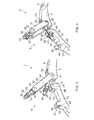
Figure 5 is a partial perspective view of the circumferential clamp shown inFigure 1 showing the latching assembly partially latched; and -
Figure 6 is a partial perspective view of the circumferential clamp shown inFigure 1 showing the latching assembly fully latched. -
Figure 1 shows part of acircumferential clamp 2 comprising a clamping band 4 and a latching assembly 6. The latching assembly 6 is shown fully latched. The clamping band 4 is shown only in part. It will be appreciated that the clamping band 4 extends in a complete loop, thereby defining a longitudinal axis about which the clamping band 4 clamps. - The clamping band 4 has two oppositely disposed first and second
circumferential ends - The latching assembly 6 comprises a
first latching device 12 and asecond latching device 14. - The
first latching device 12 comprises afirst eyebolt 16 having an eye 18 (not visible) at one end, a threadedsection 20 towards the other end and a threadedfastener 22 having a non-circular profile, for example a nut, engaged with the threadedsection 20. The lengthwise axis of thefirst eyebolt 16 defines the lengthwise axis of thefirst latching device 12. Thefirst latching device 12 further comprises asemi-cylindrical washer 24 having a convex surface and a flat surface (for example a barrel-type washer such as a saddle washer) arranged about the shank of theeyebolt 18 between the threadedfastener 22 and theeye 18. - The
first latching device 12 is secured to the firstcircumferential end 8 by a clevis arrangement comprising apin 21 which extends across arecess 23 in the firstcircumferential end 8 of the clamping band 4 and through theeye 18 of thefirst eyebolt 16. Thepin 21 extends through the walls of therecess 23 and in a direction which is parallel to the longitudinal axis of the clamping band 4. Thepin 21 can rotate with respect to the walls of therecess 23 and theeyebolt 16. Thepin 21 is held in place by circlips, crimped washers, swaged ends, steps or other suitable means. The clevis arrangement permits thefirst latching device 12 to pivot in a plane which is perpendicular to the longitudinal axis of the clamping band 4. - The
second latching device 14 comprises two parallelelongate links 26 connecting asecond eyebolt 28 to the firstcircumferential end 8, a second threaded fastener and a secondsemi-cylindrical washer 36. - Each
link 26 is secured to the respective ends of thepin 21 which extend through, and protrude from, the walls of therecess 23. Thelinks 26 are therefore pivotally connected to the firstcircumferential end 8 on opposite sides of the clamping band 4. Thelinks 26 are arranged to pivot independently of thefirst latching device 12 in respective planes that are parallel to the plane in which thefirst latching device 12 pivots. - The
second eyebolt 28 is secured to the free ends of thelinks 26 by a further clevis arrangement comprising asecond pin 31 passing through the free ends of thelinks 26 and an eye 30 (not visible) of thesecond eyebolt 28. Thepin 31 can rotate with respect to thelinks 26. Thepin 31 is held in place by means similar to that used for thepin 21. Thesecond eyebolt 28 is pivotable about thepin 31 with respect to thelinks 26.Spacers 33 are disposed between thelinks 26 and theeyebolt 28 to centralise theeyebolt 28 between thelinks 26. - The
second eyebolt 28 has a threaded section 32 (not visible) towards the end opposite theeye 30 and a threadedfastener 34 having a non-circular profile, for example a nut, is engaged with the threadedsection 32. Thesemi-cylindrical washer 36 is similar to that of thefirst fastening device 12, and is arranged about the shank of the bolt between the threadedfastener 34 and theeye 30. - The
second latching device 14 has a lengthwise axis which is defined midway between thelinks 26 and lies parallel to thelinks 26. The lengthwise axis of thesecond latching device 14 intersects the pivot axis defined by thepin 21. In the latched configuration ofFigure 1 , the lengthwise axis of thesecond eyebolt 28 coincides with the lengthwise axis of thesecond latching device 14. - The second
circumferential end 10 of the clamping band 4 has first and secondengaging portions Respective slots engaging portions slots respective eyebolts - As shown in
Figure 4 , eachengaging portion surfaces slots surfaces circumferential end 10. The concave bearingsurfaces second seats cylindrical washers second latching devices - Latching of the
circumferential clamp 2 is described as follows with reference toFigures 4 to 6 . -
Figure 4 shows the latching assembly 6 unlatched. Both the first andsecond latching devices circumferential end 10 and are shown pivoted outwardly away from the clamping band 4. The threadedfasteners sections eyebolts eyes fasteners semi-cylindrical washers engaging portions - The latching assembly 6 is partially latched by pivoting the
first latching device 12 towards the secondcircumferential end 10 of the clamping band 4. The threadedfastener 22 and thesemi-cylindrical washer 24 pass over the firstengaging portion 38 so that the shank of theeyebolt 16 lies along theslot 42 through the firstengaging portion 38. The lengthwise axis of thefirst latching device 12 is tangential to the clamping band 4. A socket is then placed over the threadedfastener 22 and used to wind thefastener 22 along the threadedsection 20 towards theeye 18 thereby tightening the threadedfastener 22 and thesemi-cylindrical washer 24 against thefirst seat 50. Thefirst latching device 14 thus secures the first and second circumferential ends 10 together. The threadedfastener 22 is tightened to clamp the clamping ring 4. The latching assembly 6 is shown inFigure 5 with thefirst latching device 12 securing the first and second circumferential ends 8, 10 together. - Once the
first latching device 12 has been latched, thesecond latching device 14 is pivoted towards the secondcircumferential end 10 of the clamping band 4. The threadedfastener 34 and thesemi-cylindrical washer 36 pass over the second engagingportion 40 so that the shank of thesecond eyebolt 28 lies along theslot 44 through the second engagingportion 40. Thelinks 26 extend each side of thefirst latching device 12 and each side of the first engagingportion 38. The lengthwise axis of thesecond latching device 14 is tangential to the clamping band 4 and intersects the lengthwise axis of thefirst latching device 12. The angle of intersection is small, for example between 0 and 20 degrees, and preferably no greater than 10 degrees, for example no greater than 5 degrees. The lengthwise axes of the first andsecond latching devices second latching devices first latching device 12 is disposed between thelinks 26 and the eye-end of thesecond eyebolt 28 obstructs access to the end of thesecond eyebolt 28. A socket is placed over the threadedfastener 22 and used to wind the threadedfastener 34 along the threadedsection 20 of thesecond eyebolt 28 to tighten the threadedfastener 34 and thesemi-cylindrical washer 36 against thesecond seat 52. Thesecond latching device 14 thus further secures the first and second circumferential ends 8, 10 together. The latching assembly 6 is shown inFigure 6 with the first andsecond latching devices Figure 1 . - Coincident, or intersecting, lengthwise axes of the first and
second latching devices devices latching devices first latching device 12 within thesecond latching device 14, the amount of radial space occupied by the latching assembly 6 is reduced. Consequently, the size of the portion of the clamping band 4 to which thelatching devices - Once the
second latching device 14 has been latched, access to the threadedfastener 22 is obstructed by thelinks 26 of thesecond latching device 14 and the end of thesecond eyebolt 28 which is secured to thelinks 26. Consequently, when both latchingdevices fastener 22 of thefirst latching device 12 in order to further tighten thefastener 22. This is particularly advantageous for latching devices which must be fastened in a predetermined sequence, for example when thefirst latching device 12 is a redundant latching device which should not be tightened after the second latching device has been tightened. - It will be appreciated that the latching
devices latching devices devices - More than one latching device 6 may be provided about the clamping band 4. These may be angularly offset from each other about the longitudinal axis of the clamping band 4.
- The circumferential clamp may, for example, comprise a V-coupling in accordance with SAE AS1895. Failsafe links may also be incorporated. These may be disposed between each of the threaded
fasteners cylindrical washers - A variant of the described embodiments comprises
links 26 pivotally connected to the firstcircumferential end 8 of the clamping band 4 by a separate clevis arrangement. Separate clevises provide redundancy in the event of failure of one of the clevises and can be used to provide a separate pivot for thesecond latching device 14. - The pivot of the
second latching device 14 may be disposed fore or aft of the pivot of thefirst latching device 12. The first andsecond latching devices portions - It will be appreciated that although the latching assembly has been described as being used to secure ends of a clamping band together, the latching assembly would be suitable for latching other types of components together, particularly where a compact latch is required or where over-stressing through alternate re-tightening of latching devices is to be avoided.
Claims (6)
- A circumferential clamp (2) comprising a clamping band (4) having oppositely disposed circumferential ends (8, 10) and a latching assembly (6) for securing the ends (8, 10) together, the latching assembly (6) comprising first and second latching devices (12, 14), each of which comprises an elongate element (16, 26, 28) which is pivotably mounted on the clamping band (4) adjacent one of the ends (8, 10) and is engageable with the clamping band (4) adjacent the other end to latch the ends (8, 10) together, the lengthwise axes of the elongate elements (16, 26, 28) lying in, or intersecting, a common plane tangential to the clamping band (4), wherein the elongate elements (16, 26, 28) of the first and second latching devices (12, 14) are mounted on the clamping band (4) to pivot about a common axis and the second latching device (14) obstructs access to the first latching device (12) when the ends (8, 10) of the clamping band (4) are latched together by the first and second latching devices (12, 14).
- A circumferential clamp as claimed in claim 1, wherein the lengthwise axes of the elongate elements (16, 26, 28) are coincident with, or intersect, each other.
- A circumferential clamp as claimed in any one of the preceding claims, wherein the second latching device (14) comprises at least one linkage (26) which is offset from the lengthwise axis of the second latching device (14) so as to accommodate the first latching device (12).
- A circumferential clamp as claimed in claim 3, wherein the or each linkage (26) comprises a plurality of stacked plate links (26), each plate link (26) extending parallel to the lengthwise axis of the second latching device (14).
- A circumferential clamp as claimed in claim 4, wherein the first latching device (12) is disposed between plate links (26) of the linkage when the ends (8, 10) of the clamping band (4) are latched together by the first and second latching devices (12, 14).
- A latching assembly (6) for securing two components (8, 10) together, the latching assembly (6) comprising first and second latching devices (12, 14), each of which comprises an elongate element (16, 26, 28) which is pivotably mounted to one of the components (8, 10) and is engagable with the other component to latch the components (8, 10) together, the lengthwise axes of the elongate elements (16, 26, 28) being coincident with, or intersecting, each other, wherein the elongate elements (16, 26, 28) of the first and second latching devices (12, 14) are mounted on the clamping band (4) to pivot about a common axis and the second latching (14) device obstructs access to the first latching device (12) when the first and second component (8, 10) are latched together by the first and second latching devices (12, 14).
Applications Claiming Priority (1)
| Application Number | Priority Date | Filing Date | Title |
|---|---|---|---|
| GBGB1016016.6A GB201016016D0 (en) | 2010-09-24 | 2010-09-24 | Circumferential clamp and latching assembly |
Publications (2)
| Publication Number | Publication Date |
|---|---|
| EP2434193A2 true EP2434193A2 (en) | 2012-03-28 |
| EP2434193A3 EP2434193A3 (en) | 2017-05-10 |
Family
ID=43127851
Family Applications (1)
| Application Number | Title | Priority Date | Filing Date |
|---|---|---|---|
| EP11178579.6A Withdrawn EP2434193A3 (en) | 2010-09-24 | 2011-08-24 | Circumferential clamp and latching assembly |
Country Status (3)
| Country | Link |
|---|---|
| US (1) | US8661626B2 (en) |
| EP (1) | EP2434193A3 (en) |
| GB (1) | GB201016016D0 (en) |
Cited By (1)
| Publication number | Priority date | Publication date | Assignee | Title |
|---|---|---|---|---|
| FR2994711A1 (en) * | 2012-08-27 | 2014-02-28 | Aircelle Sa | ASSEMBLY FOR HOLDING THE INTERFACE OF A FRONT FRAME OF A NACELLE AND A TURBOJET CARTER |
Families Citing this family (2)
| Publication number | Priority date | Publication date | Assignee | Title |
|---|---|---|---|---|
| GB2532995B (en) * | 2014-12-05 | 2016-12-28 | Aes Eng Ltd | Modular pipe clamp |
| US10422455B1 (en) * | 2015-04-08 | 2019-09-24 | Terminal Manufacturing Co., LLC | Pipe attachment clamp |
Family Cites Families (29)
| Publication number | Priority date | Publication date | Assignee | Title |
|---|---|---|---|---|
| US1687340A (en) * | 1925-08-12 | 1928-10-09 | Fisk Rubber Co | Beveling and sealing clamp |
| US2189172A (en) * | 1939-03-10 | 1940-02-06 | Charles E Hathorn | Clamp |
| US2635319A (en) * | 1951-09-08 | 1953-04-21 | Fenton M Davison | Band clamp |
| US2752174A (en) * | 1953-06-16 | 1956-06-26 | Victaulic Co Of America | Hinged pipe coupling and method of making the same |
| US2775806A (en) * | 1953-09-09 | 1957-01-01 | Kac Ltd | Adjustable girth clamping ring |
| US3164401A (en) * | 1961-02-20 | 1965-01-05 | Pratt Co Henry | Expansion joint |
| US3233922A (en) * | 1963-07-29 | 1966-02-08 | Cast Iron Soil Pipe Inst | Pipe joint |
| US3267547A (en) * | 1964-02-10 | 1966-08-23 | Smith Blair Inc | Pipe clamp |
| US3359017A (en) * | 1967-03-01 | 1967-12-19 | Ideal Corp | Pipe coupling of corrugated shield type |
| GB1249499A (en) * | 1969-04-29 | 1971-10-13 | Avica Equip | Improvements in and relating to circular clamps |
| AT316234B (en) * | 1971-12-23 | 1974-06-25 | Hawle Erwin | Tapping clamp |
| US3848638A (en) * | 1973-05-24 | 1974-11-19 | Dresser Ind | Pipe repair clamp |
| US4123095A (en) * | 1977-06-30 | 1978-10-31 | Hansted Corporation | Pipe clamp having an overcenter toggle |
| GB2050491B (en) | 1978-12-05 | 1982-08-25 | Smith & Johnson Keighley Ltd | Fail safe clamp |
| US4381020A (en) * | 1981-07-30 | 1983-04-26 | Mueller Co. | Single and multiple section pipe repair or service clamps |
| US4739542A (en) * | 1987-02-09 | 1988-04-26 | Aeroquip Corporation | Safety coupling clamp |
| US4919453A (en) * | 1987-06-16 | 1990-04-24 | Eg&G Pressure Science, Inc. | Low profile V-coupling |
| CH681318A5 (en) | 1990-03-20 | 1993-02-26 | Straub Federnfabrik | |
| FR2670844B1 (en) | 1990-12-21 | 1993-04-16 | Aerospatiale | REMOTE RELEASE TENSIONING MECHANISM OF A FLEXIBLE MEMBER SUCH AS A STRAP AND DEVICE FOR RIGID CONNECTION OF TWO MECHANICAL ASSEMBLIES USING SUCH A MECHANISM. |
| GB2253020B (en) | 1991-02-02 | 1994-09-28 | Connectors | Improvements relating to toggle mechanism clamps |
| US5454606A (en) * | 1993-02-04 | 1995-10-03 | Voss Industries, Inc. | V-retainer coupling assembly construction which prevents incorrect installation with reduced width slot |
| FR2710716B1 (en) * | 1993-09-28 | 1995-12-22 | Framatome Sa | Hose clamp of two tubular parts having a safety locking device and use. |
| US5509702A (en) * | 1994-08-23 | 1996-04-23 | Eg&G Pressure Science, Inc. | Low distortion pipe coupling device |
| US5522625A (en) * | 1994-11-29 | 1996-06-04 | Hoechst Marion Roussel, Inc. | Coupling device |
| US6796004B2 (en) * | 2001-09-14 | 2004-09-28 | Donaldson Company, Inc. | Exhaust system clamp |
| DE102005017368A1 (en) * | 2005-03-08 | 2006-09-21 | Metu Meinig Aktiengesellschaft | Open clamping ring with screw lock |
| AU2008229788B2 (en) * | 2008-10-03 | 2015-10-22 | Wang Components Pty Ltd | Pipe clamp |
| FR2943746B1 (en) | 2009-03-27 | 2011-06-03 | Hutchinson | TIGHTENING COLLAR AND FLAT ROLLING DEVICE INCORPORATING IT |
| GB201015827D0 (en) * | 2010-09-22 | 2010-10-27 | Rolls Royce Plc | An assembly comprising first and second fasteners and a baulking element |
-
2010
- 2010-09-24 GB GBGB1016016.6A patent/GB201016016D0/en not_active Ceased
-
2011
- 2011-08-24 US US13/216,620 patent/US8661626B2/en not_active Expired - Fee Related
- 2011-08-24 EP EP11178579.6A patent/EP2434193A3/en not_active Withdrawn
Non-Patent Citations (1)
| Title |
|---|
| None |
Cited By (5)
| Publication number | Priority date | Publication date | Assignee | Title |
|---|---|---|---|---|
| FR2994711A1 (en) * | 2012-08-27 | 2014-02-28 | Aircelle Sa | ASSEMBLY FOR HOLDING THE INTERFACE OF A FRONT FRAME OF A NACELLE AND A TURBOJET CARTER |
| WO2014033398A1 (en) * | 2012-08-27 | 2014-03-06 | Aircelle | Assembly for holding the interface of a front frame of a nacelle and a turbojet casing |
| CN104603401A (en) * | 2012-08-27 | 2015-05-06 | 埃尔塞乐公司 | Assembly for holding interface of front frame of nacelle and turbojet casing |
| CN104603401B (en) * | 2012-08-27 | 2016-04-13 | 埃尔塞乐公司 | For the assembly of fixing cabin front baffle and turbojet engine shell interfaces |
| US9388769B2 (en) | 2012-08-27 | 2016-07-12 | Aircelle | Assembly for holding the interface of a front frame of a nacelle and a turbojet engine casing |
Also Published As
| Publication number | Publication date |
|---|---|
| US8661626B2 (en) | 2014-03-04 |
| EP2434193A3 (en) | 2017-05-10 |
| US20120073091A1 (en) | 2012-03-29 |
| GB201016016D0 (en) | 2010-11-10 |
Similar Documents
| Publication | Publication Date | Title |
|---|---|---|
| CN110116813B (en) | Assembly for aircraft engine mount and aircraft | |
| EP2669545B1 (en) | Securing mechanism for shackle | |
| RU2472982C2 (en) | Improved nut and bolt | |
| US8454056B2 (en) | Double strap coupling apparatus | |
| EP1765638B1 (en) | Load binder | |
| US20090218777A1 (en) | Tie rod assembly | |
| US7749035B2 (en) | Buoyancy clamp and method of application | |
| US8342770B2 (en) | Coupling device intended to connect first and second elements which are hinged with respect to one another | |
| US8661626B2 (en) | Circumferential clamp and latching assembly | |
| EP1716339B1 (en) | Clamping apparatus and method | |
| CN102753875B (en) | Coupling clamping system and method | |
| FR2847623A1 (en) | Two-piece washer for minimizing bending of bolt, has convex and concave surfaces of outer and inner annular washer elements which contact with each other and move relative to each other so that respective axes assume non-coaxial positions | |
| US11208215B2 (en) | Method for mounting an aircraft pylon | |
| US20190161198A1 (en) | Pivoting axis for an aircraft engine attachment | |
| US8465060B2 (en) | Assembly comprising first and second fasteners and a baulking element | |
| KR100853326B1 (en) | Shaft coupling | |
| US10012258B2 (en) | Locking device for a threaded fastener | |
| EP3685051A1 (en) | Clamp assembly | |
| US20120177459A1 (en) | System and method for fixedly connecting sheets | |
| CN108370105B (en) | Electrical connector and connecting method | |
| US7900430B1 (en) | Quick connect coupling link | |
| US20150137505A1 (en) | Header Tethering System | |
| US10294980B2 (en) | Control cable quick disconnect | |
| WO2017175173A1 (en) | Bend radius device for flexible tube | |
| JP2007053834A (en) | Strain clamp reinforcement device and strain clamp equipped with reinforcement device |
Legal Events
| Date | Code | Title | Description |
|---|---|---|---|
| PUAI | Public reference made under article 153(3) epc to a published international application that has entered the european phase |
Free format text: ORIGINAL CODE: 0009012 |
|
| AK | Designated contracting states |
Kind code of ref document: A2 Designated state(s): AL AT BE BG CH CY CZ DE DK EE ES FI FR GB GR HR HU IE IS IT LI LT LU LV MC MK MT NL NO PL PT RO RS SE SI SK SM TR |
|
| AX | Request for extension of the european patent |
Extension state: BA ME |
|
| RAP1 | Party data changed (applicant data changed or rights of an application transferred) |
Owner name: ROLLS-ROYCE PLC |
|
| PUAL | Search report despatched |
Free format text: ORIGINAL CODE: 0009013 |
|
| AK | Designated contracting states |
Kind code of ref document: A3 Designated state(s): AL AT BE BG CH CY CZ DE DK EE ES FI FR GB GR HR HU IE IS IT LI LT LU LV MC MK MT NL NO PL PT RO RS SE SI SK SM TR |
|
| AX | Request for extension of the european patent |
Extension state: BA ME |
|
| RIC1 | Information provided on ipc code assigned before grant |
Ipc: F16L 23/10 20060101AFI20170401BHEP |
|
| STAA | Information on the status of an ep patent application or granted ep patent |
Free format text: STATUS: REQUEST FOR EXAMINATION WAS MADE |
|
| 17P | Request for examination filed |
Effective date: 20170811 |
|
| RBV | Designated contracting states (corrected) |
Designated state(s): AL AT BE BG CH CY CZ DE DK EE ES FI FR GB GR HR HU IE IS IT LI LT LU LV MC MK MT NL NO PL PT RO RS SE SI SK SM TR |
|
| GRAP | Despatch of communication of intention to grant a patent |
Free format text: ORIGINAL CODE: EPIDOSNIGR1 |
|
| STAA | Information on the status of an ep patent application or granted ep patent |
Free format text: STATUS: GRANT OF PATENT IS INTENDED |
|
| INTG | Intention to grant announced |
Effective date: 20180904 |
|
| STAA | Information on the status of an ep patent application or granted ep patent |
Free format text: STATUS: THE APPLICATION IS DEEMED TO BE WITHDRAWN |
|
| 18D | Application deemed to be withdrawn |
Effective date: 20190115 |