EP2434096A2 - Gasturbinenschaufel mit einem Leitungssockel - Google Patents
Gasturbinenschaufel mit einem Leitungssockel Download PDFInfo
- Publication number
- EP2434096A2 EP2434096A2 EP11182897A EP11182897A EP2434096A2 EP 2434096 A2 EP2434096 A2 EP 2434096A2 EP 11182897 A EP11182897 A EP 11182897A EP 11182897 A EP11182897 A EP 11182897A EP 2434096 A2 EP2434096 A2 EP 2434096A2
- Authority
- EP
- European Patent Office
- Prior art keywords
- leading edge
- airfoil
- recited
- side wall
- rib
- Prior art date
- Legal status (The legal status is an assumption and is not a legal conclusion. Google has not performed a legal analysis and makes no representation as to the accuracy of the status listed.)
- Granted
Links
- NJPPVKZQTLUDBO-UHFFFAOYSA-N novaluron Chemical compound C1=C(Cl)C(OC(F)(F)C(OC(F)(F)F)F)=CC=C1NC(=O)NC(=O)C1=C(F)C=CC=C1F NJPPVKZQTLUDBO-UHFFFAOYSA-N 0.000 title claims abstract description 11
- 238000001816 cooling Methods 0.000 claims description 27
- 239000007789 gas Substances 0.000 description 13
- 239000011162 core material Substances 0.000 description 12
- 229920001169 thermoplastic Polymers 0.000 description 5
- 239000004416 thermosoftening plastic Substances 0.000 description 5
- 238000002485 combustion reaction Methods 0.000 description 4
- 230000008901 benefit Effects 0.000 description 3
- 230000008859 change Effects 0.000 description 2
- 239000000567 combustion gas Substances 0.000 description 2
- 230000000694 effects Effects 0.000 description 2
- 239000002184 metal Substances 0.000 description 2
- 230000009467 reduction Effects 0.000 description 2
- 235000017060 Arachis glabrata Nutrition 0.000 description 1
- 241001553178 Arachis glabrata Species 0.000 description 1
- 235000010777 Arachis hypogaea Nutrition 0.000 description 1
- 235000018262 Arachis monticola Nutrition 0.000 description 1
- 239000002826 coolant Substances 0.000 description 1
- 239000000284 extract Substances 0.000 description 1
- 239000000446 fuel Substances 0.000 description 1
- 238000004519 manufacturing process Methods 0.000 description 1
- 238000000034 method Methods 0.000 description 1
- 238000012986 modification Methods 0.000 description 1
- 230000004048 modification Effects 0.000 description 1
- 230000003647 oxidation Effects 0.000 description 1
- 238000007254 oxidation reaction Methods 0.000 description 1
- 235000020232 peanut Nutrition 0.000 description 1
- 230000008569 process Effects 0.000 description 1
- 230000003068 static effect Effects 0.000 description 1
Images


Classifications
-
- F—MECHANICAL ENGINEERING; LIGHTING; HEATING; WEAPONS; BLASTING
- F01—MACHINES OR ENGINES IN GENERAL; ENGINE PLANTS IN GENERAL; STEAM ENGINES
- F01D—NON-POSITIVE DISPLACEMENT MACHINES OR ENGINES, e.g. STEAM TURBINES
- F01D5/00—Blades; Blade-carrying members; Heating, heat-insulating, cooling or antivibration means on the blades or the members
- F01D5/12—Blades
- F01D5/14—Form or construction
- F01D5/18—Hollow blades, i.e. blades with cooling or heating channels or cavities; Heating, heat-insulating or cooling means on blades
- F01D5/187—Convection cooling
-
- F—MECHANICAL ENGINEERING; LIGHTING; HEATING; WEAPONS; BLASTING
- F05—INDEXING SCHEMES RELATING TO ENGINES OR PUMPS IN VARIOUS SUBCLASSES OF CLASSES F01-F04
- F05D—INDEXING SCHEME FOR ASPECTS RELATING TO NON-POSITIVE-DISPLACEMENT MACHINES OR ENGINES, GAS-TURBINES OR JET-PROPULSION PLANTS
- F05D2240/00—Components
- F05D2240/10—Stators
- F05D2240/12—Fluid guiding means, e.g. vanes
- F05D2240/121—Fluid guiding means, e.g. vanes related to the leading edge of a stator vane
-
- F—MECHANICAL ENGINEERING; LIGHTING; HEATING; WEAPONS; BLASTING
- F05—INDEXING SCHEMES RELATING TO ENGINES OR PUMPS IN VARIOUS SUBCLASSES OF CLASSES F01-F04
- F05D—INDEXING SCHEME FOR ASPECTS RELATING TO NON-POSITIVE-DISPLACEMENT MACHINES OR ENGINES, GAS-TURBINES OR JET-PROPULSION PLANTS
- F05D2260/00—Function
- F05D2260/20—Heat transfer, e.g. cooling
- F05D2260/201—Heat transfer, e.g. cooling by impingement of a fluid
-
- F—MECHANICAL ENGINEERING; LIGHTING; HEATING; WEAPONS; BLASTING
- F05—INDEXING SCHEMES RELATING TO ENGINES OR PUMPS IN VARIOUS SUBCLASSES OF CLASSES F01-F04
- F05D—INDEXING SCHEME FOR ASPECTS RELATING TO NON-POSITIVE-DISPLACEMENT MACHINES OR ENGINES, GAS-TURBINES OR JET-PROPULSION PLANTS
- F05D2260/00—Function
- F05D2260/20—Heat transfer, e.g. cooling
- F05D2260/202—Heat transfer, e.g. cooling by film cooling
-
- F—MECHANICAL ENGINEERING; LIGHTING; HEATING; WEAPONS; BLASTING
- F05—INDEXING SCHEMES RELATING TO ENGINES OR PUMPS IN VARIOUS SUBCLASSES OF CLASSES F01-F04
- F05D—INDEXING SCHEME FOR ASPECTS RELATING TO NON-POSITIVE-DISPLACEMENT MACHINES OR ENGINES, GAS-TURBINES OR JET-PROPULSION PLANTS
- F05D2260/00—Function
- F05D2260/20—Heat transfer, e.g. cooling
- F05D2260/221—Improvement of heat transfer
- F05D2260/2214—Improvement of heat transfer by increasing the heat transfer surface
Definitions
- the present disclosure relates to a gas turbine engine, and more particularly to an airfoil cooling arrangement.
- a gas turbine engine includes a compressor section that compresses air then channels the compressed air to a combustor section wherein the compressed airflow is mixed with fuel and ignited to generate high temperature combustion gases.
- the combustion core gases flow downstream through a turbine section which extracts energy therefrom to power the compressor section and a fan section. Since the combustion core gases are at a high temperature, turbine vanes and turbine blades within the turbine section may have relatively high heat loads at the leading edges.
- An airfoil for a gas turbine engine includes a pressure side wall and a suction side wall which define a leading edge cavity and a forward cavity between the pressure side wall and the suction side wall, with the leading edge cavity at least partially defined by a leading edge wall which extends between the pressure side wall and the suction side wall.
- a rib between the pressure side wall and the suction side wall separates the forward cavity and the leading edge cavity.
- a pedestal extends between the leading edge wall and the rib.
- An airfoil for a gas turbine engine includes a multiple of pedestals which extend between a leading edge and a rib, the multiple of pedestals arrayed along a length of the airfoil between a first end portion and a second end portion.
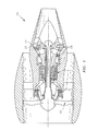
- Figure 1 schematically illustrates a gas turbine engine 10 which generally includes a fan section 12, a compressor section 14, a combustor section 16, and a turbine section 18. Within and aft of the combustor section 16, engine components are typically cooled due to intense temperature of the combustion core gases. While a two spool high bypass turbofan engine is schematically illustrated in the disclosed non-limiting embodiment, it should be understood that the disclosure is applicable to other gas turbine engine configurations.
- the cooling airflow passes through at least one cooling circuit flow path 26 ( Figure 2 ) to transfer thermal energy from the component to the cooling airflow.
- Each cooling circuit flow path 26 may be disposed in any component that requires cooling, and in most cases the component receives cooling airflow therethrough as the external surface thereof is exposed to combustion core gases.
- the cooling circuit flow path 26 will be described herein as being disposed within a portion of an airfoil 32 such as that of a stator vane 24 or rotor blade 22. It should be understood, however, that the cooling circuit flow path 26 is not limited to these applications and may be utilized within other areas such as liners, seals, and other structures with stagnation regions exposed to high temperature core gas flow.
- the cooling circuit flow path 26 communicates with a multiple of cavities, for example 34A-34B shown in Figure 3 , formed within the airfoil 32.
- the multiple of cavities 34A-34B direct cooling airflow which may include air received from the compressor section into high temperature areas of the airfoil 32.
- the airfoil 32 is defined by an outer airfoil wall surface 40 between a leading edge 36 and a trailing edge 42.
- the outer airfoil wall surface 40 typically has a generally concave shaped portion forming a pressure side 40P and a generally convex shaped portion forming a suction side 40S which are connected by a leading edge wall 40L at the leading edge 36.
- the outer airfoil wall surface 40 is longitudinally defined to span a first end portion 46 and a second end portion 48.
- the end portions 46, 48 may include features to mount the airfoil to other structures such as engine static structure or rotor disk.
- the end portions 46, 48 for a vane may include outer vane platforms and for a blade may include an attachment section and a blade tip. It should be understood that various component arrangement may likewise be utilized with the present invention.
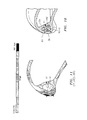
- the forward cavity 34A is generally defined by a first rib 54 just aft of the leading edge 36.
- the first rib 54 separates the forward cavity 34A from a leading edge cavity 56 defined at least partially by the outer airfoil wall surface 40 and often referred to as a "peanut" cavity.
- the first rib 54 may, for example, at least partially define an impingement leading edge 62 ( Figure 4 ) or a radial flow leading edge 64 ( Figure 5 ) which may span a portion of or the entire length of the airfoil 32. That is, the pedestals 60 may be specifically located along the entire airfoil 32 span or a select portion or portions thereof
- the leading edge cavity 56 includes the multiple of pedestals 60 which are transverse to and extend between the leading edge 36 and the first rib 54. It should be understood that any number of pedestals 60 may be so positioned.
- the pedestals 60 provide an additional thermal conductive path along a conduction path axis H ( Figure 6 ) from the leading edge 36 to the first rib 54 to reduce the temperature of the leading edge 36 as the leading edge 36 may otherwise be hundreds of degrees hotter than the pressure side 40P and suction side 40S of the airfoil 32 due to higher external heat transfer coefficients at the stagnation region S ( Figure 7 ). It should be understood that the stagnation region S is a region within which the combustion gas flow Mach number may be relatively low such that a temperature concentration occurs.
- the first rib 54 may define a multiple of cooling holes 66 which communicate a cooling flow from the forward cavity 34A into the leading edge cavity 56 through the first rib 54 then out through a multiple of leading edge cooling holes 68. That is, the cooling flow is communicated generally along the pedestals 60.
- the cooling flow from within the leading edge cavity 56 passes transverse to the pedestals 60 and out through a multiple of leading edge cooling holes 70. It should be understood that various such cooling schemes will benefit from the pedestals 60.
- the pedestals 60 reduce leading edge 36 temperatures mainly from the enhanced conduction effects of the pedestals 60 from the leading edge 36 to the first rib 54 ( Figures 8 and 9 ).
- a portion of the metal temperature reduction is achieved by the enhancement of the internal heat transfer coefficient as coolant flow passes over the pedestals 60.
- the lower temperature at the stagnation region beneficially results in, for example, a higher oxidation, local creep, and Thermal Mechanical Fatigue (TMF) capability.
- TMF Thermal Mechanical Fatigue
- the pedestals 60 may be selectively oriented at a multiple of different angles in the leading edge cavity 56 to achieve the desired thermal reduction effect. That is, the pedestals 60-1, 60-2 may be aligned along conduction path axes H1, H2 ( Figure 10 ) which extend into the highest temperature areas in the stagnation region of the leading edge 36 ( Figure 11 ) to facilitate a more direct heat transfer from the leading edge 36 to the first rib 54. It should be understood that the axes H1, H2 may change along the span of the airfoil 32. The relative positions of the pedestals 60-1, 60-2 may thereby also change along the span to con-espand therewith.
- the manufacture of the pedestals 60 may be achieved by a proprietary Fugitive Core Process which uses thermoplastic inserts to create a one piece core with multiple pull angles as developed by Alcoa Howmet of Cleveland Ohio USA.
- a proprietary Fugitive Core Process which uses thermoplastic inserts to create a one piece core with multiple pull angles as developed by Alcoa Howmet of Cleveland Ohio USA.
- sacrificial thermoplastic pieces make up the rib and leading edge pedestals; the thermoplastic pieces are assembled into the core die and core material is injected around the thermoplastic pieces; the thermoplastic pieces are melted, leaving voids in finished core; and metal fill voids in core to form pedestals in the finished part.
Landscapes
- Engineering & Computer Science (AREA)
- Mechanical Engineering (AREA)
- General Engineering & Computer Science (AREA)
- Turbine Rotor Nozzle Sealing (AREA)
Applications Claiming Priority (1)
| Application Number | Priority Date | Filing Date | Title |
|---|---|---|---|
| US12/892,056 US20120076660A1 (en) | 2010-09-28 | 2010-09-28 | Conduction pedestals for a gas turbine engine airfoil |
Publications (3)
| Publication Number | Publication Date |
|---|---|
| EP2434096A2 true EP2434096A2 (de) | 2012-03-28 |
| EP2434096A3 EP2434096A3 (de) | 2015-04-29 |
| EP2434096B1 EP2434096B1 (de) | 2016-08-03 |
Family
ID=44719513
Family Applications (1)
| Application Number | Title | Priority Date | Filing Date |
|---|---|---|---|
| EP11182897.6A Active EP2434096B1 (de) | 2010-09-28 | 2011-09-27 | Gasturbinenschaufel mit einem Leitungssockel |
Country Status (2)
| Country | Link |
|---|---|
| US (1) | US20120076660A1 (de) |
| EP (1) | EP2434096B1 (de) |
Cited By (2)
| Publication number | Priority date | Publication date | Assignee | Title |
|---|---|---|---|---|
| WO2018153796A1 (en) * | 2017-02-24 | 2018-08-30 | Siemens Aktiengesellschaft | A turbomachine blade or vane having a cooling channel with a criss-cross arrangement of pins |
| EP3594448B1 (de) * | 2018-07-13 | 2022-11-02 | Honeywell International Inc. | Schaufelblatt mit konvektiver vorderkantenkühlung |
Families Citing this family (11)
| Publication number | Priority date | Publication date | Assignee | Title |
|---|---|---|---|---|
| EP2436884A1 (de) * | 2010-09-29 | 2012-04-04 | Siemens Aktiengesellschaft | Turbinenanordnung und Gasturbinenmotor |
| US9759072B2 (en) | 2012-08-30 | 2017-09-12 | United Technologies Corporation | Gas turbine engine airfoil cooling circuit arrangement |
| US9115590B2 (en) | 2012-09-26 | 2015-08-25 | United Technologies Corporation | Gas turbine engine airfoil cooling circuit |
| US10427213B2 (en) | 2013-07-31 | 2019-10-01 | General Electric Company | Turbine blade with sectioned pins and method of making same |
| US9695696B2 (en) | 2013-07-31 | 2017-07-04 | General Electric Company | Turbine blade with sectioned pins |
| US20150196489A1 (en) * | 2013-12-18 | 2015-07-16 | Massachusetts Institute Of Technology | Polymer matrices for controlling crystallization |
| US20160230566A1 (en) * | 2015-02-11 | 2016-08-11 | United Technologies Corporation | Angled pedestals for cooling channels |
| FR3057295B1 (fr) * | 2016-10-12 | 2020-12-11 | Safran Aircraft Engines | Aube comprenant une plate-forme et une pale assemblees |
| US10787932B2 (en) | 2018-07-13 | 2020-09-29 | Honeywell International Inc. | Turbine blade with dust tolerant cooling system |
| US10989067B2 (en) * | 2018-07-13 | 2021-04-27 | Honeywell International Inc. | Turbine vane with dust tolerant cooling system |
| US11230929B2 (en) | 2019-11-05 | 2022-01-25 | Honeywell International Inc. | Turbine component with dust tolerant cooling system |
Family Cites Families (8)
| Publication number | Priority date | Publication date | Assignee | Title |
|---|---|---|---|---|
| US4257737A (en) * | 1978-07-10 | 1981-03-24 | United Technologies Corporation | Cooled rotor blade |
| US5271715A (en) * | 1992-12-21 | 1993-12-21 | United Technologies Corporation | Cooled turbine blade |
| FR2765265B1 (fr) * | 1997-06-26 | 1999-08-20 | Snecma | Aubage refroidi par rampe helicoidale, par impact en cascade et par systeme a pontets dans une double peau |
| US7018176B2 (en) * | 2004-05-06 | 2006-03-28 | United Technologies Corporation | Cooled turbine airfoil |
| US7195458B2 (en) * | 2004-07-02 | 2007-03-27 | Siemens Power Generation, Inc. | Impingement cooling system for a turbine blade |
| EP1921269A1 (de) * | 2006-11-09 | 2008-05-14 | Siemens Aktiengesellschaft | Turbinenschaufel |
| GB0813839D0 (en) * | 2008-07-30 | 2008-09-03 | Rolls Royce Plc | An aerofoil and method for making an aerofoil |
| US9353631B2 (en) * | 2011-08-22 | 2016-05-31 | United Technologies Corporation | Gas turbine engine airfoil baffle |
-
2010
- 2010-09-28 US US12/892,056 patent/US20120076660A1/en not_active Abandoned
-
2011
- 2011-09-27 EP EP11182897.6A patent/EP2434096B1/de active Active
Non-Patent Citations (1)
| Title |
|---|
| None |
Cited By (2)
| Publication number | Priority date | Publication date | Assignee | Title |
|---|---|---|---|---|
| WO2018153796A1 (en) * | 2017-02-24 | 2018-08-30 | Siemens Aktiengesellschaft | A turbomachine blade or vane having a cooling channel with a criss-cross arrangement of pins |
| EP3594448B1 (de) * | 2018-07-13 | 2022-11-02 | Honeywell International Inc. | Schaufelblatt mit konvektiver vorderkantenkühlung |
Also Published As
| Publication number | Publication date |
|---|---|
| EP2434096B1 (de) | 2016-08-03 |
| EP2434096A3 (de) | 2015-04-29 |
| US20120076660A1 (en) | 2012-03-29 |
Similar Documents
| Publication | Publication Date | Title |
|---|---|---|
| EP2434096B1 (de) | Gasturbinenschaufel mit einem Leitungssockel | |
| US10301947B2 (en) | Gas turbine engine component cooling circuit | |
| US8562286B2 (en) | Dead ended bulbed rib geometry for a gas turbine engine | |
| US9458725B2 (en) | Method and system for providing cooling for turbine components | |
| US8157527B2 (en) | Airfoil with tapered radial cooling passage | |
| US7775768B2 (en) | Turbine component with axially spaced radially flowing microcircuit cooling channels | |
| US9863254B2 (en) | Turbine airfoil with local wall thickness control | |
| US7828515B1 (en) | Multiple piece turbine airfoil | |
| US8240975B1 (en) | Multiple staged compressor with last stage airfoil cooling | |
| EP2825732B1 (de) | Kühlkreis für gasturbinenmotorschaufel | |
| US7824150B1 (en) | Multiple piece turbine airfoil | |
| US20120207591A1 (en) | Cooling system having reduced mass pin fins for components in a gas turbine engine | |
| EP1088964A2 (de) | Schlitz zur Prallkühlung der Anströmkante einer Turbinenschaufel | |
| EP3043026B1 (de) | Hochauftriebschaufel und zugehöriges verfahren zum lenken von kühlluft | |
| US8303252B2 (en) | Airfoil with cooling passage providing variable heat transfer rate | |
| US10364683B2 (en) | Gas turbine engine component cooling passage turbulator | |
| US11982231B2 (en) | Hourglass airfoil cooling configuration | |
| US20160003053A1 (en) | Gas turbine engine component having transversely angled impingement ribs | |
| US20150110611A1 (en) | Airfoil cooling circuit and corresponding airfoil | |
| EP3273005A1 (de) | Luftgekühlte komponente für einen gasturbinenmotor | |
| EP3441568B1 (de) | Turbomaschinenprallkühleinsatz | |
| EP3650639A1 (de) | Abschirmung für eine turbinentriebwerksschaufel | |
| CN107091122B (zh) | 具有冷却的涡轮发动机翼型件 | |
| CN108779679B (zh) | 被冷却的涡轮叶片 | |
| US10830072B2 (en) | Turbomachine airfoil |
Legal Events
| Date | Code | Title | Description |
|---|---|---|---|
| PUAI | Public reference made under article 153(3) epc to a published international application that has entered the european phase |
Free format text: ORIGINAL CODE: 0009012 |
|
| AK | Designated contracting states |
Kind code of ref document: A2 Designated state(s): AL AT BE BG CH CY CZ DE DK EE ES FI FR GB GR HR HU IE IS IT LI LT LU LV MC MK MT NL NO PL PT RO RS SE SI SK SM TR |
|
| AX | Request for extension of the european patent |
Extension state: BA ME |
|
| PUAL | Search report despatched |
Free format text: ORIGINAL CODE: 0009013 |
|
| AK | Designated contracting states |
Kind code of ref document: A3 Designated state(s): AL AT BE BG CH CY CZ DE DK EE ES FI FR GB GR HR HU IE IS IT LI LT LU LV MC MK MT NL NO PL PT RO RS SE SI SK SM TR |
|
| AX | Request for extension of the european patent |
Extension state: BA ME |
|
| RIC1 | Information provided on ipc code assigned before grant |
Ipc: F01D 5/18 20060101AFI20150325BHEP |
|
| 17P | Request for examination filed |
Effective date: 20151029 |
|
| RBV | Designated contracting states (corrected) |
Designated state(s): AL AT BE BG CH CY CZ DE DK EE ES FI FR GB GR HR HU IE IS IT LI LT LU LV MC MK MT NL NO PL PT RO RS SE SI SK SM TR |
|
| GRAP | Despatch of communication of intention to grant a patent |
Free format text: ORIGINAL CODE: EPIDOSNIGR1 |
|
| INTG | Intention to grant announced |
Effective date: 20160215 |
|
| GRAS | Grant fee paid |
Free format text: ORIGINAL CODE: EPIDOSNIGR3 |
|
| GRAA | (expected) grant |
Free format text: ORIGINAL CODE: 0009210 |
|
| AK | Designated contracting states |
Kind code of ref document: B1 Designated state(s): AL AT BE BG CH CY CZ DE DK EE ES FI FR GB GR HR HU IE IS IT LI LT LU LV MC MK MT NL NO PL PT RO RS SE SI SK SM TR |
|
| REG | Reference to a national code |
Ref country code: GB Ref legal event code: FG4D |
|
| REG | Reference to a national code |
Ref country code: CH Ref legal event code: EP Ref country code: AT Ref legal event code: REF Ref document number: 817472 Country of ref document: AT Kind code of ref document: T Effective date: 20160815 |
|
| REG | Reference to a national code |
Ref country code: IE Ref legal event code: FG4D |
|
| REG | Reference to a national code |
Ref country code: DE Ref legal event code: R096 Ref document number: 602011028740 Country of ref document: DE |
|
| REG | Reference to a national code |
Ref country code: CH Ref legal event code: PCOW Free format text: NEW ADDRESS: 10 FARM SPRINGS RD., FARMINGTON, CT 06032 (US) |
|
| RAP2 | Party data changed (patent owner data changed or rights of a patent transferred) |
Owner name: UNITED TECHNOLOGIES CORPORATION |
|
| REG | Reference to a national code |
Ref country code: FR Ref legal event code: PLFP Year of fee payment: 6 |
|
| REG | Reference to a national code |
Ref country code: NL Ref legal event code: MP Effective date: 20160803 |
|
| REG | Reference to a national code |
Ref country code: LT Ref legal event code: MG4D |
|
| REG | Reference to a national code |
Ref country code: AT Ref legal event code: MK05 Ref document number: 817472 Country of ref document: AT Kind code of ref document: T Effective date: 20160803 |
|
| PG25 | Lapsed in a contracting state [announced via postgrant information from national office to epo] |
Ref country code: NO Free format text: LAPSE BECAUSE OF FAILURE TO SUBMIT A TRANSLATION OF THE DESCRIPTION OR TO PAY THE FEE WITHIN THE PRESCRIBED TIME-LIMIT Effective date: 20161103 Ref country code: IS Free format text: LAPSE BECAUSE OF FAILURE TO SUBMIT A TRANSLATION OF THE DESCRIPTION OR TO PAY THE FEE WITHIN THE PRESCRIBED TIME-LIMIT Effective date: 20161203 Ref country code: IT Free format text: LAPSE BECAUSE OF FAILURE TO SUBMIT A TRANSLATION OF THE DESCRIPTION OR TO PAY THE FEE WITHIN THE PRESCRIBED TIME-LIMIT Effective date: 20160803 Ref country code: HR Free format text: LAPSE BECAUSE OF FAILURE TO SUBMIT A TRANSLATION OF THE DESCRIPTION OR TO PAY THE FEE WITHIN THE PRESCRIBED TIME-LIMIT Effective date: 20160803 Ref country code: RS Free format text: LAPSE BECAUSE OF FAILURE TO SUBMIT A TRANSLATION OF THE DESCRIPTION OR TO PAY THE FEE WITHIN THE PRESCRIBED TIME-LIMIT Effective date: 20160803 Ref country code: LT Free format text: LAPSE BECAUSE OF FAILURE TO SUBMIT A TRANSLATION OF THE DESCRIPTION OR TO PAY THE FEE WITHIN THE PRESCRIBED TIME-LIMIT Effective date: 20160803 Ref country code: FI Free format text: LAPSE BECAUSE OF FAILURE TO SUBMIT A TRANSLATION OF THE DESCRIPTION OR TO PAY THE FEE WITHIN THE PRESCRIBED TIME-LIMIT Effective date: 20160803 Ref country code: NL Free format text: LAPSE BECAUSE OF FAILURE TO SUBMIT A TRANSLATION OF THE DESCRIPTION OR TO PAY THE FEE WITHIN THE PRESCRIBED TIME-LIMIT Effective date: 20160803 |
|
| PG25 | Lapsed in a contracting state [announced via postgrant information from national office to epo] |
Ref country code: ES Free format text: LAPSE BECAUSE OF FAILURE TO SUBMIT A TRANSLATION OF THE DESCRIPTION OR TO PAY THE FEE WITHIN THE PRESCRIBED TIME-LIMIT Effective date: 20160803 Ref country code: SE Free format text: LAPSE BECAUSE OF FAILURE TO SUBMIT A TRANSLATION OF THE DESCRIPTION OR TO PAY THE FEE WITHIN THE PRESCRIBED TIME-LIMIT Effective date: 20160803 Ref country code: BE Free format text: LAPSE BECAUSE OF NON-PAYMENT OF DUE FEES Effective date: 20160930 Ref country code: PL Free format text: LAPSE BECAUSE OF FAILURE TO SUBMIT A TRANSLATION OF THE DESCRIPTION OR TO PAY THE FEE WITHIN THE PRESCRIBED TIME-LIMIT Effective date: 20160803 Ref country code: LV Free format text: LAPSE BECAUSE OF FAILURE TO SUBMIT A TRANSLATION OF THE DESCRIPTION OR TO PAY THE FEE WITHIN THE PRESCRIBED TIME-LIMIT Effective date: 20160803 Ref country code: PT Free format text: LAPSE BECAUSE OF FAILURE TO SUBMIT A TRANSLATION OF THE DESCRIPTION OR TO PAY THE FEE WITHIN THE PRESCRIBED TIME-LIMIT Effective date: 20161205 Ref country code: AT Free format text: LAPSE BECAUSE OF FAILURE TO SUBMIT A TRANSLATION OF THE DESCRIPTION OR TO PAY THE FEE WITHIN THE PRESCRIBED TIME-LIMIT Effective date: 20160803 Ref country code: GR Free format text: LAPSE BECAUSE OF FAILURE TO SUBMIT A TRANSLATION OF THE DESCRIPTION OR TO PAY THE FEE WITHIN THE PRESCRIBED TIME-LIMIT Effective date: 20161104 |
|
| PG25 | Lapsed in a contracting state [announced via postgrant information from national office to epo] |
Ref country code: RO Free format text: LAPSE BECAUSE OF FAILURE TO SUBMIT A TRANSLATION OF THE DESCRIPTION OR TO PAY THE FEE WITHIN THE PRESCRIBED TIME-LIMIT Effective date: 20160803 Ref country code: EE Free format text: LAPSE BECAUSE OF FAILURE TO SUBMIT A TRANSLATION OF THE DESCRIPTION OR TO PAY THE FEE WITHIN THE PRESCRIBED TIME-LIMIT Effective date: 20160803 |
|
| REG | Reference to a national code |
Ref country code: CH Ref legal event code: PL |
|
| REG | Reference to a national code |
Ref country code: DE Ref legal event code: R097 Ref document number: 602011028740 Country of ref document: DE |
|
| PG25 | Lapsed in a contracting state [announced via postgrant information from national office to epo] |
Ref country code: CZ Free format text: LAPSE BECAUSE OF FAILURE TO SUBMIT A TRANSLATION OF THE DESCRIPTION OR TO PAY THE FEE WITHIN THE PRESCRIBED TIME-LIMIT Effective date: 20160803 Ref country code: SM Free format text: LAPSE BECAUSE OF FAILURE TO SUBMIT A TRANSLATION OF THE DESCRIPTION OR TO PAY THE FEE WITHIN THE PRESCRIBED TIME-LIMIT Effective date: 20160803 Ref country code: BE Free format text: LAPSE BECAUSE OF FAILURE TO SUBMIT A TRANSLATION OF THE DESCRIPTION OR TO PAY THE FEE WITHIN THE PRESCRIBED TIME-LIMIT Effective date: 20160803 Ref country code: BG Free format text: LAPSE BECAUSE OF FAILURE TO SUBMIT A TRANSLATION OF THE DESCRIPTION OR TO PAY THE FEE WITHIN THE PRESCRIBED TIME-LIMIT Effective date: 20161103 Ref country code: DK Free format text: LAPSE BECAUSE OF FAILURE TO SUBMIT A TRANSLATION OF THE DESCRIPTION OR TO PAY THE FEE WITHIN THE PRESCRIBED TIME-LIMIT Effective date: 20160803 Ref country code: SK Free format text: LAPSE BECAUSE OF FAILURE TO SUBMIT A TRANSLATION OF THE DESCRIPTION OR TO PAY THE FEE WITHIN THE PRESCRIBED TIME-LIMIT Effective date: 20160803 |
|
| PLBE | No opposition filed within time limit |
Free format text: ORIGINAL CODE: 0009261 |
|
| STAA | Information on the status of an ep patent application or granted ep patent |
Free format text: STATUS: NO OPPOSITION FILED WITHIN TIME LIMIT |
|
| REG | Reference to a national code |
Ref country code: IE Ref legal event code: MM4A |
|
| PG25 | Lapsed in a contracting state [announced via postgrant information from national office to epo] |
Ref country code: MC Free format text: LAPSE BECAUSE OF FAILURE TO SUBMIT A TRANSLATION OF THE DESCRIPTION OR TO PAY THE FEE WITHIN THE PRESCRIBED TIME-LIMIT Effective date: 20160803 |
|
| 26N | No opposition filed |
Effective date: 20170504 |
|
| REG | Reference to a national code |
Ref country code: DE Ref legal event code: R082 Ref document number: 602011028740 Country of ref document: DE Representative=s name: SCHMITT-NILSON SCHRAUD WAIBEL WOHLFROM PATENTA, DE |
|
| PG25 | Lapsed in a contracting state [announced via postgrant information from national office to epo] |
Ref country code: LI Free format text: LAPSE BECAUSE OF NON-PAYMENT OF DUE FEES Effective date: 20160930 Ref country code: IE Free format text: LAPSE BECAUSE OF NON-PAYMENT OF DUE FEES Effective date: 20160927 Ref country code: CH Free format text: LAPSE BECAUSE OF NON-PAYMENT OF DUE FEES Effective date: 20160930 |
|
| REG | Reference to a national code |
Ref country code: FR Ref legal event code: PLFP Year of fee payment: 7 |
|
| PG25 | Lapsed in a contracting state [announced via postgrant information from national office to epo] |
Ref country code: SI Free format text: LAPSE BECAUSE OF FAILURE TO SUBMIT A TRANSLATION OF THE DESCRIPTION OR TO PAY THE FEE WITHIN THE PRESCRIBED TIME-LIMIT Effective date: 20160803 Ref country code: LU Free format text: LAPSE BECAUSE OF NON-PAYMENT OF DUE FEES Effective date: 20160927 |
|
| PG25 | Lapsed in a contracting state [announced via postgrant information from national office to epo] |
Ref country code: CY Free format text: LAPSE BECAUSE OF FAILURE TO SUBMIT A TRANSLATION OF THE DESCRIPTION OR TO PAY THE FEE WITHIN THE PRESCRIBED TIME-LIMIT Effective date: 20160803 Ref country code: HU Free format text: LAPSE BECAUSE OF FAILURE TO SUBMIT A TRANSLATION OF THE DESCRIPTION OR TO PAY THE FEE WITHIN THE PRESCRIBED TIME-LIMIT; INVALID AB INITIO Effective date: 20110927 |
|
| PG25 | Lapsed in a contracting state [announced via postgrant information from national office to epo] |
Ref country code: MT Free format text: LAPSE BECAUSE OF NON-PAYMENT OF DUE FEES Effective date: 20160930 Ref country code: TR Free format text: LAPSE BECAUSE OF FAILURE TO SUBMIT A TRANSLATION OF THE DESCRIPTION OR TO PAY THE FEE WITHIN THE PRESCRIBED TIME-LIMIT Effective date: 20160803 Ref country code: MK Free format text: LAPSE BECAUSE OF FAILURE TO SUBMIT A TRANSLATION OF THE DESCRIPTION OR TO PAY THE FEE WITHIN THE PRESCRIBED TIME-LIMIT Effective date: 20160803 |
|
| REG | Reference to a national code |
Ref country code: FR Ref legal event code: PLFP Year of fee payment: 8 |
|
| PG25 | Lapsed in a contracting state [announced via postgrant information from national office to epo] |
Ref country code: AL Free format text: LAPSE BECAUSE OF FAILURE TO SUBMIT A TRANSLATION OF THE DESCRIPTION OR TO PAY THE FEE WITHIN THE PRESCRIBED TIME-LIMIT Effective date: 20160803 |
|
| REG | Reference to a national code |
Ref country code: DE Ref legal event code: R081 Ref document number: 602011028740 Country of ref document: DE Owner name: RAYTHEON TECHNOLOGIES CORPORATION (N.D.GES.D.S, US Free format text: FORMER OWNER: UNITED TECHNOLOGIES CORPORATION, HARTFORD, CONN., US |
|
| P01 | Opt-out of the competence of the unified patent court (upc) registered |
Effective date: 20230520 |
|
| PGFP | Annual fee paid to national office [announced via postgrant information from national office to epo] |
Ref country code: GB Payment date: 20230823 Year of fee payment: 13 |
|
| PGFP | Annual fee paid to national office [announced via postgrant information from national office to epo] |
Ref country code: FR Payment date: 20230822 Year of fee payment: 13 Ref country code: DE Payment date: 20230822 Year of fee payment: 13 |