EP2434076A2 - Door outer handle device for vehicle - Google Patents
Door outer handle device for vehicle Download PDFInfo
- Publication number
- EP2434076A2 EP2434076A2 EP20110177740 EP11177740A EP2434076A2 EP 2434076 A2 EP2434076 A2 EP 2434076A2 EP 20110177740 EP20110177740 EP 20110177740 EP 11177740 A EP11177740 A EP 11177740A EP 2434076 A2 EP2434076 A2 EP 2434076A2
- Authority
- EP
- European Patent Office
- Prior art keywords
- door
- lever member
- outer handle
- rotation position
- vehicle
- Prior art date
- Legal status (The legal status is an assumption and is not a legal conclusion. Google has not performed a legal analysis and makes no representation as to the accuracy of the status listed.)
- Withdrawn
Links
- 230000002265 prevention Effects 0.000 claims abstract description 43
- 239000000428 dust Substances 0.000 description 5
- 230000007423 decrease Effects 0.000 description 3
- 238000010586 diagram Methods 0.000 description 3
- 230000007774 longterm Effects 0.000 description 3
- 230000001105 regulatory effect Effects 0.000 description 3
- 230000008023 solidification Effects 0.000 description 3
- 238000007711 solidification Methods 0.000 description 3
- 230000001154 acute effect Effects 0.000 description 2
- 230000004043 responsiveness Effects 0.000 description 2
- 230000002411 adverse Effects 0.000 description 1
- 230000003111 delayed effect Effects 0.000 description 1
- -1 dirt Substances 0.000 description 1
- 230000000694 effects Effects 0.000 description 1
- 230000002401 inhibitory effect Effects 0.000 description 1
- 230000036961 partial effect Effects 0.000 description 1
- 230000000717 retained effect Effects 0.000 description 1
- XLYOFNOQVPJJNP-UHFFFAOYSA-N water Substances O XLYOFNOQVPJJNP-UHFFFAOYSA-N 0.000 description 1
Images








Classifications
-
- E—FIXED CONSTRUCTIONS
- E05—LOCKS; KEYS; WINDOW OR DOOR FITTINGS; SAFES
- E05B—LOCKS; ACCESSORIES THEREFOR; HANDCUFFS
- E05B77/00—Vehicle locks characterised by special functions or purposes
- E05B77/02—Vehicle locks characterised by special functions or purposes for accident situations
- E05B77/04—Preventing unwanted lock actuation, e.g. unlatching, at the moment of collision
- E05B77/06—Preventing unwanted lock actuation, e.g. unlatching, at the moment of collision by means of inertial forces
-
- E—FIXED CONSTRUCTIONS
- E05—LOCKS; KEYS; WINDOW OR DOOR FITTINGS; SAFES
- E05B—LOCKS; ACCESSORIES THEREFOR; HANDCUFFS
- E05B85/00—Details of vehicle locks not provided for in groups E05B77/00 - E05B83/00
- E05B85/10—Handles
- E05B85/14—Handles pivoted about an axis parallel to the wing
- E05B85/16—Handles pivoted about an axis parallel to the wing a longitudinal grip part being pivoted at one end about an axis perpendicular to the longitudinal axis of the grip part
-
- Y—GENERAL TAGGING OF NEW TECHNOLOGICAL DEVELOPMENTS; GENERAL TAGGING OF CROSS-SECTIONAL TECHNOLOGIES SPANNING OVER SEVERAL SECTIONS OF THE IPC; TECHNICAL SUBJECTS COVERED BY FORMER USPC CROSS-REFERENCE ART COLLECTIONS [XRACs] AND DIGESTS
- Y10—TECHNICAL SUBJECTS COVERED BY FORMER USPC
- Y10T—TECHNICAL SUBJECTS COVERED BY FORMER US CLASSIFICATION
- Y10T292/00—Closure fasteners
- Y10T292/57—Operators with knobs or handles
Definitions
- This disclosure generally relates to a door outer handle device for a vehicle.
- a known door outer handle device for a vehicle includes a base member fixed to a door for the vehicle, an outer handle, a link mechanism, and a door opening prevention mechanism.
- the outer handle is attached to the base member in a movable manner in inward and outward directions of the vehicle (i.e., vehicle inward and outward directions) so as to be operable between a door closed position and a door open position.
- the link mechanism transmits a door opening operation of the outer handle as an unlatched operation of a door latch mechanism.
- the door opening prevention mechanism restricts an operation of a component member of the link mechanism in a door opening direction by a predetermined inertia force applied to the door in the vehicle outer direction in a case of a vehicle collision (i.e., the door opening prevention mechanism invalidates a function of the link mechanism).
- the component member of the link mechanism operates in the door opening direction because the outer handle is opened by the predetermined inertia force applied to the door in the vehicle outward direction at a time of the vehicle collision.
- the unlatched operation of the door latch mechanism is an operation to bring the door latch mechanism in a latched state to an unlatched state. In the latched state of the door latch mechanism, it is impossible to open the door of the vehicle when in a closed state. In the unlatched state of the door latch mechanism, it is possible to open the door of the vehicle when in the closed state.
- the door opening prevention mechanism includes an inertia stopper member (a lever member) and a biasing member.
- the inertia stopper member is provided at the base member so as to be rotatable from a set rotation position (i.e., an initial position) to a locked rotation position in the vehicle outer direction.
- the biasing member biases the inertia stopper member to the set rotation position.
- an inertia force generated upon a vehicle collision is applied to the inertia stopper member so that the inertia stopper member rotates from the set rotation position to the locked rotation position in the vehicle outward direction against a biasing force of the biasing member.
- a portion of the inertia stopper member moves within a door opening direction movement locus of the component member of the link mechanism.
- the link mechanism is restricted from moving in the door opening direction by the inertia stopper member.
- the inertia stopper member in a case where the inertia stopper member is maintained at the set rotation position by the biasing force of the biasing member, the inertia stopper member is positioned out of the door opening direction movement locus, thereby allowing the link mechanism to operate in the door opening direction.
- the door for the vehicle is thus opened by the door opening operation of the outer handle.
- the predetermined inertia force is applied to the inertia stopper member. Then, the inertia stopper member rotates from the set rotation position to the locked rotation position in the vehicle outward direction against the biasing force of the biasing member. As a result, the portion of the inertia stopper member moves within the door opening direction movement locus of the component member from an outside thereof.
- the inertia stopper member As long as the inertia stopper member appropriately or normally rotates in the event of the vehicle collision, a certain operation is obtained by the door opening prevention mechanism.
- the component member of the link mechanism may not be restricted from operating in the door opening direction by the inertia stopper member. Consequently, the unlatched operation of the door latch mechanism may not be securely prevented.
- the inertia stopper member is normally held at the set rotation position (i.e., the initial position) by the biasing force of the biasing member.
- the inertia stopper member is configured so as not to rotate by a normal operation of the outer handle (i.e., a normal door opening operation).
- dirt or dust may be attached and solidified at a rotation portion of the inertia stopper member.
- a rotation of the inertia stopper member may not be guaranteed for a long period of time, which may prevent a predetermined rotation of the inertia stopper member at a time of a possible vehicle collision.
- a door outer handle device for a vehicle includes a base member configured to be fixed to a door for the vehicle, an outer handle attached to the base member in a movable manner in vehicle inner and outer directions, the outer handle being operable between a door closed position and a door open position, the door open position being arranged in the vehicle outer direction relative to the door closed position, a link mechanism configured to transmit a door opening operation of the outer handle as an unlatched operation of a door latch mechanism, and a door opening prevention mechanism restricting a component member of the link mechanism from moving in a door opening direction by a predetermined inertia force applied to the door in the vehicle outer direction.
- the door opening prevention mechanism includes a lever member being rotatable to a set rotation position where the lever member is held at the base member to restrict the component member of the link mechanism from moving in the door opening direction in a case where the outer handle is arranged at the door closed position.
- the lever member is rotatable to a retracted rotation position that is positioned at least in the vehicle inner direction from the set rotation position.
- the lever member is shifted to the retracted rotation position in an early stage of an operation of the outer handle from the door closed position to the door open position in a case where the outer handle is operated from the door closed position to the door open position in a state where the inertia force is prevented from being applied.
- the lever member allows the component member of the link mechanism to move in the door opening direction when the lever member is arranged at the retracted rotation position.
- the door opening prevention mechanism further includes a biasing member biasing the lever member to the retracted rotation position.
- the lever member restricts the component member of the link mechanism from moving in the door opening direction.
- the lever member at the set rotation position restricts the component member from moving in the door opening direction to thereby securely prevent the unlatched operation of the door latch mechanism (i.e., an operation to shift the door from the door closed state (latched state) to the door open state (the unlatched state)).
- the lever member rotates from the set rotation position in the vehicle inner direction to the retracted rotation position in the early stage of the operation from the door closed position to the door open position of the outer handle (on the other hand, in a case where the outer handle is returned from the door open position to the door closed position in a state where the inertia force is not applied, the lever member rotates from the retracted rotation position in the vehicle outer direction to move to the set rotation position in the later stage of the operation from the door open position to the door closed position of the outer handle.)
- the lever member operates together with the biasing member in association with a normal operation (i.e., a normal door opening operation) of the outer handle so as to rotate between the set rotation position and the retracted rotation position. Consequently, an attachment and solidification of dirt or dust at a rotation portion of the lever member may be restrained, which leads to a
- the lever member is maintained at the set rotation position against a biasing force of the biasing member in a state where the inertia force is applied.
- the lever member at the set rotation position restricts the component member of the link mechanism from moving in the door opening direction to thereby securely prevent the unlatched operation of the door latch mechanism.
- a door outer handle device for a vehicle includes a base member configured to be fixed to a door for the vehicle, an outer handle attached to the base member in a movable manner in vehicle inner and outer directions, the outer handle being operable between a door closed position and a door open position, the door open position being arranged in the vehicle outer direction relative to the door closed position, a link mechanism configured to transmit a door opening operation of the outer handle as an unlatched operation of a door latch mechanism, and a door opening prevention mechanism restricting a component member of the link mechanism from moving in a door opening direction by a predetermined inertia force applied to the door in the vehicle outer direction.
- the door opening prevention mechanism includes a lever member being rotatable to a set rotation position where the lever member is held at the base member to restrict the component member of the link mechanism from moving in the door opening direction in a case where the outer handle is arranged at the door closed position in a state where the inertia force is prevented from being applied
- the lever member is rotatable to a retracted rotation position that is positioned at least in the vehicle inner direction from the set rotation position.
- the lever member is shifted to the retracted rotation position in an early stage of an operation of the outer handle from the door closed position to the door open position in a case where the outer handle is operated from the door closed position to the door open position in a state where the inertia force is prevented from being applied.
- the lever member allows the component member of the link mechanism to move in the door opening direction when the lever member is arranged at the retracted rotation position.
- the lever member is rotatable to a locked rotation position that is positioned at least in the vehicle outer direction from the set rotation position.
- the lever member is shifted to the locked rotation position to restrict the component member of the link mechanism from moving in the door opening direction in a state where the inertia force is applied.
- the door opening prevention mechanism further includes a biasing member biasing the lever member to the retracted rotation position.
- the lever member restricts the component member of the link mechanism from moving in the door opening direction.
- the lever member in the set rotation position or the locked rotation position restricts the component member from moving in the door opening direction to thereby securely prevent the unlatched operation of the door latch mechanism.
- the lever member rotates from the set rotation position in the vehicle inner direction to the retracted rotation position in the early stage of the operation from the door closed position to the door open position of the outer handle (on the other hand, in a case where the outer handle is returned from the door open position to the door closed position in a state where the inertia force is not applied, the lever member rotates from the retracted rotation position in the vehicle outer direction to move to the set rotation position in the later stage of the operation from the door open position to the door closed position of the outer handle.)
- the lever member operates together with the biasing member in association with a normal operation (i.e., a normal door opening operation) of the outer handle so as to rotate between the set rotation position and the retracted rotation position. Consequently, an attachment and solidification of dirt or dust at a rotation portion of the lever member may be restrained, which leads to a
- the lever member is shifted to the locked rotation position against a biasing force of the biasing member in a state where the inertia force is applied.
- the lever member at the locked rotation position restricts the component member from moving in the door opening direction to thereby securely prevent the unlatched operation of the door latch mechanism.
- the lever member includes a first engagement portion and a second engagement portion, the first engagement portion engaging with a portion of the outer handle in the door closed position and restricting the lever member from rotating by the biasing member in a case where the lever member is arranged at the set rotation position, the second engagement portion engaging with the base member and restricting the lever member from rotating by the biasing member in a case where the lever member is arranged at the retracted rotation position.
- the outer handle and the lever member are contactable or connectable by a simple structure, i.e., by the portion of the outer handle and the first engagement portion of the lever member.
- the rotation of the lever member relative to the base member is restricted by a simple structure, i.e., by the base member and the second engagement portion of the lever member.
- a low cost is achievable according to the door outer handle device of this disclosure.
- the rotation of the lever member relative to the base member is regulated to a minimum level, which leads to a space reduction in the door outer handle device of the disclosure.
- the outer handle includes a third engagement portion engaging with the link mechanism and selectively engaging with the first engagement portion.
- the outer handle and the lever member are contactable or connectable by a simple structure, i.e., by the third engagement portion of the outer handle and the first engagement portion of the lever member.
- a low cost is achievable according to the door outer handle device of this disclosure.
- the base member includes a stopper portion selectively engaging with the second engagement portion.
- the rotation of the lever member relative to the base member is restricted by a simple structure, i.e., by the stopper portion of the base member and the second engagement portion of the lever member.
- a low cost is achievable according to the door outer handle device of this disclosure.
- the rotation of the lever member relative to the base member is regulated to a minimum level, which leads to a space reduction in the door outer handle device of the disclosure.
- the door opening prevention mechanism includes a holding mechanism to hold the lever member at the locked rotation position.
- the holding mechanism holds the lever member at the locked rotation position.
- the inertia force applied to the lever member fluctuates and decreases so that the resulting inertia force becomes smaller than the biasing force of the biasing member, for example, the lever member is held at the locked rotation position by the holding mechanism and is restrained from returning to the set rotation position from the locked rotation position by the biasing force of the biasing member.
- the function of the door opening prevention mechanism is maintained, which leads to an improved safety of the door outer handle device.
- the holding mechanism includes a shoe portion engaging with the base member in a direction from the locked rotation position to the set rotation position of the lever member, wherein the lever member includes a shaft portion assembled on the base member to be rotatable and movable in an axial direction of the lever member, and wherein the biasing member biases the lever member in the axial direction so that the shoe portion engages with the base member.
- the holding mechanism holds the lever member at the locked rotation position.
- the inertia force applied to the lever member fluctuates and decreases so that the resulting inertia force becomes smaller than the biasing force of the biasing member, for example, the lever member is held at the locked rotation position by the holding mechanism and is restrained from returning to the set rotation position from the locked rotation position by the biasing force of the biasing member.
- the function of the door opening prevention mechanism is maintained, which leads to an improved safety of the door outer handle device.
- the link mechanism includes a return mechanism automatically returning the outer handle from the door open position to the door closed position and a lock release mechanism releasing the lever member, which is held at the locked rotation position by the holding mechanism in association with a return operation by the return mechanism, from the locked rotation position.
- the lever member that is released from the locked rotation position by the lock release mechanism is configured to return to the set rotation position by the biasing force of the biasing member. Therefore, after the vehicle collision (i.e., the inertia force disappears), the lever member is released from the locked rotation position so as to return to the set rotation position by a cooperation of the return mechanism, the lock release mechanism, the biasing member, and the like. Therefore, after the vehicle collision, the outer handle is operated from the door closed position to the door open position to thereby open the door.
- Fig. 1 is a partial perspective view of a door for a vehicle including a door outer handle device for the vehicle when viewed from an outer side of the vehicle according to a first embodiment disclosed here;
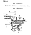
- Fig. 2 is plan view of a main structure of the door outer handle device illustrated in Fig. 1 when the main structure is in a set state;
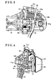
- Fig. 3 is a diagram of the main structure of the door outer handle device when viewed from an inner direction of the door;
- Fig. 4 is a diagram of the main structure of the door outer handle device when viewed from a right side in Fig. 3 (i.e., a rear side of the vehicle);
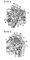
- Fig. 5 is a perspective view of the main structure of the door outer handle device illustrated in Figs. 3 and 4 when viewed from a vehicle rear direction at a door inner side;
- Fig. 6 is a perspective view of the main structure of the door outer handle device illustrated in Figs. 3 and 4 when viewed from a vehicle front direction at the door inner side;
- Fig. 7 is a longitudinal sectional front view illustrating a relationship among a base member, a lever member, and a spring disposed between the base member and the lever member in a state illustrated in Figs. 2 to 6 (i.e., in the set state);
- Fig. 8 is a plan view illustrating a relationship among the base member, the lever member, and an outer handle in the state illustrated in Figs. 2 to 6 (i.e., in the set state);
- Fig. 9 is cross sectional view taken along the line IX-IX in Fig. 8 ;
- Fig. 10 is a perspective view of the base member illustrated in Figs. 2 to 9 when viewed from the vehicle rear direction at the door inner side;
- Fig. 11 is a perspective view of the base member illustrated in Figs. 2 to 9 when viewed from the vehicle front direction at the door inner side;
- Fig. 12 is a front view of the lever member illustrated in Figs. 2 to 9 ;
- Fig. 13 is a plan view of the lever member illustrated in Fig. 12 ;
- Fig. 14 is a longitudinal sectional end view taken along the line XIV-XIV in Fig. 12 ;
- Fig. 15 is a perspective view of the main structure of the door outer handle device when viewed from the vehicle rear direction at the door inner side in a case where the lever member illustrated in Fig. 5 is positioned at a retracted rotation position (i.e., in a retracted state);
- Fig. 16 is a perspective view of the main structure of the door outer handle device when viewed from the vehicle front direction at the door inner side in a case where the lever member illustrated in Fig. 5 is positioned at a retracted rotation position (i.e., in the retracted state);
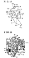
- Fig. 17 is a plan view illustrating a relationship among the base member, the lever member, and the outer handle in a state illustrated in Figs. 15 and 16 (i.e., in the retracted state);
- Fig. 18 is a perspective view of the main structure of the door outer handle device when viewed from the vehicle rear direction at the door inner side in a case where the lever member illustrated in Fig. 5 is in a locked rotation position (i.e., in a locked state; at a time of a vehicle collision where a predetermined inertia force is applied in the vehicle outer direction to the lever member);
- Fig. 19 is a perspective view of the main structure of the door outer handle device when viewed from the vehicle front direction at the door inner side in a case where the lever member illustrated in Fig. 6 is in the locked rotation position;
- Fig. 20 is a diagram of the main structure illustrated in Figs. 18 and 19 when viewed from the door inner side;
- Fig. 21 is a longitudinal sectional front view illustrating a relationship among the base member, the lever member, and the spring disposed between the base member and the lever member in a state illustrated in Figs. 18 to 20 (i.e., in the locked state);
- Fig. 22 is a plan view illustrating a relationship among the base member, the lever member, and the outer handle in a state illustrated in Figs. 18 to 21 (i.e., in the locked state).
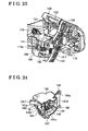
- Fig. 23 is a perspective view of a main structure of a door outer handle device for a vehicle when viewed from a vehicle rear direction at a door inner side according to a second embodiment disclosed here;
- Fig. 24 is a perspective view illustrating a state where a lever member and a coil spring are assembled on a case illustrated in Fig. 23 (i.e., the case, the lever member, the coil spring, and the liker are sub-assembled);
- Fig. 25 is an exploded perspective view of the case, the lever member, and the coil spring illustrated in Fig. 24 ;
- Fig. 26 is a perspective view of the case illustrated in Fig. 25 ;
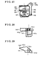
- Fig. 27 is a side view of the case illustrated in Fig. 26 when viewed from a door outer side;
- Fig. 28 is a side view of the lever member illustrated in Fig. 25 when viewed from the door outer side;
- Fig. 29 is a plan view of the lever member illustrated in Fig. 28 ;
- Fig. 30 is an operation explanatory view illustrating the set state of the main structure of the door outer handle device illustrated in Fig. 23 ;
- Fig. 31 is a cross-sectional view illustrating a relationship among the case, the lever member, the coil spring, and the like in the state illustrated in Fig. 30 ;
- Fig. 32 is an operation explanatory view of the main structure in the event of a vehicle collision (i.e., in a state where the lever member is held at the locked rotation position);
- Fig. 33 is an operation explanatory view of the main structure after the vehicle collision (i.e., in a state where a connection lever is returned after the vehicle collision);
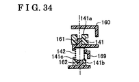
- Fig. 34 is a cross-sectional view illustrating the relationship among the case, the lever member, and the coil spring in the state illustrated in Figs. 32 and 33 .
- FIG. 1 illustrates a door for a vehicle including a door outer handle device for the vehicle according to the first embodiment.
- directions and orientations such as left, right, front, rear, top, and bottom correspond to those of the vehicle at which the door outer handle device is mounted.
- a base member 10 is fixed to a door 100 mounted at a right rear side of the vehicle.
- an outer handle 20, a link mechanism 30, a door opening prevention mechanism 40, and the like are mounted on the base member 10.
- the base member 10 is fixed to an inner side of an outer panel 101 at the door 100 (see Fig. 7 ).
- Figs. 1 illustrates a door for a vehicle including a door outer handle device for the vehicle according to the first embodiment.
- directions and orientations such as left, right, front, rear, top, and bottom correspond to those of the vehicle at which the door outer handle device is mounted.
- a base member 10 is fixed to a door 100 mounted at a right rear side of the vehicle.
- a cap 50 is mounted on a rear end portion 11 of the base member 10 while sandwiching the outer panel 101 (which is omitted in Fig. 2 ) relative to the rear end portion 11 so as to restrain the outer handle 20 from disengaging from the base member 10.
- the outer handle 20 is a grip type handle mounted on the base member 10 and is substantially horizontally arranged so as to be rotatable in inner and outer directions of the vehicle (i.e., a vehicle width direction) (which will be hereinafter referred to as vehicle inner and outer directions).
- the outer handle 20 is assembled on the base member 10 so that the outer panel 101 is sandwiched between the outer handle 20 and the base member 10.
- the outer handle 20 is operable between a door closed position (illustrated by a solid line in Fig. 2 ) and a door open position (illustrated by an imaginary line in Fig. 2 ).
- the door open position is arranged in the vehicle outer direction relative to the door closed position.
- the outer handle 20 includes a front end portion 21 at which the outer handle 20 is rotatably mounted on the base member 10 and includes a rear end portion 22 being movable by a predetermined amount in the vehicle outer direction from a position illustrated by the solid line (i.e., the door closed position) to a position illustrated by the imaginary line (i.e., the door open position) in Fig. 2 .
- An engagement portion 22a (see Fig. 8 ) having substantially an L-shape is formed at the rear end portion 22 of the outer handle 20.
- the engagement portion 22a which serves as a third engagement portion, is engageable with a bell crank 31 serving as a component member of the link mechanism 30 and a lever member 41 serving as a component member of the door opening prevention mechanism 40.
- outer handle 20 In a case where the outer handle 20 is in the door closed position, upper and lower ends of the outer handle 20 are in contact or engagement with the outer panel 101 via respective cushions 102 as illustrated in Fig. 7 . In the case where the outer handle 20 is in the door closed position, the engagement portion 22a may be in contact or engagement with a stopper portion 19 formed at the base member 10 as illustrated in Fig. 8 .
- the link mechanism 30 transmits a door opening operation of the outer handle 20 in the vehicle outer direction as an unlatched operation of a door latch mechanism 60 (i.e., an operation to shift the door latch mechanism 60 from a latched state to an unlatched state).
- the link mechanism 30 includes a coil spring 32 and a connection lever 33 in addition to the bell crank 31.
- the door latch mechanism 60 according to the present embodiment has a known structure including a striker fixed to a vehicle body, a latch and a pawl mounted on the door 100, and the like.
- the pawl restricts a rotation of the latch that engages with the striker to thereby prohibit the door opening operation (i.e., an opening operation of the door 100 that is closed).
- the pawl permits the rotation of the latch that engages with the striker to thereby allow the door opening operation.
- the bell crank 31 includes a shaft portion 31 a, an input arm portion 31b, and an output arm portion 31c.
- the bell crank 31 is rotatably mounted to the base member 10 at the shaft portion 31 a.
- the input arm portion 31 b extends at a radially lower side of the shaft portion 31 a.
- An end of the input arm portion 31 b is in contact or engagement with an outer side surface of the engagement portion 22a of the outer handle 20 as illustrated in Fig. 8 .
- the output arm portion 31c extends at a radially upper side of the shaft portion 31 a.
- the output arm portion 31c is connected to an upper end portion 33a of the connection lever 33 via a connection pin 34.
- connection pin 34 may be integrally formed at the connection lever 33.
- a weight portion (an inertia portion) that extends along the shaft portion 31 a may be provided at the output arm portion 31 c.
- the weight portion at the output arm portion 31 c is provided to restrict the door opening operation of the outer handle 20 that is caused by the inertia force applied to the door 100 in the vehicle outer direction in the event of a vehicle collision.
- restriction force of the weigh portion is specified depending on a mass of the weight portion and a biasing force of the coil spring 32.
- the coil spring 32 is a return spring biasing the bell crank 31 and the outer handle 20 to a set position (i.e., in a set state and the door closed position) illustrated in Figs. 2 to 8 .
- the coil spring 32 is a component member of a return mechanism automatically returning the outer handle 20 from the door open position to the door closed position.
- the coil spring 32 is mounted on an outer periphery of the shaft portion 31 a of the bell crank 31. The coil spring 32 engages with the base member 10 at one end and engages with the bell crank 31 at the other end.
- the coil spring 32 biases the bell crank 31 by a predetermined biasing force in a direction where the input arm portion 31 b engages with the engagement portion 22a of the outer handle 20 (i.e., in a clockwise direction in Fig. 4 ).
- the input arm portion 31 b of the bell crank 31 elastically engages with the engagement portion 22a of the outer handle 20.
- the connection lever 33 includes the upper end portion 33a at which the connection lever 33 is connected to the output arm portion 31 c of the bell crank 31 and includes a lower end portion at which the connection lever 33 is connected to an outside open lever that is connected to the pawl of the door latch mechanism 60.
- the connection lever 33 moves downward by a predetermined amount from a set position (an initial position) as illustrated in Figs. 3 and 4 .
- the connection lever 33 integrally includes a projecting portion 33b having a triangular shape and being engageable with the lever member 41 of the door opening prevention mechanism 40.
- the door latch mechanism 60 In a case where the outer handle 20 is in the door closed position and the connection lever 33 is in the initial position while the door 100 is being closed, the door latch mechanism 60 is in the latched state. In addition, in a case where the outer handle 20 is operated from the door closed position to the door open position and thus the connection lever 33 moves downwardly by the predetermined amount from the initial position, the door latch mechanism 60 is brought to the unlatched state. Therefore, the rotation of the bell crank 31 against the biasing force of the coil spring 32 and the downward movement of the connection lever 33 each correspond to an operation in a door opening direction.
- the door opening prevention mechanism 40 restricts the downward movement of the connection lever 33 of the link mechanism 30 (i.e., the operation in the door opening direction), which is caused by a predetermined inertia force applied to the door 100 in the vehicle outer direction in the event of the vehicle collision while the door 100 is being closed.
- the door opening prevention mechanism 40 includes the lever member 41 assembled on the base member 10 and a coil spring 42 assembled between the lever member 41 and the base member 10.
- Lines A illustrated in Figs. 11 and 12 are reference lines matching each other in a vertical direction in a case where the lever member 41 is arranged in a set rotation position as illustrated in Figs. 2 to 9 .
- the lever member 41 includes an upper shaft portion 41 a, an intermediate shaft portion 41 b, a lower shaft portion 41 c, and a spring attachment shaft portion 41 d.
- the upper shaft portion 41 a, the intermediate shaft portion 41 b, and the lower shaft portion 41 c each serve as a shaft portion.
- the lever member 41 includes an engagement projection 41 e, a stopper projection 41f, a lever portion 41 g, and a shoe portion 41 h.
- the lever member 41 is rotatable from the set rotation position (i.e., an initial rotation position) illustrated in Fig. 8 to a retracted rotation position in the vehicle inner direction as illustrated in Fig. 17 or to a locked rotation position in the vehicle outer direction as illustrated in Fig. 22 .
- the upper shaft portion 41 a is assembled on an upper support portion 12 of the base member 10 so as to be rotatable and movable in an axial direction (i.e., in the vertical direction) by a predetermined amount.
- the intermediate shaft portion 41 b is assembled on an intermediate support portion 13 of the base member 10 so as to be rotatable and movable in the axial direction by a predetermined amount.
- the lower shaft portion 41 c is assembled on a lower support portion 14 of the base member 10 so as to be rotatable and movable in the axial direction by a predetermined amount.
- the spring attachment shaft portion 41 d is formed between the intermediate shaft portion 41 b and the lower shaft portion 41 c.
- a coil portion of the coil spring 42 is assembled on the spring attachment shaft portion 41 d so as to be extendable.
- the engagement projection 41 e is engageable and disengageable relative to the engagement portion 22a of the outer handle 20.
- the engagement projection 41 e is in engagement with the engagement portion 22a of the outer handle 20 until the stopper projection 41f makes contact with a stopper portion 15 of the base member 10 in association with the operation of the outer handle 20 from the door closed position to the door open position.
- the engagement projection 41 e disengages from the engagement portion 22a of the outer handle 20 as illustrated in Fig. 17 .
- the stopper projection 41f is engageable and disengageable relative to the stopper portion 15 of the base member 10.
- the lever portion 41g radially (i.e., substantially horizontally) extends from the upper shaft portion 41 a and the intermediate shaft portion 41 b by a predetermined amount. An end portion of the lever portion 41g extends or retracts relative to a lower side of the projecting portion 33b of the connection lever 33 that is in the initial position. As illustrated in Figs. 8 and 9 , the shoe portion 41 h slidably engages with an upper stepped surface 16 or a lower stepped surface 17 formed at the base member 10.
- the shoe portion 41 h includes an inclination surface 41 h1.
- the shoe portion 41 h (the inclination surface 41h1), an inclination surface (a wall surface) 18 formed between the upper stepped surface 16 and the lower stepped surface 17 of the base member 10, and the coil spring 42 constitute a holding mechanism HM1 for holding the lever member 41 at the locked rotation position.
- the coil spring 42 is a biasing member mounted between the base member 10 and the lever member 41. Specifically, the coil spring 42 engages with the base member 10 at an upper end and engages with the lever member 41 at a lower end. The coil spring 42 biases the lever member 41 to rotate towards the retracted rotation position as illustrated in Fig. 17 and biases the lever member 41 in the axial direction towards a lower position (i.e., a lock holding position) as illustrated in Fig. 21 .
- the inclination surface 18 formed between the upper stepped surface 16 and the lower stepped surface 17 is formed substantially parallel to the inclination surface 41h1 formed at the shoe portion 41h as illustrated in Fig. 9 .
- the inclination surface 18 forms an acute angle with the upper stepped surface 16 and the lower stepped surface 17.
- the inclination surface 41 h1 and the inclination surface 18 are each configured to form an acute angle with the upper stepped surface 16 and the lower stepped surface 17.
- the inclination surface 41h1 and the inclination surface 18 function as wedges when making contact and engaging with each other.
- the inclination surface 41h1 and the inclination surface 18 may form a right angle with the upper stepped surface 16 and the lower stepped surface 17 (i.e., the inclination surface 41h1 and the inclination surface 18 may each form a vertical wall surface relative to the upper stepped surface 16 and the lower stepped surface 17 respectively).
- the lever member 41 is held at the set rotation position as illustrated in Figs. 2 to 9 .
- the engagement portion 22a of the outer handle 20 disengages from the engagement projection 41 e of the lever member 41 in the early stage of the operation of the outer handle 20 from the door closed position to the door open position.
- the lever member 41 rotates in the vehicle inner direction from the set rotation position by the biasing force of the coil spring 42. As a result, the lever member 41 moves to the retracted rotation position as illustrated in Figs. 15 to 17 .
- the lever member 41 rotates in the vehicle outer direction from the set rotation position against the biasing force of the coil spring 42 so as to move to the locked rotation position as illustrated in Figs. 18 to 22 before the outer handle 20 is opened by the predetermined inertia force applied to the door 100 in the vehicle outer direction.
- the lever portion 41 g of the lever member 41 in a case where the lever member 41 is arranged at the set rotation position or the locked rotation position, the lever portion 41 g of the lever member 41 is positioned within a door opening direction movement locus of the connection lever 33 that is the component member of the link mechanism 30 to thereby restrict the connection lever 33 from moving in the door opening direction.
- the lever portion 41 g of the lever member 41 is positioned away from the door opening direction movement locus of the connection lever 33 to thereby allow the connection lever 33 to move in the door opening direction.
- the connection lever 33 is restricted from moving in the opening direction by the lever member 41 in the set rotation position.
- the unlatched operation i.e., the operation to shift the door 100 from the closed state (the latched state) to the open state (the unlatched state) of the door latch mechanism 60 is securely restrained accordingly.
- the lever member 41 rotates in the vehicle inner direction from the set rotation position so as to move to the retracted rotation position in the early stage of the operation from the door closed position to the door open position of the outer handle 20.
- the lever member 41 rotates in the vehicle outer direction from the retracted rotation position so as to move to the set rotation position in the late stage of the operation from the door open position to the door closed position of the outer handle 20.
- the lever member 41 rotates between the set rotation position and the retracted rotation position together with the coil spring 42 in association with a normal operation of the outer handle 20 (i.e., a normal door opening operation).
- a normal operation of the outer handle 20 i.e., a normal door opening operation.
- an attachment and a resulting solidification of dirt or dust at a rotating portion of the lever member 41 may be restrained, which leads to a long term guarantee of the rotation of the lever member 41.
- the rotation of the lever member 41 at a time of a possible vehicle collision may be maintained and guaranteed.
- the door opening prevention mechanism 40 includes the holding mechanism HM1 holding the lever member 41 at the locked rotation position as illustrated in Fig. 9 .
- the lever member 41 moves axially downward (i.e., in a leftward direction in Fig. 9 ) by the biasing force of the coil spring 42 in the axial direction so that the inclination surface 41 h1 of the shoe portion 41 h makes contact and engages with the inclination surface 18 of the base member 10. Accordingly, the lever member 41 is held at the locked rotation position by the holding mechanism HM1.
- the holding mechanism HM1 holds the lever member 41 at the locked rotation position.
- the inertia force applied to the lever member 41 fluctuates and decreases so that the resulting inertia force becomes smaller than the biasing force of the coil spring 42, for example, the lever member 41 is held at the locked rotation position by the holding mechanism HM1.
- the lever member 41 is restrained from returning to the set rotation position from the locked rotation position by the biasing force of the coil spring 42. Regardless of the fluctuation of the inertia force, the function of the door opening prevention mechanism 40 is maintained, which leads to an improved safety of the door outer handle device of the embodiment.
- the lever member 41 includes the engagement projection 41 e serving as a first engagement portion and the stopper projection 41f serving as a second engagement portion.
- the engagement projection 41 e engages with the engagement portion 22a of the outer handle 20 in the door closed position to thereby restrict the rotation of the lever member 41 by the coil spring 42.
- the stopper projection 41f engages with the stopper portion 15 of the base member 10 to thereby restrict the rotation of the lever member 41 by the coil spring 42.
- the outer handle 20 and the lever member 41 are contactable or connectable by a simple structure, i.e., by the engagement portion 22a of the outer handle 20 and the engagement projection 41e of the lever member 41.
- the rotation of the lever member 41 relative to the base member 10 is restricted by a simple structure, i.e., by the stopper portion 15 of the base member 10 and the stopper projection 41f of the lever member 41.
- the door outer handle device at a low cost is achievable.
- the rotation of the lever member 41 relative to the base member 10 is regulated to a minimum level, which leads to a space reduction in the door outer handle device.
- the lever member 41 of the door opening prevention mechanism 40 is directly assembled on the base member 10 so that the lever member 41 is rotatable relative to the base member 10 by a predetermined amount.
- a lever member 141 of a door opening prevention mechanism 140 is assembled on a base member 110 via a case 160 so that the lever member 141 is rotatable relative to the base member 110 by a predetermined amount.
- a door outer handle device for a vehicle includes a holding mechanism HM2 (see Figs. 24 and 32 ) similar to the holding mechanism HM1 of the first embodiment.
- the second embodiment also includes a lock release mechanism KM (see Fig. 33 ).
- the second embodiment includes a link mechanism 130 similar to the link mechanism 30 of the first embodiment.
- Configurations of the link mechanism 130 such as a bell crank 131, a coil spring 132, a connection lever 133 and a connection pin 134, except for a shape of the connection lever 133, are substantially the same as those of the link mechanism 30 of the first embodiment such as the bell crank 31, the coil spring 32, the connection lever 33, and the connection pin 34.
- the case 160 covers and protects a large portion of the lever member 141 (i.e., fails to cover or protect only a portion thereof) and substantially an entire portion of a coil spring 142.
- the case 160 includes an upper support portion 161 (shaft portion) and a lower support portion 162 (shaft portion) corresponding to the upper support portion 12, the intermediate support portion 13, and the lower support portion 14 of the first embodiment, and an upper stepped surface 163 and a lower stepped surface 164 corresponding to the upper stepped surface 16 and the lower stepped surface 17 of the first embodiment.
- the case 160 includes an attachment piece 165 having an attachment bore 165a, a positioning pin 166 fitted to a pin bore 110a formed at the base member 110 in a case where the case 160 is assembled on the base member 110, and a detent projection 167 inhibiting the case 160 from rotating when the case 160 is assembled on the base member 110 by a screw 170.
- the detent projection 167 is configured to engage with a portion of the base member 110.
- the lever member 141 includes an upper shaft portion (hollow shaft portion) 141 a, a lower shaft portion (hollow shaft portion) 141 b, and a spring holding portion 141c.
- the lever member 141 also includes an engagement projection 141d, a stopper engagement portion 141e, a lever portion 141f, and a shoe portion 141g.
- the lever member 141 is rotatable from the set rotation position (i.e., the initial rotation position) illustrated in Figs. 23 and 30 to the retracted rotation position in the vehicle inner direction or to the locked rotation position in the vehicle outer direction as illustrated in Figs. 32 to 34 .
- the upper shaft portion 141 a is assembled on the upper support portion 161 of the case 160 so as to be rotatable and axially movable (i.e., movable in the vertical direction) by a predetermined amount relative to the upper support portion 161.
- the lower shaft portion 141 b is assembled on the lower support portion 162 of the case 160 so as to be rotatable and axially movable (i.e., movable in the vertical direction) by a predetermined amount relative to the lower support portion 162.
- the spring holding portion 141 c is provided between the upper shaft portion 141 a and the lower shaft portion 141 b so that a lower end portion of the coil spring 142 expands and contracts.
- the engagement projection 141d is engageable and disengageable relative to an engagement portion 122a of an outer handle 120.
- the engagement projection 141d is in engagement with the engagement portion 122a of the outer handle 120 until the stopper engagement portion 141e makes contact with a stopper portion 168 of the case 160 in association with the operation of the outer handle 120 from the door closed position to the door open position.
- the engagement projection 141d disengages from the engagement portion 122a of the outer handle 120.
- the stopper engagement portion 141e is engageable and disengageable relative to the stopper portion 168 of the case 160.
- the lever portion 141f radially (i.e., substantially horizontally) extends from the upper shaft portion 141a by a predetermined amount. An end portion of the lever portion 141f extends or retracts relative to a lower side of a projecting portion 133b of the connection lever 133 that is in the initial position. As illustrated in Figs. 30 and 32 , the shoe portion 141g slidably engages with the upper stepped surface 163 or the lower stepped surface 164 formed at the case 160.
- the shoe portion 141g includes a vertical wall.
- the shoe portion 141g (the vertical wall), a vertical wall surface W formed between the upper stepped surface 163 and the lower stepped surface 164 of the case 160, and the coil spring 142 constitute a holding mechanism HM2 for holding the lever member 141 at the locked rotation position.
- the coil spring 142 is a biasing member mounted between the case 160 and the lever member 141. Specifically, the coil spring 142 engages with the case 160 at an upper end and engages with the lever member 141 at a lower end. The coil spring 142 biases the lever member 141 to rotate towards the retracted rotation position and biases the lever member 141 in the axial direction towards a lower position (i.e., the lock holding position) as illustrated in Figs. 32 to 34 . A coil portion of the coil spring 142 is held by the spring holding portion 141 c formed at the lever member 141 and also by a spring holding portion 169 formed at the case 160.
- the lock release mechanism KM releases the lever member 141, which is held at the locked rotation position by the holding mechanism HM2 in association with a return operation by the coil spring 132 (return mechanism) of the link mechanism 130, from the locked rotation position. Specifically, the lock release mechanism KM upwardly presses the lever member 141 against the biasing force of the coil spring 142 in the axial direction.
- the lock release mechanism KM is constituted by a release portion 133c formed at the lever member 141.
- the lever member 141 that is released from the locked rotation position by the lock release mechanism KM is configured to return to the set rotation position by the biasing force of the coil spring 142 (biasing member).
- the second embodiment is configured in the substantially same manner as the first embodiment except that the door opening prevention mechanism 140 includes the lock release mechanism KM, and the lever member 141 of the door opening prevention mechanism 140 is assembled on the base member 110 via the case 160. Accordingly, the second embodiment obtains substantially the same effects as those of the first embodiment.
- the case 160 is provided so as to cover and protect the large portion of the lever member 141 and substantially the entire portion of the coil spring 142.
- the lever member 141, the coil spring 142, and the like are unlikely to be adversely affected by dust, dirt, water, and the like.
- a rotation failure of the lever member 141 is restrained, thereby improving reliability of the door outer handle device.
- the lock release mechanism KM (the release portion 133c) is provided so as to release the lever member 141, which is held at the locked rotation position by the holding mechanism HM2 in association with the return operation by the coil spring 132 of the link mechanism 130, from the locked rotation position.
- the lever member 141 that is released from the locked rotation position by the lock release mechanism KM is configured to return to the set rotation position by the biasing force of the coil spring 142. Therefore, after the vehicle collision (i.e., the inertia force disappears), the lever member 141 is released from the locked rotation position so as to return to the set rotation position by a cooperation of the coil spring 132, the lock release mechanism KM, the coil spring 142, and the like. Therefore, after the vehicle collision, the outer handle 120 is operated from the door closed position to the door open position to thereby open the door 100.
- the lever member 41, 141 of the door opening prevention mechanism 40, 140 is extendable and retractable relative to the connection lever 33, 133 of the link mechanism 30, 130, i.e., the lever member 41, 141 is positioned within the door opening direction movement locus of the projecting portion 33b, 133b of the connection lever 33, 133 or is positioned out of the door opening direction movement locus of the projecting portion 33b, 133b.
- the lever member 41, 141 of the door opening prevention mechanism 40, 140 may be extendable and retractable relative to the other component member, such as a rod and a bell crank, than the connection lever 33, 133 of the link mechanism 30, 130.
- the projecting portion 33b, 133b of the connection lever 33, 133 may be provided as a separate member.
- the holding mechanism HM1, HM2 is provided to hold the lever member 41, 141 at the locked rotation position.
- the holding mechanism HM1, HM2 may be omitted to achieve the door outer handle device of the embodiments.
- the stopper projection 41f is formed at the lever member 41 while the stopper portion 15 is formed at the base member 10.
- the stopper projection 41f and the stopper portion 15 may not be provided to achieve the door outer handle device of the first embodiment.
- a weight portion (an inertia portion) may be provided at the bell crank 31, 131.
- the lever member 41, 141 of the door opening prevention mechanism 40, 140 is rotatable from the set rotation position in the vehicle inner direction to the retracted rotation position or in the vehicle outer direction to the locked rotation position.
- the lever member 41 , 141 rotates from the set rotation position in the vehicle outer direction to the locked rotation position against the biasing force of the coil spring 42, 142 (the biasing member) by the predetermined inertia force (i.e., the inertia force is applied to the lever member 41, 141).
- the lever member 41, 141 of the door opening prevention mechanism 40, 140 may be rotatable from the set rotation position in the vehicle inner direction to the retracted rotation position.
- the lever member 41, 141 may be retained at the set rotation position against the biasing force of the coil spring 42, 142 by the predetermined inertia force (i.e., the locked rotation position in the vehicle outer direction may not be specified and thus the lever member 41, 141 is configured not to move to the locked rotation position by the predetermined inertial force in the event of the vehicle collision).
- the lever member 41, 141 of the door opening prevention mechanism 40, 140 and the component member of the link mechanism 30, 130 such as the connection lever 33, 133 are separately formed.
- the lever member 41, 141 and the component member of the link mechanism 30, 130 may be integrally formed. Then, the resulting integral member may move to the set rotation position, the retracted rotation position, and the locked rotation position.
- the door outer handle device is provided to the door 100 at a right rear side of the vehicle.
- the door outer handle device of the embodiment may be provided to the door 100 at a left rear side, a right front side, or a left front side of the vehicle in the same way or in an appropriately modified manner.
- the door outer handle device may be applicable to a door at a rear side of the vehicle (i.e., a back door) in the same way or in an appropriately modified manner.
- a door outer handle device for a vehicle includes a base member (10, 110), an outer handle (20, 120), a link mechanism (30, 130), and a door opening prevention mechanism (40, 140) restricting a component member (33, 133) of the link mechanism from moving in a door opening direction by a predetermined inertia force.
- the door opening prevention mechanism (40, 140) includes a lever member (41, 141) being rotatable to a set rotation position to restrict the component member from moving in the door opening direction.
- the lever member (41, 141) is rotatable to a retracted rotation position to allow the component member to move in the door opening direction by being shifted to the retracted rotation position in an early stage of an operation of the outer handle (20, 120) from the door closed position to the door open position while the inertia force is not being applied.
- the door opening prevention mechanism (40, 140) further includes a biasing member (42, 142) biasing the lever member to the retracted rotation position.
Landscapes
- Lock And Its Accessories (AREA)
Abstract
Description
- This disclosure generally relates to a door outer handle device for a vehicle.
- A known door outer handle device for a vehicle includes a base member fixed to a door for the vehicle, an outer handle, a link mechanism, and a door opening prevention mechanism. The outer handle is attached to the base member in a movable manner in inward and outward directions of the vehicle (i.e., vehicle inward and outward directions) so as to be operable between a door closed position and a door open position. The link mechanism transmits a door opening operation of the outer handle as an unlatched operation of a door latch mechanism. The door opening prevention mechanism restricts an operation of a component member of the link mechanism in a door opening direction by a predetermined inertia force applied to the door in the vehicle outer direction in a case of a vehicle collision (i.e., the door opening prevention mechanism invalidates a function of the link mechanism).
- In the event of the vehicle collision, the component member of the link mechanism operates in the door opening direction because the outer handle is opened by the predetermined inertia force applied to the door in the vehicle outward direction at a time of the vehicle collision. The unlatched operation of the door latch mechanism is an operation to bring the door latch mechanism in a latched state to an unlatched state. In the latched state of the door latch mechanism, it is impossible to open the door of the vehicle when in a closed state. In the unlatched state of the door latch mechanism, it is possible to open the door of the vehicle when in the closed state.
- The aforementioned door outer handle device is disclosed in
JP2009-243101A - According to the door outer handle device disclosed in Reference 1, in a case where the inertia stopper member is maintained at the set rotation position by the biasing force of the biasing member, the inertia stopper member is positioned out of the door opening direction movement locus, thereby allowing the link mechanism to operate in the door opening direction. The door for the vehicle is thus opened by the door opening operation of the outer handle.
- In the door outer handle device disclosed in Reference 1, before the outer handle is opened by the predetermined inertia force applied in the door outward direction in the event of the vehicle collision, the predetermined inertia force is applied to the inertia stopper member. Then, the inertia stopper member rotates from the set rotation position to the locked rotation position in the vehicle outward direction against the biasing force of the biasing member. As a result, the portion of the inertia stopper member moves within the door opening direction movement locus of the component member from an outside thereof.
- Therefore, as long as the inertia stopper member appropriately or normally rotates in the event of the vehicle collision, a certain operation is obtained by the door opening prevention mechanism. However, in a case where the inertia stopper member does not appropriately rotate and thus an operation responsiveness of the inertia stopper member in the door outer direction by the inertia force is insufficient, the component member of the link mechanism may not be restricted from operating in the door opening direction by the inertia stopper member. Consequently, the unlatched operation of the door latch mechanism may not be securely prevented.
- In addition, according to the door outer handle device disclosed in Reference 1, the inertia stopper member is normally held at the set rotation position (i.e., the initial position) by the biasing force of the biasing member. The inertia stopper member is configured so as not to rotate by a normal operation of the outer handle (i.e., a normal door opening operation). Thus, dirt or dust may be attached and solidified at a rotation portion of the inertia stopper member. As a result, a rotation of the inertia stopper member may not be guaranteed for a long period of time, which may prevent a predetermined rotation of the inertia stopper member at a time of a possible vehicle collision.
- A need thus exists for a door outer handle device for a vehicle which securely restrains an unlatch operation of a door latch mechanism and obtains a predetermined rotation of an inertia stopper member (a lever member) in the event of a vehicle collision.
- According to an aspect of this disclosure, a door outer handle device for a vehicle includes a base member configured to be fixed to a door for the vehicle, an outer handle attached to the base member in a movable manner in vehicle inner and outer directions, the outer handle being operable between a door closed position and a door open position, the door open position being arranged in the vehicle outer direction relative to the door closed position, a link mechanism configured to transmit a door opening operation of the outer handle as an unlatched operation of a door latch mechanism, and a door opening prevention mechanism restricting a component member of the link mechanism from moving in a door opening direction by a predetermined inertia force applied to the door in the vehicle outer direction. The door opening prevention mechanism includes a lever member being rotatable to a set rotation position where the lever member is held at the base member to restrict the component member of the link mechanism from moving in the door opening direction in a case where the outer handle is arranged at the door closed position. The lever member is rotatable to a retracted rotation position that is positioned at least in the vehicle inner direction from the set rotation position. The lever member is shifted to the retracted rotation position in an early stage of an operation of the outer handle from the door closed position to the door open position in a case where the outer handle is operated from the door closed position to the door open position in a state where the inertia force is prevented from being applied. The lever member allows the component member of the link mechanism to move in the door opening direction when the lever member is arranged at the retracted rotation position. The door opening prevention mechanism further includes a biasing member biasing the lever member to the retracted rotation position.
- Accordingly, in a case where the lever member is arranged at the set rotation position, the lever member restricts the component member of the link mechanism from moving in the door opening direction. Thus, in the event of the vehicle collision, the lever member at the set rotation position restricts the component member from moving in the door opening direction to thereby securely prevent the unlatched operation of the door latch mechanism (i.e., an operation to shift the door from the door closed state (latched state) to the door open state (the unlatched state)).
- In addition, in a case where the outer handle is operated from the door closed position to the door open position in a state where the inertia force is not applied, the lever member rotates from the set rotation position in the vehicle inner direction to the retracted rotation position in the early stage of the operation from the door closed position to the door open position of the outer handle (on the other hand, in a case where the outer handle is returned from the door open position to the door closed position in a state where the inertia force is not applied, the lever member rotates from the retracted rotation position in the vehicle outer direction to move to the set rotation position in the later stage of the operation from the door open position to the door closed position of the outer handle.) Thus, the lever member operates together with the biasing member in association with a normal operation (i.e., a normal door opening operation) of the outer handle so as to rotate between the set rotation position and the retracted rotation position. Consequently, an attachment and solidification of dirt or dust at a rotation portion of the lever member may be restrained, which leads to a long term guarantee of the rotation of the lever member.
- The lever member is maintained at the set rotation position against a biasing force of the biasing member in a state where the inertia force is applied.
- Accordingly, in the event of the vehicle collision, the lever member at the set rotation position restricts the component member of the link mechanism from moving in the door opening direction to thereby securely prevent the unlatched operation of the door latch mechanism.
- According to another aspect of this disclosure, a door outer handle device for a vehicle includes a base member configured to be fixed to a door for the vehicle, an outer handle attached to the base member in a movable manner in vehicle inner and outer directions, the outer handle being operable between a door closed position and a door open position, the door open position being arranged in the vehicle outer direction relative to the door closed position, a link mechanism configured to transmit a door opening operation of the outer handle as an unlatched operation of a door latch mechanism, and a door opening prevention mechanism restricting a component member of the link mechanism from moving in a door opening direction by a predetermined inertia force applied to the door in the vehicle outer direction. The door opening prevention mechanism includes a lever member being rotatable to a set rotation position where the lever member is held at the base member to restrict the component member of the link mechanism from moving in the door opening direction in a case where the outer handle is arranged at the door closed position in a state where the inertia force is prevented from being applied The lever member is rotatable to a retracted rotation position that is positioned at least in the vehicle inner direction from the set rotation position. The lever member is shifted to the retracted rotation position in an early stage of an operation of the outer handle from the door closed position to the door open position in a case where the outer handle is operated from the door closed position to the door open position in a state where the inertia force is prevented from being applied. The lever member allows the component member of the link mechanism to move in the door opening direction when the lever member is arranged at the retracted rotation position. The lever member is rotatable to a locked rotation position that is positioned at least in the vehicle outer direction from the set rotation position. The lever member is shifted to the locked rotation position to restrict the component member of the link mechanism from moving in the door opening direction in a state where the inertia force is applied. The door opening prevention mechanism further includes a biasing member biasing the lever member to the retracted rotation position.
- Accordingly, in a case where the lever member is arranged at the set rotation position or the locked rotation position, the lever member restricts the component member of the link mechanism from moving in the door opening direction. Thus, in the event of the vehicle collision, the lever member in the set rotation position or the locked rotation position restricts the component member from moving in the door opening direction to thereby securely prevent the unlatched operation of the door latch mechanism.
- In addition, in a case where the outer handle is operated from the door closed position to the door open position in a state where the inertia force is not applied, the lever member rotates from the set rotation position in the vehicle inner direction to the retracted rotation position in the early stage of the operation from the door closed position to the door open position of the outer handle (on the other hand, in a case where the outer handle is returned from the door open position to the door closed position in a state where the inertia force is not applied, the lever member rotates from the retracted rotation position in the vehicle outer direction to move to the set rotation position in the later stage of the operation from the door open position to the door closed position of the outer handle.) Thus, the lever member operates together with the biasing member in association with a normal operation (i.e., a normal door opening operation) of the outer handle so as to rotate between the set rotation position and the retracted rotation position. Consequently, an attachment and solidification of dirt or dust at a rotation portion of the lever member may be restrained, which leads to a long term guarantee of the rotation of the lever member.
- The lever member is shifted to the locked rotation position against a biasing force of the biasing member in a state where the inertia force is applied.
- Accordingly, in the event of the vehicle collision, the lever member at the locked rotation position restricts the component member from moving in the door opening direction to thereby securely prevent the unlatched operation of the door latch mechanism.
- The lever member includes a first engagement portion and a second engagement portion, the first engagement portion engaging with a portion of the outer handle in the door closed position and restricting the lever member from rotating by the biasing member in a case where the lever member is arranged at the set rotation position, the second engagement portion engaging with the base member and restricting the lever member from rotating by the biasing member in a case where the lever member is arranged at the retracted rotation position.
- Accordingly, the outer handle and the lever member are contactable or connectable by a simple structure, i.e., by the portion of the outer handle and the first engagement portion of the lever member. In addition, the rotation of the lever member relative to the base member is restricted by a simple structure, i.e., by the base member and the second engagement portion of the lever member. As a result, a low cost is achievable according to the door outer handle device of this disclosure. Further, the rotation of the lever member relative to the base member is regulated to a minimum level, which leads to a space reduction in the door outer handle device of the disclosure.
- The outer handle includes a third engagement portion engaging with the link mechanism and selectively engaging with the first engagement portion.
- Accordingly, the outer handle and the lever member are contactable or connectable by a simple structure, i.e., by the third engagement portion of the outer handle and the first engagement portion of the lever member. As a result, a low cost is achievable according to the door outer handle device of this disclosure.
- The base member includes a stopper portion selectively engaging with the second engagement portion.
- Accordingly, the rotation of the lever member relative to the base member is restricted by a simple structure, i.e., by the stopper portion of the base member and the second engagement portion of the lever member. As a result, a low cost is achievable according to the door outer handle device of this disclosure. Further, the rotation of the lever member relative to the base member is regulated to a minimum level, which leads to a space reduction in the door outer handle device of the disclosure.
- The door opening prevention mechanism includes a holding mechanism to hold the lever member at the locked rotation position.
- Accordingly, in a case where the lever member moves from the set rotation position to the locked rotation position by the predetermined inertia force applied to the lever member in the event of the vehicle collision, the holding mechanism holds the lever member at the locked rotation position. Thus, even thereafter the inertia force applied to the lever member fluctuates and decreases so that the resulting inertia force becomes smaller than the biasing force of the biasing member, for example, the lever member is held at the locked rotation position by the holding mechanism and is restrained from returning to the set rotation position from the locked rotation position by the biasing force of the biasing member. Regardless of the fluctuation of the inertia force, the function of the door opening prevention mechanism is maintained, which leads to an improved safety of the door outer handle device.
- The holding mechanism includes a shoe portion engaging with the base member in a direction from the locked rotation position to the set rotation position of the lever member, wherein the lever member includes a shaft portion assembled on the base member to be rotatable and movable in an axial direction of the lever member, and wherein the biasing member biases the lever member in the axial direction so that the shoe portion engages with the base member.
- Accordingly, in a case where the lever member moves from the set rotation position to the locked rotation position by the predetermined inertia force applied to the lever member in the event of the vehicle collision, the holding mechanism holds the lever member at the locked rotation position. Thus, even thereafter the inertia force applied to the lever member fluctuates and decreases so that the resulting inertia force becomes smaller than the biasing force of the biasing member, for example, the lever member is held at the locked rotation position by the holding mechanism and is restrained from returning to the set rotation position from the locked rotation position by the biasing force of the biasing member. Regardless of the fluctuation of the inertia force, the function of the door opening prevention mechanism is maintained, which leads to an improved safety of the door outer handle device.
- The link mechanism includes a return mechanism automatically returning the outer handle from the door open position to the door closed position and a lock release mechanism releasing the lever member, which is held at the locked rotation position by the holding mechanism in association with a return operation by the return mechanism, from the locked rotation position.
- Accordingly, the lever member that is released from the locked rotation position by the lock release mechanism is configured to return to the set rotation position by the biasing force of the biasing member. Therefore, after the vehicle collision (i.e., the inertia force disappears), the lever member is released from the locked rotation position so as to return to the set rotation position by a cooperation of the return mechanism, the lock release mechanism, the biasing member, and the like. Therefore, after the vehicle collision, the outer handle is operated from the door closed position to the door open position to thereby open the door.
- The foregoing and additional features and characteristics of this disclosure will become more apparent from the following detailed description considered with the reference to the accompanying drawings, wherein:
-
Fig. 1 is a partial perspective view of a door for a vehicle including a door outer handle device for the vehicle when viewed from an outer side of the vehicle according to a first embodiment disclosed here; -
Fig. 2 is plan view of a main structure of the door outer handle device illustrated inFig. 1 when the main structure is in a set state; -
Fig. 3 is a diagram of the main structure of the door outer handle device when viewed from an inner direction of the door; -
Fig. 4 is a diagram of the main structure of the door outer handle device when viewed from a right side inFig. 3 (i.e., a rear side of the vehicle); -
Fig. 5 is a perspective view of the main structure of the door outer handle device illustrated inFigs. 3 and 4 when viewed from a vehicle rear direction at a door inner side; -
Fig. 6 is a perspective view of the main structure of the door outer handle device illustrated inFigs. 3 and 4 when viewed from a vehicle front direction at the door inner side; -
Fig. 7 is a longitudinal sectional front view illustrating a relationship among a base member, a lever member, and a spring disposed between the base member and the lever member in a state illustrated inFigs. 2 to 6 (i.e., in the set state); -
Fig. 8 is a plan view illustrating a relationship among the base member, the lever member, and an outer handle in the state illustrated inFigs. 2 to 6 (i.e., in the set state); -
Fig. 9 is cross sectional view taken along the line IX-IX inFig. 8 ; -
Fig. 10 is a perspective view of the base member illustrated inFigs. 2 to 9 when viewed from the vehicle rear direction at the door inner side; -
Fig. 11 is a perspective view of the base member illustrated inFigs. 2 to 9 when viewed from the vehicle front direction at the door inner side; -
Fig. 12 is a front view of the lever member illustrated inFigs. 2 to 9 ; -
Fig. 13 is a plan view of the lever member illustrated inFig. 12 ; -
Fig. 14 is a longitudinal sectional end view taken along the line XIV-XIV inFig. 12 ; -
Fig. 15 is a perspective view of the main structure of the door outer handle device when viewed from the vehicle rear direction at the door inner side in a case where the lever member illustrated inFig. 5 is positioned at a retracted rotation position (i.e., in a retracted state); -
Fig. 16 is a perspective view of the main structure of the door outer handle device when viewed from the vehicle front direction at the door inner side in a case where the lever member illustrated inFig. 5 is positioned at a retracted rotation position (i.e., in the retracted state); -
Fig. 17 is a plan view illustrating a relationship among the base member, the lever member, and the outer handle in a state illustrated inFigs. 15 and 16 (i.e., in the retracted state); -
Fig. 18 is a perspective view of the main structure of the door outer handle device when viewed from the vehicle rear direction at the door inner side in a case where the lever member illustrated inFig. 5 is in a locked rotation position (i.e., in a locked state; at a time of a vehicle collision where a predetermined inertia force is applied in the vehicle outer direction to the lever member); -
Fig. 19 is a perspective view of the main structure of the door outer handle device when viewed from the vehicle front direction at the door inner side in a case where the lever member illustrated inFig. 6 is in the locked rotation position; -
Fig. 20 is a diagram of the main structure illustrated inFigs. 18 and19 when viewed from the door inner side; -
Fig. 21 is a longitudinal sectional front view illustrating a relationship among the base member, the lever member, and the spring disposed between the base member and the lever member in a state illustrated inFigs. 18 to 20 (i.e., in the locked state); and -
Fig. 22 is a plan view illustrating a relationship among the base member, the lever member, and the outer handle in a state illustrated inFigs. 18 to 21 (i.e., in the locked state). -
Fig. 23 is a perspective view of a main structure of a door outer handle device for a vehicle when viewed from a vehicle rear direction at a door inner side according to a second embodiment disclosed here; -
Fig. 24 is a perspective view illustrating a state where a lever member and a coil spring are assembled on a case illustrated inFig. 23 (i.e., the case, the lever member, the coil spring, and the liker are sub-assembled); -
Fig. 25 is an exploded perspective view of the case, the lever member, and the coil spring illustrated inFig. 24 ; -
Fig. 26 is a perspective view of the case illustrated inFig. 25 ; -
Fig. 27 is a side view of the case illustrated inFig. 26 when viewed from a door outer side; -
Fig. 28 is a side view of the lever member illustrated inFig. 25 when viewed from the door outer side; -
Fig. 29 is a plan view of the lever member illustrated inFig. 28 ; -
Fig. 30 is an operation explanatory view illustrating the set state of the main structure of the door outer handle device illustrated inFig. 23 ; -
Fig. 31 is a cross-sectional view illustrating a relationship among the case, the lever member, the coil spring, and the like in the state illustrated inFig. 30 ; -
Fig. 32 is an operation explanatory view of the main structure in the event of a vehicle collision (i.e., in a state where the lever member is held at the locked rotation position); -
Fig. 33 is an operation explanatory view of the main structure after the vehicle collision (i.e., in a state where a connection lever is returned after the vehicle collision); and -
Fig. 34 is a cross-sectional view illustrating the relationship among the case, the lever member, and the coil spring in the state illustrated inFigs. 32 and 33 . - A first embodiment will be explained with reference to
Figs. 1 to 22 .Fig. 1 illustrates a door for a vehicle including a door outer handle device for the vehicle according to the first embodiment. In the embodiment, directions and orientations such as left, right, front, rear, top, and bottom correspond to those of the vehicle at which the door outer handle device is mounted. InFig. 1 , abase member 10 is fixed to adoor 100 mounted at a right rear side of the vehicle. As illustrated inFig. 2 , anouter handle 20, alink mechanism 30, a dooropening prevention mechanism 40, and the like are mounted on thebase member 10. Thebase member 10 is fixed to an inner side of anouter panel 101 at the door 100 (seeFig. 7 ). As illustrated inFigs. 1 and2 , acap 50 is mounted on arear end portion 11 of thebase member 10 while sandwiching the outer panel 101 (which is omitted inFig. 2 ) relative to therear end portion 11 so as to restrain theouter handle 20 from disengaging from thebase member 10. - The
outer handle 20 is a grip type handle mounted on thebase member 10 and is substantially horizontally arranged so as to be rotatable in inner and outer directions of the vehicle (i.e., a vehicle width direction) (which will be hereinafter referred to as vehicle inner and outer directions). Theouter handle 20 is assembled on thebase member 10 so that theouter panel 101 is sandwiched between theouter handle 20 and thebase member 10. Theouter handle 20 is operable between a door closed position (illustrated by a solid line inFig. 2 ) and a door open position (illustrated by an imaginary line inFig. 2 ). The door open position is arranged in the vehicle outer direction relative to the door closed position. Theouter handle 20 includes afront end portion 21 at which theouter handle 20 is rotatably mounted on thebase member 10 and includes arear end portion 22 being movable by a predetermined amount in the vehicle outer direction from a position illustrated by the solid line (i.e., the door closed position) to a position illustrated by the imaginary line (i.e., the door open position) inFig. 2 . Anengagement portion 22a (seeFig. 8 ) having substantially an L-shape is formed at therear end portion 22 of theouter handle 20. Theengagement portion 22a, which serves as a third engagement portion, is engageable with a bell crank 31 serving as a component member of thelink mechanism 30 and alever member 41 serving as a component member of the dooropening prevention mechanism 40. In a case where theouter handle 20 is in the door closed position, upper and lower ends of theouter handle 20 are in contact or engagement with theouter panel 101 viarespective cushions 102 as illustrated inFig. 7 . In the case where theouter handle 20 is in the door closed position, theengagement portion 22a may be in contact or engagement with astopper portion 19 formed at thebase member 10 as illustrated inFig. 8 . - The
link mechanism 30 transmits a door opening operation of theouter handle 20 in the vehicle outer direction as an unlatched operation of a door latch mechanism 60 (i.e., an operation to shift thedoor latch mechanism 60 from a latched state to an unlatched state). As illustrated inFigs. 2 to 6 , thelink mechanism 30 includes acoil spring 32 and aconnection lever 33 in addition to thebell crank 31. Thedoor latch mechanism 60 according to the present embodiment has a known structure including a striker fixed to a vehicle body, a latch and a pawl mounted on thedoor 100, and the like. In the latched state of thedoor latch mechanism 60, the pawl restricts a rotation of the latch that engages with the striker to thereby prohibit the door opening operation (i.e., an opening operation of thedoor 100 that is closed). In the unlatched state of thedoor latch mechanism 60, the pawl permits the rotation of the latch that engages with the striker to thereby allow the door opening operation. - As illustrated in
Fig. 3 , the bell crank 31 includes ashaft portion 31 a, aninput arm portion 31b, and anoutput arm portion 31c. Thebell crank 31 is rotatably mounted to thebase member 10 at theshaft portion 31 a. Theinput arm portion 31 b extends at a radially lower side of theshaft portion 31 a. An end of theinput arm portion 31 b is in contact or engagement with an outer side surface of theengagement portion 22a of theouter handle 20 as illustrated inFig. 8 . Theoutput arm portion 31c extends at a radially upper side of theshaft portion 31 a. Theoutput arm portion 31c is connected to anupper end portion 33a of theconnection lever 33 via aconnection pin 34. At this time, theconnection pin 34 may be integrally formed at theconnection lever 33. In addition, a weight portion (an inertia portion) that extends along theshaft portion 31 a may be provided at theoutput arm portion 31 c. The weight portion at theoutput arm portion 31 c is provided to restrict the door opening operation of theouter handle 20 that is caused by the inertia force applied to thedoor 100 in the vehicle outer direction in the event of a vehicle collision. Such restriction force of the weigh portion is specified depending on a mass of the weight portion and a biasing force of thecoil spring 32. - The
coil spring 32 is a return spring biasing the bell crank 31 and theouter handle 20 to a set position (i.e., in a set state and the door closed position) illustrated inFigs. 2 to 8 . Thecoil spring 32 is a component member of a return mechanism automatically returning theouter handle 20 from the door open position to the door closed position. Thecoil spring 32 is mounted on an outer periphery of theshaft portion 31 a of thebell crank 31. Thecoil spring 32 engages with thebase member 10 at one end and engages with the bell crank 31 at the other end. Thecoil spring 32 biases the bell crank 31 by a predetermined biasing force in a direction where theinput arm portion 31 b engages with theengagement portion 22a of the outer handle 20 (i.e., in a clockwise direction inFig. 4 ). Thus, theinput arm portion 31 b of the bell crank 31 elastically engages with theengagement portion 22a of theouter handle 20. - The
connection lever 33 includes theupper end portion 33a at which theconnection lever 33 is connected to theoutput arm portion 31 c of the bell crank 31 and includes a lower end portion at which theconnection lever 33 is connected to an outside open lever that is connected to the pawl of thedoor latch mechanism 60. In a case where the bell crank 31 rotates by a predetermined amount against the biasing force of thecoil spring 32 at a time when theouter handle 20 is operated from the door closed position to the door open position, theconnection lever 33 moves downward by a predetermined amount from a set position (an initial position) as illustrated inFigs. 3 and 4 . Theconnection lever 33 integrally includes a projectingportion 33b having a triangular shape and being engageable with thelever member 41 of the dooropening prevention mechanism 40. - In a case where the
outer handle 20 is in the door closed position and theconnection lever 33 is in the initial position while thedoor 100 is being closed, thedoor latch mechanism 60 is in the latched state. In addition, in a case where theouter handle 20 is operated from the door closed position to the door open position and thus theconnection lever 33 moves downwardly by the predetermined amount from the initial position, thedoor latch mechanism 60 is brought to the unlatched state. Therefore, the rotation of the bell crank 31 against the biasing force of thecoil spring 32 and the downward movement of theconnection lever 33 each correspond to an operation in a door opening direction. - The door
opening prevention mechanism 40 restricts the downward movement of theconnection lever 33 of the link mechanism 30 (i.e., the operation in the door opening direction), which is caused by a predetermined inertia force applied to thedoor 100 in the vehicle outer direction in the event of the vehicle collision while thedoor 100 is being closed. The dooropening prevention mechanism 40 includes thelever member 41 assembled on thebase member 10 and acoil spring 42 assembled between thelever member 41 and thebase member 10. Lines A illustrated inFigs. 11 and12 are reference lines matching each other in a vertical direction in a case where thelever member 41 is arranged in a set rotation position as illustrated inFigs. 2 to 9 . - As illustrated in
Figs. 12 to 14 , thelever member 41 includes anupper shaft portion 41 a, anintermediate shaft portion 41 b, alower shaft portion 41 c, and a springattachment shaft portion 41 d. Theupper shaft portion 41 a, theintermediate shaft portion 41 b, and thelower shaft portion 41 c each serve as a shaft portion. In addition, thelever member 41 includes anengagement projection 41 e, astopper projection 41f, alever portion 41 g, and ashoe portion 41 h. Thelever member 41 is rotatable from the set rotation position (i.e., an initial rotation position) illustrated inFig. 8 to a retracted rotation position in the vehicle inner direction as illustrated inFig. 17 or to a locked rotation position in the vehicle outer direction as illustrated inFig. 22 . - As illustrated in
Fig. 7 , theupper shaft portion 41 a is assembled on anupper support portion 12 of thebase member 10 so as to be rotatable and movable in an axial direction (i.e., in the vertical direction) by a predetermined amount. Theintermediate shaft portion 41 b is assembled on anintermediate support portion 13 of thebase member 10 so as to be rotatable and movable in the axial direction by a predetermined amount. Thelower shaft portion 41 c is assembled on alower support portion 14 of thebase member 10 so as to be rotatable and movable in the axial direction by a predetermined amount. - The spring
attachment shaft portion 41 d is formed between theintermediate shaft portion 41 b and thelower shaft portion 41 c. A coil portion of thecoil spring 42 is assembled on the springattachment shaft portion 41 d so as to be extendable. As illustrated inFig. 8 , theengagement projection 41 e is engageable and disengageable relative to theengagement portion 22a of theouter handle 20. Theengagement projection 41 e is in engagement with theengagement portion 22a of theouter handle 20 until thestopper projection 41f makes contact with astopper portion 15 of thebase member 10 in association with the operation of theouter handle 20 from the door closed position to the door open position. After thestopper projection 41f makes contact with thestopper portion 15 of thebase member 10, theengagement projection 41 e disengages from theengagement portion 22a of theouter handle 20 as illustrated inFig. 17 . Thestopper projection 41f is engageable and disengageable relative to thestopper portion 15 of thebase member 10. - The
lever portion 41g radially (i.e., substantially horizontally) extends from theupper shaft portion 41 a and theintermediate shaft portion 41 b by a predetermined amount. An end portion of thelever portion 41g extends or retracts relative to a lower side of the projectingportion 33b of theconnection lever 33 that is in the initial position. As illustrated inFigs. 8 and 9 , theshoe portion 41 h slidably engages with an upper steppedsurface 16 or a lower steppedsurface 17 formed at thebase member 10. Theshoe portion 41 h includes aninclination surface 41 h1. Theshoe portion 41 h (the inclination surface 41h1), an inclination surface (a wall surface) 18 formed between the upper steppedsurface 16 and the lower steppedsurface 17 of thebase member 10, and thecoil spring 42 constitute a holding mechanism HM1 for holding thelever member 41 at the locked rotation position. - As illustrated in
Fig. 7 , thecoil spring 42 is a biasing member mounted between thebase member 10 and thelever member 41. Specifically, thecoil spring 42 engages with thebase member 10 at an upper end and engages with thelever member 41 at a lower end. Thecoil spring 42 biases thelever member 41 to rotate towards the retracted rotation position as illustrated inFig. 17 and biases thelever member 41 in the axial direction towards a lower position (i.e., a lock holding position) as illustrated inFig. 21 . - In the holding mechanism HM1, the
inclination surface 18 formed between the upper steppedsurface 16 and the lower steppedsurface 17 is formed substantially parallel to the inclination surface 41h1 formed at theshoe portion 41h as illustrated inFig. 9 . Theinclination surface 18 forms an acute angle with the upper steppedsurface 16 and the lower steppedsurface 17. Thus, in a case where thelever member 41 once rotates to the locked rotation position, thelever member 41 is pressed downward by thecoil spring 42 and theinclination surface 41 h1 faces theinclination surface 18. Thus, thereafter the rotation of thelever member 41 from the locked rotation position to the set rotation position is restrained because of the contact and engagement between the inclination surface 41h1 and theinclination surface 18. Thelever member 41 is held at the locked rotation position accordingly. Theinclination surface 41 h1 and theinclination surface 18 are each configured to form an acute angle with the upper steppedsurface 16 and the lower steppedsurface 17. Thus, the inclination surface 41h1 and theinclination surface 18 function as wedges when making contact and engaging with each other. At this time, for example, the inclination surface 41h1 and theinclination surface 18 may form a right angle with the upper steppedsurface 16 and the lower stepped surface 17 (i.e., the inclination surface 41h1 and theinclination surface 18 may each form a vertical wall surface relative to the upper steppedsurface 16 and the lower steppedsurface 17 respectively). - According to the door outer handle device having the aforementioned configuration, in a case where the
outer door handle 20 is in the door closed position while the aforementioned inertia force (i.e., the predetermined inertia force applied to thedoor 100 in the vehicle outer direction) is not being applied, thelever member 41 is held at the set rotation position as illustrated inFigs. 2 to 9 . In a case where the outer handle 2 is operated from the door closed position to the door open position while the inertia force is not being applied, theengagement portion 22a of theouter handle 20 disengages from theengagement projection 41 e of thelever member 41 in the early stage of the operation of theouter handle 20 from the door closed position to the door open position. Then, thelever member 41 rotates in the vehicle inner direction from the set rotation position by the biasing force of thecoil spring 42. As a result, thelever member 41 moves to the retracted rotation position as illustrated inFigs. 15 to 17 . In a case where the inertia force is applied (in the event of the vehicle collision, for example), thelever member 41 rotates in the vehicle outer direction from the set rotation position against the biasing force of thecoil spring 42 so as to move to the locked rotation position as illustrated inFigs. 18 to 22 before theouter handle 20 is opened by the predetermined inertia force applied to thedoor 100 in the vehicle outer direction. - According to the present embodiment, in a case where the
lever member 41 is arranged at the set rotation position or the locked rotation position, thelever portion 41 g of thelever member 41 is positioned within a door opening direction movement locus of theconnection lever 33 that is the component member of thelink mechanism 30 to thereby restrict theconnection lever 33 from moving in the door opening direction. In a case where thelever member 41 is arranged at the retracted rotation position, thelever portion 41 g of thelever member 41 is positioned away from the door opening direction movement locus of theconnection lever 33 to thereby allow theconnection lever 33 to move in the door opening direction. When thelever member 41 is arranged at the set rotation position, the end portion of thelever portion 41g is positioned within the door opening direction movement locus of an end portion of the projectingportion 33b of theconnection lever 33 as illustrated inFigs. 2 to 6 . When thelever member 41 is arranged at the locked rotation position, an intermediate portion of thelever portion 41g is positioned within the door opening direction movement locus of a base portion of the projectingportion 33b of theconnection lever 33 as illustrated inFigs. 18 to 20 . Thus, when thelever member 41 is at the locked rotation position, an engageable area between thelever portion 41 g of thelever member 41 and the projectingportion 33b of theconnection lever 33 increases as compared to a case where thelever member 41 is at the set rotation position. - Thus, according to the present embodiment, even when an operation responsiveness of the
lever member 41 in the vehicle outer direction by the inertia force is insufficient in the event of the vehicle collision (i.e., when a timing that thelever member 41 moves from the set rotation position to the locked rotation position by the predetermined inertia force is delayed), theconnection lever 33 is restricted from moving in the opening direction by thelever member 41 in the set rotation position. The unlatched operation (i.e., the operation to shift thedoor 100 from the closed state (the latched state) to the open state (the unlatched state)) of thedoor latch mechanism 60 is securely restrained accordingly. - In addition, according to the present embodiment, in a case where the
outer handle 20 is operated from the door closed position to the door open position while the inertia force is not being applied, thelever member 41 rotates in the vehicle inner direction from the set rotation position so as to move to the retracted rotation position in the early stage of the operation from the door closed position to the door open position of theouter handle 20. In a case where theouter handle 20 is returned from the door open position to the door closed position while the inertia force is not being applied, thelever member 41 rotates in the vehicle outer direction from the retracted rotation position so as to move to the set rotation position in the late stage of the operation from the door open position to the door closed position of theouter handle 20. Accordingly, thelever member 41 rotates between the set rotation position and the retracted rotation position together with thecoil spring 42 in association with a normal operation of the outer handle 20 (i.e., a normal door opening operation). As a result, an attachment and a resulting solidification of dirt or dust at a rotating portion of thelever member 41 may be restrained, which leads to a long term guarantee of the rotation of thelever member 41. The rotation of thelever member 41 at a time of a possible vehicle collision may be maintained and guaranteed. - Further, according to the present embodiment, the door
opening prevention mechanism 40 includes the holding mechanism HM1 holding thelever member 41 at the locked rotation position as illustrated inFig. 9 . Thus, in a case where the inertia force is applied to thelever member 41 so that thelever member 41 moves from the set rotation position to the locked rotation position, thelever member 41 moves axially downward (i.e., in a leftward direction inFig. 9 ) by the biasing force of thecoil spring 42 in the axial direction so that theinclination surface 41 h1 of theshoe portion 41 h makes contact and engages with theinclination surface 18 of thebase member 10. Accordingly, thelever member 41 is held at the locked rotation position by the holding mechanism HM1. - Accordingly, in a case where the
lever member 41 moves from the set rotation position to the locked rotation position by the predetermined inertia force applied to thelever member 41, the holding mechanism HM1 holds thelever member 41 at the locked rotation position. Thus, even thereafter the inertia force applied to thelever member 41 fluctuates and decreases so that the resulting inertia force becomes smaller than the biasing force of thecoil spring 42, for example, thelever member 41 is held at the locked rotation position by the holding mechanism HM1. Thelever member 41 is restrained from returning to the set rotation position from the locked rotation position by the biasing force of thecoil spring 42. Regardless of the fluctuation of the inertia force, the function of the dooropening prevention mechanism 40 is maintained, which leads to an improved safety of the door outer handle device of the embodiment. - Furthermore, according to the aforementioned embodiment, the
lever member 41 includes theengagement projection 41 e serving as a first engagement portion and thestopper projection 41f serving as a second engagement portion. In a case where thelever member 41 is in the set rotation position, theengagement projection 41 e engages with theengagement portion 22a of theouter handle 20 in the door closed position to thereby restrict the rotation of thelever member 41 by thecoil spring 42. In a case where thelever member 41 is in the retracted rotation position, thestopper projection 41f engages with thestopper portion 15 of thebase member 10 to thereby restrict the rotation of thelever member 41 by thecoil spring 42. - Accordingly, the
outer handle 20 and thelever member 41 are contactable or connectable by a simple structure, i.e., by theengagement portion 22a of theouter handle 20 and theengagement projection 41e of thelever member 41. In addition, the rotation of thelever member 41 relative to thebase member 10 is restricted by a simple structure, i.e., by thestopper portion 15 of thebase member 10 and thestopper projection 41f of thelever member 41. As a result, the door outer handle device at a low cost is achievable. Further, the rotation of thelever member 41 relative to thebase member 10 is regulated to a minimum level, which leads to a space reduction in the door outer handle device. - According to the aforementioned first embodiment as illustrated in
Figs. 1 to 22 , thelever member 41 of the dooropening prevention mechanism 40 is directly assembled on thebase member 10 so that thelever member 41 is rotatable relative to thebase member 10 by a predetermined amount. According to a second embodiment as illustrated inFigs. 23 to 34 , alever member 141 of a dooropening prevention mechanism 140 is assembled on abase member 110 via acase 160 so that thelever member 141 is rotatable relative to thebase member 110 by a predetermined amount. - A door outer handle device for a vehicle according to the second embodiment includes a holding mechanism HM2 (see
Figs. 24 and32 ) similar to the holding mechanism HM1 of the first embodiment. The second embodiment also includes a lock release mechanism KM (seeFig. 33 ). Further, the second embodiment includes alink mechanism 130 similar to thelink mechanism 30 of the first embodiment. Configurations of thelink mechanism 130 such as abell crank 131, acoil spring 132, aconnection lever 133 and aconnection pin 134, except for a shape of theconnection lever 133, are substantially the same as those of thelink mechanism 30 of the first embodiment such as the bell crank 31, thecoil spring 32, theconnection lever 33, and theconnection pin 34. Thus, explanations of the similar configurations of the second embodiment to the first embodiment will be omitted. - As illustrated in
Figs. 23 to 27 , thecase 160 covers and protects a large portion of the lever member 141 (i.e., fails to cover or protect only a portion thereof) and substantially an entire portion of acoil spring 142. Thecase 160 includes an upper support portion 161 (shaft portion) and a lower support portion 162 (shaft portion) corresponding to theupper support portion 12, theintermediate support portion 13, and thelower support portion 14 of the first embodiment, and an upper steppedsurface 163 and a lower steppedsurface 164 corresponding to the upper steppedsurface 16 and the lower steppedsurface 17 of the first embodiment. - Further, the
case 160 includes anattachment piece 165 having anattachment bore 165a, apositioning pin 166 fitted to apin bore 110a formed at thebase member 110 in a case where thecase 160 is assembled on thebase member 110, and adetent projection 167 inhibiting thecase 160 from rotating when thecase 160 is assembled on thebase member 110 by ascrew 170. Thedetent projection 167 is configured to engage with a portion of thebase member 110. - As illustrated in
Figs. 23 to 25 ,28, and 29 , thelever member 141 includes an upper shaft portion (hollow shaft portion) 141 a, a lower shaft portion (hollow shaft portion) 141 b, and aspring holding portion 141c. Thelever member 141 also includes anengagement projection 141d, astopper engagement portion 141e, alever portion 141f, and ashoe portion 141g. Thelever member 141 is rotatable from the set rotation position (i.e., the initial rotation position) illustrated inFigs. 23 and30 to the retracted rotation position in the vehicle inner direction or to the locked rotation position in the vehicle outer direction as illustrated inFigs. 32 to 34 . - The
upper shaft portion 141 a is assembled on theupper support portion 161 of thecase 160 so as to be rotatable and axially movable (i.e., movable in the vertical direction) by a predetermined amount relative to theupper support portion 161. Thelower shaft portion 141 b is assembled on thelower support portion 162 of thecase 160 so as to be rotatable and axially movable (i.e., movable in the vertical direction) by a predetermined amount relative to thelower support portion 162. Thespring holding portion 141 c is provided between theupper shaft portion 141 a and thelower shaft portion 141 b so that a lower end portion of thecoil spring 142 expands and contracts. - The
engagement projection 141d is engageable and disengageable relative to anengagement portion 122a of anouter handle 120. Theengagement projection 141d is in engagement with theengagement portion 122a of theouter handle 120 until thestopper engagement portion 141e makes contact with astopper portion 168 of thecase 160 in association with the operation of theouter handle 120 from the door closed position to the door open position. After thestopper engagement portion 141 e makes contact with thestopper portion 168 of thecase 160, theengagement projection 141d disengages from theengagement portion 122a of theouter handle 120. Thestopper engagement portion 141e is engageable and disengageable relative to thestopper portion 168 of thecase 160. - The
lever portion 141f radially (i.e., substantially horizontally) extends from theupper shaft portion 141a by a predetermined amount. An end portion of thelever portion 141f extends or retracts relative to a lower side of a projectingportion 133b of theconnection lever 133 that is in the initial position. As illustrated inFigs. 30 and32 , theshoe portion 141g slidably engages with the upper steppedsurface 163 or the lower steppedsurface 164 formed at thecase 160. Theshoe portion 141g includes a vertical wall. Theshoe portion 141g (the vertical wall), a vertical wall surface W formed between the upper steppedsurface 163 and the lower steppedsurface 164 of thecase 160, and thecoil spring 142 constitute a holding mechanism HM2 for holding thelever member 141 at the locked rotation position. - As illustrated in
Figs. 24 and31 , thecoil spring 142 is a biasing member mounted between thecase 160 and thelever member 141. Specifically, thecoil spring 142 engages with thecase 160 at an upper end and engages with thelever member 141 at a lower end. Thecoil spring 142 biases thelever member 141 to rotate towards the retracted rotation position and biases thelever member 141 in the axial direction towards a lower position (i.e., the lock holding position) as illustrated inFigs. 32 to 34 . A coil portion of thecoil spring 142 is held by thespring holding portion 141 c formed at thelever member 141 and also by aspring holding portion 169 formed at thecase 160. - The lock release mechanism KM releases the
lever member 141, which is held at the locked rotation position by the holding mechanism HM2 in association with a return operation by the coil spring 132 (return mechanism) of thelink mechanism 130, from the locked rotation position. Specifically, the lock release mechanism KM upwardly presses thelever member 141 against the biasing force of thecoil spring 142 in the axial direction. The lock release mechanism KM is constituted by arelease portion 133c formed at thelever member 141. Thelever member 141 that is released from the locked rotation position by the lock release mechanism KM is configured to return to the set rotation position by the biasing force of the coil spring 142 (biasing member). - The second embodiment is configured in the substantially same manner as the first embodiment except that the door
opening prevention mechanism 140 includes the lock release mechanism KM, and thelever member 141 of the dooropening prevention mechanism 140 is assembled on thebase member 110 via thecase 160. Accordingly, the second embodiment obtains substantially the same effects as those of the first embodiment. - Further, according to the second embodiment, the
case 160 is provided so as to cover and protect the large portion of thelever member 141 and substantially the entire portion of thecoil spring 142. Thus, thelever member 141, thecoil spring 142, and the like are unlikely to be adversely affected by dust, dirt, water, and the like. For example, a rotation failure of thelever member 141 is restrained, thereby improving reliability of the door outer handle device. - Furthermore, according to the second embodiment, the lock release mechanism KM (the
release portion 133c) is provided so as to release thelever member 141, which is held at the locked rotation position by the holding mechanism HM2 in association with the return operation by thecoil spring 132 of thelink mechanism 130, from the locked rotation position. Thelever member 141 that is released from the locked rotation position by the lock release mechanism KM is configured to return to the set rotation position by the biasing force of thecoil spring 142. Therefore, after the vehicle collision (i.e., the inertia force disappears), thelever member 141 is released from the locked rotation position so as to return to the set rotation position by a cooperation of thecoil spring 132, the lock release mechanism KM, thecoil spring 142, and the like. Therefore, after the vehicle collision, theouter handle 120 is operated from the door closed position to the door open position to thereby open thedoor 100. - According to the aforementioned first and second embodiments, the
lever member opening prevention mechanism connection lever link mechanism lever member portion connection lever portion lever member opening prevention mechanism connection lever link mechanism portion connection lever - In addition, according to the aforementioned first and second embodiments, the holding mechanism HM1, HM2 is provided to hold the
lever member stopper projection 41f is formed at thelever member 41 while thestopper portion 15 is formed at thebase member 10. Thestopper projection 41f and thestopper portion 15 may not be provided to achieve the door outer handle device of the first embodiment. Furthermore, a weight portion (an inertia portion) may be provided at the bell crank 31, 131. - Furthermore, according to the aforementioned first and second embodiments, the
lever member opening prevention mechanism lever member coil spring 42, 142 (the biasing member) by the predetermined inertia force (i.e., the inertia force is applied to thelever member 41, 141). Alternatively, thelever member opening prevention mechanism lever member coil spring lever member lever member opening prevention mechanism link mechanism connection lever lever member link mechanism - Furthermore, according to the aforementioned first and second embodiments, the door outer handle device is provided to the
door 100 at a right rear side of the vehicle. Alternatively, the door outer handle device of the embodiment may be provided to thedoor 100 at a left rear side, a right front side, or a left front side of the vehicle in the same way or in an appropriately modified manner. The door outer handle device may be applicable to a door at a rear side of the vehicle (i.e., a back door) in the same way or in an appropriately modified manner. A door outer handle device for a vehicle includes a base member (10, 110), an outer handle (20, 120), a link mechanism (30, 130), and a door opening prevention mechanism (40, 140) restricting a component member (33, 133) of the link mechanism from moving in a door opening direction by a predetermined inertia force. The door opening prevention mechanism (40, 140) includes a lever member (41, 141) being rotatable to a set rotation position to restrict the component member from moving in the door opening direction. The lever member (41, 141) is rotatable to a retracted rotation position to allow the component member to move in the door opening direction by being shifted to the retracted rotation position in an early stage of an operation of the outer handle (20, 120) from the door closed position to the door open position while the inertia force is not being applied. The door opening prevention mechanism (40, 140) further includes a biasing member (42, 142) biasing the lever member to the retracted rotation position.
Claims (10)
- A door outer handle device for a vehicle, comprising:a base member (10, 110) configured to be fixed to a door (100) for the vehicle;an outer handle (20, 120) attached to the base member (10, 110) in a movable manner in vehicle inner and outer directions, the outer handle (20, 120) being operable between a door closed position and a door open position, the door open position being arranged in the vehicle outer direction relative to the door closed position;a link mechanism (30, 130) configured to transmit a door opening operation of the outer handle (20, 120) as an unlatched operation of a door latch mechanism (60); anda door opening prevention mechanism (40, 140) restricting a component member (33, 133) of the link mechanism (30, 130) from moving in a door opening direction by a predetermined inertia force applied to the door (100) in the vehicle outer direction;the door opening prevention mechanism (40, 140) including a lever member (41, 141) being rotatable to a set rotation position where the lever member (41, 141) is held at the base member (10, 110) to restrict the component member (33, 133) of the link mechanism (3, 130) from moving in the door opening direction in a case where the outer handle (20, 120) is arranged at the door closed position, the lever member (41, 141) being rotatable to a retracted rotation position that is positioned at least in the vehicle inner direction from the set rotation position, the lever member (41, 141) being shifted to the retracted rotation position in an early stage of an operation of the outer handle (20, 120) from the door closed position to the door open position in a case where the outer handle (20, 120) is operated from the door closed position to the door open position in a state where the inertia force is prevented from being applied, the lever member (41, 141) allowing the component member (33, 133) of the link mechanism (30, 130) to move in the door opening direction when the lever member (41, 141) is arranged at the retracted rotation position, the door opening prevention mechanism (40, 140) further including a biasing member (42, 142) biasing the lever member (41, 141) to the retracted rotation position.
- The door outer handle device according to claim 1, wherein the lever member (41, 141) is maintained at the set rotation position against a biasing force of the biasing member (42, 142) in a state where the inertia force is applied.
- A door outer handle device for a vehicle, comprising:a base member (10, 110) configured to be fixed to a door (100) for the vehicle;an outer handle (20, 120) attached to the base member (10, 110) in a movable manner in vehicle inner and outer directions, the outer handle (20, 120) being operable between a door closed position and a door open position, the door open position being arranged in the vehicle outer direction relative to the door closed position;a link mechanism (30, 130) configured to transmit a door opening operation of the outer handle (20, 120) as an unlatched operation of a door latch mechanism (60); anda door opening prevention mechanism (40, 140) restricting a component member (33, 133) of the link mechanism (30, 130) from moving in a door opening direction by a predetermined inertia force applied to the door (100) in the vehicle outer direction;the door opening prevention mechanism (40, 140) including a lever member (41, 141) being rotatable to a set rotation position where the lever member (41, 141) is held at the base member (10, 110) to restrict the component member (33, 133) of the link mechanism (30, 130) from moving in the door opening direction in a case where the outer handle (20, 120) is arranged at the door closed position in a state where the inertia force is prevented from being applied, the lever member (41, 141) being rotatable to a retracted rotation position that is positioned at least in the vehicle inner direction from the set rotation position, the lever member (41, 141) being shifted to the retracted rotation position in an early stage of an operation of the outer handle (20, 120) from the door closed position to the door open position in a case where the outer handle (20, 120) is operated from the door closed position to the door open position in a state where the inertia force is prevented from being applied, the lever member (41, 141) allowing the component member (33, 133) of the link mechanism (30, 130) to move in the door opening direction when the lever member (41) is arranged at the retracted rotation position, the lever member (41, 141) being rotatable to a locked rotation position that is positioned at least in the vehicle outer direction from the set rotation position, the lever member (41, 141) being shifted to the locked rotation position to restrict the component member (33, 133) of the link mechanism (30, 130) from moving in the door opening direction in a state where the inertia force is applied, the door opening prevention mechanism (40, 140) further including a biasing member (42, 142) biasing the lever member (41, 141) to the retracted rotation position.
- The door outer handle device according to claim 3, wherein the lever member (41, 141) is shifted to the locked rotation position against a biasing force of the biasing member (42, 142) in a state where the inertia force is applied.
- The door outer handle device according to claim 3, wherein the lever member (41) includes a first engagement portion (41e) and a second engagement portion (41f), the first engagement portion (41 e) engaging with a portion of the outer handle (20) in the door closed position and restricting the lever member (41) from rotating by the biasing member (42) in a case where the lever member (41) is arranged at the set rotation position, the second engagement portion (41f) engaging with the base member (10) and restricting the lever member (41) from rotating by the biasing member (42) in a case where the lever member (41) is arranged at the retracted rotation position.
- The door outer handle device according to claim 5, wherein the outer handle (20) includes a third engagement portion engaging with the link mechanism (30) and selectively engaging with the first engagement portion (41e).
- The door outer handle device according to claim 5, wherein the base member (10) includes a stopper portion (15) selectively engaging with the second engagement portion (41f).
- The door outer handle device according to claim 3, wherein the door opening prevention mechanism (40) includes a holding mechanism (HM1, HM2) to hold the lever member (41, 141) at the locked rotation position.
- The door outer handle device according to claim 8, wherein the holding mechanism (HM1) includes a shoe portion (41 h) engaging with the base member (10) in a direction from the locked rotation position to the set rotation position of the lever member (41), wherein the lever member (41) includes a shaft portion (41 a, 41 b, 41 c) assembled on the base member (10) to be rotatable and movable in an axial direction of the lever member (41), and wherein the biasing member (42) biases the lever member (41) in the axial direction so that the shoe portion (41h) engages with the base member (10).
- The door outer handle device according to claim 8, wherein the link mechanism (130) includes a return mechanism (132) automatically returning the outer handle (120) from the door open position to the door closed position and a lock release mechanism (KM) releasing the lever member (141), which is held at the locked rotation position by the holding mechanism (HM2) in association with a return operation by the return mechanism (132), from the locked rotation position.
Applications Claiming Priority (2)
| Application Number | Priority Date | Filing Date | Title |
|---|---|---|---|
| JP2010216879 | 2010-09-28 | ||
| JP2011142828A JP5849460B2 (en) | 2010-09-28 | 2011-06-28 | Vehicle door outer handle structure |
Publications (2)
| Publication Number | Publication Date |
|---|---|
| EP2434076A2 true EP2434076A2 (en) | 2012-03-28 |
| EP2434076A3 EP2434076A3 (en) | 2017-06-14 |
Family
ID=44645568
Family Applications (1)
| Application Number | Title | Priority Date | Filing Date |
|---|---|---|---|
| EP11177740.5A Withdrawn EP2434076A3 (en) | 2010-09-28 | 2011-08-17 | Door outer handle device for vehicle |
Country Status (4)
| Country | Link |
|---|---|
| US (1) | US20120074718A1 (en) |
| EP (1) | EP2434076A3 (en) |
| JP (1) | JP5849460B2 (en) |
| CN (1) | CN102418430B (en) |
Cited By (1)
| Publication number | Priority date | Publication date | Assignee | Title |
|---|---|---|---|---|
| EP2942460A1 (en) * | 2014-05-05 | 2015-11-11 | U-Shin Italia S.p.A. | Vehicle latch activation system and motor vehicle comprising such vehicle latch activation system |
Families Citing this family (7)
| Publication number | Priority date | Publication date | Assignee | Title |
|---|---|---|---|---|
| JP5418549B2 (en) | 2011-07-06 | 2014-02-19 | アイシン精機株式会社 | Vehicle door outer handle device |
| GB2517348B (en) * | 2012-09-25 | 2015-09-23 | Jaguar Land Rover Ltd | Retractable handle arrangement |
| JP6066078B2 (en) * | 2013-06-21 | 2017-01-25 | アイシン精機株式会社 | Vehicle door outer handle structure |
| DE102014114378A1 (en) * | 2014-10-02 | 2016-04-07 | Huf Hülsbeck & Fürst Gmbh & Co. Kg | Locking element and handle |
| CN104453362B (en) * | 2014-11-18 | 2017-02-22 | 宁波信泰机械有限公司 | Improved automobile door handle installation structure |
| JP6420703B2 (en) * | 2015-03-30 | 2018-11-07 | アイシン精機株式会社 | Vehicle door handle device |
| JP6137761B2 (en) * | 2015-08-05 | 2017-05-31 | サカエ理研工業株式会社 | Vehicle door handle device |
Citations (1)
| Publication number | Priority date | Publication date | Assignee | Title |
|---|---|---|---|---|
| JP2009243101A (en) | 2008-03-31 | 2009-10-22 | Mazda Motor Corp | Outer handle structure of door of vehicle |
Family Cites Families (15)
| Publication number | Priority date | Publication date | Assignee | Title |
|---|---|---|---|---|
| SE502936C2 (en) * | 1991-11-04 | 1996-02-26 | Itw Fixfast Ab | Method of mounting a door handle assembly, and door handle assembly |
| DE19610200A1 (en) * | 1996-03-15 | 1997-09-18 | Valeo Deutschland Gmbh & Co | Outside door handle |
| US6042159A (en) * | 1997-08-01 | 2000-03-28 | Adac Plastics, Inc. | Door handle assembly |
| IT1311351B1 (en) * | 1999-11-12 | 2002-03-12 | Valeo Sicurezza Abitacolo Spa | HANDLE FOR A VEHICLE DOOR. |
| KR100410997B1 (en) * | 2000-11-14 | 2003-12-18 | 기아자동차주식회사 | Inner handle assembly of a sliding door |
| JP2005036535A (en) * | 2003-07-16 | 2005-02-10 | Nissan Motor Co Ltd | Outside handle device for vehicle door |
| US7029042B2 (en) * | 2004-01-22 | 2006-04-18 | Illinois Tool Works Inc | Automobile door handle |
| EP1582659B1 (en) * | 2004-03-29 | 2013-03-20 | Aisin Seiki Kabushiki Kaisha | Door handle for vehicle |
| EP1797960B1 (en) * | 2004-07-23 | 2014-10-15 | Aisin Seiki Kabushiki Kaisha | Door handle device for vehicle |
| US7284776B2 (en) * | 2004-08-04 | 2007-10-23 | Adac Plastics, Inc. | Vehicular door handle included secondary latch |
| US7070216B2 (en) * | 2004-09-09 | 2006-07-04 | Siegel-Robert, Inc. | Vehicle door handle assembly |
| JP4717662B2 (en) * | 2006-02-28 | 2011-07-06 | 株式会社アルファ | Automotive door handle device |
| JP4600323B2 (en) * | 2006-03-15 | 2010-12-15 | アイシン精機株式会社 | Vehicle door handle |
| DE102008034460A1 (en) * | 2008-06-27 | 2009-12-31 | Huf Hülsbeck & Fürst Gmbh & Co. Kg | Outside door handle, especially for vehicles |
| US20100088855A1 (en) * | 2008-10-14 | 2010-04-15 | Magna Mirrors Of America, Inc. | Vehicle door handle assembly |
-
2011
- 2011-06-28 JP JP2011142828A patent/JP5849460B2/en not_active Expired - Fee Related
- 2011-08-08 US US13/204,873 patent/US20120074718A1/en not_active Abandoned
- 2011-08-17 EP EP11177740.5A patent/EP2434076A3/en not_active Withdrawn
- 2011-09-20 CN CN201110289624.6A patent/CN102418430B/en not_active Expired - Fee Related
Patent Citations (1)
| Publication number | Priority date | Publication date | Assignee | Title |
|---|---|---|---|---|
| JP2009243101A (en) | 2008-03-31 | 2009-10-22 | Mazda Motor Corp | Outer handle structure of door of vehicle |
Cited By (3)
| Publication number | Priority date | Publication date | Assignee | Title |
|---|---|---|---|---|
| EP2942460A1 (en) * | 2014-05-05 | 2015-11-11 | U-Shin Italia S.p.A. | Vehicle latch activation system and motor vehicle comprising such vehicle latch activation system |
| WO2015169743A1 (en) * | 2014-05-05 | 2015-11-12 | U-Shin Italia S.P.A | Vehicle latch activation system and motor vehicle comprising such vehicle latch activation system |
| US10787842B2 (en) | 2014-05-05 | 2020-09-29 | U-Shin Italia S.P.A. | Vehicle latch activation system and motor vehicle comprising such vehicle latch activation system |
Also Published As
| Publication number | Publication date |
|---|---|
| US20120074718A1 (en) | 2012-03-29 |
| CN102418430A (en) | 2012-04-18 |
| EP2434076A3 (en) | 2017-06-14 |
| CN102418430B (en) | 2015-09-09 |
| JP2012092640A (en) | 2012-05-17 |
| JP5849460B2 (en) | 2016-01-27 |
Similar Documents
| Publication | Publication Date | Title |
|---|---|---|
| US20120074718A1 (en) | Door outer handle device for vehicle | |
| JP6155488B2 (en) | Locking device having a claw portion having a plurality of parts | |
| US8840156B2 (en) | Handle for a door leaf of an automobile | |
| US10337214B2 (en) | Activation device for a motor vehicle lock | |
| US9856675B2 (en) | Safety device for vehicle door handle | |
| KR102176608B1 (en) | Lock for a motor vehicle | |
| US9062477B2 (en) | Vehicular door handle assembly with inertial secondary catch position | |
| US10145154B2 (en) | Double pull latch for closure panel such as hood | |
| EP3075929B1 (en) | Door handle device for vehicle | |
| US8353542B2 (en) | Closure latch with inertia member | |
| JP4906706B2 (en) | Safety device and opening / closing mechanism | |
| JP5418549B2 (en) | Vehicle door outer handle device | |
| US20080111381A1 (en) | Apparatus for blocking the movement of an inertially activated component | |
| US20030234544A1 (en) | Emergency-locking latch assembly for a vehicle door | |
| US10829963B2 (en) | Actuating device for a motor vehicle lock | |
| JP2005240546A (en) | Inertia-activated mechanism, inertia-activated assembly and door mechanism | |
| JP6972452B2 (en) | Automotive door latch device | |
| KR101755828B1 (en) | A door latch link structure for preventing door opening | |
| JP5849658B2 (en) | Vehicle door lock device | |
| US20180313118A1 (en) | Vehicle door latch apparatus | |
| US9316027B2 (en) | Motor vehicle door lock | |
| JP6933202B2 (en) | Automotive door latch device | |
| KR20060062052A (en) | Unlatch structure of the door outside handle | |
| KR20140052104A (en) | Locking structure of door latch |
Legal Events
| Date | Code | Title | Description |
|---|---|---|---|
| PUAI | Public reference made under article 153(3) epc to a published international application that has entered the european phase |
Free format text: ORIGINAL CODE: 0009012 |
|
| AK | Designated contracting states |
Kind code of ref document: A2 Designated state(s): AL AT BE BG CH CY CZ DE DK EE ES FI FR GB GR HR HU IE IS IT LI LT LU LV MC MK MT NL NO PL PT RO RS SE SI SK SM TR |
|
| AX | Request for extension of the european patent |
Extension state: BA ME |
|
| PUAL | Search report despatched |
Free format text: ORIGINAL CODE: 0009013 |
|
| AK | Designated contracting states |
Kind code of ref document: A3 Designated state(s): AL AT BE BG CH CY CZ DE DK EE ES FI FR GB GR HR HU IE IS IT LI LT LU LV MC MK MT NL NO PL PT RO RS SE SI SK SM TR |
|
| AX | Request for extension of the european patent |
Extension state: BA ME |
|
| RIC1 | Information provided on ipc code assigned before grant |
Ipc: E05B 7/00 20060101AFI20170508BHEP |
|
| STAA | Information on the status of an ep patent application or granted ep patent |
Free format text: STATUS: THE APPLICATION IS DEEMED TO BE WITHDRAWN |
|
| 18D | Application deemed to be withdrawn |
Effective date: 20171215 |