EP2434049A1 - Tire with high strength reinforcement - Google Patents
Tire with high strength reinforcement Download PDFInfo
- Publication number
- EP2434049A1 EP2434049A1 EP11181627A EP11181627A EP2434049A1 EP 2434049 A1 EP2434049 A1 EP 2434049A1 EP 11181627 A EP11181627 A EP 11181627A EP 11181627 A EP11181627 A EP 11181627A EP 2434049 A1 EP2434049 A1 EP 2434049A1
- Authority
- EP
- European Patent Office
- Prior art keywords
- tire
- cords
- previous
- triplex
- steel
- Prior art date
- Legal status (The legal status is an assumption and is not a legal conclusion. Google has not performed a legal analysis and makes no representation as to the accuracy of the status listed.)
- Withdrawn
Links
- 230000002787 reinforcement Effects 0.000 title claims abstract description 19
- 229910000831 Steel Inorganic materials 0.000 claims abstract description 59
- 239000010959 steel Substances 0.000 claims abstract description 59
- 238000010276 construction Methods 0.000 claims abstract description 28
- 239000011572 manganese Substances 0.000 claims abstract description 20
- 229910052782 aluminium Inorganic materials 0.000 claims abstract description 19
- 239000011159 matrix material Substances 0.000 claims abstract description 18
- 229910052748 manganese Inorganic materials 0.000 claims abstract description 16
- 229910000859 α-Fe Inorganic materials 0.000 claims abstract description 11
- 239000006104 solid solution Substances 0.000 claims abstract description 10
- XAGFODPZIPBFFR-UHFFFAOYSA-N aluminium Chemical compound [Al] XAGFODPZIPBFFR-UHFFFAOYSA-N 0.000 claims abstract description 7
- 229910001566 austenite Inorganic materials 0.000 claims abstract description 7
- 229910052799 carbon Inorganic materials 0.000 claims abstract description 7
- 239000006185 dispersion Substances 0.000 claims abstract description 5
- 239000000203 mixture Substances 0.000 claims abstract description 5
- OKTJSMMVPCPJKN-UHFFFAOYSA-N Carbon Chemical compound [C] OKTJSMMVPCPJKN-UHFFFAOYSA-N 0.000 claims abstract description 3
- WPBNNNQJVZRUHP-UHFFFAOYSA-L manganese(2+);methyl n-[[2-(methoxycarbonylcarbamothioylamino)phenyl]carbamothioyl]carbamate;n-[2-(sulfidocarbothioylamino)ethyl]carbamodithioate Chemical compound [Mn+2].[S-]C(=S)NCCNC([S-])=S.COC(=O)NC(=S)NC1=CC=CC=C1NC(=S)NC(=O)OC WPBNNNQJVZRUHP-UHFFFAOYSA-L 0.000 claims abstract description 3
- 239000011324 bead Substances 0.000 claims description 18
- 229910045601 alloy Inorganic materials 0.000 description 23
- 239000000956 alloy Substances 0.000 description 23
- 229920001971 elastomer Polymers 0.000 description 14
- 239000000463 material Substances 0.000 description 13
- 230000009102 absorption Effects 0.000 description 11
- 238000010521 absorption reaction Methods 0.000 description 11
- 239000005060 rubber Substances 0.000 description 10
- 230000009466 transformation Effects 0.000 description 10
- XEEYBQQBJWHFJM-UHFFFAOYSA-N iron Substances [Fe] XEEYBQQBJWHFJM-UHFFFAOYSA-N 0.000 description 9
- 230000007246 mechanism Effects 0.000 description 9
- 230000035882 stress Effects 0.000 description 9
- 229910000734 martensite Inorganic materials 0.000 description 8
- 239000004033 plastic Substances 0.000 description 8
- 230000009467 reduction Effects 0.000 description 8
- 230000003014 reinforcing effect Effects 0.000 description 8
- 230000015572 biosynthetic process Effects 0.000 description 7
- 229910000914 Mn alloy Inorganic materials 0.000 description 6
- 229910000975 Carbon steel Inorganic materials 0.000 description 5
- 239000010962 carbon steel Substances 0.000 description 5
- 238000005728 strengthening Methods 0.000 description 5
- 230000032683 aging Effects 0.000 description 4
- 239000002131 composite material Substances 0.000 description 4
- 230000000694 effects Effects 0.000 description 4
- 239000000806 elastomer Substances 0.000 description 4
- 238000005275 alloying Methods 0.000 description 3
- 230000008901 benefit Effects 0.000 description 3
- 230000001427 coherent effect Effects 0.000 description 3
- 238000005260 corrosion Methods 0.000 description 3
- 230000007797 corrosion Effects 0.000 description 3
- 238000009826 distribution Methods 0.000 description 3
- 239000000835 fiber Substances 0.000 description 3
- 230000003993 interaction Effects 0.000 description 3
- 229910052742 iron Inorganic materials 0.000 description 3
- 230000035515 penetration Effects 0.000 description 3
- 229920000728 polyester Polymers 0.000 description 3
- 238000001556 precipitation Methods 0.000 description 3
- 229910052710 silicon Inorganic materials 0.000 description 3
- 238000012360 testing method Methods 0.000 description 3
- 229910015136 FeMn Inorganic materials 0.000 description 2
- 230000009286 beneficial effect Effects 0.000 description 2
- 229910052796 boron Inorganic materials 0.000 description 2
- 238000003490 calendering Methods 0.000 description 2
- 230000003247 decreasing effect Effects 0.000 description 2
- 230000001419 dependent effect Effects 0.000 description 2
- 238000013461 design Methods 0.000 description 2
- 229910052751 metal Inorganic materials 0.000 description 2
- 239000002184 metal Substances 0.000 description 2
- 150000001247 metal acetylides Chemical class 0.000 description 2
- 238000000034 method Methods 0.000 description 2
- 238000005096 rolling process Methods 0.000 description 2
- 239000002436 steel type Substances 0.000 description 2
- 238000005482 strain hardening Methods 0.000 description 2
- 239000004753 textile Substances 0.000 description 2
- 239000013585 weight reducing agent Substances 0.000 description 2
- 229910000851 Alloy steel Inorganic materials 0.000 description 1
- PWHULOQIROXLJO-UHFFFAOYSA-N Manganese Chemical compound [Mn] PWHULOQIROXLJO-UHFFFAOYSA-N 0.000 description 1
- 229910018657 Mn—Al Inorganic materials 0.000 description 1
- 239000004677 Nylon Substances 0.000 description 1
- 229920000297 Rayon Polymers 0.000 description 1
- 238000000137 annealing Methods 0.000 description 1
- 238000013459 approach Methods 0.000 description 1
- 125000004429 atom Chemical group 0.000 description 1
- 125000004432 carbon atom Chemical group C* 0.000 description 1
- 230000015556 catabolic process Effects 0.000 description 1
- 229910052804 chromium Inorganic materials 0.000 description 1
- 229910052802 copper Inorganic materials 0.000 description 1
- 238000000354 decomposition reaction Methods 0.000 description 1
- 238000006731 degradation reaction Methods 0.000 description 1
- 230000000593 degrading effect Effects 0.000 description 1
- 239000004744 fabric Substances 0.000 description 1
- 239000000446 fuel Substances 0.000 description 1
- 230000005484 gravity Effects 0.000 description 1
- 238000011835 investigation Methods 0.000 description 1
- 238000011068 loading method Methods 0.000 description 1
- 238000004519 manufacturing process Methods 0.000 description 1
- 150000002739 metals Chemical class 0.000 description 1
- 238000009862 microstructural analysis Methods 0.000 description 1
- 230000004048 modification Effects 0.000 description 1
- 238000012986 modification Methods 0.000 description 1
- 229920003052 natural elastomer Polymers 0.000 description 1
- 229920001194 natural rubber Polymers 0.000 description 1
- 229910052759 nickel Inorganic materials 0.000 description 1
- 229910052758 niobium Inorganic materials 0.000 description 1
- 229920001778 nylon Polymers 0.000 description 1
- 239000002245 particle Substances 0.000 description 1
- 230000035699 permeability Effects 0.000 description 1
- 230000001376 precipitating effect Effects 0.000 description 1
- 230000008569 process Effects 0.000 description 1
- 230000002035 prolonged effect Effects 0.000 description 1
- 239000002964 rayon Substances 0.000 description 1
- 239000012779 reinforcing material Substances 0.000 description 1
- 230000004044 response Effects 0.000 description 1
- 238000010008 shearing Methods 0.000 description 1
- 239000007787 solid Substances 0.000 description 1
- 239000000126 substance Substances 0.000 description 1
- 230000002459 sustained effect Effects 0.000 description 1
- 229920003051 synthetic elastomer Polymers 0.000 description 1
- 239000005061 synthetic rubber Substances 0.000 description 1
- 238000009864 tensile test Methods 0.000 description 1
- 238000003878 thermal aging Methods 0.000 description 1
- 238000007669 thermal treatment Methods 0.000 description 1
- 229910052720 vanadium Inorganic materials 0.000 description 1
- 238000005303 weighing Methods 0.000 description 1
Images



Classifications
-
- D—TEXTILES; PAPER
- D07—ROPES; CABLES OTHER THAN ELECTRIC
- D07B—ROPES OR CABLES IN GENERAL
- D07B1/00—Constructional features of ropes or cables
- D07B1/06—Ropes or cables built-up from metal wires, e.g. of section wires around a hemp core
- D07B1/0606—Reinforcing cords for rubber or plastic articles
- D07B1/066—Reinforcing cords for rubber or plastic articles the wires being made from special alloy or special steel composition
-
- B—PERFORMING OPERATIONS; TRANSPORTING
- B60—VEHICLES IN GENERAL
- B60C—VEHICLE TYRES; TYRE INFLATION; TYRE CHANGING; CONNECTING VALVES TO INFLATABLE ELASTIC BODIES IN GENERAL; DEVICES OR ARRANGEMENTS RELATED TO TYRES
- B60C9/00—Reinforcements or ply arrangement of pneumatic tyres
- B60C9/18—Structure or arrangement of belts or breakers, crown-reinforcing or cushioning layers
- B60C9/20—Structure or arrangement of belts or breakers, crown-reinforcing or cushioning layers built-up from rubberised plies each having all cords arranged substantially parallel
- B60C9/22—Structure or arrangement of belts or breakers, crown-reinforcing or cushioning layers built-up from rubberised plies each having all cords arranged substantially parallel the plies being arranged with all cords disposed along the circumference of the tyre
-
- B—PERFORMING OPERATIONS; TRANSPORTING
- B60—VEHICLES IN GENERAL
- B60C—VEHICLE TYRES; TYRE INFLATION; TYRE CHANGING; CONNECTING VALVES TO INFLATABLE ELASTIC BODIES IN GENERAL; DEVICES OR ARRANGEMENTS RELATED TO TYRES
- B60C15/00—Tyre beads, e.g. ply turn-up or overlap
- B60C15/04—Bead cores
-
- B—PERFORMING OPERATIONS; TRANSPORTING
- B60—VEHICLES IN GENERAL
- B60C—VEHICLE TYRES; TYRE INFLATION; TYRE CHANGING; CONNECTING VALVES TO INFLATABLE ELASTIC BODIES IN GENERAL; DEVICES OR ARRANGEMENTS RELATED TO TYRES
- B60C9/00—Reinforcements or ply arrangement of pneumatic tyres
- B60C9/0007—Reinforcements made of metallic elements, e.g. cords, yarns, filaments or fibres made from metal
-
- B—PERFORMING OPERATIONS; TRANSPORTING
- B60—VEHICLES IN GENERAL
- B60C—VEHICLE TYRES; TYRE INFLATION; TYRE CHANGING; CONNECTING VALVES TO INFLATABLE ELASTIC BODIES IN GENERAL; DEVICES OR ARRANGEMENTS RELATED TO TYRES
- B60C9/00—Reinforcements or ply arrangement of pneumatic tyres
- B60C9/18—Structure or arrangement of belts or breakers, crown-reinforcing or cushioning layers
-
- B—PERFORMING OPERATIONS; TRANSPORTING
- B60—VEHICLES IN GENERAL
- B60C—VEHICLE TYRES; TYRE INFLATION; TYRE CHANGING; CONNECTING VALVES TO INFLATABLE ELASTIC BODIES IN GENERAL; DEVICES OR ARRANGEMENTS RELATED TO TYRES
- B60C9/00—Reinforcements or ply arrangement of pneumatic tyres
- B60C9/18—Structure or arrangement of belts or breakers, crown-reinforcing or cushioning layers
- B60C9/20—Structure or arrangement of belts or breakers, crown-reinforcing or cushioning layers built-up from rubberised plies each having all cords arranged substantially parallel
- B60C9/2003—Structure or arrangement of belts or breakers, crown-reinforcing or cushioning layers built-up from rubberised plies each having all cords arranged substantially parallel characterised by the materials of the belt cords
- B60C9/2006—Structure or arrangement of belts or breakers, crown-reinforcing or cushioning layers built-up from rubberised plies each having all cords arranged substantially parallel characterised by the materials of the belt cords consisting of steel cord plies only
-
- D—TEXTILES; PAPER
- D07—ROPES; CABLES OTHER THAN ELECTRIC
- D07B—ROPES OR CABLES IN GENERAL
- D07B2205/00—Rope or cable materials
- D07B2205/30—Inorganic materials
- D07B2205/3021—Metals
- D07B2205/3025—Steel
- D07B2205/3032—Austenite
-
- D—TEXTILES; PAPER
- D07—ROPES; CABLES OTHER THAN ELECTRIC
- D07B—ROPES OR CABLES IN GENERAL
- D07B2501/00—Application field
- D07B2501/20—Application field related to ropes or cables
- D07B2501/2046—Tyre cords
-
- Y—GENERAL TAGGING OF NEW TECHNOLOGICAL DEVELOPMENTS; GENERAL TAGGING OF CROSS-SECTIONAL TECHNOLOGIES SPANNING OVER SEVERAL SECTIONS OF THE IPC; TECHNICAL SUBJECTS COVERED BY FORMER USPC CROSS-REFERENCE ART COLLECTIONS [XRACs] AND DIGESTS
- Y10—TECHNICAL SUBJECTS COVERED BY FORMER USPC
- Y10T—TECHNICAL SUBJECTS COVERED BY FORMER US CLASSIFICATION
- Y10T152/00—Resilient tires and wheels
- Y10T152/10—Tires, resilient
- Y10T152/10495—Pneumatic tire or inner tube
- Y10T152/10765—Characterized by belt or breaker structure
Definitions
- the present invention relates to a tire, preferably a pneumatic tire, comprising a reinforcement structure.
- Reinforced elastomeric articles are well known.
- conveyor or like type belts, tires, etc. are constructed with cords of textile and/or fine steel wire filaments or strands.
- belts used in pneumatic tires are constructed of up to eight ply layers with the cord reinforcement of adjacent plies being biased with respect to the direction of movement of the tire where it is desired to reinforce in both the lateral direction and the direction of rotation of the tire.
- cords made of strands of multi-twisted filaments of fine wire with a single strand construction having two or more filaments and a wrap filament thereabout to reinforce the cord structure are known.
- the reinforcement includes the use of single strand cords of multi-filaments which are not twisted about each other but rather twisted altogether as a bundle or bunch (bunched cord) to simplify the cord construction.
- Higher fatigue life requirements for composites in tires have resulted in cords with smaller filament diameter, requiring more filaments in the cord to obtain the necessary strength.
- Conventional two ply tire belt structures for passenger and light truck tires may have cords of 2 x 0.255 ST and 2 + 2 x 0.32-0.40 ST, respectively.
- This designation means one cord of two 0.255 mm diameter filaments and one cord of four 0.32-0.40 mm diameter filaments (with two filaments twisted at a shorter lay length than the other two filaments), respectively.
- Multi-filament cords such as 2 + 2 x 0.32-0.40 ST have been found necessary to meet the higher demand for strength of composites in tire belts, such as in light truck applications. Both of these cords are made of super tensile (ST) steel as defined hereinafter.
- OTR off-the-road
- Large OTR tires conventionally use constructions such as 7 x 7 x 0.25 + 1 HT and 3 x 7 x 0.22 HT comprising seven strands each of seven 0.25 mm diameter high tensile (HT) filaments that are twisted together and spiral-wrapped; and three strands each of seven 0.22 mm diameter high tensile (HT) filaments that are twisted together, respectively.
- HT high tensile
- One conventional steel cord cable used for ply reinforcement in OTR tires for sizes 36R51 and larger is stranded cord of high tensile (HT) tire cord filament such as 7 x 19 x 0.20 + 1 HT cord comprising seven strands each of nineteen 0.20 mm diameter high tensile (HT) filaments that are twisted together and spiral-wrapped.
- HT high tensile
- OTR tires may also be constructed of multiple belts or a single belt with reinforcing cords such as 27 x 0.265 ST or 5 + 8 + 14 x 0.265 + 1 ST.
- conventional steel cord constructions have breaking load and cable gauge limitations preventing the needed design inch-strength from being achieved for tires larger than 40R57 used on trucks and earthmovers weighing up to and sometimes more than 320 tons.
- the higher strength steel alloys have resulted in changes in cord modulus giving rise to the possibility of adjusting the parameters of a tire belt gross load, which depends upon three factors assuming adequate cord to rubber adhesion.
- the factors are cord modulus, the ratio of cord volume to rubber volume (often expressed as the number of cord ends per 2.54 cm (epi)), and the angle of cord reinforcement. Further, as the angle of cord reinforcement approaches the direction of rotation of the tire, the support from the reinforcement in the lateral direction moves toward zero.
- An increase in the above-mentioned two other cord related factors, i.e., the cord modulus and the ratio of cord volume to rubber volume generally results in an increase of weight for the belt. Added weight can mean added cost, higher rolling resistance, and lower fuel economy of a tire.
- the invention relates to a tire in accordance with claim 1.
- the tire is a pneumatic tire and includes a carcass structure, two sidewalls spaced apart a distance, two beads, a tread disposed radially outward of a crown of the carcass structure, a belt structure interposed radially between the carcass structure and the tread, and a reinforcement structure having cords of ferritic high aluminum TRIPLEX steel.
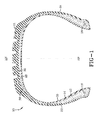
- plies 12, 14 are shown within an example pneumatic tire 10 with a radial carcass wherein like elements have received like reference numerals.
- the example tire 10 has a radial ply carcass structure when the cords of the carcass reinforcing ply, or plies 12, 14 are oriented at angles in the range of 75° to 90° with respect to the equatorial plane (EP) of the example tire.
- EP equatorial plane
- Either ply 12, 14 may be reinforced with the metallic cords, rayon, polyester, nylon, or any other suitable reinforcement.
- the metallic cord reinforced carcass ply 12 or 14 may have a layer of steel cords arranged so as to have from about 8 to about 20 ends per 2.54 cm (EPI) when measured in a tire circumferential direction at a location having a maximum width MW.
- the layer of steel cords may be arranged so as to have about 12 to about 16 ends per 2.54 cm (EPI) at the location having the maximum width MW.
- the steel cords may be arranged as to have from 3 to 8 ends per cm (EPC) when measured in a tire circumferential direction at the location having a the tire maximum width MW.
- a high number of ends per inch may include the use of a lower diameter wire for a given strength versus a low number of ends per inch for a higher diameter wire for the same strength. Also, use of a monofilament of a given diameter may require more or less ends per inch depending on the strength of the monofilament wire.
- the pneumatic tire 10 may have a pair of substantially inextensible annular beads 16, 18, which are axially spaced apart from one another. Each of the beads 16, 18 may be located in a bead portion of the pneumatic tire 10, which has exterior surfaces configured to be complimentary to the beads and retaining flanges of a rim (not shown) upon which the pneumatic tire is designed to be mounted.
- Plies 12, 14 may be of side-by-side reinforcing cords of polyester, steel, or other suitable material and extend between the beads 16, 18 with an axially outer portion of the carcass structure folded about each of the beads.
- the carcass ply structure of FIG. 1 comprises two plies 12, 14 of reinforcing material. One or more carcass plies of any suitable material may be employed.
- a layer of a low permeability material 20 may be disposed inwardly of the carcass plies 12, 14, and contiguous to an inflation chamber defined by the pneumatic tire 10 and rim. Elastomeric sidewalls 22, 24 may be disposed axially outward of the carcass structure 12, 14.
- a circumferentially extending belt structure 26 of two layers of belts 28, 30 ( FIG. 1 ), or four layers of belts 28, 30, 32, 34 ( FIG. 2 ), may include steel reinforcing cords 36 as shown in FIG. 3 .
- the belt structure 26 may also include an overlay 38 interposed radially between the belts 28, 30, 32, 34 and the tread 15 ( FIG. 2 ).
- the belt structure 26 of FIGS. 1 and 2 may comprise the example cords 36 having filaments of Ultra Tensile Steel (UT) or Mega Tensile Steel (MT) (as defined above) with diameters in the range of 0.08 mm to 0.35 mm and appropriate lay lengths.
- the cord 36 of FIG. 3 may have a construction of 2x filaments 363.
- the example cord 36 of FIG. 4 may have a construction of 2 + 1 filaments 364.
- the example cord 36 of FIG. 5 may have a construction of 2 + 2 filaments 365.
- the example cord 36 of FIG. 6 may have a construction of 5x filaments 366.
- One example method of achieving UT strength may be the merging of the process as disclosed in US-A-4,960,473 with a carbon rod microalloyed with one or more of the following elements: Cr, Si, Mn, Ni, Cu, V and B.
- One example construction may be C 0.88 to 1.00, Mn 0.30 to 0.50, Si 0.10 to 0.30, Cr 0.10 to 0.40, V 0 to 0.10, Cu 0 to 0.50, Ni 0 to 0.50, and Co 0.20 to 0.10 with the balance being Fe and residuals.
- the resulting rod may then be drawn to a tensile strength equivalent to 4000 MPa @ 0.20 mm.
- Example filaments of 0.30 mm to 0.35 mm diameter UT steel wire may have a cord breaking strength of at least 1,020 Newtons (N), plus or minus 5%.
- One example structure may have two filaments twisted together with a 16.0 mm lay length with these two filaments twisted at a 16.0 mm lay length together in the same twist direction with two other filaments which are untwisted and parallel to each other when twisted together with the twisted filaments.
- This example cord, a 2+2 construction ( FIG. 5 ), may be designated as 2 + 2 x 30 UT or 2 + 2 x 35 UT.
- the 2 + 2 construction may exhibit openness and good rubber penetration resulting from the openness.
- the 0.30 and 0.35 designate the filament diameter in millimeters and the UT designates the material being ultra tensile steel.
- UT and MT cord structure may perform similar to higher gauge HT and ST steel constructions.
- these example cord structures incorporate filaments having a smaller diameter than those of the HT and ST cord structures, the resulting reduction in gauge material and cost as compared with the HT and ST cord structures results in lighter weight and less costly tires.
- the UT and MT cords have higher strength and generally higher fatigue life over the predecessor HT and ST cords. These advantages lead to elastomer products which have less reinforcement material and thus lower weight and cost. Additionally, the life of the product may be increased with the increase in fatigue life of such cords 36 and filaments 363, 364, 365, 366, as shown in US-A-7,082,978 .
- a parameter which may be varied in a reinforced composite of elastomer is the end count in end per 2.54 cm (EPI), i.e., the number of cords per unit length in the lateral direction to the direction in which the elastomer is being reinforced.
- EPI end per 2.54 cm
- the increased strength of the UT and MT samples may allow a reduction in EPI to achieve comparable strength.
- cord diameter may be reduced and the end count maintained or increased to achieve comparable strength.
- a minimum rivet of 0.018" (0.46 mm) may be maintained to provide proper penetration of elastomers between embedded cords. The penetration may be further enhanced by smaller diameter and simpler (less filaments in a cord) cord constructions made achievable by UT and MT steel filaments.
- UT constructions such as those of FIGS. 3-6 , with diameters, for example, of 0.185 mm or 0.21 mm, provide a lighter weight and less costly alternative for belt constructions of light tires. Further, the reduced weight and cost provide equal to better plant processability (calendering) as well as tire performance greater than conventional constructions.
- a belt structure 26 of UT or MT steel cords 36 produces excellent fatigue performance in a pneumatic tire 10 as well as allowing use of less material in the belt and other parts of the pneumatic tire 10.
- the use of TRIPLEX steel for reinforcement wires (i.e., in the beads, in one or more plies, in the belt, etc.) in a tire or pneumatic tire, in accordance with the present invention would provide even greater advantages in tires, since a weight reduction can be achieved with TRIPLEX steel while maintaining equivalent strength characteristics.
- a TRIPLEX steel bead bundle for an aircraft or truck tire would provide similar strength, but less weight.
- Weight reduction of pneumatic tires is generally limited by a required minimum amount of material. However, with TRIPLEX steel, required strength may be achieved with less weight. For example, a truck tire with TRIPLEX steel beads may weigh 13% less, or 500 Grams less total tire weight.
- High-strength, light weight TRIPLEX steels generally comprise the generic composition Fe-xMn-yAl-zC containing 18 - 28 % manganese, 9 - 12 % aluminum, and 0.7 - 1.2 % C (in mass %).
- the microstructure may be composed of an austenitic ⁇ -Fe(Mn, Al, C) solid solution matrix possessing a fine dispersion of nano-size K-carbides (Fe,Mn) 3 AlC 1-x and ⁇ -Fe(Al, Mn) ferrite of varying volume fractions.
- the austenite is very stable and no strain induced e-martensite may be formed. Mechanical twinning is almost inhibited during plastic deformation.
- the TRIPLEX steels exhibit low density of 6.5 to 7.0 g/cm 3 and superior mechanical properties, such as high strength of 700 to 1100 MPa and total elongations up to 60 % and more.
- the specific energy absorption achieved at high strain rates of 10 3 s -1 is 0.43 J/mm 3 .
- TEM investigations have revealed that homogeneous shear band formation, accompanied by dislocation glide, has occurred in deformed tensile samples.
- the dominant deformation mechanism of TRIPLEX steels is shear band induced plasticity (SIP effect) sustained by a uniform arrangement of nano-size K-carbides coherent to the austenitic matrix.
- SIP effect shear band induced plasticity sustained by a uniform arrangement of nano-size K-carbides coherent to the austenitic matrix.
- the high flow stresses and tensile strengths are caused by effective solid solution hardening and superimposed dispersion strengthening.
- Such ferritic, high aluminum steels provide pronounced reduction of the specific weight based on the high solubility of Al in the cubic centered iron lattice and the strong solid solution strengthening of about 40 MPa per wt % Al. Due to the formation of the k-phase below 400°C, the maximum Al content is restricted to about 6.5 wt %. At this Al content, the reduction of density is about 9%.
- the cold forming limit is widely expanded by micro alloying with B, Nb, and Ti metals to avoid embrittling carbides at grain boundaries.
- the density reduction may be achieved by alloying with the lightweight or lattice expanding Al and Si elements.
- High Mn contents between 15 and 30 wt % may stabilize the austenite.
- the stacking fault energies (SFE's) of the Mn-Al-Si-steels can vary to generate different deformation mechanisms: Transformation Induced Plasticity by martensitic transformation and Twinning Induced Plasticity.
- TRIPLEX steels on base of the quaternary Fe-Mn-Al-C construction combine the above presented alloy concepts.
- Such TRIPLEX steels possess about 15 % lower density, superior strength properties, improved corrosion behavior, and high tensile ductility in comparison with conventional deep drawing steels due to their chemistry, microstructure, deformation, and strengthening mechanisms.
- the TRIPLEX microstructure consists of austenite, ferrite, and nano-dispersed (Fe, Mn) 3Al-C k-carbides. The morphology and distribution of these carbides are strongly influenced by the alloying elements, although the thermal treatment may significantly affect their mechanical properties.
- Fig. 7 shows the stress strain curves of TRIP, TWIP, and TRIPLEX steels
- high strength alloys constituted on the Fe-Mn-Al-C basis represent one of the high manganese alloys of a generation known as TRIPLEX, having the face centered cubic (FCC) microstructure, with predominantly 8% ferrite and 6-9 % nano-size k-carbides being dispersed in a FCC solid solution matrix.
- FCC face centered cubic
- TRIPLEX alloy consists of the FCC matrix characterized by annealing twins, about 8 % ferrite and nano-size k-carbides regularly distributed in the FCC matrix and having a regularly arranged FCC structure. For optimal properties, an additional aging application may be utilized thereby contributing to regular k-carbide precipitation demanded for subsequent realization of a specific deformation mechanism (SIP effect).
- SIP effect a specific deformation mechanism
- Transformation into martensite is also suppressed due to relatively high stacking fault energy (SFE) being about 110 mJ/m 2 .
- SFE stacking fault energy
- the high SFE level is also a reason for no mechanical twinning susceptibility of the TRIPLEX alloy. It has been found that the tendency toward the e-marternsite occurs when the SFE is lower than 15-20 mJ/m 2 .
- the detected modification of the SFE level and e-marternsite transformation resistance (HCP crystallographic lattice) is cause by aluminum (Al) addition to the basic solid solution with manganese (Mn) thereby increasing the SFE and suppressing deformation twinning generally.
- Reduction of specific density occurs due to Al and Mn solubility levels in the FCC matrix and to Al's and Mn's higher atomic radius in comparison with iron's (Fe's) atomic radius.
- Fe's iron's
- the FCC matrix density corresponds to the 6.5 g/cm 3 .
- General weight decreasing of the coexisting FCC and base centered cubic (BCC) phases in solid solution leads to a reduction of average molar weight of the alloy matrix and to a decreasing of unite cell molar density.
- the TRIPLEX microstructure may consist of ferrite (6-8%) and nano-size k-carbides precipitating in the FCC matrix and showing regular arrangement (see L12 below) with central situated C-atom.
- Unite cell may be expressed as (FeMn)3AlC.
- Average lattice parameter level a0 0.3857 nm and is mainly dependent on Al content in the alloy.
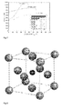
- the k-carbide lattice is represented in Fig. 8 (unit k-carbide cell (L12 type)).
- Twinning deformation and martensite phase transformation realized in high manganese alloys may be replaced by uniformly arranged shear band formation on the ⁇ 111 ⁇ planes of highest density within the FCC matrix.
- SIP-effect shear band induced plasticity Due to above given positive free enthalpy value (+1755 J/mol 1 ) for martensite transformation and due to relatively high SFE (approximately 110 mJ/m 2 ), TRIPLEX alloys may not be prone to martensite transformation or to severe mechanical twinning.
- microstructural analysis of the k-carbide precipitation morphology demonstrates regular distribution of nano-size particles of this phase coherent to the FCC matrix. This finding confirms the important role of the above discussed k-carbides distribution in the FCC matrix by influence of the uniformly arranged shear bands contributing to the strengthening of the TRIPLEX alloy.
- Fig. 10 the specific energy absorptions (EVspec) defined as dissipative energy per unit volume at high strain rate of 102 - 103 s -1 (at the conditions relevant to the crash modeling) of the chosen material types are compared.
- EVspec specific energy absorptions
- two variants of high Mn alloy and four steel types applied as deep drawing materials are indicated.
- the comparison shows the absorption energy of the conventional deep drawing steels is lower than the absorption level of TWIP and TRIPLEX alloys.
- the absorption capacity of these alloys is more than double in comparison with the considered deep drawing steel types.
- These higher absorption values of the above mentioned alloys reflect a higher stress flow and a beneficial plastic elongation level.
- TRIPLEX alloy a significant role in the absorption capacity may be attributed to the effect of severe shear band formation at high strain rate.
- the TRIPLEX alloy Fe-26/30Mn-10/12Al-0.9/1.2C mainly consists of the FCC microstructure with a dispersion of nano-size k-carbides (L12 above) and partially ordered ⁇ -ferrite.
- the chemical composition of the k-carbide is (FeMn)3AlC.
- High energy absorption level (EVspec) of the high Mn alloys represents the beneficial effect of Mn. Contribution of the deformation mechanism to the enhanced ductility is connected with the SIP-effect (shear band induced plasticity). The homogeneous shear band formation may be accompanied by dislocation glide.
- the realization of this mechanism depends on uniform arrangement formation of the nano-size k-carbides being coherent to the FCC matrix.
- the TRIPLEX alloy due to its reduction in specific weight, high strength, and desirable formability including superior crash resistance, may have many applications, such as weight saving structures in pneumatic tires. For example, utilization of the TRIPLEX alloy for a bead bundle, especially for aircraft and trucks, may provide excellent results.
- the beads could weigh 13% less. This provides a savings of 500 gms, or more than one pound, of total tire weight.
- the lower density (about 15 %), superior strength properties, improved corrosion behavior, and high tensile ductility of TRIPLEX steel in comparison with conventional deep drawing steels (UT, MT) are provided by the specific chemistry, microstructures, deformation and strength mechanism of TRIPLEX steel.
- a bead structure 16, 18, ply structure 12, 14, or belt structure 26 with TRIPLEX steel cords 36 in accordance with the present invention produces a lighter weight pneumatic tire 10 without sacrificing strength.
- These structures 12, 14, 16, 18, 26 thus enhance the performance of the tire pneumatic 10, even though the complexities of the structure and behavior of the pneumatic tire are such that no complete and satisfactory theory has been propounded.
- a pneumatic tire has certain essential structural elements. United States Department of Transportation, Mechanics of Pneumatic Tires, pages 207-208 (1981 ). An important structural element is the belt structure, typically made up of many cords of fine hard drawn steel or other metal embedded in, and bonded to, a matrix of low modulus polymeric material, usually natural or synthetic rubber. Id . at 207 through 208.
- the belt structure cord characteristics affect the other components of a pneumatic tire (i.e., belt structure affects apex, carcass ply, overlay, etc.), leading to a number of components interrelating and interacting in such a way as to affect a group of functional properties (noise, handling, durability, comfort, high speed, and mass), resulting in a completely unpredictable and complex composite.
- changing one component can lead to directly improving or degrading many other functional characteristics, as well as altering the interaction between that one component and many other structural components. Each of those interactions may thereby indirectly improve or degrade those ten functional characteristics.
Landscapes
- Engineering & Computer Science (AREA)
- Mechanical Engineering (AREA)
- Tires In General (AREA)
Abstract
Description
- The present invention relates to a tire, preferably a pneumatic tire, comprising a reinforcement structure.
- Reinforced elastomeric articles are well known. For example, conveyor or like type belts, tires, etc., are constructed with cords of textile and/or fine steel wire filaments or strands. In particular, belts used in pneumatic tires are constructed of up to eight ply layers with the cord reinforcement of adjacent plies being biased with respect to the direction of movement of the tire where it is desired to reinforce in both the lateral direction and the direction of rotation of the tire. Further, cords made of strands of multi-twisted filaments of fine wire with a single strand construction having two or more filaments and a wrap filament thereabout to reinforce the cord structure are known.
- In some cases, the reinforcement includes the use of single strand cords of multi-filaments which are not twisted about each other but rather twisted altogether as a bundle or bunch (bunched cord) to simplify the cord construction. Higher fatigue life requirements for composites in tires have resulted in cords with smaller filament diameter, requiring more filaments in the cord to obtain the necessary strength.
- Conventional two ply tire belt structures for passenger and light truck tires may have cords of 2 x 0.255 ST and 2 + 2 x 0.32-0.40 ST, respectively. This designation means one cord of two 0.255 mm diameter filaments and one cord of four 0.32-0.40 mm diameter filaments (with two filaments twisted at a shorter lay length than the other two filaments), respectively. Multi-filament cords such as 2 + 2 x 0.32-0.40 ST have been found necessary to meet the higher demand for strength of composites in tire belts, such as in light truck applications. Both of these cords are made of super tensile (ST) steel as defined hereinafter. Though cord designs incorporating super tensile (ST) steel have proven effective, there is a continuing need to develop lighter weight cord constructions with improved characteristics, such as higher corrosion propagation resistance and improved tire performance, over conventional high tensile (HT) and super tensile (ST) constructions.
- These conventional cord constructions generally have not found use in larger tires, such as off-the-road (OTR) tires. Large OTR tires conventionally use constructions such as 7 x 7 x 0.25 + 1 HT and 3 x 7 x 0.22 HT comprising seven strands each of seven 0.25 mm diameter high tensile (HT) filaments that are twisted together and spiral-wrapped; and three strands each of seven 0.22 mm diameter high tensile (HT) filaments that are twisted together, respectively. One conventional steel cord cable used for ply reinforcement in OTR tires for sizes 36R51 and larger is stranded cord of high tensile (HT) tire cord filament such as 7 x 19 x 0.20 + 1 HT cord comprising seven strands each of nineteen 0.20 mm diameter high tensile (HT) filaments that are twisted together and spiral-wrapped.
- OTR tires may also be constructed of multiple belts or a single belt with reinforcing cords such as 27 x 0.265 ST or 5 + 8 + 14 x 0.265 + 1 ST. Still, conventional steel cord constructions have breaking load and cable gauge limitations preventing the needed design inch-strength from being achieved for tires larger than 40R57 used on trucks and earthmovers weighing up to and sometimes more than 320 tons. In addition, there is a need to increase the rivet area in the ply and belt, i.e., the space between the cords, for tire sizes of 36R51 and larger so that more rubber may penetrate between the cords during tire manufacture to enhance the quality of calendered treatment by preventing "weak rivet" or "loose coat" (which can result in trapped air in tires).
- The higher strength steel alloys have resulted in changes in cord modulus giving rise to the possibility of adjusting the parameters of a tire belt gross load, which depends upon three factors assuming adequate cord to rubber adhesion. The factors are cord modulus, the ratio of cord volume to rubber volume (often expressed as the number of cord ends per 2.54 cm (epi)), and the angle of cord reinforcement. Further, as the angle of cord reinforcement approaches the direction of rotation of the tire, the support from the reinforcement in the lateral direction moves toward zero. An increase in the above-mentioned two other cord related factors, i.e., the cord modulus and the ratio of cord volume to rubber volume, generally results in an increase of weight for the belt. Added weight can mean added cost, higher rolling resistance, and lower fuel economy of a tire. Simply using lighter cords with a lower modulus does not solve the problem because, even though they have lower weight, the lower cord modulus must be offset by increasing the ratio of cord to rubber volume. This increase in cord volume is limited by the physical size of the cord and the resulting spacing between the cords, which governs the amount of rivet, i.e., the ability of the rubber to penetrate between the cords for good cord to rubber adhesion.
-
- "Axial" and "axially" are used herein to refer to lines or directions that are parallel to the axis of rotation of the tire.
- "Cable" means a cord formed by twisting together two or more plied yarns.
- "Carcass" means the tire structure apart from the belt structure, tread, undertread, and sidewall rubber over the plies, but including the beads.
- "Circumferential" means lines or directions extending along the perimeter of the surface of the annular tire parallel to the Equatorial Plane (EP) and perpendicular to the axial direction.
- "Cord" means one of the reinforcement strands which a reinforcement structure of the tire comprises.
- "Denier" means the weight in grams per 9000 meters (unit for expressing linear density). Dtex means the weight in grams per 10,000 meters.
- "Density" means weight per unit length.
- "Fabric" means a network of essentially unidirectionally extending cords, which may be twisted, and which in turn are composed of a plurality of a multiplicity of filaments (which may also be twisted) of a high modulus material.
- "Fiber" is a unit of matter, either natural or man-made that forms the basic element of filaments. It has a length at least 100 times its diameter or width.
- "Filament count" means the number of filaments that make up a yarn. Example: 1000 denier polyester has approximately 190 filaments.
- "High Tensile Steel (HT)" means a carbon steel with a tensile strength of at least 3400 MPa @ 0.20 mm filament diameter.
- "LASE" is load at specified elongation.
- "Lateral" means an axial direction.
- "Lay length" means the distance at which a twisted filament or strand travels to make a 360 degree rotation about another filament or strand.
- "Mega Tensile Steel (MT)" means a carbon steel with a tensile strength of at least 4500 MPa @ 0.20 mm filament diameter.
- "Normal Tensile Steel (NT)" means a carbon steel with a tensile strength of at least 2800 MPa @ 0.20 mm filament diameter.
- "Ply" means a cord-reinforced layer of rubber-coated, preferably radially deployed or otherwise parallel, cords.
- "Radial" and "radially" are used to mean directions radially toward or away from the axis of rotation of the tire.
- "Rivet" means an open space between cords in a layer.
- "Super Tensile Steel (ST)" means a carbon steel with a tensile strength of at least 3650 MPa @ 0.20 mm filament diameter.
- "Tenacity" is stress expressed as force per unit linear density of the unstrained specimen (gm/tex or gm/denier).
- "Tensile" is stress expressed in forces/cross-sectional area. Strength in psi=12,800 times specific gravity times tenacity in grams per denier.
- "Ultra Tensile Steel (UT)" means a carbon steel with a tensile strength of at least 4000 MPa @ 0.20 mm filament diameter.
- "Yarn" is a generic term for a continuous strand of textile fibers or filaments. Yarn occurs in the following forms: 1) a number of fibers twisted together; 2) a number of filaments laid together without twist; 3) a number of filaments laid together with a degree of twist; 4) a single filament with or without twist (monofilament); 5) a narrow strip of material with or without twist.
- The invention relates to a tire in accordance with claim 1.
- Dependent claims refer to preferred embodiments of the invention.
- In a preferred aspect of the invention, the tire is a pneumatic tire and includes a carcass structure, two sidewalls spaced apart a distance, two beads, a tread disposed radially outward of a crown of the carcass structure, a belt structure interposed radially between the carcass structure and the tread, and a reinforcement structure having cords of ferritic high aluminum TRIPLEX steel.
-
-
FIG. 1 is a schematic representation of a cross section of an example embodiment of a pneumatic tire for use with the present invention; -
FIG. 2 is a schematic representation of a partial cross section of a second example embodiment of a pneumatic tire for use with the present invention; -
FIG. 3 is a schematic representation of a cross section of an example reinforcing cord in accordance with the present invention; -
FIG. 4 is a schematic representation of a cross section of another example reinforcing cord in accordance with the present invention; -
FIG. 5 is a schematic representation of a cross section of still another example reinforcing cord in accordance with the present invention; -
FIG. 6 is a schematic representation of a cross section of yet another example reinforcing cord in accordance with the present invention; -
FIG. 7 shows the stress strain curves of TRIP, TWIP, and TRIPLEX steels; -
FIG. 8 represents the k-carbide lattice (unit k-carbide cell (L12 type)); -
FIG. 9 shows engineering stress-strain curves of thermally aged TRIPLEX alloy; and -
FIG. 10 shows specific energy absorption (EV spec) of high Mn alloys and conventional deep drawing steels (crash modeling). - Referring to
FIGS. 1 and2 , plies 12, 14 are shown within an examplepneumatic tire 10 with a radial carcass wherein like elements have received like reference numerals. Theexample tire 10 has a radial ply carcass structure when the cords of the carcass reinforcing ply, or plies 12, 14 are oriented at angles in the range of 75° to 90° with respect to the equatorial plane (EP) of the example tire. - Either ply 12, 14 may be reinforced with the metallic cords, rayon, polyester, nylon, or any other suitable reinforcement. The metallic cord reinforced carcass ply 12 or 14 may have a layer of steel cords arranged so as to have from about 8 to about 20 ends per 2.54 cm (EPI) when measured in a tire circumferential direction at a location having a maximum width MW. For example, the layer of steel cords may be arranged so as to have about 12 to about 16 ends per 2.54 cm (EPI) at the location having the maximum width MW. In terms of metric units, the steel cords may be arranged as to have from 3 to 8 ends per cm (EPC) when measured in a tire circumferential direction at the location having a the tire maximum width MW. A high number of ends per inch may include the use of a lower diameter wire for a given strength versus a low number of ends per inch for a higher diameter wire for the same strength. Also, use of a monofilament of a given diameter may require more or less ends per inch depending on the strength of the monofilament wire.
- The
pneumatic tire 10 may have a pair of substantially inextensibleannular beads beads pneumatic tire 10, which has exterior surfaces configured to be complimentary to the beads and retaining flanges of a rim (not shown) upon which the pneumatic tire is designed to be mounted.Plies beads FIG. 1 comprises twoplies - A layer of a
low permeability material 20 may be disposed inwardly of the carcass plies 12, 14, and contiguous to an inflation chamber defined by thepneumatic tire 10 and rim. Elastomeric sidewalls 22, 24 may be disposed axially outward of thecarcass structure belt structure 26 of two layers ofbelts 28, 30 (FIG. 1 ), or four layers ofbelts FIG. 2 ), may includesteel reinforcing cords 36 as shown inFIG. 3 . Thebelt structure 26 may also include anoverlay 38 interposed radially between thebelts FIG. 2 ). - The
belt structure 26 ofFIGS. 1 and2 may comprise theexample cords 36 having filaments of Ultra Tensile Steel (UT) or Mega Tensile Steel (MT) (as defined above) with diameters in the range of 0.08 mm to 0.35 mm and appropriate lay lengths. For example, thecord 36 ofFIG. 3 may have a construction of2x filaments 363. Theexample cord 36 ofFIG. 4 may have a construction of 2 + 1filaments 364. Theexample cord 36 ofFIG. 5 may have a construction of 2 + 2filaments 365. Theexample cord 36 ofFIG. 6 may have a construction of5x filaments 366. - One example method of achieving UT strength may be the merging of the process as disclosed in
US-A-4,960,473 with a carbon rod microalloyed with one or more of the following elements: Cr, Si, Mn, Ni, Cu, V and B. One example construction may be C 0.88 to 1.00, Mn 0.30 to 0.50, Si 0.10 to 0.30, Cr 0.10 to 0.40,V 0 to 0.10,Cu 0 to 0.50,Ni 0 to 0.50, and Co 0.20 to 0.10 with the balance being Fe and residuals. The resulting rod may then be drawn to a tensile strength equivalent to 4000 MPa @ 0.20 mm. - Example filaments of 0.30 mm to 0.35 mm diameter UT steel wire may have a cord breaking strength of at least 1,020 Newtons (N), plus or minus 5%. One example structure may have two filaments twisted together with a 16.0 mm lay length with these two filaments twisted at a 16.0 mm lay length together in the same twist direction with two other filaments which are untwisted and parallel to each other when twisted together with the twisted filaments. This example cord, a 2+2 construction (
FIG. 5 ), may be designated as 2 + 2 x 30 UT or 2 + 2 x 35 UT. The 2 + 2 construction may exhibit openness and good rubber penetration resulting from the openness. The 0.30 and 0.35 designate the filament diameter in millimeters and the UT designates the material being ultra tensile steel. - The above examples of UT and MT cord structure may perform similar to higher gauge HT and ST steel constructions. Thus, when these example cord structures incorporate filaments having a smaller diameter than those of the HT and ST cord structures, the resulting reduction in gauge material and cost as compared with the HT and ST cord structures results in lighter weight and less costly tires.
- Further, for equal filament diameters, the UT and MT cords have higher strength and generally higher fatigue life over the predecessor HT and ST cords. These advantages lead to elastomer products which have less reinforcement material and thus lower weight and cost. Additionally, the life of the product may be increased with the increase in fatigue life of
such cords 36 andfilaments US-A-7,082,978 . - A parameter which may be varied in a reinforced composite of elastomer is the end count in end per 2.54 cm (EPI), i.e., the number of cords per unit length in the lateral direction to the direction in which the elastomer is being reinforced. The increased strength of the UT and MT samples may allow a reduction in EPI to achieve comparable strength. Alternatively, cord diameter may be reduced and the end count maintained or increased to achieve comparable strength. Further, a minimum rivet of 0.018" (0.46 mm) may be maintained to provide proper penetration of elastomers between embedded cords. The penetration may be further enhanced by smaller diameter and simpler (less filaments in a cord) cord constructions made achievable by UT and MT steel filaments.
- UT constructions, such as those of
FIGS. 3-6 , with diameters, for example, of 0.185 mm or 0.21 mm, provide a lighter weight and less costly alternative for belt constructions of light tires. Further, the reduced weight and cost provide equal to better plant processability (calendering) as well as tire performance greater than conventional constructions. - As stated above, a
belt structure 26 of UT orMT steel cords 36 produces excellent fatigue performance in apneumatic tire 10 as well as allowing use of less material in the belt and other parts of thepneumatic tire 10. However, the use of TRIPLEX steel for reinforcement wires (i.e., in the beads, in one or more plies, in the belt, etc.) in a tire or pneumatic tire, in accordance with the present invention, would provide even greater advantages in tires, since a weight reduction can be achieved with TRIPLEX steel while maintaining equivalent strength characteristics. For example, a TRIPLEX steel bead bundle for an aircraft or truck tire would provide similar strength, but less weight. - Weight reduction of pneumatic tires is generally limited by a required minimum amount of material. However, with TRIPLEX steel, required strength may be achieved with less weight. For example, a truck tire with TRIPLEX steel beads may weigh 13% less, or 500 Grams less total tire weight.
- With the properties of TRIPLEX steel, and the corresponding less weight, other benefits, such as reduced rolling resistance, may also be achieved in tires. High-strength, light weight TRIPLEX steels generally comprise the generic composition Fe-xMn-yAl-zC containing 18 - 28 % manganese, 9 - 12 % aluminum, and 0.7 - 1.2 % C (in mass %). The microstructure may be composed of an austenitic γ-Fe(Mn, Al, C) solid solution matrix possessing a fine dispersion of nano-size K-carbides (Fe,Mn)3AlC1-xand α-Fe(Al, Mn) ferrite of varying volume fractions. The calculated Gibbs free energy of the phase transformation γfcc → Ehcp amounts to ΔGγ→E = 1757 J/mol and the stacking fault energy was determined FSF =110 mJ/m2. Thus, the austenite is very stable and no strain induced e-martensite may be formed. Mechanical twinning is almost inhibited during plastic deformation. The TRIPLEX steels exhibit low density of 6.5 to 7.0 g/cm3 and superior mechanical properties, such as high strength of 700 to 1100 MPa and total elongations up to 60 % and more. The specific energy absorption achieved at high strain rates of 103 s-1 is 0.43 J/mm3. TEM investigations have revealed that homogeneous shear band formation, accompanied by dislocation glide, has occurred in deformed tensile samples. The dominant deformation mechanism of TRIPLEX steels is shear band induced plasticity (SIP effect) sustained by a uniform arrangement of nano-size K-carbides coherent to the austenitic matrix. The high flow stresses and tensile strengths are caused by effective solid solution hardening and superimposed dispersion strengthening.
- Such ferritic, high aluminum steels provide pronounced reduction of the specific weight based on the high solubility of Al in the cubic centered iron lattice and the strong solid solution strengthening of about 40 MPa per wt % Al. Due to the formation of the k-phase below 400°C, the maximum Al content is restricted to about 6.5 wt %. At this Al content, the reduction of density is about 9%. The cold forming limit is widely expanded by micro alloying with B, Nb, and Ti metals to avoid embrittling carbides at grain boundaries.
- In transformation induced plasticity (TRIP) and twinning induced plasticity (TWIP) steels, the density reduction may be achieved by alloying with the lightweight or lattice expanding Al and Si elements. High Mn contents between 15 and 30 wt % may stabilize the austenite. In the composition range from 1.5 to 4 wt % Al and Si, the stacking fault energies (SFE's) of the Mn-Al-Si-steels can vary to generate different deformation mechanisms: Transformation Induced Plasticity by martensitic transformation and Twinning Induced Plasticity.
- TRIPLEX steels on base of the quaternary Fe-Mn-Al-C construction combine the above presented alloy concepts. Such TRIPLEX steels possess about 15 % lower density, superior strength properties, improved corrosion behavior, and high tensile ductility in comparison with conventional deep drawing steels due to their chemistry, microstructure, deformation, and strengthening mechanisms. The TRIPLEX microstructure consists of austenite, ferrite, and nano-dispersed (Fe, Mn) 3Al-C k-carbides. The morphology and distribution of these carbides are strongly influenced by the alloying elements, although the thermal treatment may significantly affect their mechanical properties. Pronounced homogeneous shear-band formation causes Shear-band Induced Plasticity (SIP effect) and the high-strength properties are due to effective solid solution hardening and dislocation interactions in crossing shear bands. The extraordinary ductility and toughness of TRIPLEX steel, even under impact loading, promotes high energy absorption at very high strain rates (up to 103 s-1).
Fig. 7 shows the stress strain curves of TRIP, TWIP, and TRIPLEX steels - Thus, high strength alloys constituted on the Fe-Mn-Al-C basis represent one of the high manganese alloys of a generation known as TRIPLEX, having the face centered cubic (FCC) microstructure, with predominantly 8% ferrite and 6-9 % nano-size k-carbides being dispersed in a FCC solid solution matrix.
- TRIPLEX alloy consists of the FCC matrix characterized by annealing twins, about 8 % ferrite and nano-size k-carbides regularly distributed in the FCC matrix and having a regularly arranged FCC structure. For optimal properties, an additional aging application may be utilized thereby contributing to regular k-carbide precipitation demanded for subsequent realization of a specific deformation mechanism (SIP effect). Such TRIPLEX alloys may be resistant to e-martensite transformation. Namely, positive free enthalpy austenite decomposition into e-martensite (ΔGyγ→e = +1755 J.mol-1) is a reason for the high FCC matrix stability. Transformation into martensite is also suppressed due to relatively high stacking fault energy (SFE) being about 110 mJ/m2. The high SFE level is also a reason for no mechanical twinning susceptibility of the TRIPLEX alloy. It has been found that the tendency toward the e-marternsite occurs when the SFE is lower than 15-20 mJ/m2. The detected modification of the SFE level and e-marternsite transformation resistance (HCP crystallographic lattice) is cause by aluminum (Al) addition to the basic solid solution with manganese (Mn) thereby increasing the SFE and suppressing deformation twinning generally. Reduction of specific density occurs due to Al and Mn solubility levels in the FCC matrix and to Al's and Mn's higher atomic radius in comparison with iron's (Fe's) atomic radius. For example, in an alloy of 12% Al and 28% Mn, the FCC matrix density corresponds to the 6.5 g/cm3. General weight decreasing of the coexisting FCC and base centered cubic (BCC) phases in solid solution leads to a reduction of average molar weight of the alloy matrix and to a decreasing of unite cell molar density. The matrix lattice will be larger, resulting from the Al and Mn atomic radii (rAl = 0.147 nm, rMn = 0.134 nm) in comparison with the Fe atoms (rFe = 0.126 nm). Beside the basic FCC phase, the TRIPLEX microstructure may consist of ferrite (6-8%) and nano-size k-carbides precipitating in the FCC matrix and showing regular arrangement (see L12 below) with central situated C-atom. Unite cell may be expressed as (FeMn)3AlC. Average lattice parameter level a0 = 0.3857 nm and is mainly dependent on Al content in the alloy. The k-carbide lattice is represented in
Fig. 8 (unit k-carbide cell (L12 type)). - Twinning deformation and martensite phase transformation realized in high manganese alloys may be replaced by uniformly arranged shear band formation on the {111} planes of highest density within the FCC matrix. These features represent an significant contribution to homogeneous shear deformation to the large plastic elongation known as the SIP-effect (shear band induced plasticity). Due to above given positive free enthalpy value (+1755 J/mol1) for martensite transformation and due to relatively high SFE (approximately 110 mJ/m2), TRIPLEX alloys may not be prone to martensite transformation or to severe mechanical twinning.
- The microstructural analysis of the k-carbide precipitation morphology demonstrates regular distribution of nano-size particles of this phase coherent to the FCC matrix. This finding confirms the important role of the above discussed k-carbides distribution in the FCC matrix by influence of the uniformly arranged shear bands contributing to the strengthening of the TRIPLEX alloy.
- Engineering stress-strain curves of high Mn-Al TRIPLEX alloy at test temperatures between -100°C and 400°C illustrate distinct strain hardening and a different deformation mechanism in the temperature interval. The best plastic strain (εpl) of about 53% was detected at 20°C (strength reached 1100 MPa). With the higher temperature, the εpl increased along with strength (at 400°C for εpl = 19 %, strength was 700 MPa). The lower test temperature was chosen, the higher stress level was reached along with the worst εpl (at -100°C for εpl = 37 % , the strength was 1260 MPa). Results are summarized in Table 1 below. In order to increase the mechanical characteristics in strength level without plastic response degradation, particularly, the investigated alloy is usually subjected to thermal aging at 550°C for different isothermal aging time between 2.1 min and 46 min. The results are summarized in
Figure 9 in the form of engineering curves of aged samples. After prolonged aging time, the Rp (0.2) increase from 700 MPa to 1060 MPa is found (determined at room temperature). The presented stress - strain dependences most similar to those of an ideal elastic (plastic solid where virtually no strain hardening occurs). This demonstrates the desirability of uniform shearing for achieving extended plastic deformation realized by the moderate deformation hardening mechanism.Table I Relationship between stress and strain values of TRIPLEX alloys in neck region (by tensile testing) Testing temperature [°C] Strength [MPa] Plastic strain [%] -100 1260 37 20 1100 53 200 850 44 400 700 19 - Engineering stress-strain curves of thermally aged TRIPLEX alloy are demonstrated in
Fig.9 . Aging was realized at 550°C for different time intervals. - Specific energy absorption (EV spec) of high Mn alloys and conventional deep drawing steels (crash modeling) are shown in
Fig. 10 . - In
Fig. 10 , the specific energy absorptions (EVspec) defined as dissipative energy per unit volume at high strain rate of 102 - 103 s-1 (at the conditions relevant to the crash modeling) of the chosen material types are compared. In the set of the evaluated steels and alloys, two variants of high Mn alloy and four steel types applied as deep drawing materials are indicated. The comparison shows the absorption energy of the conventional deep drawing steels is lower than the absorption level of TWIP and TRIPLEX alloys. The absorption capacity of these alloys is more than double in comparison with the considered deep drawing steel types. These higher absorption values of the above mentioned alloys reflect a higher stress flow and a beneficial plastic elongation level. In the TRIPLEX alloy, a significant role in the absorption capacity may be attributed to the effect of severe shear band formation at high strain rate. - The TRIPLEX alloy Fe-26/30Mn-10/12Al-0.9/1.2C mainly consists of the FCC microstructure with a dispersion of nano-size k-carbides (L12 above) and partially ordered α-ferrite. The chemical composition of the k-carbide is (FeMn)3AlC. The achieved superior properties of the TRIPLEX may be attributed to the effective solid solution and precipitation strengthening. High energy absorption level (EVspec) of the high Mn alloys represents the beneficial effect of Mn. Contribution of the deformation mechanism to the enhanced ductility is connected with the SIP-effect (shear band induced plasticity). The homogeneous shear band formation may be accompanied by dislocation glide. The realization of this mechanism depends on uniform arrangement formation of the nano-size k-carbides being coherent to the FCC matrix. The TRIPLEX alloy, due to its reduction in specific weight, high strength, and desirable formability including superior crash resistance, may have many applications, such as weight saving structures in pneumatic tires. For example, utilization of the TRIPLEX alloy for a bead bundle, especially for aircraft and trucks, may provide excellent results.
- On a truck tire with TRIPLEX steel beads, the beads could weigh 13% less. This provides a savings of 500 gms, or more than one pound, of total tire weight. The lower density (about 15 %), superior strength properties, improved corrosion behavior, and high tensile ductility of TRIPLEX steel in comparison with conventional deep drawing steels (UT, MT) are provided by the specific chemistry, microstructures, deformation and strength mechanism of TRIPLEX steel.
- As stated above, a
bead structure structure belt structure 26 withTRIPLEX steel cords 36 in accordance with the present invention produces a lighter weightpneumatic tire 10 without sacrificing strength. Thesestructures tire pneumatic 10, even though the complexities of the structure and behavior of the pneumatic tire are such that no complete and satisfactory theory has been propounded. - A pneumatic tire has certain essential structural elements. United States Department of Transportation, Mechanics of Pneumatic Tires, pages 207-208 (1981). An important structural element is the belt structure, typically made up of many cords of fine hard drawn steel or other metal embedded in, and bonded to, a matrix of low modulus polymeric material, usually natural or synthetic rubber. Id. at 207 through 208.
- The belt structure cord characteristics affect the other components of a pneumatic tire (i.e., belt structure affects apex, carcass ply, overlay, etc.), leading to a number of components interrelating and interacting in such a way as to affect a group of functional properties (noise, handling, durability, comfort, high speed, and mass), resulting in a completely unpredictable and complex composite. Thus, changing one component can lead to directly improving or degrading many other functional characteristics, as well as altering the interaction between that one component and many other structural components. Each of those interactions may thereby indirectly improve or degrade those ten functional characteristics.
- Only through extensive experimentation have the
bead structure structure belt structure 26 of TRIPLEX cords of the present invention been revealed as an excellent, unexpected, and unpredictable option for a pneumatic tire.
Claims (15)
- A tire comprising a reinforcement structure comprising cords of a TRIPLEX steel.
- The tire of claim 1 wherein the TRIPLEX steel is a ferritic high aluminum TRIPLEX steel.
- The tire of claim 1 or 2 wherein the tire is a pneumatic tire comprising a carcass structure, two sidewalls (22, 24), two beads (16, 18), a tread (15) disposed radially outward of a crown of the carcass structure, and a belt structure (26) interposed radially between the carcass structure and the tread (15).
- The tire of at least one of the previous claims wherein the cords comprises filaments with diameters in a range of from 0.18 mm to 0.22 mm.
- The tire of at least one of the previous claims wherein the TRIPLEX steel cords are arranged such that they have from 8 to 20 ends per 2.54 cm.
- The tire as set forth in claim 4 wherein the cords comprises 0.185 mm diameter filaments.
- The tire as set forth in claim 4 wherein the cords comprises 0.21 mm diameter filaments.
- The tire of at least one of the previous claims wherein the cords have a 2 + 1 construction.
- The tire of at least one of the previous claims wherein the cords have a 2 x construction.
- The tire of at least one of the previous claims wherein the cords have a 2 + 2 construction.
- The tire of at least one of the previous claims wherein the cords have a 5 x construction.
- The tire of at least one of the previous claims wherein the carcass structure comprises the reinforcement structure.
- The tire of at least one of the previous claims wherein the beads comprise the reinforcement structure.
- The tire of at least one of the previous claims wherein the belt structure comprises the reinforcement structure.
- The tire of at least one of the previous claims wherein the TRIPLEX steel is of the generic composition FexMnyAlzC containing 18-28 % manganese, 9-12 % aluminum, and 0.7 -1.2 % carbon (in mass %) and/or wherein the TRIPLEX steel is composed of an austenitic γ-Fe(Mn, Al, C) solid solution matrix possessing a fine dispersion of nano-size K-carbides (Fe,Mn)3AlC1-xand α-Fe(Al, Mn) ferrite of varying volume fractions.
Applications Claiming Priority (1)
| Application Number | Priority Date | Filing Date | Title |
|---|---|---|---|
| US12/887,751 US20120067492A1 (en) | 2010-09-22 | 2010-09-22 | Tires with high strength reinforcement |
Publications (1)
| Publication Number | Publication Date |
|---|---|
| EP2434049A1 true EP2434049A1 (en) | 2012-03-28 |
Family
ID=44907732
Family Applications (1)
| Application Number | Title | Priority Date | Filing Date |
|---|---|---|---|
| EP11181627A Withdrawn EP2434049A1 (en) | 2010-09-22 | 2011-09-16 | Tire with high strength reinforcement |
Country Status (6)
| Country | Link |
|---|---|
| US (1) | US20120067492A1 (en) |
| EP (1) | EP2434049A1 (en) |
| JP (1) | JP2012066813A (en) |
| KR (1) | KR20120031149A (en) |
| CN (1) | CN102407739A (en) |
| BR (1) | BRPI1104910A2 (en) |
Families Citing this family (2)
| Publication number | Priority date | Publication date | Assignee | Title |
|---|---|---|---|---|
| KR101379554B1 (en) * | 2012-08-02 | 2014-03-28 | 한국타이어 주식회사 | Truck and Bus Tire with Improved Bead Durability |
| CN114201902B (en) * | 2021-12-27 | 2024-11-01 | 中策橡胶集团股份有限公司 | A method, device and program for predicting the contribution of uniform ground pressure distribution to tire rolling resistance |
Citations (2)
| Publication number | Priority date | Publication date | Assignee | Title |
|---|---|---|---|---|
| US4960473A (en) | 1989-10-02 | 1990-10-02 | The Goodyear Tire & Rubber Company | Process for manufacturing steel filament |
| US7082978B2 (en) | 1994-12-20 | 2006-08-01 | The Goodyear Tire & Rubber Company | Tires with high strength reinforcement |
Family Cites Families (2)
| Publication number | Priority date | Publication date | Assignee | Title |
|---|---|---|---|---|
| US6120911A (en) * | 1997-09-09 | 2000-09-19 | The Goodyear Tire & Rubber Company | Zinc-rich coated steel article |
| EP1430161B1 (en) * | 2001-09-28 | 2005-06-15 | DaimlerChrysler AG | High-strength duplex/triplex steel for lightweight construction and use thereof |
-
2010
- 2010-09-22 US US12/887,751 patent/US20120067492A1/en not_active Abandoned
-
2011
- 2011-09-15 JP JP2011201347A patent/JP2012066813A/en not_active Withdrawn
- 2011-09-16 BR BRPI1104910-3A patent/BRPI1104910A2/en not_active IP Right Cessation
- 2011-09-16 EP EP11181627A patent/EP2434049A1/en not_active Withdrawn
- 2011-09-21 KR KR1020110095313A patent/KR20120031149A/en not_active Ceased
- 2011-09-22 CN CN2011102834150A patent/CN102407739A/en active Pending
Patent Citations (2)
| Publication number | Priority date | Publication date | Assignee | Title |
|---|---|---|---|---|
| US4960473A (en) | 1989-10-02 | 1990-10-02 | The Goodyear Tire & Rubber Company | Process for manufacturing steel filament |
| US7082978B2 (en) | 1994-12-20 | 2006-08-01 | The Goodyear Tire & Rubber Company | Tires with high strength reinforcement |
Non-Patent Citations (3)
| Title |
|---|
| "United States Department of Transportation", MECHANICS OF PNEUMATIC TIRES, 1981, pages 207 - 208 |
| FROMMEYER GEORG; BRÜX UDO: "Microstructures and mechanical properties of high-strength Fe-Mn-Al-C light-weight TRIPLEX steels", STEEL RESEARCH INTERNATIONAL, no. 9-10, 2006, Düsseldorf, Germany, pages 627 - 633, XP002664035, ISSN: 1611-3683, Retrieved from the Internet <URL:http://cat.inist.fr/?aModele=afficheN&cpsidt=18173307> [retrieved on 20111121] * |
| NANOWERK: "Nano-engineered steels for structural applications", 10 February 2010 (2010-02-10), XP002664036, Retrieved from the Internet <URL:http://www.nanowerk.com/spotlight/spotid=16203.php> [retrieved on 20111121] * |
Also Published As
| Publication number | Publication date |
|---|---|
| KR20120031149A (en) | 2012-03-30 |
| JP2012066813A (en) | 2012-04-05 |
| BRPI1104910A2 (en) | 2015-07-21 |
| CN102407739A (en) | 2012-04-11 |
| US20120067492A1 (en) | 2012-03-22 |
Similar Documents
| Publication | Publication Date | Title |
|---|---|---|
| JP3822896B2 (en) | High strength reinforced tire | |
| US6247514B1 (en) | Tires with high strength reinforcement | |
| AU593070B2 (en) | Reinforced composite structure | |
| US20120067487A1 (en) | Tires with high strength reinforcement | |
| EP2433814B1 (en) | Tires with high strengh reinforcement | |
| US20120067492A1 (en) | Tires with high strength reinforcement | |
| US20120067491A1 (en) | Tires with high strength reinforcement | |
| AU642996B2 (en) | High strength cord | |
| US6273160B1 (en) | Tires with high strength reinforcement | |
| EP2380755B1 (en) | Overlay ply covering the belt ply for a pneumatic tire | |
| US6146760A (en) | High strength cord | |
| US20120067490A1 (en) | Tires with high strength reinforcement | |
| JP4450686B2 (en) | Steel cord and tire for rubber reinforcement | |
| JP2012066816A (en) | Tire with high strength reinforcement structure | |
| US20120067488A1 (en) | Tires with high strength reinforcement | |
| CA2317943C (en) | Tires with high strength reinforcement | |
| US20120067489A1 (en) | Tires with high strength reinforcement | |
| JPH0268376A (en) | Radial tire |
Legal Events
| Date | Code | Title | Description |
|---|---|---|---|
| PUAI | Public reference made under article 153(3) epc to a published international application that has entered the european phase |
Free format text: ORIGINAL CODE: 0009012 |
|
| AK | Designated contracting states |
Kind code of ref document: A1 Designated state(s): AL AT BE BG CH CY CZ DE DK EE ES FI FR GB GR HR HU IE IS IT LI LT LU LV MC MK MT NL NO PL PT RO RS SE SI SK SM TR |
|
| AX | Request for extension of the european patent |
Extension state: BA ME |
|
| 17P | Request for examination filed |
Effective date: 20120928 |
|
| 17Q | First examination report despatched |
Effective date: 20130109 |
|
| RIC1 | Information provided on ipc code assigned before grant |
Ipc: B60C 9/20 20060101ALI20130528BHEP Ipc: B60C 9/16 20060101ALI20130528BHEP Ipc: B60C 15/04 20060101ALI20130528BHEP Ipc: B60C 9/00 20060101ALI20130528BHEP Ipc: D07B 1/06 20060101AFI20130528BHEP |
|
| GRAP | Despatch of communication of intention to grant a patent |
Free format text: ORIGINAL CODE: EPIDOSNIGR1 |
|
| INTG | Intention to grant announced |
Effective date: 20130819 |
|
| STAA | Information on the status of an ep patent application or granted ep patent |
Free format text: STATUS: THE APPLICATION IS DEEMED TO BE WITHDRAWN |
|
| 18D | Application deemed to be withdrawn |
Effective date: 20140103 |