EP2433804A1 - Printing device fluid reservoir with gripping features - Google Patents
Printing device fluid reservoir with gripping features Download PDFInfo
- Publication number
- EP2433804A1 EP2433804A1 EP11195094A EP11195094A EP2433804A1 EP 2433804 A1 EP2433804 A1 EP 2433804A1 EP 11195094 A EP11195094 A EP 11195094A EP 11195094 A EP11195094 A EP 11195094A EP 2433804 A1 EP2433804 A1 EP 2433804A1
- Authority
- EP
- European Patent Office
- Prior art keywords
- fluid reservoir
- fluid
- lever
- chassis
- containing body
- Prior art date
- Legal status (The legal status is an assumption and is not a legal conclusion. Google has not performed a legal analysis and makes no representation as to the accuracy of the status listed.)
- Withdrawn
Links
- 239000012530 fluid Substances 0.000 title claims abstract description 205
- 238000007639 printing Methods 0.000 title claims abstract description 26
- 210000003811 finger Anatomy 0.000 description 11
- 239000000976 ink Substances 0.000 description 9
- 239000000758 substrate Substances 0.000 description 6
- 238000003780 insertion Methods 0.000 description 5
- 230000037431 insertion Effects 0.000 description 5
- 230000003993 interaction Effects 0.000 description 4
- 230000008901 benefit Effects 0.000 description 3
- 239000000463 material Substances 0.000 description 3
- 230000001939 inductive effect Effects 0.000 description 2
- 238000002347 injection Methods 0.000 description 2
- 239000007924 injection Substances 0.000 description 2
- 239000004033 plastic Substances 0.000 description 2
- 239000000243 solution Substances 0.000 description 2
- 210000003813 thumb Anatomy 0.000 description 2
- 239000004721 Polyphenylene oxide Substances 0.000 description 1
- 239000004743 Polypropylene Substances 0.000 description 1
- 239000000853 adhesive Substances 0.000 description 1
- 230000001070 adhesive effect Effects 0.000 description 1
- 238000013459 approach Methods 0.000 description 1
- 230000009286 beneficial effect Effects 0.000 description 1
- 238000004891 communication Methods 0.000 description 1
- 230000000994 depressogenic effect Effects 0.000 description 1
- 239000011521 glass Substances 0.000 description 1
- 238000007641 inkjet printing Methods 0.000 description 1
- 238000009434 installation Methods 0.000 description 1
- 238000000034 method Methods 0.000 description 1
- 229920006380 polyphenylene oxide Polymers 0.000 description 1
- -1 polypropylene Polymers 0.000 description 1
- 229920001155 polypropylene Polymers 0.000 description 1
- 238000003466 welding Methods 0.000 description 1
Images


Classifications
-
- B—PERFORMING OPERATIONS; TRANSPORTING
- B41—PRINTING; LINING MACHINES; TYPEWRITERS; STAMPS
- B41J—TYPEWRITERS; SELECTIVE PRINTING MECHANISMS, i.e. MECHANISMS PRINTING OTHERWISE THAN FROM A FORME; CORRECTION OF TYPOGRAPHICAL ERRORS
- B41J2/00—Typewriters or selective printing mechanisms characterised by the printing or marking process for which they are designed
- B41J2/005—Typewriters or selective printing mechanisms characterised by the printing or marking process for which they are designed characterised by bringing liquid or particles selectively into contact with a printing material
- B41J2/01—Ink jet
- B41J2/17—Ink jet characterised by ink handling
- B41J2/175—Ink supply systems ; Circuit parts therefor
- B41J2/17503—Ink cartridges
- B41J2/17513—Inner structure
-
- B—PERFORMING OPERATIONS; TRANSPORTING
- B41—PRINTING; LINING MACHINES; TYPEWRITERS; STAMPS
- B41J—TYPEWRITERS; SELECTIVE PRINTING MECHANISMS, i.e. MECHANISMS PRINTING OTHERWISE THAN FROM A FORME; CORRECTION OF TYPOGRAPHICAL ERRORS
- B41J2/00—Typewriters or selective printing mechanisms characterised by the printing or marking process for which they are designed
- B41J2/005—Typewriters or selective printing mechanisms characterised by the printing or marking process for which they are designed characterised by bringing liquid or particles selectively into contact with a printing material
- B41J2/01—Ink jet
- B41J2/17—Ink jet characterised by ink handling
- B41J2/175—Ink supply systems ; Circuit parts therefor
- B41J2/17503—Ink cartridges
- B41J2/1752—Mounting within the printer
Definitions
- This invention pertains to a printing device fluid reservoir with gripping features.
- this invention pertains to gripping features for a fluid reservoir that facilitate holding, insertion of, and removal of the fluid reservoir from a chassis.
- Fluid-ejection printing devices such as ink jet printers, commonly have at least one fluid reservoir and a chassis that supports the fluid reservoir.
- the combination of the fluid reservoir and the chassis is referred to herein as a "fluid-providing system.”
- the fluid reservoir may contain one or more fluid chambers that provide fluid to a printhead. If the fluid reservoir has more than one ink chamber, each such chamber often retains fluid of a different color for multi-color printing. On the other hand, if the fluid reservoir has only a single ink chamber, typically such chamber is used to retain black ink for black-and-white printing.
- the printhead commonly is connected directly or indirectly to the chassis.
- the printhead along with the chassis and the fluid reservoir, typically are moved in a lateral direction across a width of a substrate, such as paper, as fluid is ejected from the printhead.
- the substrate is advanced in a direction perpendicular to the lateral direction along a length of the substrate, so that the printhead can form a subsequent row-portion of the image. This process of advancing the substrate for each row-portion is repeated until a next substrate is needed or the image is completed.
- the fluid reservoir includes a first surface and a fluid-containing body located beneath the first surface when the fluid reservoir is in an orientation in which it is configured to operate.
- the first surface includes a protruding grip
- the fluid-containing body has a lever extending therefrom.
- both the protruding grip and the lever are configured to receive a pinching force that compresses the lever towards the fluid-containing body, facilitates carrying of the fluid reservoir, and facilitates installing and/or releasing the fluid reservoir into/from a chassis of the printing device.
- the protruding grip extends horizontally or substantially horizontally beyond an edge of the fluid containing body.
- the protruding grip may be flat or substantially flat, which may make the fluid reservoir easier to fit into a printing device. Further in this regard, the protruding grip and the first surface of the fluid reservoir form a single flat or substantially flat surface, which also may make the fluid reservoir easier to fit into a printing device.
- the protruding grip may be curved (along with or separate from the first surface of the fluid reservoir) to facilitate better interaction with a finger applying a pinching force. Further, the protruding grip may include a textured region to facilitate gripping and interaction with a finger applying the pinching force.
- the lever extending from the fluid-containing body may be located at least in part beneath the protruding grip when the fluid reservoir is in an orientation in which it is configured to operate.
- the lever may extend further from the fluid-containing body than the protruding grip does.
- the lever may extend the same or substantially the same distance from the fluid-containing body or less than the distance from the fluid-containing body than the protruding grip does.
- the lever is configured to retain a finger by its shape.
- the lever may have a pinching-force-reception region that is concave to assist it in facilitating reception of a finger applying the pinching force.
- the lever and, optionally, the chassis are formed of a material and/or are arranged in a configuration that generates an audible sound when the fluid reservoir is properly inserted into the chassis of the printing device.
- a user receives instant and audible feedback regarding when the fluid reservoir is properly inserted into the chassis.
- sensing devices may be included with the printing device to monitor and determine whether such an audible click has been produced, in order to determine whether the fluid reservoir has been properly inserted into the supporting chassis.
- Embodiments of the present invention provide a protruding grip and lever combination configured to receive a pinching force, by which the fluid reservoir may easily be carried, inserted into a supporting chassis, or removed from the supporting chassis.
- additional features such as a flat or substantially flat protruding grip, a curved protruding grip, texture on the protruding grip, a proper curvature of the pinching-force-application surface of the lever, and an audible click when the lever snaps into an engaged position in the chassis provide additional benefits in their own right and need not be used in combination with the other features described herein.
- Such fluid reservoir 2 includes a single, internal, fluid chamber (not shown) configured to retain fluid.
- the fluid chamber may be used to retain black ink for black-and-white printing.
- the fluid reservoir 2 has a first or top surface 4 from which a grip 6 protrudes (also referred to as a "protruding grip").
- the protruding grip 6, according to the embodiment of FIG. 1 , extends horizontally or substantially horizontally beyond an edge 14 of the fluid-containing body 8.
- the embodiment of FIG. 1 illustrates the first surface 4 and the protruding grip 6 as forming a single flat surface, one skilled in the art will appreciate that such a configuration is not required.
- the protruding grip 6 may be curved in a shape that facilitates interaction with a finger applying a pinching force 12.
- a flat or substantially flat first surface 4 and protruding grip 6 may be beneficial in certain implementations and may improve the ease in which the fluid reservoir 2 fits inside a printing device (not shown).
- the fluid reservoir 2 includes a fluid-containing body 8 that is located beneath the first surface 4 when the fluid reservoir 2 is oriented in a configuration in which the fluid reservoir 2 is designed to operate.
- the fluid reservoir 2 is configured to be oriented in a horizontal direction 7 while operating, i.e., such that the top surface 4 is substantially aligned along a horizontal direction 7.
- a lever 10 extends from a surface 18 of the fluid-containing body 8 at a point of attachment 9. The combination of the protruding grip 6 and the lever 10 are configured to receive the pinching force 12 to facilitate carrying the fluid reservoir 2, inserting the fluid reservoir 2 into a chassis 24 (shown in FIGs.
- a pinching-force-application portion 21 of the lever 10 may be curved concavely so that it approaches being parallel or substantially parallel to protruding grip 6, in order to facilitate receiving a finger applying the pinching force 12.
- a portion of lever 10 is perpendicular or substantially perpendicular to top surface 4
- a region of pinching-force-application portion 21 is parallel or substantially parallel to top surface 4.
- pinching-force-application surface 20 of portion 21 may be textured or otherwise provided with a friction-inducing surface, such as, for example, a tacky surface or elastomeric surface, for more reliable gripping.
- the protruding grip 6 may have region 16 thereon, such that region 16 may facilitate interaction with a finger applying the pinching force 12 thereon.
- region 16 may be textured or otherwise provided with a friction-inducing surface for more reliable gripping.
- region 16 may be located in a depression in protruding grip 6.
- finger is used generically and may refer to either a finger or a thumb. Typically the thumb would be applied to protruding grip 6 and the index finger would be applied to pinching-force-application surface 20, but other gripping arrangements are possible, so the word finger is used here as well as in the claims.
- the combination of the protruding grip 6 and the lever 10 are configured to receive a pinching force 12 in a direction perpendicular or substantially perpendicular to the protruding grip 6 and the pinching-force-application surface 20. Further, the combination of the protruding grip 6 and the surface 20 of lever 10 may be configured to receive a pinching force 12 in a direction parallel or substantially parallel to an initial direction 25 in which the fluid reservoir 2 is removed from a chassis 24 (see FIGs. 3 and 4 ).
- An advantage of this arrangement is that it allows a user to apply the pinching force 12 and then lift the fluid reservoir 2 in the initial direction 25 to remove it from the chassis 24 while the protruding grip 6 and the lever 10 support the lifting motion.
- portion 21 of lever 10 that is substantially parallel or substantially parallel to protruding grip 6 preferably is designed to extend a minimum of 4 mm in a direction that is perpendicular or substantially perpendicular to surface 18.
- portion 21 is designed to extend a minimum distance of 10 mm from surface 18, including the gap between lever 10 and surface 18.
- the multi-chambered fluid reservoir 3 includes the same or similar features as the single-chambered fluid reservoir 2 in FIG. 1 , except that the multi-chambered fluid reservoir 3 is wider and includes multiple separate chambers (not shown), each for retaining its own supply of fluid.
- each chamber may be used to retain cyan, magenta, yellow, and black inks, respectively, for multi-color printing.
- the top surface 4 and protruding grip 6 may consist of a lid or cover which is affixed to fluid containing body 8.
- the lid 4,6 may be affixed to body 8 by welding or adhesive prior to filling body 8 with fluid.
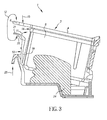
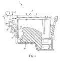
- FIGs. 3 and 4 illustrate a fluid-providing system 1, according to an embodiment of the present invention.
- FIGs. 3 and 4 illustrate the insertion of the multi-chambered fluid reservoir 3 into the chassis 24, according to an embodiment of the present invention.
- the pinching force 12 may be applied to the protruding grip 6 and the lever 10 to carry the fluid reservoir 3 to the position shown in FIG. 3 .
- the lever 10 need not be depressed, and a downward pressing force 15 may be applied to the protruding grip 6 to push the fluid reservoir 3 into the chassis 24.
- the fluid reservoir 3 engages into the chassis 24 as shown in FIG. 4 .
- FIG. 4 represents the fluid reservoir 3 inserted into the chassis 24, and not all of the forces or sounds are applicable at the same time.
- the pinching force 12 is applied, but when the fluid reservoir 3 engages in the chassis 24 as shown in FIG. 4 , the pinching force 12 is typically released and the pressing force 15 is applied.
- FIG. 4 shows pinching force 12 is that this is the force required when removing fluid reservoir 3 from chassis 24. At this time, there is no pressing force 15 applied and a less loud sound results as the latch is disengaged.
- the lever 10 is made of a material and has a configuration that produces an audible click sound 22
- the chassis 24 is made of a relatively stiff plastic that is injection moldable, such as glass-filled polyphenylene oxide. Fluid reservoir 3 and its attached lever 10 are preferably injection molded from a single plastic material such as polypropylene.
- the pinching force 12 is applied to the protruding grip 6 and the pinching-force-application surface 20 of the lever 10 to compress the lever 10 towards the fluid containing body 14, thereby releasing the latch 13 from the chassis 24. Such release allows the fluid reservoir 3 to be removed from the chassis 24.
Landscapes
- Ink Jet (AREA)
Abstract
Embodiments of a printing device fluid reservoir with gripping features are disclosed. In an embodiment of the present invention, the fluid reservoir includes a first surface and a fluid-containing body located beneath the first surface. According to an embodiment of the present invention, the first surface includes a protruding grip, and the fluid-containing body has a lever extending therefrom. According to an embodiment of the present invention, both the protruding grip and the lever are configured to receive a pinching force that compresses the lever towards the fluid-containing body, facilitates carrying of the fluid reservoir, and facilitates installing and/or releasing the fluid reservoir into/from a chassis of the printing device.
Description
- This invention pertains to a printing device fluid reservoir with gripping features. In particular, this invention pertains to gripping features for a fluid reservoir that facilitate holding, insertion of, and removal of the fluid reservoir from a chassis.
- Fluid-ejection printing devices, such as ink jet printers, commonly have at least one fluid reservoir and a chassis that supports the fluid reservoir. The combination of the fluid reservoir and the chassis is referred to herein as a "fluid-providing system." The fluid reservoir may contain one or more fluid chambers that provide fluid to a printhead. If the fluid reservoir has more than one ink chamber, each such chamber often retains fluid of a different color for multi-color printing. On the other hand, if the fluid reservoir has only a single ink chamber, typically such chamber is used to retain black ink for black-and-white printing.
- The printhead commonly is connected directly or indirectly to the chassis. In order to form an image, the printhead, along with the chassis and the fluid reservoir, typically are moved in a lateral direction across a width of a substrate, such as paper, as fluid is ejected from the printhead. After the printhead forms a row-portion of the image along the width of the substrate, the substrate is advanced in a direction perpendicular to the lateral direction along a length of the substrate, so that the printhead can form a subsequent row-portion of the image. This process of advancing the substrate for each row-portion is repeated until a next substrate is needed or the image is completed.
- When an ink chamber in the fluid reservoir runs out of fluid, a user is charged with the responsibility of removing the empty fluid reservoir from the chassis and replacing it with a full fluid reservoir. Consequently, the task of replacing a fluid reservoir into the chassis must be simple and must consistently achieve a proper engagement of the fluid reservoir into the chassis. Otherwise, improper insertion of the fluid reservoir into the chassis may lead to damage to the printing device due to fluid leaks, may cause poorly formed images due to an improper communication of fluid from the fluid reservoir to the printhead, and may result in user frustration. Furthermore, if it is not easy for a user to insert a fluid reservoir into a chassis, or if proper installation is not apparent to the user, the user may resort to using excessive force when inserting the fluid reservoir into the chassis. In this case, excessive contact between fragile components on the fluid reservoir and/or the chassis may occur, thereby resulting in damage. Accordingly, a need in the art exists for an insertion-solution that allows a user to simply and reliably insert a fluid reservoir into a chassis of a fluid-ejecting printing device.
- The above-described problems are addressed and a technical solution is achieved in the art by a printing device fluid reservoir with gripping features according to embodiments of the present invention. In an embodiment of the present invention, the fluid reservoir includes a first surface and a fluid-containing body located beneath the first surface when the fluid reservoir is in an orientation in which it is configured to operate. According to an embodiment of the present invention, the first surface includes a protruding grip, and the fluid-containing body has a lever extending therefrom. According to an embodiment of the present invention, both the protruding grip and the lever are configured to receive a pinching force that compresses the lever towards the fluid-containing body, facilitates carrying of the fluid reservoir, and facilitates installing and/or releasing the fluid reservoir into/from a chassis of the printing device. An advantage of the protruding grip and lever arrangement, according to embodiments of the present invention, is that it serves multiple purposes of carrying the fluid reservoir, installing it into the chassis, and removing it from the chassis.
- According to an embodiment of the present invention, the protruding grip extends horizontally or substantially horizontally beyond an edge of the fluid containing body. According to another embodiment of the invention, the protruding grip may be flat or substantially flat, which may make the fluid reservoir easier to fit into a printing device. Further in this regard, the protruding grip and the first surface of the fluid reservoir form a single flat or substantially flat surface, which also may make the fluid reservoir easier to fit into a printing device. On the other hand, the protruding grip may be curved (along with or separate from the first surface of the fluid reservoir) to facilitate better interaction with a finger applying a pinching force. Further, the protruding grip may include a textured region to facilitate gripping and interaction with a finger applying the pinching force.
- According to an embodiment of the invention, the lever extending from the fluid-containing body, may be located at least in part beneath the protruding grip when the fluid reservoir is in an orientation in which it is configured to operate. The lever may extend further from the fluid-containing body than the protruding grip does. Alternatively, the lever may extend the same or substantially the same distance from the fluid-containing body or less than the distance from the fluid-containing body than the protruding grip does. According to an embodiment of the present invention, the lever is configured to retain a finger by its shape. For example, the lever may have a pinching-force-reception region that is concave to assist it in facilitating reception of a finger applying the pinching force.
- According to an embodiment of the present invention, the lever and, optionally, the chassis are formed of a material and/or are arranged in a configuration that generates an audible sound when the fluid reservoir is properly inserted into the chassis of the printing device. According to this embodiment, a user receives instant and audible feedback regarding when the fluid reservoir is properly inserted into the chassis. According to embodiments of the present invention, sensing devices may be included with the printing device to monitor and determine whether such an audible click has been produced, in order to determine whether the fluid reservoir has been properly inserted into the supporting chassis.
- In addition to the embodiments described above, further embodiments will become apparent by reference to the drawings and by study of the following detailed description.
- The present invention will be more readily understood from the detailed description of exemplary embodiments presented below considered in conjunction with the attached drawings, of which:
-
FIG. 1 illustrates a single-chamber fluid reservoir with gripping features, according to an embodiment of the present invention; -
FIG. 2 illustrates a multi-chamber fluid reservoir with gripping features, according to an embodiment of the present invention; -
FIG. 3 illustrates a fluid reservoir just prior to proper insertion into a supporting chassis, according to an embodiment of the present invention; and -
FIG. 4 illustrates a fluid reservoir properly inserted into a supporting chassis, according to an embodiment of the present invention. - It is to be understood that the attached drawings are for purposes of illustrating the concepts of the invention and may not be to scale.
- Embodiments of the present invention provide a protruding grip and lever combination configured to receive a pinching force, by which the fluid reservoir may easily be carried, inserted into a supporting chassis, or removed from the supporting chassis. As described herein, additional features, such as a flat or substantially flat protruding grip, a curved protruding grip, texture on the protruding grip, a proper curvature of the pinching-force-application surface of the lever, and an audible click when the lever snaps into an engaged position in the chassis provide additional benefits in their own right and need not be used in combination with the other features described herein.
- Turning now to
FIG. 1 , a single-chamber fluid reservoir 2, according to an embodiment of the present invention, is illustrated.Such fluid reservoir 2 includes a single, internal, fluid chamber (not shown) configured to retain fluid. In the case of ink-jet printing, the fluid chamber (not shown) may be used to retain black ink for black-and-white printing. - Also according to the embodiment of
FIG. 1 , thefluid reservoir 2 has a first ortop surface 4 from which agrip 6 protrudes (also referred to as a "protruding grip"). Theprotruding grip 6, according to the embodiment ofFIG. 1 , extends horizontally or substantially horizontally beyond anedge 14 of the fluid-containingbody 8. Although the embodiment ofFIG. 1 illustrates thefirst surface 4 and theprotruding grip 6 as forming a single flat surface, one skilled in the art will appreciate that such a configuration is not required. For instance, theprotruding grip 6 may be curved in a shape that facilitates interaction with a finger applying apinching force 12. However, a flat or substantially flatfirst surface 4 and protrudinggrip 6 may be beneficial in certain implementations and may improve the ease in which thefluid reservoir 2 fits inside a printing device (not shown). - According to the embodiment of
FIG. 1 , thefluid reservoir 2 includes a fluid-containingbody 8 that is located beneath thefirst surface 4 when thefluid reservoir 2 is oriented in a configuration in which thefluid reservoir 2 is designed to operate. In the embodiment ofFIG. 1 , thefluid reservoir 2 is configured to be oriented in ahorizontal direction 7 while operating, i.e., such that thetop surface 4 is substantially aligned along ahorizontal direction 7. Also according to the embodiment ofFIG. 1 , alever 10 extends from asurface 18 of the fluid-containingbody 8 at a point of attachment 9. The combination of theprotruding grip 6 and thelever 10 are configured to receive thepinching force 12 to facilitate carrying thefluid reservoir 2, inserting thefluid reservoir 2 into a chassis 24 (shown inFIGs. 3 and4 ), and removing thefluid reservoir 2 from thechassis 24. In this regard, although not required, a pinching-force-application portion 21 of thelever 10 may be curved concavely so that it approaches being parallel or substantially parallel to protrudinggrip 6, in order to facilitate receiving a finger applying thepinching force 12. As a result, although a portion oflever 10 is perpendicular or substantially perpendicular totop surface 4, a region of pinching-force-application portion 21 is parallel or substantially parallel totop surface 4. In addition, pinching-force-application surface 20 ofportion 21 may be textured or otherwise provided with a friction-inducing surface, such as, for example, a tacky surface or elastomeric surface, for more reliable gripping. Further in this regard, although not required, theprotruding grip 6 may haveregion 16 thereon, such thatregion 16 may facilitate interaction with a finger applying thepinching force 12 thereon. Likesurface 20,region 16 may be textured or otherwise provided with a friction-inducing surface for more reliable gripping. Alternatively, or in combination with a textured surface,region 16 may be located in a depression in protrudinggrip 6. Herein the term finger is used generically and may refer to either a finger or a thumb. Typically the thumb would be applied to protrudinggrip 6 and the index finger would be applied to pinching-force-application surface 20, but other gripping arrangements are possible, so the word finger is used here as well as in the claims. - According to the embodiment of
FIG. 1 , the combination of the protrudinggrip 6 and thelever 10 are configured to receive a pinchingforce 12 in a direction perpendicular or substantially perpendicular to the protrudinggrip 6 and the pinching-force-application surface 20. Further, the combination of the protrudinggrip 6 and thesurface 20 oflever 10 may be configured to receive a pinchingforce 12 in a direction parallel or substantially parallel to aninitial direction 25 in which thefluid reservoir 2 is removed from a chassis 24 (seeFIGs. 3 and4 ). An advantage of this arrangement is that it allows a user to apply the pinchingforce 12 and then lift thefluid reservoir 2 in theinitial direction 25 to remove it from thechassis 24 while the protrudinggrip 6 and thelever 10 support the lifting motion. - Upon application of the pinching
force 12, the lever moves in adirection 11 towardssurface 18 of the fluid-containingbody 8. Such movement, when thefluid reservoir 2 is installed into thechassis 24, releases alatch 13, thereby disengaging thefluid reservoir 2 from the chassis. Upon insertion of thefluid reservoir 2 into thechassis 24, adownward pressure 15 applied to the protrudinggrip 6 causes thelever 10, and itslatch 13 to snap into an engaged position in thechassis 24, (illustrated in detail below). Typically downwardpressure 15 is applied after pinchingforce 12 is released. Such engagement causes an audible sound, such as a click sound, described in more detail below. When carrying thefluid reservoir 2 in an orientation withsurface 4 at the top, according to an embodiment of the present invention, an upward force is applied toportion 21 oflever 10. In order to facilitate carryingfluid reservoir 2 without it slipping out of the hand, the region ofportion 21 oflever 10 that is substantially parallel or substantially parallel to protrudinggrip 6 preferably is designed to extend a minimum of 4 mm in a direction that is perpendicular or substantially perpendicular to surface 18. In addition, whenlever 10 is not pinched,portion 21 is designed to extend a minimum distance of 10 mm fromsurface 18, including the gap betweenlever 10 andsurface 18. - Turning now to
FIG. 2 , amulti-chambered fluid reservoir 3, according to an embodiment of the present invention, is illustrated. The embodiment ofFIG. 2 uses the same reference numerals to indicate same or similar features. According to the embodiment ofFIG. 2 , themulti-chambered fluid reservoir 3 includes the same or similar features as the single-chamberedfluid reservoir 2 inFIG. 1 , except that themulti-chambered fluid reservoir 3 is wider and includes multiple separate chambers (not shown), each for retaining its own supply of fluid. For example, if thefluid reservoir 3 were a multi-chambered ink tank used with an ink jet printer, each chamber (not shown) may be used to retain cyan, magenta, yellow, and black inks, respectively, for multi-color printing. - According to both embodiments of
FIG. 1 andFIG. 2 , thetop surface 4 and protrudinggrip 6 may consist of a lid or cover which is affixed to fluid containingbody 8. In such a case, thelid body 8 by welding or adhesive prior to fillingbody 8 with fluid. -
FIGs. 3 and4 illustrate a fluid-providing system 1, according to an embodiment of the present invention. When viewed in sequence,FIGs. 3 and4 illustrate the insertion of themulti-chambered fluid reservoir 3 into thechassis 24, according to an embodiment of the present invention. In this sequence, the pinchingforce 12 may be applied to the protrudinggrip 6 and thelever 10 to carry thefluid reservoir 3 to the position shown inFIG. 3 . Thereafter, thelever 10 need not be depressed, and a downward pressingforce 15 may be applied to the protrudinggrip 6 to push thefluid reservoir 3 into thechassis 24. After application of thepressing force 15, thefluid reservoir 3 engages into thechassis 24 as shown inFIG. 4 . Such engagement causes an audible sound, such as aclick sound 22, when thelatch 13 is engaged with thechassis 24. It should be noted thatFIG. 4 represents thefluid reservoir 3 inserted into thechassis 24, and not all of the forces or sounds are applicable at the same time. Whenfluid reservoir 3 is being inserted as inFIG. 3 , the pinchingforce 12 is applied, but when thefluid reservoir 3 engages in thechassis 24 as shown inFIG. 4 , the pinchingforce 12 is typically released and thepressing force 15 is applied. The reasonFIG. 4 shows pinching force 12 is that this is the force required when removingfluid reservoir 3 fromchassis 24. At this time, there is no pressingforce 15 applied and a less loud sound results as the latch is disengaged. According to embodiments of the present invention, thelever 10 is made of a material and has a configuration that produces anaudible click sound 22 According to an embodiment of the present invention thechassis 24 is made of a relatively stiff plastic that is injection moldable, such as glass-filled polyphenylene oxide.Fluid reservoir 3 and its attachedlever 10 are preferably injection molded from a single plastic material such as polypropylene. - In order to remove the
fluid reservoir 3 from thechassis 24, according to an embodiment of the present invention, the pinchingforce 12 is applied to the protrudinggrip 6 and the pinching-force-application surface 20 of thelever 10 to compress thelever 10 towards thefluid containing body 14, thereby releasing thelatch 13 from thechassis 24. Such release allows thefluid reservoir 3 to be removed from thechassis 24. -
- 1. A fluid reservoir configured to provide image-forming fluid for a printing device, the fluid reservoir comprising:
- a first surface comprising a protruding grip; and
- a fluid-containing body located beneath the first surface when the fluid reservoir is in an orientation in which the fluid reservoir is configured to operate, the fluid-containing body comprising a lever extending therefrom,
- wherein both the protruding grip and a portion of the lever are configured to receive a pinching force applied in a direction perpendicular or substantially perpendicular to the protruding grip.
- 2. The fluid reservoir of item 1, wherein the lever is configured to move towards the fluid-containing body when the pinching force is applied thereto.
- 3. The fluid reservoir of
item 2, wherein a portion of the lever is configured to be gripped when the pinching force is applied and the fluid reservoir is carried. - 4. The fluid reservoir of item 1, further comprising a plurality of fluid chambers each configured to retain its own supply of fluid.
- 5. The fluid reservoir of item 1, wherein the protruding grip extends beyond an edge of the fluid-containing body, the edge of the fluid-containing body being an edge of a surface of the fluid-containing body to which the lever is attached.
- 6. The fluid reservoir of item 5, wherein the lever extends further from the fluid-containing body than the protruding grip extends from the fluid-containing body.
- 7. The fluid reservoir of item 5, wherein the lever extends a same or substantially a same amount of distance from the fluid-containing body as does the protruding grip.
- 8. The fluid reservoir of item 1, wherein a region of pinching-force-application portion is parallel or substantially parallel to the first surface.
- 9. The fluid reservoir of item 1, further comprising a surface that includes the lever, wherein a region of the pinching-force-application surface is parallel or substantially parallel to the first surface, and wherein the region extends at least 4 mm in a direction perpendicular or substantially perpendicular to the surface to which the lever is attached.
- 10. The fluid reservoir of item 1, further comprising a surface that includes the lever, wherein a region of the pinching-force-application surface is parallel or substantially parallel to the first surface, and wherein the region extends to a distance which is at least 10 mm from the surface to which the lever is attached.
- 11. The fluid reservoir of item 1, wherein the lever extends from a surface of the fluid-containing body, and wherein the protruding grip extends in a direction perpendicular or substantially perpendicular to a direction in which the surface extends.
- 12. The fluid reservoir of item 1, wherein the protruding grip and the lever are configured, when inserted into a chassis, to produce an audible sound when the fluid reservoir is properly inserted into the chassis.
- 13. A fluid-providing system configured to provide image-forming fluid for a printing device, the fluid-providing system comprising:
- a fluid reservoir comprising (a) a first surface comprising a protruding grip, and (b) a fluid-containing body located beneath the first surface when the fluid reservoir is in an orientation in which the fluid reservoir is configured to operate, the fluid-containing body comprising a lever extending therefrom, wherein both the protruding grip and the lever are configured to receive a pinching force; and
- a chassis configured to retain the fluid reservoir in the printing device,
- wherein the lever and the chassis are configured to interact to produce an audible noise when the fluid reservoir is inserted into the chassis, and
- wherein the protruding grip and the lever are configured to facilitate removing the fluid reservoir from the chassis when the pinching force is applied to the protruding grip and the lever.
- 14. A fluid reservoir configured to provide image-forming fluid for a printing device, the fluid reservoir comprising:
- a first surface comprising a protruding grip; and
- a fluid-containing body located beneath the first surface when the fluid reservoir is in an orientation in which the fluid reservoir is configured to operate, the fluid-containing body comprising a lever extending therefrom,
- wherein the lever, at least in part, is located beneath the protruding grip when the fluid reservoir is in an orientation in which the fluid reservoir is configured to operate,
- wherein both the protruding grip and the lever are configured to receive a pinching force, and
- wherein the lever is configured to move towards the fluid-containing body when the pinching force is applied thereto.
- 15. The fluid reservoir of
item 14, wherein the lever, in its entirety, is located beneath the protruding grip when the fluid reservoir is in an orientation in which the fluid reservoir is configured to operate. - 16. A fluid reservoir configured to provide image-forming fluid for a printing device, the fluid reservoir comprising:
- a first surface comprising a protruding grip; and
- a fluid-containing body located beneath the first surface when the fluid reservoir is in an orientation in which the fluid reservoir is configured to operate, the fluid-containing body comprising a lever extending therefrom,
- wherein both the protruding grip and the lever are configured to receive a pinching force,
- wherein the lever is configured to move towards the fluid-containing body when the pinching force is applied thereto, and
- wherein the protruding grip extends substantially horizontally beyond an edge of the fluid-containing body when the fluid reservoir is in an orientation in which the fluid reservoir is configured to operate.
- 17. A fluid reservoir configured to provide image-forming fluid for a printing device, the fluid reservoir comprising:
- a first surface comprising a protruding grip, the first surface and the protruding grip forming a single flat or substantially flat surface; and
- a fluid-containing body located beneath the first surface when the fluid reservoir is in an orientation in which the fluid reservoir is configured to operate, the fluid-containing body comprising a lever extending therefrom,
- wherein both the protruding grip and the lever are configured to receive a pinching force, and
- wherein the lever is configured to move towards the fluid-containing body when the pinching force is applied thereto.
- 18. A fluid reservoir configured to provide image-forming fluid for a printing device, the fluid reservoir comprising:
- a fluid-containing body comprising a lever extending therefrom; and
- a lid affixed to the fluid containing body, the lid comprising a protruding grip,
wherein the lever is configured to move towards the fluid-containing body when the pinching force is applied thereto. - 19. The fluid reservoir of
item 18, wherein the lever comprises a pinching-force-application portion configured to receive the pinching force, and wherein a region of the pinching-force-application portion is concave. - 20. The fluid reservoir of
item 18, wherein a portion of the lever is perpendicular or substantially perpendicular to the lid, and wherein a portion of the lever is parallel or substantially parallel to the lid. -
- 1
- Fluid-providing system
- 2
- Fluid reservoir
- 3
- Multi-chamber fluid reservoir
- 4
- First surface
- 6
- Protruding grip
- 8
- Fluid-containing body
- 9
- Attachment point
- 10
- Lever
- 11
- Direction
- 12
- Pinching force
- 13
- Latch
- 14
- Edge
- 15
- Downward Pressure
- 16
- Texture
- 18
- Surface of a fluid-containing body
- 20
- Surface
- 21
- Portion of lever
- 22
- Click
- 24
- Chassis
- 25
- Direction
Claims (4)
- A fluid reservoir configured to provide image-forming fluid for a printing device, the fluid reservoir comprising:a first surface, a second surface and at least one third surface extending between the first surface and the second surface;a fluid-containing body located beneath the first surface when the fluid reservoir is in an orientation in which the fluid reservoir is configured to operate; anda compressible lever extending from the third surface in a direction from the second surface to the first surface; wherein, when the fluid reservoir is removed, the lever is compressed to move towards the fluid-containing body.
- The fluid reservoir of claim 1, wherein the lever is compressed to move towards the fluid-containing body when the fluid reservoir is inserted into a chassis.
- The fluid reservoir of claim 1, wherein the lever is configured, when inserted into a chassis, to produce an audible sound when the fluid reservoir is properly inserted into the chassis.
- The fluid reservoir of claim 1, wherein a first portion of the lever is substantially perpendicular to the first surface.
Applications Claiming Priority (2)
| Application Number | Priority Date | Filing Date | Title |
|---|---|---|---|
| US11/614,147 US7690774B2 (en) | 2006-12-21 | 2006-12-21 | Printing device fluid reservoir with gripping features |
| EP07862613.2A EP2094493B1 (en) | 2006-12-21 | 2007-12-06 | Printing device fluid reservoir with gripping features |
Related Parent Applications (1)
| Application Number | Title | Priority Date | Filing Date |
|---|---|---|---|
| EP07862613.2 Division | 2007-12-06 |
Publications (1)
| Publication Number | Publication Date |
|---|---|
| EP2433804A1 true EP2433804A1 (en) | 2012-03-28 |
Family
ID=39154120
Family Applications (3)
| Application Number | Title | Priority Date | Filing Date |
|---|---|---|---|
| EP11195094A Withdrawn EP2433804A1 (en) | 2006-12-21 | 2007-12-06 | Printing device fluid reservoir with gripping features |
| EP11195093A Withdrawn EP2433803A1 (en) | 2006-12-21 | 2007-12-06 | Printing device fluid reservoir with gripping features |
| EP07862613.2A Not-in-force EP2094493B1 (en) | 2006-12-21 | 2007-12-06 | Printing device fluid reservoir with gripping features |
Family Applications After (2)
| Application Number | Title | Priority Date | Filing Date |
|---|---|---|---|
| EP11195093A Withdrawn EP2433803A1 (en) | 2006-12-21 | 2007-12-06 | Printing device fluid reservoir with gripping features |
| EP07862613.2A Not-in-force EP2094493B1 (en) | 2006-12-21 | 2007-12-06 | Printing device fluid reservoir with gripping features |
Country Status (6)
| Country | Link |
|---|---|
| US (3) | US7690774B2 (en) |
| EP (3) | EP2433804A1 (en) |
| JP (3) | JP2010513094A (en) |
| CN (1) | CN101600576B (en) |
| TW (3) | TW201202051A (en) |
| WO (1) | WO2008076227A1 (en) |
Families Citing this family (12)
| Publication number | Priority date | Publication date | Assignee | Title |
|---|---|---|---|---|
| US7690774B2 (en) * | 2006-12-21 | 2010-04-06 | Eastman Kodak Company | Printing device fluid reservoir with gripping features |
| US7810917B2 (en) * | 2006-12-21 | 2010-10-12 | Eastman Kodak Company | Printing device fluid reservoir with alignment features |
| US8246141B2 (en) * | 2006-12-21 | 2012-08-21 | Eastman Kodak Company | Insert molded printhead substrate |
| US7976138B2 (en) * | 2006-12-21 | 2011-07-12 | Eastman Kodak Company | Data-providing-component securing mechanism for printing apparatus reservoir |
| FR2957727B1 (en) | 2010-03-22 | 2012-03-09 | Legrand France | RAIL SUPPORT FOR MOUNTING ELECTRICAL EQUIPMENT IN AN ELECTRICAL BOX |
| US8469490B2 (en) | 2011-10-26 | 2013-06-25 | Eastman Kodak Company | Ink tank configuration for inkjet printer |
| WO2013062860A1 (en) | 2011-10-26 | 2013-05-02 | Eastman Kodak Company | Ink distribution configuration for carriage inkjet printer |
| JP6079362B2 (en) * | 2013-03-27 | 2017-02-15 | ブラザー工業株式会社 | Printing fluid supply apparatus and printing fluid cartridge |
| JP6202052B2 (en) * | 2014-08-29 | 2017-09-27 | セイコーエプソン株式会社 | Liquid supply unit |
| JP6753054B2 (en) * | 2015-11-27 | 2020-09-09 | セイコーエプソン株式会社 | Liquid storage container and protective member |
| USD934341S1 (en) | 2018-12-03 | 2021-10-26 | Hewlett-Packard Development Company, L.P. | Ink cartridge |
| JP7322465B2 (en) * | 2019-03-29 | 2023-08-08 | ブラザー工業株式会社 | image forming device |
Citations (5)
| Publication number | Priority date | Publication date | Assignee | Title |
|---|---|---|---|---|
| WO2001054911A1 (en) * | 2000-01-31 | 2001-08-02 | Hewlett-Packard Company | Latch and handle arrangement for a replaceable ink container |
| US20030035035A1 (en) * | 1999-10-06 | 2003-02-20 | Komplin Steven Robert | Replaceable ink cartridge for ink jet pen |
| US6623104B1 (en) * | 1999-10-04 | 2003-09-23 | Canon Kabushiki Kaisha | Liquid container, cap used with the liquid container, and cap-equipped liquid container |
| US20040135857A1 (en) * | 2002-11-26 | 2004-07-15 | Kazuhiro Hashii | Ink cartridge and recording apparatus |
| EP1512536A1 (en) * | 2002-06-11 | 2005-03-09 | Seiko Epson Corporation | Ink cartridge |
Family Cites Families (9)
| Publication number | Priority date | Publication date | Assignee | Title |
|---|---|---|---|---|
| US5646654A (en) | 1995-03-09 | 1997-07-08 | Hewlett-Packard Company | Ink-jet printing system having acoustic transducer for determining optimum operating energy |
| US6454400B1 (en) | 1998-09-01 | 2002-09-24 | Canon Kabushiki Kaisha | Liquid container, cartridge including liquid container, printing apparatus using cartridge and liquid discharge printing apparatus |
| JP3706776B2 (en) | 1998-09-03 | 2005-10-19 | キヤノン株式会社 | Ink tank, tank holder, inkjet head cartridge, and inkjet recording apparatus |
| US6390601B1 (en) | 1998-10-27 | 2002-05-21 | Canon Kabushiki Kaisha | Ink tank, ink jet head cartridge, and ink jet recording apparatus |
| JP2001353878A (en) * | 2000-06-13 | 2001-12-25 | Canon Inc | Liquid storage container for discharge and liquid discharge recording device |
| JP2002079674A (en) * | 2000-09-04 | 2002-03-19 | Canon Inc | Liquid discharge head unit, head cartridge and method of manufacturing liquid discharge head unit |
| JP2004122487A (en) | 2002-09-30 | 2004-04-22 | Canon Inc | Liquid tank and tank holder, head cartridge, recording device, tank attaching / detaching method |
| ATE381992T1 (en) | 2002-11-26 | 2008-01-15 | Seiko Epson Corp | INK CARTRIDGE |
| US7690774B2 (en) * | 2006-12-21 | 2010-04-06 | Eastman Kodak Company | Printing device fluid reservoir with gripping features |
-
2006
- 2006-12-21 US US11/614,147 patent/US7690774B2/en not_active Expired - Fee Related
-
2007
- 2007-12-06 EP EP11195094A patent/EP2433804A1/en not_active Withdrawn
- 2007-12-06 WO PCT/US2007/025028 patent/WO2008076227A1/en not_active Ceased
- 2007-12-06 EP EP11195093A patent/EP2433803A1/en not_active Withdrawn
- 2007-12-06 EP EP07862613.2A patent/EP2094493B1/en not_active Not-in-force
- 2007-12-06 JP JP2009542793A patent/JP2010513094A/en active Pending
- 2007-12-06 CN CN2007800472852A patent/CN101600576B/en not_active Expired - Fee Related
- 2007-12-20 TW TW100128254A patent/TW201202051A/en unknown
- 2007-12-20 TW TW096149076A patent/TW200836933A/en unknown
- 2007-12-20 TW TW100128256A patent/TW201206715A/en unknown
-
2010
- 2010-02-15 US US12/705,687 patent/US8057028B2/en not_active Expired - Fee Related
- 2010-02-15 US US12/705,673 patent/US8061829B2/en not_active Expired - Fee Related
-
2011
- 2011-09-13 JP JP2011199727A patent/JP2012011784A/en not_active Withdrawn
- 2011-09-13 JP JP2011199726A patent/JP2012056314A/en not_active Withdrawn
Patent Citations (5)
| Publication number | Priority date | Publication date | Assignee | Title |
|---|---|---|---|---|
| US6623104B1 (en) * | 1999-10-04 | 2003-09-23 | Canon Kabushiki Kaisha | Liquid container, cap used with the liquid container, and cap-equipped liquid container |
| US20030035035A1 (en) * | 1999-10-06 | 2003-02-20 | Komplin Steven Robert | Replaceable ink cartridge for ink jet pen |
| WO2001054911A1 (en) * | 2000-01-31 | 2001-08-02 | Hewlett-Packard Company | Latch and handle arrangement for a replaceable ink container |
| EP1512536A1 (en) * | 2002-06-11 | 2005-03-09 | Seiko Epson Corporation | Ink cartridge |
| US20040135857A1 (en) * | 2002-11-26 | 2004-07-15 | Kazuhiro Hashii | Ink cartridge and recording apparatus |
Also Published As
| Publication number | Publication date |
|---|---|
| TW201206715A (en) | 2012-02-16 |
| JP2012056314A (en) | 2012-03-22 |
| EP2094493B1 (en) | 2013-04-17 |
| EP2433803A1 (en) | 2012-03-28 |
| US8061829B2 (en) | 2011-11-22 |
| WO2008076227A1 (en) | 2008-06-26 |
| JP2012011784A (en) | 2012-01-19 |
| US20080151016A1 (en) | 2008-06-26 |
| TW201202051A (en) | 2012-01-16 |
| US20100141718A1 (en) | 2010-06-10 |
| CN101600576A (en) | 2009-12-09 |
| JP2010513094A (en) | 2010-04-30 |
| EP2094493A1 (en) | 2009-09-02 |
| TW200836933A (en) | 2008-09-16 |
| US7690774B2 (en) | 2010-04-06 |
| US8057028B2 (en) | 2011-11-15 |
| US20100141717A1 (en) | 2010-06-10 |
| CN101600576B (en) | 2011-09-14 |
Similar Documents
| Publication | Publication Date | Title |
|---|---|---|
| EP2094493B1 (en) | Printing device fluid reservoir with gripping features | |
| JP4133154B2 (en) | Ink cartridge and inkjet printer | |
| US7967426B2 (en) | Sealing device for fluid reservoir | |
| EP3247562B1 (en) | Liquid consuming apparatus | |
| JP6693076B2 (en) | tank | |
| CN107878035B (en) | Liquid cartridge and liquid consuming apparatus | |
| JP6969162B2 (en) | Waste liquid container and liquid injection device | |
| JP4304225B2 (en) | Ink cartridge and inkjet printer | |
| JP6734063B2 (en) | ink cartridge | |
| JP6079362B2 (en) | Printing fluid supply apparatus and printing fluid cartridge | |
| CN201721131U (en) | Ink box on ink jet printer | |
| JP2002337358A (en) | ink cartridge | |
| CN212353315U (en) | Electrical contact protection member and ink jet printer having the same | |
| JP2016168802A (en) | Image forming apparatus | |
| JP6428289B2 (en) | Liquid consumption device | |
| KR100406976B1 (en) | Cartridge mounting apparatus for ink-jet printer | |
| US20250042169A1 (en) | Ink container | |
| TW561110B (en) | Ink cartridge and method of production thereof | |
| JP4001000B2 (en) | Inkjet recording device | |
| CN116890540A (en) | Liquid storage containers and liquid ejection devices | |
| JP2003053997A (en) | Ink jet recording device and ink tank | |
| JP2001054950A (en) | Ink container |
Legal Events
| Date | Code | Title | Description |
|---|---|---|---|
| PUAI | Public reference made under article 153(3) epc to a published international application that has entered the european phase |
Free format text: ORIGINAL CODE: 0009012 |
|
| AC | Divisional application: reference to earlier application |
Ref document number: 2094493 Country of ref document: EP Kind code of ref document: P |
|
| AK | Designated contracting states |
Kind code of ref document: A1 Designated state(s): AT BE BG CH CY CZ DE DK EE ES FI FR GB GR HU IE IS IT LI LT LU LV MC MT NL PL PT RO SE SI SK TR |
|
| STAA | Information on the status of an ep patent application or granted ep patent |
Free format text: STATUS: THE APPLICATION IS DEEMED TO BE WITHDRAWN |
|
| 18D | Application deemed to be withdrawn |
Effective date: 20120929 |