EP2433545A1 - Handy mop - Google Patents
Handy mop Download PDFInfo
- Publication number
- EP2433545A1 EP2433545A1 EP10777826A EP10777826A EP2433545A1 EP 2433545 A1 EP2433545 A1 EP 2433545A1 EP 10777826 A EP10777826 A EP 10777826A EP 10777826 A EP10777826 A EP 10777826A EP 2433545 A1 EP2433545 A1 EP 2433545A1
- Authority
- EP
- European Patent Office
- Prior art keywords
- insert
- grip
- mounting part
- mop
- space
- Prior art date
- Legal status (The legal status is an assumption and is not a legal conclusion. Google has not performed a legal analysis and makes no representation as to the accuracy of the status listed.)
- Granted
Links
Images
Classifications
-
- A—HUMAN NECESSITIES
- A47—FURNITURE; DOMESTIC ARTICLES OR APPLIANCES; COFFEE MILLS; SPICE MILLS; SUCTION CLEANERS IN GENERAL
- A47L—DOMESTIC WASHING OR CLEANING; SUCTION CLEANERS IN GENERAL
- A47L13/00—Implements for cleaning floors, carpets, furniture, walls, or wall coverings
- A47L13/10—Scrubbing; Scouring; Cleaning; Polishing
- A47L13/38—Other dusting implements
-
- A—HUMAN NECESSITIES
- A47—FURNITURE; DOMESTIC ARTICLES OR APPLIANCES; COFFEE MILLS; SPICE MILLS; SUCTION CLEANERS IN GENERAL
- A47L—DOMESTIC WASHING OR CLEANING; SUCTION CLEANERS IN GENERAL
- A47L13/00—Implements for cleaning floors, carpets, furniture, walls, or wall coverings
- A47L13/10—Scrubbing; Scouring; Cleaning; Polishing
- A47L13/42—Details
- A47L13/46—Securing scouring or polishing cloths or sponges to the handles by gripping means, tongs, or the like
-
- B—PERFORMING OPERATIONS; TRANSPORTING
- B25—HAND TOOLS; PORTABLE POWER-DRIVEN TOOLS; MANIPULATORS
- B25G—HANDLES FOR HAND IMPLEMENTS
- B25G3/00—Attaching handles to the implements
- B25G3/02—Socket, tang, or like fixings
- B25G3/12—Locking and securing devices
- B25G3/18—Locking and securing devices comprising catches or pawls
Definitions
- the invention relates to a hand-held mop which has a mop body and a grip and is used for cleaning inside or outside of a room or a vehicle, and more particularly to a hand-held mop in which the grip is prevented from becoming detached from a mounting part for mounting the mop body during cleaning operation.
- Japanese non-examined laid-open Patent Publication No. 2007-167425 discloses a hand-held mop with a disposable mop body, a mounting part connected to the mop body to support the mop body and a grip connected to the mounting part.
- the known hand-held mop is used for a fine cleaning operation by inserting it into a relatively complicated and narrow structure inside a room or a vehicle
- the mounting part In order to insert the hand-held mop into a relatively complicated and narrow structure and smoothly perform a cleaning operation by lightly pressing the mop body against an object to be cleaned, the mounting part needs to bend when pressed by the user. Therefore, the mounting part for supporting the mop body must be made of a relatively soft material.
- the grip connected to the mounting part needs to be securely held by the user, so that it is made of a relatively hard synthetic resin such as PP (polypropylene).
- the soft mounting part and the hard grip are connected to each other, however, the soft mounting part and the hard grip may easily become disconnected from each other at the connection, which will interfere with the cleaning operation.
- the invention provides a hand-held mop including a mop body, a mounting part and a grip.
- the mop body includes a mop body portion having a mounting space.
- the mounting part has a mounting piece which is inserted into the mounting space of the mop body portion, and an insert.
- the grip has a holding side which defines an insert space into which the insert of the mounting part is inserted, and the grip has a higher hardness than the mounting part. Further, a side opening is formed in the holding side of the grip, and a side projection is formed on the insert of the mounting part and engaged in the side opening of the grip.
- a spring region is formed in the holding side of the grip, and when the insert is inserted into the insert space, the spring region is pressed by the side projection of the insert and bent.
- the spring region is provided as an example of an elastic region to exert biasing force. For example, a leaf spring member can be utilized.
- the mounting part and the grip are long and narrow, and the side opening formed in the holding side of the grip extends in a width direction of the grip, so that the spring region is formed between the side opening and a front end of the holding side in the holding side.
- the width of the insert of the mounting part is shorter than the width of the insert space of the grip, and when the spring region is pressed by the side projection of the insert, the spring region can freely bend in its width direction without interference of the insert.
- a contact projection is formed on a side of a front end of the insert of the mounting part and comes in contact with an inner wall of the insert space of the grip.
- a proximal end projection is formed on a proximal end of the insert of the mounting part, and a positioning opening is formed in the insert space of the grip and receives the proximal end projection.
- the grip is made of polypropylene (PP).
- the spring region of the grip has a shorter extent in its longitudinal direction than in its width direction.
- an engagement protruding piece is formed on each of the mounting pieces of the mounting part and extends outward and is engaged in the mounting space of the mop body portion.
- a soft grip is prevented from becoming detached from a hard mounting part for mounting and supporting a mop body.
- FIGS. 1 to 6 show a hand-held mop according to the embodiment of the invention.
- a hand-held mop 1 includes a mop body 2, an elongate mounting part 10 and an elongate grip 20.
- the mop body 2 includes a pair of mop body portions 2a each having a mounting space 3.
- the mounting part 10 is made of a soft synthetic resin material such as elastomer.
- the mounting part 10 includes a pair of mounting pieces 11 which are formed on its front end side and inserted into the mounting spaces 3 of the mop body portions 2a, and an insert 15 formed on its proximal end.
- the grip 20 is made of a harder synthetic resin material than the material of the mounting part 10, such as PP (polypropylene), and includes a holding side 22 and a grip body 21.
- the holding side 22 is formed on the front end of the grip 20 and defines an insert space 22a into which the insert 15 of the mounting part 10 is inserted.
- the mounting part 10 is made of a soft material which can bend when pressed by the user.
- the grip 20 needs to be securely held by the user, so that it is made of a hard material.
- the mop body 1 includes the pair of mop body portions 2a as described above, and each of the mop body portions 2a is formed by bonding nonwoven fabric sheets 4 together.
- the mounting space 3 is formed between the bonded nonwoven fabric sheets 4.
- each of the mop body portions 2a has a mop part 5 formed on the front and back sides of the nonwoven fabric sheets 4 and formed of fine nonwoven fabric having a cleaning function. Cleaning is performed by the mop part 5.
- the nonwoven fabric sheets 4 of the mop body portions 2a are bonded together on the proximal end of the mop body portions 2a.
- the nonwoven fabric sheets 4 are not bonded on the front end side of the mop body portions 2a and a cleaning space 7 is formed between the mop body portions 2a.
- the mop parts 5 of the mop body portions 2a are used to clean a structure inside a room or a vehicle. Further, by inserting the structure into the cleaning space 7, the structure can be reliably cleaned even if it is small.
- the mounting part 10 includes the pair of mounting pieces 11 which are inserted into the mounting spaces 3 of the mop body portions 2a, and the insert 15 connected to the mounting pieces 11.
- the mounting pieces 11 are situated on the front end side of the mounting part 10, and the insert 15 is situated on the proximal end side.
- the mounting part 10 is formed of soft elastomer as a whole so that the mounting part 10 can hold the mop body 2 and deform the mop body 2 such that the mop body 2 conforms to the contour of the structure to be cleaned.
- the mounting pieces 11 of the mounting part 10 have flexibility so that the mop body 2 can deform in such a manner as to conform to the contour of the structure.
- the soft elastomer forming the mounting part 10 olefinic thermoplastic elastomer is used. Specifically, Zelas (registered trademark) of Mitsubishi Chemical Co., Ltd. can be used as the olefinic thermoplastic elastomer.
- a semicircular plate-like engagement protruding piece 12 is formed on each of the mounting pieces 11 and protrudes outward so that it engages with the mounting space 3 of the mop body portion 2a.
- the insert 15 formed on the proximal end of the mounting part 10 is inserted into an insert space 22a of the grip 20, so that the mounting part 10 is securely connected to the grip 20, which will be described below.
- a guide piece 16 is formed on one side of the insert 15 of the mounting part 10 and serves to guide the insert 15 in sliding contact with a side edge 25a of a cover 25 of the grip 20 when the insert 15 is inserted into the insert space 22a of the grip 20.
- the top of the guide piece 16 is substantially flush with the top of the mounting pieces.
- the insert space 22a is formed on the front end of the grip 20 and the insert 15 of the mounting part 10 is inserted into the insert space 22a as described above.
- the insert space 22a is defined by a holding side 22 for holding the insert 15 and a pair of bent covers 25 formed on the both side edges of the holding side 22 ( FIG. 6 (a)(b) ).
- a side opening 23 is formed in the holding side 22 of the grip 20, and a side projection 19 is formed on the insert 15 of the mounting part 10 and engages with the side opening 23 of the grip 20.
- the side opening 23 formed in the holding side 22 of the grip 20 extends along a width direction L 2 of the grip 20, and a spring region 24 is formed between the side opening 23 and a front end 22b of the holding side 22 in the holding side 22.
- the grip 20 is a part to be held by a user when the user uses the hand-held mop 1 and formed of a harder material (polypropylene) than the mounting part 10.
- a harder material polypropylene
- the spring region 24 of the holding side 22 has an extent 1 1 extending from the side opening 23 to the front end 22b in a longitudinal direction L 1 and has an extent 1 2 in the width direction L 2 corresponding to the width of the side opening 23.
- the extent 1 1 of the spring region 24 in the longitudinal direction L 1 is shorter than the extent 1 2 in the width direction L 2 such that the spring region 24 can reliably bend along the width direction L 2 .
- a width L 3 of the insert 15 of the mounting part 10 is shorter than a width L 4 of the insert space 22a of the grip 20 ( FIGS. 3 , 6(a) and 6(b) ).
- the side projection 19 of the insert 15 comes in contact with the inner wall of the spring region 24.
- the insert 15 does not interfere with bending of the spring region 24 because the width L 3 of the insert 15 is shorter than the width L 4 of the insert space 22a.
- the side projection 19 of the insert 15 comes in contact with the inner wall of the spring region 24 and the spring region 24 bends along the width direction L 2 , the protruding height of the side projection 19 of the insert 15 can be increased to the greatest extent practicable (for example, 0.1 to 1.0 mm higher than a conventional product). Therefore, the side projection 19 of the insert 15 can be securely engaged in the side opening 23 of the grip 20.
- a pair of contact projections 17 are formed on the both sides of the front end of the insert 15 of the mounting part 10 and come in contact with the inner wall of the insert space 22a of the grip 20.
- the width L 3 of the insert 15 of the mounting part 10 is shorter than the width L 4 of the insert space 22a of the grip 20, so that a clearance is created between the insert 15 of the mounting part 10 and the insert space 22a of the grip 20 when the insert 15 is inserted into the insert space 22a.
- the contact projections 17 come in contact with the inner wall of the insert space 22a of the grip 20. Therefore, the insert 15 can be securely mounted into the insert space 22a, so that the mounting part 10 and the grip 20 can be securely connected to each other.
- a proximal end projection 18 is formed on the proximal end of the insert 15 of the mounting part 10, and a positioning opening 26 is formed in the insert space 22a of the grip 20 and receives the proximal end projection 18 and particularly serves to position it in the width direction L 2 .
- the mounting part 10 and the grip 20 are connected to each other.
- the insert 15 of the mounting part 10 is inserted into the insert space 22a of the grip 20.
- the side projection 19 of the insert 15 which protrudes to the greatest extent practicable comes in contact with the inner wall of the spring region 24 on the holding side 22 of the grip 20.
- the spring region 24, having the extent 1 2 in the width direction L 2 which is longer than the extent 1 1 in the longitudinal direction L 1 can smoothly bend along the width direction L 2 when the side projection 19 of the insert 15 comes in contact with the inner wall of the spring region 24.
- the insert 15, having the width L 3 shorter than the width L 4 of the insert space 22a does not interfere with bending of the spring region 24.
- the relatively large side opening 23 is formed in the holding side 22 of the grip 20 and extends along the width direction L 2 of the grip 20, and the side opening 23 defines the spring region 24 between the side opening 23 and the front end 22b of the holding side 22 in the holding side 22.
- the side opening 23 largely extends along the width direction L 2 . so that the spring region 24 has the extent 1 2 in the width direction L 2 which is longer than the extent 1 1 in the longitudinal direction L 1 . Therefore, the spring region 24 can easily deform in the width direction L 2 .
- the width L 3 of the insert 15 is shorter than the width L 4 of the insert space 22a. Therefore, when inserting the insert 15 of the mounting part 10 into the insert space 22a of the grip 20, first, the side projection 19 (protruding to a greater extent than a conventional product) of the insert 15 comes into contact with the spring region 24 of the holding side 22 and presses it. At this time, the spring region 24 bends along the width direction L 2 , so that the width L 4 of the insert space 22a is shortened. Even if the spring region 24 bends, however, the insert 15 does not interfere with bending of the spring region 24 because the width L 3 of the insert 15 is shorter than the width L 4 of the insert space 22a. With such a construction that the width L 3 of the insert 15 is shorter than the width L 4 of the insert space 22a and the insert 15 does not interfere with bending of the spring region 24, the insert 15 can be smoothly inserted into the insert space 22a.
- the contact projections 17 of the insert 15 come in contact with the inner wall of the insert space 22a. Therefore, the insert 15 can be reliably mounted into the insert space 22a, so that the mounting part 10 and the grip 20 can be securely connected to each other.
- the proximal end projection 18 of the insert 15 is inserted into the positioning opening 26 of the insert space 22a and positions the insert 15 in the width direction L 2 .
- the side projection 19 of the insert 15 When the insert 15 of the mounting part 10 is completely inserted into the insert space 22a of the grip 20, the side projection 19 of the insert 15 is engaged in the side opening 23 of the grip 20. In this case, the side projection 19 of the insert 15 does not easily become detached from the side opening 23 because the side projection 19 protrudes to a greater extent than a conventional product. Further, as described above, by provision of the contact projections 17 of the insert 15 which come in contact with the inner wall of the insert space 22a, the insert 15 does not rattle within the insert space 22a along the width direction L 2 . Further, the proximal end projection 18 of the insert 15 is inserted into the positioning opening 26 of the insert space 22a, so that the insert 15 can be properly positioned in the width direction L 2 within the insert space 22a as described above.
- the mounting pieces 11 of the mounting part 10 are inserted into the associated mounting spaces 3 formed in the mop body portions 2a, 2b of the mop body 2, so that the mop body 2 is connected to the mounting part 10. In this manner, the hand-held mop 1 can be obtained.
- the grip body 21 of the grip 20 is held by the user and a cleaning operation is performed on a structure inside a room or a vehicle with the mop body 2 held in contact with the structure.
- Each of the mop body portions 2a of the mop body 2 has the mop part 5 formed on its front and back sides, so that the structure to be cleaned can be easily and reliably cleaned.
- the structure can be reliably cleaned by inserting it into the cleaning space 7 of the mop body 2.
- the side projection 19 of the insert 15 can be configured to protrude from the insert 15 to a greater extent, for example, 0.1 to 1.0 mm higher than a conventional product. Therefore, even if a great force is applied from the grip 20 to the mounting part 10 during cleaning operation using the hand-held mop 1, the side projection 19 of the insert 15 does not become detached from the side opening 23 of the holding side 22. Thus, the insert 15 of the mounting part 10 can be reliably mounted into the insert space 22a of the grip 20, so that the hard grip 20 does not become detached from the soft mounting part 10.
- the side projection 19 of the insert 15 comes in contact with the inner wall of the spring region 24 of the grip 20.
- the spring region 24 bends along the width direction L 2 , so that the insert 15 can be smoothly inserted into the insert space 22a.
- the side projection 19 can be engaged in the side opening 23, so that the insert 15 can be securely held within the insert space 22a. Therefore, even if the user holds the grip 20 and applies a great force from the grip 20 to the mounting part 10 during cleaning operation using the hand-held mop 1, the hard grip 20 does not become detached from the soft mounting part 10.
- the mop body 2 is described as having a pair of the mop body portions 2a, but it may have only one mop body portion 2a.
- a pair of the contact projections 17 are described as being formed on the both sides of the insert 15, but a contact projection 17 which comes in contact with the inner wall of the insert space 22a may be formed only on one side of the insert 15.
Landscapes
- Engineering & Computer Science (AREA)
- Mechanical Engineering (AREA)
- Cleaning Implements For Floors, Carpets, Furniture, Walls, And The Like (AREA)
Abstract
Description
- The invention relates to a hand-held mop which has a mop body and a grip and is used for cleaning inside or outside of a room or a vehicle, and more particularly to a hand-held mop in which the grip is prevented from becoming detached from a mounting part for mounting the mop body during cleaning operation.
- Japanese non-examined laid-open Patent Publication No.
2007-167425 - In order to insert the hand-held mop into a relatively complicated and narrow structure and smoothly perform a cleaning operation by lightly pressing the mop body against an object to be cleaned, the mounting part needs to bend when pressed by the user. Therefore, the mounting part for supporting the mop body must be made of a relatively soft material.
- On the other hand, the grip connected to the mounting part needs to be securely held by the user, so that it is made of a relatively hard synthetic resin such as PP (polypropylene).
- In a construction in which the soft mounting part and the hard grip are connected to each other, however, the soft mounting part and the hard grip may easily become disconnected from each other at the connection, which will interfere with the cleaning operation.
- Accordingly, it is an object of the invention to provide a hand-held mop in which a hard grip connected to a soft mounting part for mounting the mop body is prevented from becoming detached from the mounting part, during cleaning operation.
- The invention provides a hand-held mop including a mop body, a mounting part and a grip. The mop body includes a mop body portion having a mounting space. The mounting part has a mounting piece which is inserted into the mounting space of the mop body portion, and an insert. The grip has a holding side which defines an insert space into which the insert of the mounting part is inserted, and the grip has a higher hardness than the mounting part. Further, a side opening is formed in the holding side of the grip, and a side projection is formed on the insert of the mounting part and engaged in the side opening of the grip. A spring region is formed in the holding side of the grip, and when the insert is inserted into the insert space, the spring region is pressed by the side projection of the insert and bent. The spring region is provided as an example of an elastic region to exert biasing force. For example, a leaf spring member can be utilized.
- In the hand-held mop according to the invention, the mounting part and the grip are long and narrow, and the side opening formed in the holding side of the grip extends in a width direction of the grip, so that the spring region is formed between the side opening and a front end of the holding side in the holding side.
- As one aspect of the invention, the width of the insert of the mounting part is shorter than the width of the insert space of the grip, and when the spring region is pressed by the side projection of the insert, the spring region can freely bend in its width direction without interference of the insert. Further, a contact projection is formed on a side of a front end of the insert of the mounting part and comes in contact with an inner wall of the insert space of the grip.
- As one aspect of the invention, a proximal end projection is formed on a proximal end of the insert of the mounting part, and a positioning opening is formed in the insert space of the grip and receives the proximal end projection.
- As one aspect of the invention, the grip is made of polypropylene (PP).
- As one aspect of the invention, the spring region of the grip has a shorter extent in its longitudinal direction than in its width direction.
- As one aspect of the invention, an engagement protruding piece is formed on each of the mounting pieces of the mounting part and extends outward and is engaged in the mounting space of the mop body portion.
- As described above, according to the invention, during cleaning operation using a hand-held mop, a soft grip is prevented from becoming detached from a hard mounting part for mounting and supporting a mop body.
- Other objects, features and advantages of the invention will be readily understood after reading the following detailed description together with the accompanying drawings and the claims.
-
-
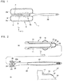
FIG. 1 is a plan view showing an entire hand-held mop according to the invention. -
FIG. 2(a) is an exploded plan view of a mounting part and a grip, andFIG. 2(b) is an enlarged view of a proximal end of the mounting part. -
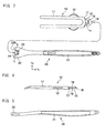
FIG. 3 is an exploded back view of the mounting part and the grip. -
FIG. 4 is a side view of the mounting part. -
FIG. 5 is a side view of the grip. -
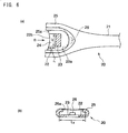
FIG. 6(a) is an enlarged view of a front end portion of the grip, andFIG. 6(b) is a view taken from a direction of arrow B inFIG. 6(a) . - Each of the additional features and method steps disclosed above and below may be utilized separately or in conjunction with other features and method steps to provide and manufacture improved hand-held mops and method for using such hand-held mops and devices utilized therein. Representative examples of the invention, which examples utilized many of these additional features and method steps in conjunction, will now be described in detail with reference to the drawings. This detailed description is merely intended to teach a person skilled in the art further details for practicing preferred aspects of the present teachings and is not intended to limit the scope of the invention. Only the claims define the scope of the claimed invention. Therefore, combinations of features and steps disclosed within the following detailed description may not be necessary to practice the invention in the broadest sense, and are instead taught merely to particularly describe some representative examples of the invention, which detailed description will now be given with reference to the accompanying drawings.
-
FIGS. 1 to 6 show a hand-held mop according to the embodiment of the invention. - As shown in
FIGS. 1, 2(a) and 2(b) , a hand-heldmop 1 includes amop body 2, an elongate mountingpart 10 and anelongate grip 20. Themop body 2 includes a pair ofmop body portions 2a each having a mountingspace 3. The mountingpart 10 is made of a soft synthetic resin material such as elastomer. The mountingpart 10 includes a pair of mountingpieces 11 which are formed on its front end side and inserted into the mountingspaces 3 of themop body portions 2a, and aninsert 15 formed on its proximal end. Thegrip 20 is made of a harder synthetic resin material than the material of the mountingpart 10, such as PP (polypropylene), and includes a holdingside 22 and agrip body 21. The holdingside 22 is formed on the front end of thegrip 20 and defines aninsert space 22a into which theinsert 15 of the mountingpart 10 is inserted. - In this case, in order to realize a smooth cleaning operation by lightly pressing the
mop body 10 against an object to be cleaned, the mountingpart 10 is made of a soft material which can bend when pressed by the user. - On the other hand, the
grip 20 needs to be securely held by the user, so that it is made of a hard material. - The
mop body 1 includes the pair ofmop body portions 2a as described above, and each of themop body portions 2a is formed by bondingnonwoven fabric sheets 4 together. The mountingspace 3 is formed between the bondednonwoven fabric sheets 4. - Further, each of the
mop body portions 2a has amop part 5 formed on the front and back sides of thenonwoven fabric sheets 4 and formed of fine nonwoven fabric having a cleaning function. Cleaning is performed by themop part 5. - The
nonwoven fabric sheets 4 of themop body portions 2a are bonded together on the proximal end of themop body portions 2a. Thenonwoven fabric sheets 4 are not bonded on the front end side of themop body portions 2a and acleaning space 7 is formed between themop body portions 2a. Themop parts 5 of themop body portions 2a are used to clean a structure inside a room or a vehicle. Further, by inserting the structure into the cleaningspace 7, the structure can be reliably cleaned even if it is small. - As shown in
FIGS. 1,2(a), 2(b) ,3,4,5 ,6(a) and 6(b) , the mountingpart 10 includes the pair of mountingpieces 11 which are inserted into the mountingspaces 3 of themop body portions 2a, and theinsert 15 connected to the mountingpieces 11. The mountingpieces 11 are situated on the front end side of the mountingpart 10, and theinsert 15 is situated on the proximal end side. The mountingpart 10 is formed of soft elastomer as a whole so that the mountingpart 10 can hold themop body 2 and deform themop body 2 such that themop body 2 conforms to the contour of the structure to be cleaned. Particularly, the mountingpieces 11 of the mountingpart 10 have flexibility so that themop body 2 can deform in such a manner as to conform to the contour of the structure. As the soft elastomer forming the mountingpart 10, olefinic thermoplastic elastomer is used. Specifically, Zelas (registered trademark) of Mitsubishi Chemical Co., Ltd. can be used as the olefinic thermoplastic elastomer. - A semicircular plate-like
engagement protruding piece 12 is formed on each of themounting pieces 11 and protrudes outward so that it engages with themounting space 3 of themop body portion 2a. - The
insert 15 formed on the proximal end of the mountingpart 10 is inserted into aninsert space 22a of thegrip 20, so that the mountingpart 10 is securely connected to thegrip 20, which will be described below. Aguide piece 16 is formed on one side of theinsert 15 of the mountingpart 10 and serves to guide theinsert 15 in sliding contact with aside edge 25a of acover 25 of thegrip 20 when theinsert 15 is inserted into theinsert space 22a of thegrip 20. The top of theguide piece 16 is substantially flush with the top of the mounting pieces. - The
insert space 22a is formed on the front end of thegrip 20 and theinsert 15 of the mountingpart 10 is inserted into theinsert space 22a as described above. Theinsert space 22a is defined by a holdingside 22 for holding theinsert 15 and a pair of bent covers 25 formed on the both side edges of the holding side 22 (FIG. 6 (a)(b) ). - As shown in
FIG. 3 , aside opening 23 is formed in the holdingside 22 of thegrip 20, and aside projection 19 is formed on theinsert 15 of the mountingpart 10 and engages with theside opening 23 of thegrip 20. In this case, theside opening 23 formed in the holdingside 22 of thegrip 20 extends along a width direction L2 of thegrip 20, and aspring region 24 is formed between theside opening 23 and afront end 22b of the holdingside 22 in the holdingside 22. - The
grip 20 is a part to be held by a user when the user uses the hand-heldmop 1 and formed of a harder material (polypropylene) than the mountingpart 10. By provision of thespring region 24 between theside opening 23 and thefront end 22b in the holdingside 22, when theinsert 15 of the mountingpart 10 is inserted into theinsert space 22a of thegrip 20, theside projection 19 of theinsert 15 comes in contact with an inner wall of thespring region 24 so that thespring region 24 can bend along the width direction L2 of thegrip 20. - In this case, the
spring region 24 of the holdingside 22 has anextent 11 extending from theside opening 23 to thefront end 22b in a longitudinal direction L1 and has anextent 12 in the width direction L2 corresponding to the width of theside opening 23. Theextent 11 of thespring region 24 in the longitudinal direction L1 is shorter than theextent 12 in the width direction L2 such that thespring region 24 can reliably bend along the width direction L2. - Further, a width L3 of the
insert 15 of the mountingpart 10 is shorter than a width L4 of theinsert space 22a of the grip 20 (FIGS. 3 ,6(a) and 6(b) ). When theinsert 15 of the mountingpart 10 is inserted into theinsert space 22a of thegrip 20, theside projection 19 of theinsert 15 comes in contact with the inner wall of thespring region 24. At this time, when thespring region 24 bends along the width direction L2, theinsert 15 does not interfere with bending of thespring region 24 because the width L3 of theinsert 15 is shorter than the width L4 of theinsert space 22a. - With such a construction that, when the
insert 15 of the mountingpart 10 is inserted into theinsert space 22a of thegrip 20, theside projection 19 of theinsert 15 comes in contact with the inner wall of thespring region 24 and thespring region 24 bends along the width direction L2, the protruding height of theside projection 19 of theinsert 15 can be increased to the greatest extent practicable (for example, 0.1 to 1.0 mm higher than a conventional product). Therefore, theside projection 19 of theinsert 15 can be securely engaged in theside opening 23 of thegrip 20. - Further, as shown in
FIGS. 2(a) and 2(b) , a pair ofcontact projections 17 are formed on the both sides of the front end of theinsert 15 of the mountingpart 10 and come in contact with the inner wall of theinsert space 22a of thegrip 20. Specifically, as described above, the width L3 of theinsert 15 of the mountingpart 10 is shorter than the width L4 of theinsert space 22a of thegrip 20, so that a clearance is created between theinsert 15 of the mountingpart 10 and theinsert space 22a of thegrip 20 when theinsert 15 is inserted into theinsert space 22a. However, when theinsert 15 is completely inserted into theinsert space 22a, thecontact projections 17 come in contact with the inner wall of theinsert space 22a of thegrip 20. Therefore, theinsert 15 can be securely mounted into theinsert space 22a, so that the mountingpart 10 and thegrip 20 can be securely connected to each other. - Further, a
proximal end projection 18 is formed on the proximal end of theinsert 15 of the mountingpart 10, and apositioning opening 26 is formed in theinsert space 22a of thegrip 20 and receives theproximal end projection 18 and particularly serves to position it in the width direction L2. - Operation of this embodiment having the above-described construction is now explained.
- First, the mounting
part 10 and thegrip 20 are connected to each other. In this case, theinsert 15 of the mountingpart 10 is inserted into theinsert space 22a of thegrip 20. At this time, theside projection 19 of theinsert 15 which protrudes to the greatest extent practicable comes in contact with the inner wall of thespring region 24 on the holdingside 22 of thegrip 20. Thespring region 24, having theextent 12 in the width direction L2 which is longer than theextent 11 in the longitudinal direction L1, can smoothly bend along the width direction L2 when theside projection 19 of theinsert 15 comes in contact with the inner wall of thespring region 24. Further, theinsert 15, having the width L3 shorter than the width L4 of theinsert space 22a, does not interfere with bending of thespring region 24. - Connection between the mounting
part 10 and thegrip 20 is now further explained. The relativelylarge side opening 23 is formed in the holdingside 22 of thegrip 20 and extends along the width direction L2 of thegrip 20, and theside opening 23 defines thespring region 24 between theside opening 23 and thefront end 22b of the holdingside 22 in the holdingside 22. In this case, theside opening 23 largely extends along the width direction L2. so that thespring region 24 has theextent 12 in the width direction L2 which is longer than theextent 11 in the longitudinal direction L1. Therefore, thespring region 24 can easily deform in the width direction L2. - Further, as described above, the width L3 of the
insert 15 is shorter than the width L4 of theinsert space 22a. Therefore, when inserting theinsert 15 of the mountingpart 10 into theinsert space 22a of thegrip 20, first, the side projection 19 (protruding to a greater extent than a conventional product) of theinsert 15 comes into contact with thespring region 24 of the holdingside 22 and presses it. At this time, thespring region 24 bends along the width direction L2, so that the width L4 of theinsert space 22a is shortened. Even if thespring region 24 bends, however, theinsert 15 does not interfere with bending of thespring region 24 because the width L3 of theinsert 15 is shorter than the width L4 of theinsert space 22a. With such a construction that the width L3 of theinsert 15 is shorter than the width L4 of theinsert space 22a and theinsert 15 does not interfere with bending of thespring region 24, theinsert 15 can be smoothly inserted into theinsert space 22a. - When the
insert 15 of the mountingpart 10 is completely inserted into theinsert space 22a of thegrip 20, thecontact projections 17 of theinsert 15 come in contact with the inner wall of theinsert space 22a. Therefore, theinsert 15 can be reliably mounted into theinsert space 22a, so that the mountingpart 10 and thegrip 20 can be securely connected to each other. At the same time, theproximal end projection 18 of theinsert 15 is inserted into thepositioning opening 26 of theinsert space 22a and positions theinsert 15 in the width direction L2. - When the
insert 15 of the mountingpart 10 is completely inserted into theinsert space 22a of thegrip 20, theside projection 19 of theinsert 15 is engaged in theside opening 23 of thegrip 20. In this case, theside projection 19 of theinsert 15 does not easily become detached from theside opening 23 because theside projection 19 protrudes to a greater extent than a conventional product. Further, as described above, by provision of thecontact projections 17 of theinsert 15 which come in contact with the inner wall of theinsert space 22a, theinsert 15 does not rattle within theinsert space 22a along the width direction L2. Further, theproximal end projection 18 of theinsert 15 is inserted into thepositioning opening 26 of theinsert space 22a, so that theinsert 15 can be properly positioned in the width direction L2 within theinsert space 22a as described above. - Next, the mounting
pieces 11 of the mountingpart 10 are inserted into the associated mountingspaces 3 formed in themop body portions 2a, 2b of themop body 2, so that themop body 2 is connected to the mountingpart 10. In this manner, the hand-heldmop 1 can be obtained. - In use of the hand-held
mop 1, thegrip body 21 of thegrip 20 is held by the user and a cleaning operation is performed on a structure inside a room or a vehicle with themop body 2 held in contact with the structure. - Each of the
mop body portions 2a of themop body 2 has themop part 5 formed on its front and back sides, so that the structure to be cleaned can be easily and reliably cleaned. - In the case of a narrow or thin structure, the structure can be reliably cleaned by inserting it into the cleaning
space 7 of themop body 2. - As described above, the
side projection 19 of theinsert 15 can be configured to protrude from theinsert 15 to a greater extent, for example, 0.1 to 1.0 mm higher than a conventional product. Therefore, even if a great force is applied from thegrip 20 to the mountingpart 10 during cleaning operation using the hand-heldmop 1, theside projection 19 of theinsert 15 does not become detached from theside opening 23 of the holdingside 22. Thus, theinsert 15 of the mountingpart 10 can be reliably mounted into theinsert space 22a of thegrip 20, so that thehard grip 20 does not become detached from the soft mountingpart 10. - As described above, according to this embodiment, when the
insert 15 is inserted into theinsert space 22a in order to connect thegrip 20 to the mountingpart 10, theside projection 19 of theinsert 15 comes in contact with the inner wall of thespring region 24 of thegrip 20. In this case, thespring region 24 bends along the width direction L2, so that theinsert 15 can be smoothly inserted into theinsert space 22a. At the same time, theside projection 19 can be engaged in theside opening 23, so that theinsert 15 can be securely held within theinsert space 22a. Therefore, even if the user holds thegrip 20 and applies a great force from thegrip 20 to the mountingpart 10 during cleaning operation using the hand-heldmop 1, thehard grip 20 does not become detached from the soft mountingpart 10. - Further, in the above-described embodiment, the
mop body 2 is described as having a pair of themop body portions 2a, but it may have only onemop body portion 2a. - Further, a pair of the
contact projections 17 are described as being formed on the both sides of theinsert 15, but acontact projection 17 which comes in contact with the inner wall of theinsert space 22a may be formed only on one side of theinsert 15. -
- 1 hand-held mop
- 2 mop body
- 2a, 2b mop body portion
- 3 mounting space
- 10 mounting part
- 11 mounting piece
- 12 engagement protruding piece
- 15 insert
- 16 guide piece
- 17 contact projection
- 18 proximal end projection
- 19 side projection
- 20 grip
- 21 grip body
- 22 holding side
- 22a insert space
- 23 side opening
- 24 spring region
- 25 cover
- 26 positioning opening
Claims (7)
- A hand-held mop comprising:a mop body including a mop body portion having a mounting space,a mounting part having an mounting piece and an insert, the mounting piece being inserted into the mounting space of the mop body portion anda grip having a holding side which defines an insert space into which the insert of the mounting part is inserted, the grip having a higher hardness than the mounting part, wherein:a side opening is formed in the holding side of the grip,a side projection is formed on the insert of the mounting part and engaged in the side opening of the grip, anda spring region is formed in the holding side of the grip, and when the insert is inserted into the insert space, the spring region is pressed by the side projection of the insert and bent.
- The hand-held mop as defined in claim 1, wherein the mounting part and the grip are long and narrow, and the side opening formed in the holding side of the grip extends in a width direction of the grip so that the spring region is formed between the side opening and a front end of the holding side in the holding side.
- The hand-held mop as defined in claim 2, wherein the width of the insert of the mounting part is shorter than the width of the insert space of the grip, and when the spring region is pressed by the side projection of the insert, the spring region can freely bend in its width direction without interference of the insert, and wherein a contact projection is formed on a side of a front end of the insert of the mounting part and comes in contact with an inner wall of the insert space of the grip.
- The hand-held mop as defined in any one of claims 1 to 3, wherein a proximal end projection is formed on a proximal end of the insert of the mounting part, and a positioning opening is formed in the insert space of the grip and receives the proximal end projection.
- The hand-held mop as defined in any one of claims 1 to 4, wherein the grip is made of polypropylene.
- The hand-held mop as defined in any one of claims 1 to 5, wherein the spring region of the grip has a shorter extent in its longitudinal direction than in its width direction.
- The hand-held mop as defined in any one of claims 1 to 6, wherein an engagement protruding piece is formed on each of the mounting pieces of the mounting part and extends outward and is engaged in the mounting space of the mop body portion.
Applications Claiming Priority (2)
| Application Number | Priority Date | Filing Date | Title |
|---|---|---|---|
| JP2009123489A JP5405194B2 (en) | 2009-05-21 | 2009-05-21 | Handy mop |
| PCT/JP2010/058621 WO2010134594A1 (en) | 2009-05-21 | 2010-05-21 | Handy mop |
Publications (3)
| Publication Number | Publication Date |
|---|---|
| EP2433545A1 true EP2433545A1 (en) | 2012-03-28 |
| EP2433545A4 EP2433545A4 (en) | 2012-12-19 |
| EP2433545B1 EP2433545B1 (en) | 2016-02-10 |
Family
ID=43126271
Family Applications (1)
| Application Number | Title | Priority Date | Filing Date |
|---|---|---|---|
| EP10777826.8A Active EP2433545B1 (en) | 2009-05-21 | 2010-05-21 | Handy mop |
Country Status (6)
| Country | Link |
|---|---|
| US (1) | US20120124763A1 (en) |
| EP (1) | EP2433545B1 (en) |
| JP (1) | JP5405194B2 (en) |
| CN (1) | CN102438498A (en) |
| TW (1) | TW201102037A (en) |
| WO (1) | WO2010134594A1 (en) |
Families Citing this family (5)
| Publication number | Priority date | Publication date | Assignee | Title |
|---|---|---|---|---|
| US20130052381A1 (en) * | 2011-08-22 | 2013-02-28 | Robert R. Gallucci | Polyepoxides and epoxy resins and methods for the manufacture and use thereof |
| JP6470036B2 (en) * | 2014-12-25 | 2019-02-13 | 花王株式会社 | Cleaning tool |
| US10688649B1 (en) * | 2017-02-14 | 2020-06-23 | Martinez Tool Company, Inc. | Implement handle grip having an improved handle engaging mechanism |
| KR102123527B1 (en) * | 2019-04-04 | 2020-06-17 | (주)광진상사 | Cleaning tool |
| KR102148684B1 (en) * | 2019-04-04 | 2020-08-27 | 황성철 | Cleaning tool |
Family Cites Families (12)
| Publication number | Priority date | Publication date | Assignee | Title |
|---|---|---|---|---|
| JPH1086660A (en) * | 1996-09-13 | 1998-04-07 | Fuji Heavy Ind Ltd | Positioning clip of window glass for vehicle |
| JP3044362U (en) * | 1997-06-13 | 1997-12-22 | 株式会社イモタニ | Handy mop |
| JP4050035B2 (en) * | 2000-10-27 | 2008-02-20 | ユニ・チャーム株式会社 | Handy mop |
| JP4132730B2 (en) * | 2001-06-14 | 2008-08-13 | ユニ・チャーム株式会社 | Cleaning products |
| TWI239538B (en) * | 2004-03-25 | 2005-09-11 | Darfon Electronics Corp | Transformer and lamp driving system using the same |
| US20070174987A1 (en) * | 2004-03-29 | 2007-08-02 | Yamada Chiyoe | Cleaning device and holding member used for the same |
| JP4688455B2 (en) * | 2004-09-09 | 2011-05-25 | ユニ・チャーム株式会社 | Cleaning tool |
| JP2007044088A (en) * | 2005-08-05 | 2007-02-22 | Azuma Industrial Co Ltd | Handy mop |
| ES2388746T3 (en) * | 2005-10-19 | 2012-10-18 | Kao Corporation | Cleaning tool |
| JP2007167425A (en) * | 2005-12-22 | 2007-07-05 | Kao Corp | Cleaning tool |
| JP4709105B2 (en) * | 2006-09-12 | 2011-06-22 | ユニ・チャーム株式会社 | Cleaning body and cleaning tool |
| JP5235493B2 (en) * | 2008-05-15 | 2013-07-10 | ユニ・チャーム株式会社 | Cleaning tool, cleaning body holder |
-
2009
- 2009-05-21 JP JP2009123489A patent/JP5405194B2/en not_active Expired - Fee Related
-
2010
- 2010-05-20 TW TW099116149A patent/TW201102037A/en unknown
- 2010-05-21 WO PCT/JP2010/058621 patent/WO2010134594A1/en not_active Ceased
- 2010-05-21 CN CN2010800221945A patent/CN102438498A/en active Pending
- 2010-05-21 EP EP10777826.8A patent/EP2433545B1/en active Active
- 2010-05-21 US US13/321,543 patent/US20120124763A1/en not_active Abandoned
Also Published As
| Publication number | Publication date |
|---|---|
| EP2433545A4 (en) | 2012-12-19 |
| WO2010134594A1 (en) | 2010-11-25 |
| JP2010268973A (en) | 2010-12-02 |
| US20120124763A1 (en) | 2012-05-24 |
| EP2433545B1 (en) | 2016-02-10 |
| CN102438498A (en) | 2012-05-02 |
| JP5405194B2 (en) | 2014-02-05 |
| TW201102037A (en) | 2011-01-16 |
Similar Documents
| Publication | Publication Date | Title |
|---|---|---|
| EP2433545B1 (en) | Handy mop | |
| US8931407B2 (en) | Stamp assembly | |
| KR102052925B1 (en) | Cover of cup holder device for vehicle | |
| JP6002327B2 (en) | Reinforcing leaf spring for plastic clips | |
| JP2003166511A (en) | Joint structure | |
| JP5724829B2 (en) | Brush support for painting | |
| US8678512B2 (en) | High chair | |
| JP5411567B2 (en) | Cleaning tool | |
| WO2022024635A1 (en) | Seat | |
| CN111051099B (en) | mirror unit | |
| JPH0135392Y2 (en) | ||
| JP4449002B2 (en) | Shutter curtain deflection control structure | |
| KR200472328Y1 (en) | Holder for holding a shelf to a rail | |
| JP4430471B2 (en) | Parts mounting structure | |
| JP4616797B2 (en) | Water bottle with handle | |
| JP7265924B2 (en) | cleaning tool | |
| JP2010089453A (en) | Clip for writing utensil | |
| JP4419196B2 (en) | Assembly structure in instrumentation | |
| JP2005214332A (en) | Fitting structure of additional member | |
| CN101340038A (en) | Card board structure of electric connector | |
| CN201112939Y (en) | Card board structure of electric connector | |
| JP3166601U (en) | Handy mop fitting | |
| JP4562181B2 (en) | Sponge sandwich | |
| JP3787997B2 (en) | Side knock type writing instrument | |
| CN118418195A (en) | Kitchen knife auxiliary handle and kitchen knife device |
Legal Events
| Date | Code | Title | Description |
|---|---|---|---|
| PUAI | Public reference made under article 153(3) epc to a published international application that has entered the european phase |
Free format text: ORIGINAL CODE: 0009012 |
|
| 17P | Request for examination filed |
Effective date: 20111215 |
|
| AK | Designated contracting states |
Kind code of ref document: A1 Designated state(s): AL AT BE BG CH CY CZ DE DK EE ES FI FR GB GR HR HU IE IS IT LI LT LU LV MC MK MT NL NO PL PT RO SE SI SK SM TR |
|
| AX | Request for extension of the european patent |
Extension state: BA ME RS |
|
| RIN1 | Information on inventor provided before grant (corrected) |
Inventor name: SUDA, TOMOKAZU Inventor name: FUKUZAWA MASUMI Inventor name: TANAKA YOSHINORI Inventor name: UENISHI, TOSHIHIKO Inventor name: URAGAMI, JUN |
|
| A4 | Supplementary search report drawn up and despatched |
Effective date: 20121119 |
|
| RIC1 | Information provided on ipc code assigned before grant |
Ipc: A47L 13/20 20060101AFI20121113BHEP Ipc: A47L 13/10 20060101ALI20121113BHEP |
|
| GRAP | Despatch of communication of intention to grant a patent |
Free format text: ORIGINAL CODE: EPIDOSNIGR1 |
|
| INTG | Intention to grant announced |
Effective date: 20150805 |
|
| GRAS | Grant fee paid |
Free format text: ORIGINAL CODE: EPIDOSNIGR3 |
|
| GRAA | (expected) grant |
Free format text: ORIGINAL CODE: 0009210 |
|
| AK | Designated contracting states |
Kind code of ref document: B1 Designated state(s): AL AT BE BG CH CY CZ DE DK EE ES FI FR GB GR HR HU IE IS IT LI LT LU LV MC MK MT NL NO PL PT RO SE SI SK SM TR |
|
| AX | Request for extension of the european patent |
Extension state: BA ME RS |
|
| REG | Reference to a national code |
Ref country code: GB Ref legal event code: FG4D |
|
| REG | Reference to a national code |
Ref country code: AT Ref legal event code: REF Ref document number: 774236 Country of ref document: AT Kind code of ref document: T Effective date: 20160215 Ref country code: CH Ref legal event code: EP |
|
| REG | Reference to a national code |
Ref country code: IE Ref legal event code: FG4D |
|
| REG | Reference to a national code |
Ref country code: DE Ref legal event code: R096 Ref document number: 602010030577 Country of ref document: DE |
|
| REG | Reference to a national code |
Ref country code: FR Ref legal event code: PLFP Year of fee payment: 7 |
|
| REG | Reference to a national code |
Ref country code: LT Ref legal event code: MG4D |
|
| REG | Reference to a national code |
Ref country code: NL Ref legal event code: MP Effective date: 20160210 |
|
| REG | Reference to a national code |
Ref country code: AT Ref legal event code: MK05 Ref document number: 774236 Country of ref document: AT Kind code of ref document: T Effective date: 20160210 |
|
| PG25 | Lapsed in a contracting state [announced via postgrant information from national office to epo] |
Ref country code: NO Free format text: LAPSE BECAUSE OF FAILURE TO SUBMIT A TRANSLATION OF THE DESCRIPTION OR TO PAY THE FEE WITHIN THE PRESCRIBED TIME-LIMIT Effective date: 20160510 Ref country code: HR Free format text: LAPSE BECAUSE OF FAILURE TO SUBMIT A TRANSLATION OF THE DESCRIPTION OR TO PAY THE FEE WITHIN THE PRESCRIBED TIME-LIMIT Effective date: 20160210 Ref country code: ES Free format text: LAPSE BECAUSE OF FAILURE TO SUBMIT A TRANSLATION OF THE DESCRIPTION OR TO PAY THE FEE WITHIN THE PRESCRIBED TIME-LIMIT Effective date: 20160210 Ref country code: IT Free format text: LAPSE BECAUSE OF FAILURE TO SUBMIT A TRANSLATION OF THE DESCRIPTION OR TO PAY THE FEE WITHIN THE PRESCRIBED TIME-LIMIT Effective date: 20160210 Ref country code: GR Free format text: LAPSE BECAUSE OF FAILURE TO SUBMIT A TRANSLATION OF THE DESCRIPTION OR TO PAY THE FEE WITHIN THE PRESCRIBED TIME-LIMIT Effective date: 20160511 Ref country code: FI Free format text: LAPSE BECAUSE OF FAILURE TO SUBMIT A TRANSLATION OF THE DESCRIPTION OR TO PAY THE FEE WITHIN THE PRESCRIBED TIME-LIMIT Effective date: 20160210 |
|
| PG25 | Lapsed in a contracting state [announced via postgrant information from national office to epo] |
Ref country code: PL Free format text: LAPSE BECAUSE OF FAILURE TO SUBMIT A TRANSLATION OF THE DESCRIPTION OR TO PAY THE FEE WITHIN THE PRESCRIBED TIME-LIMIT Effective date: 20160210 Ref country code: LV Free format text: LAPSE BECAUSE OF FAILURE TO SUBMIT A TRANSLATION OF THE DESCRIPTION OR TO PAY THE FEE WITHIN THE PRESCRIBED TIME-LIMIT Effective date: 20160210 Ref country code: SE Free format text: LAPSE BECAUSE OF FAILURE TO SUBMIT A TRANSLATION OF THE DESCRIPTION OR TO PAY THE FEE WITHIN THE PRESCRIBED TIME-LIMIT Effective date: 20160210 Ref country code: PT Free format text: LAPSE BECAUSE OF FAILURE TO SUBMIT A TRANSLATION OF THE DESCRIPTION OR TO PAY THE FEE WITHIN THE PRESCRIBED TIME-LIMIT Effective date: 20160613 Ref country code: LT Free format text: LAPSE BECAUSE OF FAILURE TO SUBMIT A TRANSLATION OF THE DESCRIPTION OR TO PAY THE FEE WITHIN THE PRESCRIBED TIME-LIMIT Effective date: 20160210 Ref country code: IS Free format text: LAPSE BECAUSE OF FAILURE TO SUBMIT A TRANSLATION OF THE DESCRIPTION OR TO PAY THE FEE WITHIN THE PRESCRIBED TIME-LIMIT Effective date: 20160610 Ref country code: BE Free format text: LAPSE BECAUSE OF NON-PAYMENT OF DUE FEES Effective date: 20160531 Ref country code: AT Free format text: LAPSE BECAUSE OF FAILURE TO SUBMIT A TRANSLATION OF THE DESCRIPTION OR TO PAY THE FEE WITHIN THE PRESCRIBED TIME-LIMIT Effective date: 20160210 Ref country code: NL Free format text: LAPSE BECAUSE OF FAILURE TO SUBMIT A TRANSLATION OF THE DESCRIPTION OR TO PAY THE FEE WITHIN THE PRESCRIBED TIME-LIMIT Effective date: 20160210 |
|
| PG25 | Lapsed in a contracting state [announced via postgrant information from national office to epo] |
Ref country code: EE Free format text: LAPSE BECAUSE OF FAILURE TO SUBMIT A TRANSLATION OF THE DESCRIPTION OR TO PAY THE FEE WITHIN THE PRESCRIBED TIME-LIMIT Effective date: 20160210 Ref country code: DK Free format text: LAPSE BECAUSE OF FAILURE TO SUBMIT A TRANSLATION OF THE DESCRIPTION OR TO PAY THE FEE WITHIN THE PRESCRIBED TIME-LIMIT Effective date: 20160210 |
|
| REG | Reference to a national code |
Ref country code: DE Ref legal event code: R097 Ref document number: 602010030577 Country of ref document: DE |
|
| PG25 | Lapsed in a contracting state [announced via postgrant information from national office to epo] |
Ref country code: CZ Free format text: LAPSE BECAUSE OF FAILURE TO SUBMIT A TRANSLATION OF THE DESCRIPTION OR TO PAY THE FEE WITHIN THE PRESCRIBED TIME-LIMIT Effective date: 20160210 Ref country code: SM Free format text: LAPSE BECAUSE OF FAILURE TO SUBMIT A TRANSLATION OF THE DESCRIPTION OR TO PAY THE FEE WITHIN THE PRESCRIBED TIME-LIMIT Effective date: 20160210 Ref country code: RO Free format text: LAPSE BECAUSE OF FAILURE TO SUBMIT A TRANSLATION OF THE DESCRIPTION OR TO PAY THE FEE WITHIN THE PRESCRIBED TIME-LIMIT Effective date: 20160210 Ref country code: SK Free format text: LAPSE BECAUSE OF FAILURE TO SUBMIT A TRANSLATION OF THE DESCRIPTION OR TO PAY THE FEE WITHIN THE PRESCRIBED TIME-LIMIT Effective date: 20160210 |
|
| PLBE | No opposition filed within time limit |
Free format text: ORIGINAL CODE: 0009261 |
|
| STAA | Information on the status of an ep patent application or granted ep patent |
Free format text: STATUS: NO OPPOSITION FILED WITHIN TIME LIMIT |
|
| PG25 | Lapsed in a contracting state [announced via postgrant information from national office to epo] |
Ref country code: BE Free format text: LAPSE BECAUSE OF FAILURE TO SUBMIT A TRANSLATION OF THE DESCRIPTION OR TO PAY THE FEE WITHIN THE PRESCRIBED TIME-LIMIT Effective date: 20160210 Ref country code: LU Free format text: LAPSE BECAUSE OF FAILURE TO SUBMIT A TRANSLATION OF THE DESCRIPTION OR TO PAY THE FEE WITHIN THE PRESCRIBED TIME-LIMIT Effective date: 20160521 |
|
| REG | Reference to a national code |
Ref country code: CH Ref legal event code: PL |
|
| 26N | No opposition filed |
Effective date: 20161111 |
|
| PG25 | Lapsed in a contracting state [announced via postgrant information from national office to epo] |
Ref country code: LI Free format text: LAPSE BECAUSE OF NON-PAYMENT OF DUE FEES Effective date: 20160531 Ref country code: CH Free format text: LAPSE BECAUSE OF NON-PAYMENT OF DUE FEES Effective date: 20160531 |
|
| REG | Reference to a national code |
Ref country code: IE Ref legal event code: MM4A |
|
| PG25 | Lapsed in a contracting state [announced via postgrant information from national office to epo] |
Ref country code: BG Free format text: LAPSE BECAUSE OF FAILURE TO SUBMIT A TRANSLATION OF THE DESCRIPTION OR TO PAY THE FEE WITHIN THE PRESCRIBED TIME-LIMIT Effective date: 20160510 Ref country code: SI Free format text: LAPSE BECAUSE OF FAILURE TO SUBMIT A TRANSLATION OF THE DESCRIPTION OR TO PAY THE FEE WITHIN THE PRESCRIBED TIME-LIMIT Effective date: 20160210 |
|
| REG | Reference to a national code |
Ref country code: FR Ref legal event code: PLFP Year of fee payment: 8 |
|
| PG25 | Lapsed in a contracting state [announced via postgrant information from national office to epo] |
Ref country code: IE Free format text: LAPSE BECAUSE OF NON-PAYMENT OF DUE FEES Effective date: 20160521 |
|
| REG | Reference to a national code |
Ref country code: FR Ref legal event code: PLFP Year of fee payment: 9 |
|
| PG25 | Lapsed in a contracting state [announced via postgrant information from national office to epo] |
Ref country code: CY Free format text: LAPSE BECAUSE OF FAILURE TO SUBMIT A TRANSLATION OF THE DESCRIPTION OR TO PAY THE FEE WITHIN THE PRESCRIBED TIME-LIMIT Effective date: 20160210 Ref country code: HU Free format text: LAPSE BECAUSE OF FAILURE TO SUBMIT A TRANSLATION OF THE DESCRIPTION OR TO PAY THE FEE WITHIN THE PRESCRIBED TIME-LIMIT; INVALID AB INITIO Effective date: 20100521 |
|
| PG25 | Lapsed in a contracting state [announced via postgrant information from national office to epo] |
Ref country code: MK Free format text: LAPSE BECAUSE OF FAILURE TO SUBMIT A TRANSLATION OF THE DESCRIPTION OR TO PAY THE FEE WITHIN THE PRESCRIBED TIME-LIMIT Effective date: 20160210 Ref country code: MT Free format text: LAPSE BECAUSE OF NON-PAYMENT OF DUE FEES Effective date: 20160531 Ref country code: TR Free format text: LAPSE BECAUSE OF FAILURE TO SUBMIT A TRANSLATION OF THE DESCRIPTION OR TO PAY THE FEE WITHIN THE PRESCRIBED TIME-LIMIT Effective date: 20160210 Ref country code: MC Free format text: LAPSE BECAUSE OF FAILURE TO SUBMIT A TRANSLATION OF THE DESCRIPTION OR TO PAY THE FEE WITHIN THE PRESCRIBED TIME-LIMIT Effective date: 20160210 |
|
| PG25 | Lapsed in a contracting state [announced via postgrant information from national office to epo] |
Ref country code: AL Free format text: LAPSE BECAUSE OF FAILURE TO SUBMIT A TRANSLATION OF THE DESCRIPTION OR TO PAY THE FEE WITHIN THE PRESCRIBED TIME-LIMIT Effective date: 20160210 |
|
| PGFP | Annual fee paid to national office [announced via postgrant information from national office to epo] |
Ref country code: DE Payment date: 20190522 Year of fee payment: 10 |
|
| PGFP | Annual fee paid to national office [announced via postgrant information from national office to epo] |
Ref country code: FR Payment date: 20190521 Year of fee payment: 10 |
|
| PGFP | Annual fee paid to national office [announced via postgrant information from national office to epo] |
Ref country code: GB Payment date: 20190517 Year of fee payment: 10 |
|
| REG | Reference to a national code |
Ref country code: DE Ref legal event code: R119 Ref document number: 602010030577 Country of ref document: DE |
|
| GBPC | Gb: european patent ceased through non-payment of renewal fee |
Effective date: 20200521 |
|
| PG25 | Lapsed in a contracting state [announced via postgrant information from national office to epo] |
Ref country code: GB Free format text: LAPSE BECAUSE OF NON-PAYMENT OF DUE FEES Effective date: 20200521 Ref country code: FR Free format text: LAPSE BECAUSE OF NON-PAYMENT OF DUE FEES Effective date: 20200531 |
|
| PG25 | Lapsed in a contracting state [announced via postgrant information from national office to epo] |
Ref country code: DE Free format text: LAPSE BECAUSE OF NON-PAYMENT OF DUE FEES Effective date: 20201201 |