EP2433094B1 - Self-test for rotation rate sensors - Google Patents
Self-test for rotation rate sensors Download PDFInfo
- Publication number
- EP2433094B1 EP2433094B1 EP20100713897 EP10713897A EP2433094B1 EP 2433094 B1 EP2433094 B1 EP 2433094B1 EP 20100713897 EP20100713897 EP 20100713897 EP 10713897 A EP10713897 A EP 10713897A EP 2433094 B1 EP2433094 B1 EP 2433094B1
- Authority
- EP
- European Patent Office
- Prior art keywords
- test signal
- drive
- mass
- quadrature
- signal
- Prior art date
- Legal status (The legal status is an assumption and is not a legal conclusion. Google has not performed a legal analysis and makes no representation as to the accuracy of the status listed.)
- Active
Links
Images

Classifications
-
- G—PHYSICS
- G01—MEASURING; TESTING
- G01C—MEASURING DISTANCES, LEVELS OR BEARINGS; SURVEYING; NAVIGATION; GYROSCOPIC INSTRUMENTS; PHOTOGRAMMETRY OR VIDEOGRAMMETRY
- G01C25/00—Manufacturing, calibrating, cleaning, or repairing instruments or devices referred to in the other groups of this subclass
-
- G—PHYSICS
- G01—MEASURING; TESTING
- G01C—MEASURING DISTANCES, LEVELS OR BEARINGS; SURVEYING; NAVIGATION; GYROSCOPIC INSTRUMENTS; PHOTOGRAMMETRY OR VIDEOGRAMMETRY
- G01C19/00—Gyroscopes; Turn-sensitive devices using vibrating masses; Turn-sensitive devices without moving masses; Measuring angular rate using gyroscopic effects
- G01C19/56—Turn-sensitive devices using vibrating masses, e.g. vibratory angular rate sensors based on Coriolis forces
- G01C19/5719—Turn-sensitive devices using vibrating masses, e.g. vibratory angular rate sensors based on Coriolis forces using planar vibrating masses driven in a translation vibration along an axis
- G01C19/5726—Signal processing
-
- G—PHYSICS
- G01—MEASURING; TESTING
- G01C—MEASURING DISTANCES, LEVELS OR BEARINGS; SURVEYING; NAVIGATION; GYROSCOPIC INSTRUMENTS; PHOTOGRAMMETRY OR VIDEOGRAMMETRY
- G01C19/00—Gyroscopes; Turn-sensitive devices using vibrating masses; Turn-sensitive devices without moving masses; Measuring angular rate using gyroscopic effects
- G01C19/56—Turn-sensitive devices using vibrating masses, e.g. vibratory angular rate sensors based on Coriolis forces
Description
Die Erfindung betrifft mehrere Drehratensensoren, wobei der jeweilige Drehratensensor eine bewegliche Massenstruktur, eine Antriebskomponente und eine Auswertekomponente umfasst, wobei die Antriebskomponente dazu geeignet ist, die bewegliche Massenstruktur in Bewegung zu versetzen und/oder in Bewegung zu halten und wobei die Auswertekomponente dazu geeignet ist, eine Reaktion der beweglichen Massenstruktur auf eine Drehrate zu erfassen. Außerdem betrifft die Erfindung mehrere Verfahren zur Funktionsprüfung eines Drehratensensors, wobei das jeweilige Verfahren folgende Schritte umfasst: Antreiben einer beweglichen Massenstruktur, Einspeisen eines Testsignals in einen Quadraturregelkreis an einem Einspeiseort des Quadraturregelkreises, Rückführen eines Auslenkens der beweglichen Massenstruktur, Erfassen eines Maßes des Rückführens der beweglichen Massenstruktur, Auslesen eines Antwortsignals aus dem Quadraturregelkreis.The invention relates to a plurality of rotation rate sensors, wherein the respective rotation rate sensor comprises a movable mass structure, a drive component and an evaluation component, wherein the drive component is adapted to set the movable mass structure in motion and / or to keep moving and wherein the evaluation component is suitable for to detect a reaction of the movable mass structure to a rotation rate. In addition, the invention relates to a plurality of methods for functional testing of a rotation rate sensor, wherein the respective method comprises the steps of: driving a movable mass structure, feeding a test signal into a quadrature control loop at a feeding point of the quadrature control loop, returning a deflection of the movable mass structure, detecting a measure of the return of the movable Mass structure, reading out a response signal from the quadrature control loop.
In einem konventionellen Sensor, wie dem in
Aus
Aus
Die Aufgabe der Erfindung besteht darin, eine verbesserte Funktionsprüfung bereitzustellen. Die Aufgabe wird mit dem Drehratensensor gemäß Anspruch 1 und mit dem Verfahren gemäß Anspruch 5 gelöst. Dieser Vorteil wird dadurch erreicht, dass ein Ausleseort für ein Antwortsignal in Bezug auf eine Verarbeitungsrichtung des Testsignals zwischen einem Einspeiseort für ein Testsignal und einem Stellglied zur Rückführung einer Auslenkung der beweglichen Massenstruktur angeordnet ist.The object of the invention is to provide an improved functional test. The object is achieved with the rotation rate sensor according to claim 1 and solved by the method according to claim 5. This advantage is achieved by arranging a readout location for a response signal with respect to a processing direction of the test signal between a feed point for a test signal and an actuator for returning a displacement of the movable mass structure.
Vorteilhafte Ausführungsformen der Erfindung sind in den abhängigen Ansprüchen angegeben.Advantageous embodiments of the invention are indicated in the dependent claims.
In einer weiteren Ausführungsform sind zum Anlegen des Testsignals an der beweglichen Massenstruktur andere Aktoren, insbesondere andere Elektroden, vorgesehen als für eine Quadraturkompensation. Dadurch wird der Aufwand reduziert.In a further embodiment, other actuators, in particular other electrodes, are provided for applying the test signal to the movable mass structure than for a quadrature compensation. This reduces the effort.
In einer weiteren Ausführung wird ein Testsignal verwendet, das ein Antwortsignal verursacht, das im Wesentlichen mittelwertfrei ist. Dadurch können Offset-Fehler vermieden werden.In a further embodiment, a test signal is used that causes a response signal that is substantially averaged. This allows offset errors to be avoided.
Eine weitere Ausführungsform sieht vor, dass ein Zusammenhang zwischen einem Pegel des Testsignals und einem Pegel des Antwortsignals, den das Testsignal über einen Verarbeitungsweg des Testsignals bewirkt, linear ist. Dadurch können Offset-Fehler vermieden werden.A further embodiment provides that a relationship between a level of the test signal and a level of the response signal which the test signal causes via a processing path of the test signal is linear. This allows offset errors to be avoided.
In einer weiteren Ausführungsform ist das Auslesen des Antwortsignals in Bezug auf eine Verarbeitungsrichtung des Testsignals zwischen dem Einspeiseort und einem Ort des Rückführens der beweglichen Massenstruktur vorgesehen. Dadurch können alle Abschnitte des Quadraturregelkreises überprüft werden.In a further embodiment, the readout of the response signal with respect to a processing direction of the test signal is provided between the feed location and a location of the return of the movable mass structure. As a result, all sections of the quadrature control loop can be checked.
In einer weiteren Ausführungsform liegt ein wesentlicher Teil eines Leistungsspektrums des Antwortsignals oberhalb einer Bandbreite eines Ausgangsfilters für eine Drehrateninformation. Dadurch kann ein Übersprechen zwischen dem Testsignal und dem Nutzsignal reduziert werden.In a further embodiment, a substantial portion of a power spectrum of the response signal is above a bandwidth of an output filter for a rotation rate information. As a result, a crosstalk between the test signal and the useful signal can be reduced.
In einer weiteren Ausführungsform liegt ein wesentlicher Teil eines Leistungsspektrums des Antwortsignals oberhalb einer Bandbreite des Quadraturregelkreises. Auch dadurch wird ein Übersprechen zwischen Testsignal und Nutzsignal verbessert.In a further embodiment, a substantial portion of a power spectrum of the response signal is above a bandwidth of the quadrature control loop. This also causes crosstalk between test signal and useful signal improved.
In einer weiteren Ausführungsform ist eine Frequenz des Testsignals kleiner als eine inverse Regelzeitkonstante des Quadraturregelkreises. Dadurch wird die Genauigkeit der Funktionsprüfung verbessert.In a further embodiment, a frequency of the test signal is smaller than an inverse control time constant of the quadrature control loop. This improves the accuracy of the functional test.
In einer weiteren Ausführungsform weist das Testsignal einen Sinusverlauf auf. Dadurch werden elektromagnetische Störungen reduziert.In a further embodiment, the test signal has a sinusoidal characteristic. This reduces electromagnetic interference.
In einer weiteren Ausführungsform wird das Testsignal entsprechend einer inversen Arbeitspunktabhängigkeit des Quadraturregelkreises dosiert. Dadurch wird eine Variabilität des Signal-Rausch-Verhältnisses verringert.In a further embodiment, the test signal is dosed according to an inverse operating point dependence of the quadrature control loop. This reduces variability of the signal-to-noise ratio.
Die Erfindung wird nun mit Bezug auf die begleitenden Figuren anhand besonders bevorzugter Ausführungsformen erläutert.
- Fig. 1 bis 3
- zeigen schematische Blockschaltbilder einer ersten bis dritten Ausführungsform eines erfindungsgemäßen Drehratensensors.
- Fig. 1 to 3
- show schematic block diagrams of a first to third embodiment of a rotation rate sensor according to the invention.
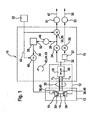
In einem mikromechanischen Drehratensensor 10 (Vibrationsgyrometer) wird zur Bestimmung einer äußeren Drehrate Ω der Corioliseffekt genutzt. Dazu wird eine bewegliche Massenstruktur 12 des Sensors 10 in einer ersten Richtung x in eine Geschwindigkeit v versetzt. Dies erfolgt mittels einer Antriebsschwingung 14, die eine Frequenz ωA aufweist. Die bewegliche Massenstruktur 12 kann eine Antriebsmasse 16 und eine Detektionsmasse 18 umfassen, wobei eine bevorzugte Schwingungsrichtung x der Antriebsmasse 16 orthogonal zu einer bevorzugten Schwingungsrichtung y der Detektionsmasse 18 orientiert ist. Durch mechanische Kopplung 20 mittels einer Federanordnung in Richtung der bevorzugten Schwingungsrichtung y der Detektionsmasse 18 wird auf die Detektionsmasse 18 eine auf die Antriebsmasse 16 wirkende Corioliskraft Fc übertragen, die aufgrund einer Drehrate Ω der Massenstruktur 12 entsteht. Da i. allg. keine exakte Orthogonalität beider Schwingungsrichtungen x, y vorliegt, entsteht infolge der Auslenkung 14 der Antriebsmasse 16 eine zweite (zu der Corioliskraft FC unterschiedliche) Kraftkomponente FQ (Quadraturanteil) in der bevorzugten Schwingungsrichtung y der Detektionsmasse 18. Der Coriolis- und der Quadraturanteil sind zueinander um 90° phasenverschoben, so dass die beiden Komponenten FC, FQ separiert ermittelt werden können, und zwar mittels einer Demodulation 24, 26 mit der Antriebsfrequenz ωA. Der Demodulator 24 erzeugt das Quadratursignal 28. Die Demodulation 26 des mittels eines Phasenschiebers 27 um 90° versetzten Detektionssignals 32 liefert das Messsignal 30, welches proportional zur Drehrate Ω ist. Die Erfassung des Detektionssignals 32 kann mittels einer open- oder closed-loop-Konfiguration erfolgen. Das Ausgangssignal 34 des Integralreglers 36 wirkt der Ursache der Quadratur Fq entgegen, indem ein in Spannung gewandeltes Ausgangssignal 34 (Quadl-Signal) auf QuadraturKompensationselektroden 38 gegeben wird. Mittels einer entsprechend ausgebildeten Elektrodenform wird eine Querkraft erzeugt, die zur Auslenkung x proportional ist, und die Richtung der Antriebsschwingung 14 soweit dreht, bis deren Kraftwirkung Fq auf die Detektionsschwingung 40 verschwindet.In a micromechanical rotation rate sensor 10 (vibration gyrometer), the Coriolis effect is used to determine an external rate of rotation Ω. For this purpose, a
Zur Funktionsprüfung wird mittels eines Testsignallieferanten 22 ein periodisches Testsignal 42 bereitgestellt, das periodische Pulse oder einen Sinusverlauf aufweist, und in den Quadraturregelkreis 44 eingespeist (siehe
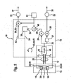
Das Auslesen des Antwortsignals 47 kann nach der Demodulation 24 des Detektionssignals 32 in den Quadraturkanal 28 erfolgen. Die Demodulation 55 mit der Frequenz ωT des Testsignals 42 plus Tiefpassfilterung 51 kann als Antwortsignal 47 ein gleichstromähnliches Signal liefern. Alternativ kann die Reihenfolge von Einspeisepunkt 48 und Auslesepunkt 50 vertauscht werden (siehe
Um eine ausreichende Genauigkeit der Funktionsprüfung zu erreichen, sollte die Bewertung des Antwortsignals 47 zumindest alle wesentlichen Einflüsse auf das Testsignal 42 berücksichtigen. Vorzugsweise ist das Antwortsignal 47 nicht von einem Einschwingverhalten der Antriebsstruktur 12 abhängig. Dies kann dadurch erreicht werden, dass die Testsignalfrequenz ωT hinreichend niedrig gewählt wird. Auch sollte das Antwortsignal 47 nicht von einer "externen" Zeitkonstanten abhängen, wie sie beispielsweise ein Taktgeber aufweist, der mit der oder mit dem die Antriebsschwingung 14 synchronisiert wird. Damit die Drehratenmessung durch die Funktionsprüfung nicht unzulässig beeinträchtigt wird, sollten eventuelle Fehlerquellen bei der Demodulation und Trennung in den Drehratenanteil und Quadraturanteil berücksichtigt werden. Deshalb kann es vorteilhaft sein, die Testsignalfrequenz ωT deutlich oberhalb einer Bandbreite eines Ausgangsfilters 53 für die Drehrateninformation 30 zu wählen, um das Testsignal 42 und Antwortsignal 47 frequenzmäßig vom Nutzsignal 30 zu trennen. Um Offset-Fehler zu vermeiden, sollte das auf das eingespeiste Testsignal 42 zu erwartende Antwortsignal 47 mittelwertfrei sein.In order to achieve a sufficient accuracy of the functional test, the evaluation of the
Das Quadratursignal ist proportional zur Kraftwirkung der Quadraturelektroden 38 und damit zum Quadrat der Potentiale der Quadraturelektroden 38. Da das Testsignal 42 auf diese Potentiale zum bestehenden Reglerpotential 34 hinzuaddiert wird, ist der Zusammenhang zwischen einem Pegel des Testsignals 42 und einem Pegel (Amplitude oder Gleichstrompegel) des Antwortsignals 47 nicht linear, sondern von einem Arbeitspunkt des Reglers 36 abhängig. Um die Arbeitspunktabhängigkeit zu berücksichtigen, werden folgende Konzepte vorgeschlagen:
- Konzept "Berechnung zur Laufzeit": Der Zusammenhang zwischen Potentialen an den Quadraturelektroden 38 und dadurch erzeugter Quadratur Fq ist analytisch beschreibbar und hängt im Wesentlichen von einer Kompensationsfähigkeit des
Sensors 10 ab. Mittels laufender Rechnung in einem Rechenwerk (beispielsweise Mikrocontroller) wird ausdem Testsignal 42und dem Antwortsignal 47 ein Maß für die Kompensationsfähigkeit extrahiert. Die Bewertung der Kompensationsfähigkeit kann im Vergleich zu einem Neuteilewert erfolgen. Ein alternatives Konzept sieht vor, dass das Rechenwerk dafür verwendet wird, ausgehend von einem aktuellen Arbeitspunkt (Quadl-Wert), einen Pegel des Testsignals 42 so zu bestimmen, dassdas Antwortsignal 47 stets einem vorgegebenen (arbeitspunktunabhängigen) Wert entspricht. Diese Art der Kompensation führt vorteilhafterweise zu einem Antwortsignal 47 mit einem arbeitspunktunabhängigen, also konstanten Signal-Rausch-Verhältnis.
- Concept "Computation at Runtime": The connection between potentials at the quadrature electrodes 38 and the resulting quadrature Fq can be described analytically and essentially depends on a compensation capability of the
Sensors 10 off. By means of a running calculation in an arithmetic unit (for example microcontroller), a measure for the compensation capability is extracted from thetest signal 42 and theresponse signal 47. The evaluation of the compensation ability can be done in comparison to a new part value. An alternative concept provides that the arithmetic unit is used, starting from a current operating point (Quadl value), to determine a level of thetest signal 42 such that theresponse signal 47 always corresponds to a predetermined (operating-point-independent) value. This type of compensation advantageously leads to aresponse signal 47 with an operating-point-independent, ie constant signal-to-noise ratio.
Konzept "Nachschlagetabelle (Lookup-Tabelle)": Um die Arbeitspunktabhängigkeit der Funktionsprüfung zu berücksichtigen, kann statt eines Rechenwerks ein nichtflüchtiger Speicher eingesetzt werden, der eine Tabelle enthält, die dazu geeignet und/oder vorgesehen ist, für die zu messenden Arbeitspunkte (Quadl-Werte) den jeweils zu erwartenden Pegel des Antwörtsignals 47 zu liefern. Der zu erwartende Pegel des Antwortsignals 47 kann mit dem tatsächlich gemessenen Pegel des Antwortsignals 47 verglichen werden. Eine alternative Möglichkeit besteht auch hier darin, das einzuspeisende Signal 42 entsprechend einer Umkehrfunktion der Arbeitspunktabhängigkeit (d.h. entsprechend einer inversen Arbeitspunktabhängigkeit) zu dosieren. Dazu enthält die Tabelle für mehrere mögliche Arbeitspunkte ein Maß für einen jeweils zu verwendenden Pegel des Test-signals, der benötigt wird, um einen vorgegebenen Sollpegel des Antwortsignals 47 zu bewirken.Concept "look-up table (lookup table)": In order to take into account the operating point dependence of the functional test, instead of an arithmetic unit, a nonvolatile memory can be used which contains a table that is suitable and / or intended for the operating points to be measured (quadrature). Values) to provide the respective expected level of the
Durch entsprechendes Design des Sensors 10 kann ein funktionaler Zusammenhang zwischen Testsignal 42 auf die Quadraturelektroden 38 und erzeugter Quadratur vereinfacht werden und damit auch der Aufwand für eine Berücksichtigung der Arbeitspunktabhängigkeit. Mittels Verwendung eigener Elektroden 39 für die Testsignaleinspeisung 48, die unterschiedlich zu denen 38 für die Quadraturregelung 36 sind, kann erreicht werden, dass ein Pegel des Antwortsignals 47 proportional zu einem Quadrat des eingespeisten Testsignals 42 ist (siehe
Claims (10)
- Rate-of-rotation sensor (10), the rate-of-rotation sensor (10) comprising a movable mass structure (12), a drive component (13) and an evaluation component (15),
the drive component (13) being suitable to impart a drive oscillation (14) to the movable mass structure (12) and/or to maintain the latter in a drive oscillation (14), and
the evaluation component (15) being suitable to measure a detection oscillation (40) of the movable mass structure (12) as a result of a rate of rotation (Q),
the movable mass structure (12) comprising a drive mass (16) and a detection mass (18),
the drive mass (16) being connected to the detection mass (18) via a mechanical coupling by means of a spring arrangement,
the drive mass (16) being movable in a drive oscillation (14),
characterized in that
quadrature compensation electrodes (38) are provided, with which the direction of the drive oscillation (14) of the drive mass (16) can be rotated until an action of force on a detection oscillation (40) of the detection mass (18) vanishes,
in that the quadrature compensation electrodes (38) are connected to a test signal supplier (22) of a test signal,
the test signal supplier (22) being set up to output the test signal to the quadrature compensation electrodes (38),
in that, in relation to a processing direction (45) of the test signal (42), a read location (50) for a response signal (47) is arranged between a feed location (48) for the test signal (42) and the quadrature compensation electrodes (38). - Rate-of-rotation sensor (10) according to Claim 1, characterized in that, in order to apply the test signal (42) to the movable mass structure (12), actuators (39) other than for quadrature compensation, in particular other electrodes (39), are provided.
- Rate-of-rotation sensor (10) according to Claim 1 or 2, characterized in that the test signal (42) causes a substantially zero-mean response signal (47).
- Rate-of-rotation sensor (10) according to one of Claims 1 to 3, characterized in that a relationship between a level of the test signal (42) and a level of the response signal (47) which the test signal (42) effects over a processing path (43) of the test signal (42) is linear.
- Method for the functional testing of a rate-of-rotation sensor (10), the method comprising the following steps:- driving a movable mass structure (12) which comprises a drive mass (16) and a detection mass (18), the drive mass (16) being operatively connected to a detection mass (18),- feeding a test signal (42) into a quadrature control loop (44) at a feed location (48) of the quadrature control loop (44);- feeding back a detection oscillation (40) of the movable mass structure (12);- acquiring a measure of the feedback from the movable mass structure (12);- reading a response signal (47) that depends on the test signal (42) from the quadrature control loop (44);characterized- in that the quadrature control loop (44) is connected to quadrature compensation electrodes (38) of the drive mass (16),- in that the detection oscillation (40) of the movable mass structure (12) is fed back by means of the quadrature compensation electrodes (38) which rotate the direction of the drive oscillation (14) of the drive mass (16) until an action of force on the detection oscillation (40) vanishes;- in that, in relation to a processing direction (45) of the test signal (42), the reading of the response signal (47) is provided between the feed location (48) and a location (49) of the feedback from the the movable mass structure (12).
- Method according to Claim 5, characterized in that a substantial part of a power spectrum of the response signal (47) lies above a bandwidth of an output filter (51) for rate-of-rotation information (30).
- Method according to Claim 5, characterized in that a substantial part of a power spectrum of the response signal (47) lies above a bandwidth of the quadrature control loop (44).
- Method according to one of Claims 5 to 7, characterized in that a frequency (ωT) of the test signal (42) is lower than an inverse control time constant of the quadrature control loop (44).
- Method according to one of Claims 5 to 8, characterized in that the test signal (42) has a sinusoidal variation.
- Method according to one of Claims 5 to 9, characterized in that the test signal (42) is metered in accordance with an inverse working point dependence of the quadrature control loop (44).
Applications Claiming Priority (2)
| Application Number | Priority Date | Filing Date | Title |
|---|---|---|---|
| DE200910003217 DE102009003217A1 (en) | 2009-05-19 | 2009-05-19 | Self-test for rotation rate sensors |
| PCT/EP2010/054479 WO2010133394A1 (en) | 2009-05-19 | 2010-04-06 | Self test for yaw rate sensors |
Publications (2)
| Publication Number | Publication Date |
|---|---|
| EP2433094A1 EP2433094A1 (en) | 2012-03-28 |
| EP2433094B1 true EP2433094B1 (en) | 2015-03-04 |
Family
ID=42224764
Family Applications (1)
| Application Number | Title | Priority Date | Filing Date |
|---|---|---|---|
| EP20100713897 Active EP2433094B1 (en) | 2009-05-19 | 2010-04-06 | Self-test for rotation rate sensors |
Country Status (5)
| Country | Link |
|---|---|
| US (2) | US8910518B2 (en) |
| EP (1) | EP2433094B1 (en) |
| JP (1) | JP5372244B2 (en) |
| DE (1) | DE102009003217A1 (en) |
| WO (1) | WO2010133394A1 (en) |
Families Citing this family (14)
| Publication number | Priority date | Publication date | Assignee | Title |
|---|---|---|---|---|
| DE102009003217A1 (en) * | 2009-05-19 | 2010-11-25 | Robert Bosch Gmbh | Self-test for rotation rate sensors |
| JP5390468B2 (en) * | 2010-05-24 | 2014-01-15 | 株式会社デンソー | Angular velocity detector |
| DE102011081026A1 (en) | 2011-08-16 | 2013-02-21 | Robert Bosch Gmbh | Method for functional testing of an inertial sensor and inertial sensor |
| ITTO20130013A1 (en) | 2013-01-09 | 2014-07-10 | St Microelectronics Srl | MICROELETTROMECHANICAL GYROSCOPE WITH COMPENSATION OF SQUARE SIGNAL COMPONENTS AND METHOD OF CONTROL OF A MICROELECTRANOMIC GYROSCOPE |
| US9109901B2 (en) * | 2013-03-08 | 2015-08-18 | Freescale Semiconductor Inc. | System and method for monitoring a gyroscope |
| CN103822623B (en) * | 2014-03-03 | 2016-09-21 | 中国兵器工业集团第二一四研究所苏州研发中心 | A kind of oscillatory type silicon micromechanical gyro quadrature error closed loop compensation circuit |
| DE102014211706A1 (en) * | 2014-06-18 | 2015-12-24 | Robert Bosch Gmbh | Sensor device and method for operating a sensor device |
| FR3079026B1 (en) * | 2018-03-15 | 2021-01-01 | Sysnav | METHOD OF CALIBRATION OF A GYROMETER EQUIPPING A VEHICLE |
| US11047684B2 (en) * | 2019-02-28 | 2021-06-29 | Nxp Usa, Inc. | System and method for continuous monitoring of a gyroscope |
| DE102019214984A1 (en) * | 2019-09-30 | 2021-04-01 | Robert Bosch Gmbh | Inertial sensor and computer-implemented method for self-calibration of an inertial sensor |
| DE102021202134A1 (en) * | 2020-03-25 | 2021-09-30 | Robert Bosch Gesellschaft mit beschränkter Haftung | Method for determining, measuring and / or monitoring properties of a sensor system |
| DE102020211308A1 (en) | 2020-09-09 | 2022-03-10 | Robert Bosch Gesellschaft mit beschränkter Haftung | Sensor system, method for generating a test signal for a sensor of a sensor system |
| DE102020213286A1 (en) * | 2020-10-21 | 2022-04-21 | Robert Bosch Gesellschaft mit beschränkter Haftung | Method for determining a phase position of a yaw rate signal or a quadrature signal, method for adapting a demodulation phase and yaw rate sensor |
| US11668585B2 (en) | 2021-08-27 | 2023-06-06 | Stmicroelectronics S.R.L. | Method for correcting gyroscope demodulation phase drift |
Family Cites Families (11)
| Publication number | Priority date | Publication date | Assignee | Title |
|---|---|---|---|---|
| US5703292A (en) * | 1994-03-28 | 1997-12-30 | The Charles Stark Draper Laboratory, Inc. | Sensor having an off-frequency drive scheme and a sense bias generator utilizing tuned circuits |
| DE4447005A1 (en) * | 1994-12-29 | 1996-07-04 | Bosch Gmbh Robert | Device for determining a rotation rate |
| DE19853063B4 (en) | 1997-11-18 | 2011-07-28 | DENSO CORPORATION, Aichi-pref. | Angular velocity sensor and diagnostic system for it |
| JP4126785B2 (en) * | 1997-11-18 | 2008-07-30 | 株式会社デンソー | Angular velocity sensor |
| DE10062347A1 (en) * | 2000-12-14 | 2002-06-20 | Bosch Gmbh Robert | Method for adjusting the phase-locked loop of an electronic evaluation device and an electronic evaluation device |
| JP4210684B2 (en) * | 2003-06-30 | 2009-01-21 | シーメンス アクチエンゲゼルシヤフト | Monitoring method of rotation speed sensor |
| US6934665B2 (en) | 2003-10-22 | 2005-08-23 | Motorola, Inc. | Electronic sensor with signal conditioning |
| DE102004061804B4 (en) * | 2004-12-22 | 2015-05-21 | Robert Bosch Gmbh | Micromechanical rotation rate sensor with error suppression |
| DE102005004775A1 (en) | 2005-02-01 | 2006-08-10 | Robert Bosch Gmbh | Sensor with self-test |
| US7677099B2 (en) | 2007-11-05 | 2010-03-16 | Invensense Inc. | Integrated microelectromechanical systems (MEMS) vibrating mass Z-axis rate sensor |
| DE102009003217A1 (en) * | 2009-05-19 | 2010-11-25 | Robert Bosch Gmbh | Self-test for rotation rate sensors |
-
2009
- 2009-05-19 DE DE200910003217 patent/DE102009003217A1/en not_active Withdrawn
-
2010
- 2010-04-06 US US13/266,408 patent/US8910518B2/en active Active
- 2010-04-06 WO PCT/EP2010/054479 patent/WO2010133394A1/en active Application Filing
- 2010-04-06 JP JP2012511210A patent/JP5372244B2/en active Active
- 2010-04-06 EP EP20100713897 patent/EP2433094B1/en active Active
-
2014
- 2014-11-13 US US14/540,298 patent/US9863781B2/en active Active
Also Published As
| Publication number | Publication date |
|---|---|
| US9863781B2 (en) | 2018-01-09 |
| WO2010133394A1 (en) | 2010-11-25 |
| EP2433094A1 (en) | 2012-03-28 |
| US20120186345A1 (en) | 2012-07-26 |
| US20150121990A1 (en) | 2015-05-07 |
| JP5372244B2 (en) | 2013-12-18 |
| DE102009003217A1 (en) | 2010-11-25 |
| US8910518B2 (en) | 2014-12-16 |
| JP2012527604A (en) | 2012-11-08 |
Similar Documents
| Publication | Publication Date | Title |
|---|---|---|
| EP2433094B1 (en) | Self-test for rotation rate sensors | |
| EP1666841B1 (en) | Self testing sensor | |
| WO2002016879A1 (en) | Method for a phase angle correction during scanning of a code track | |
| DE102012104358A1 (en) | Method and system for quadrature error compensation | |
| EP0349716A2 (en) | System for the detection of the position of moving machine parts | |
| EP0977997A2 (en) | Method for detecting the direction of rotation of a wheel by means of hall probes | |
| EP2641066A2 (en) | Method and measuring device for volume measurement and evaluation | |
| DE102004061804B4 (en) | Micromechanical rotation rate sensor with error suppression | |
| DE3642771A1 (en) | METHOD AND DEVICE FOR MEASURING THE MEASURING SIZE OF A MEASURING OBJECT | |
| DE10052609A1 (en) | Phase shift of an angular sensor compensation method in which an algorithm is used to determine a compensation value from sine and cosine values produced from a magnetic angular sensor used with a signal generator | |
| EP1853927B1 (en) | Motion sensor equipped with encoder monitoring circuit and corresponding encoder monitoring method | |
| DE3710904A1 (en) | METHOD AND ARRANGEMENT FOR EVALUATING AN ANALOG ELECTRICAL MEASURING SIZE | |
| DE102004049753B3 (en) | Method and arrangement for determining the distance of a conductive surface profiled in the direction of the distance determination from a functional surface moving relative to the surface | |
| DE102017216536B4 (en) | Method for compensating for disturbances in a measured angle signal of a magnetic angle sensor of an electrical machine and a correspondingly designed microcontroller, an electrical machine, and a computer program product | |
| DE102017126610A1 (en) | Position prediction device and position detection device | |
| EP2128570A1 (en) | Use of a measurement signal analysis of a position sensor to determine the time difference between a first and a second event | |
| DE19859828A1 (en) | Sensor device for recording a physical measured variable | |
| DE19800805B4 (en) | Method and sensor arrangement for generating a reference signal | |
| DE10247321B3 (en) | Sensing rotary motion and torque from phase measurements and computerized linear transformation, adopts iterative approximation technique | |
| WO2013013854A1 (en) | Magnetic sensor for measuring a magnetic field of a magnetic multipole and corresponding device for determining motion parameters | |
| EP2776820B1 (en) | Method for correcting measured values from a sensor element | |
| WO2013013855A1 (en) | Device for determining motion parameters | |
| DE3524530A1 (en) | Evaluating electronics for differential resistors to be used in sensors | |
| EP3312566A1 (en) | Rotary encoder to measure a variable of a rotating object | |
| EP2899512B1 (en) | Generation of an output signal |
Legal Events
| Date | Code | Title | Description |
|---|---|---|---|
| PUAI | Public reference made under article 153(3) epc to a published international application that has entered the european phase |
Free format text: ORIGINAL CODE: 0009012 |
|
| 17P | Request for examination filed |
Effective date: 20111219 |
|
| AK | Designated contracting states |
Kind code of ref document: A1 Designated state(s): AT BE BG CH CY CZ DE DK EE ES FI FR GB GR HR HU IE IS IT LI LT LU LV MC MK MT NL NO PL PT RO SE SI SK SM TR |
|
| DAX | Request for extension of the european patent (deleted) | ||
| RIC1 | Information provided on ipc code assigned before grant |
Ipc: G01C 19/5726 20120101ALI20140901BHEP Ipc: G01C 19/56 20120101AFI20140901BHEP |
|
| GRAP | Despatch of communication of intention to grant a patent |
Free format text: ORIGINAL CODE: EPIDOSNIGR1 |
|
| INTG | Intention to grant announced |
Effective date: 20141205 |
|
| GRAS | Grant fee paid |
Free format text: ORIGINAL CODE: EPIDOSNIGR3 |
|
| GRAA | (expected) grant |
Free format text: ORIGINAL CODE: 0009210 |
|
| AK | Designated contracting states |
Kind code of ref document: B1 Designated state(s): AT BE BG CH CY CZ DE DK EE ES FI FR GB GR HR HU IE IS IT LI LT LU LV MC MK MT NL NO PL PT RO SE SI SK SM TR |
|
| REG | Reference to a national code |
Ref country code: GB Ref legal event code: FG4D Free format text: NOT ENGLISH |
|
| REG | Reference to a national code |
Ref country code: CH Ref legal event code: EP |
|
| REG | Reference to a national code |
Ref country code: IE Ref legal event code: FG4D Free format text: LANGUAGE OF EP DOCUMENT: GERMAN |
|
| REG | Reference to a national code |
Ref country code: AT Ref legal event code: REF Ref document number: 714268 Country of ref document: AT Kind code of ref document: T Effective date: 20150415 |
|
| REG | Reference to a national code |
Ref country code: DE Ref legal event code: R096 Ref document number: 502010009053 Country of ref document: DE Effective date: 20150416 |
|
| REG | Reference to a national code |
Ref country code: NL Ref legal event code: VDEP Effective date: 20150304 |
|
| PG25 | Lapsed in a contracting state [announced via postgrant information from national office to epo] |
Ref country code: NO Free format text: LAPSE BECAUSE OF FAILURE TO SUBMIT A TRANSLATION OF THE DESCRIPTION OR TO PAY THE FEE WITHIN THE PRESCRIBED TIME-LIMIT Effective date: 20150604 Ref country code: LT Free format text: LAPSE BECAUSE OF FAILURE TO SUBMIT A TRANSLATION OF THE DESCRIPTION OR TO PAY THE FEE WITHIN THE PRESCRIBED TIME-LIMIT Effective date: 20150304 Ref country code: FI Free format text: LAPSE BECAUSE OF FAILURE TO SUBMIT A TRANSLATION OF THE DESCRIPTION OR TO PAY THE FEE WITHIN THE PRESCRIBED TIME-LIMIT Effective date: 20150304 Ref country code: SE Free format text: LAPSE BECAUSE OF FAILURE TO SUBMIT A TRANSLATION OF THE DESCRIPTION OR TO PAY THE FEE WITHIN THE PRESCRIBED TIME-LIMIT Effective date: 20150304 Ref country code: HR Free format text: LAPSE BECAUSE OF FAILURE TO SUBMIT A TRANSLATION OF THE DESCRIPTION OR TO PAY THE FEE WITHIN THE PRESCRIBED TIME-LIMIT Effective date: 20150304 Ref country code: ES Free format text: LAPSE BECAUSE OF FAILURE TO SUBMIT A TRANSLATION OF THE DESCRIPTION OR TO PAY THE FEE WITHIN THE PRESCRIBED TIME-LIMIT Effective date: 20150304 |
|
| REG | Reference to a national code |
Ref country code: LT Ref legal event code: MG4D |
|
| PG25 | Lapsed in a contracting state [announced via postgrant information from national office to epo] |
Ref country code: LV Free format text: LAPSE BECAUSE OF FAILURE TO SUBMIT A TRANSLATION OF THE DESCRIPTION OR TO PAY THE FEE WITHIN THE PRESCRIBED TIME-LIMIT Effective date: 20150304 Ref country code: GR Free format text: LAPSE BECAUSE OF FAILURE TO SUBMIT A TRANSLATION OF THE DESCRIPTION OR TO PAY THE FEE WITHIN THE PRESCRIBED TIME-LIMIT Effective date: 20150605 |
|
| PG25 | Lapsed in a contracting state [announced via postgrant information from national office to epo] |
Ref country code: NL Free format text: LAPSE BECAUSE OF FAILURE TO SUBMIT A TRANSLATION OF THE DESCRIPTION OR TO PAY THE FEE WITHIN THE PRESCRIBED TIME-LIMIT Effective date: 20150304 |
|
| PG25 | Lapsed in a contracting state [announced via postgrant information from national office to epo] |
Ref country code: CZ Free format text: LAPSE BECAUSE OF FAILURE TO SUBMIT A TRANSLATION OF THE DESCRIPTION OR TO PAY THE FEE WITHIN THE PRESCRIBED TIME-LIMIT Effective date: 20150304 Ref country code: PT Free format text: LAPSE BECAUSE OF FAILURE TO SUBMIT A TRANSLATION OF THE DESCRIPTION OR TO PAY THE FEE WITHIN THE PRESCRIBED TIME-LIMIT Effective date: 20150706 Ref country code: RO Free format text: LAPSE BECAUSE OF FAILURE TO SUBMIT A TRANSLATION OF THE DESCRIPTION OR TO PAY THE FEE WITHIN THE PRESCRIBED TIME-LIMIT Effective date: 20150304 Ref country code: EE Free format text: LAPSE BECAUSE OF FAILURE TO SUBMIT A TRANSLATION OF THE DESCRIPTION OR TO PAY THE FEE WITHIN THE PRESCRIBED TIME-LIMIT Effective date: 20150304 Ref country code: SK Free format text: LAPSE BECAUSE OF FAILURE TO SUBMIT A TRANSLATION OF THE DESCRIPTION OR TO PAY THE FEE WITHIN THE PRESCRIBED TIME-LIMIT Effective date: 20150304 |
|
| PG25 | Lapsed in a contracting state [announced via postgrant information from national office to epo] |
Ref country code: PL Free format text: LAPSE BECAUSE OF FAILURE TO SUBMIT A TRANSLATION OF THE DESCRIPTION OR TO PAY THE FEE WITHIN THE PRESCRIBED TIME-LIMIT Effective date: 20150304 Ref country code: IS Free format text: LAPSE BECAUSE OF FAILURE TO SUBMIT A TRANSLATION OF THE DESCRIPTION OR TO PAY THE FEE WITHIN THE PRESCRIBED TIME-LIMIT Effective date: 20150704 Ref country code: MC Free format text: LAPSE BECAUSE OF FAILURE TO SUBMIT A TRANSLATION OF THE DESCRIPTION OR TO PAY THE FEE WITHIN THE PRESCRIBED TIME-LIMIT Effective date: 20150304 |
|
| REG | Reference to a national code |
Ref country code: CH Ref legal event code: PL |
|
| REG | Reference to a national code |
Ref country code: DE Ref legal event code: R097 Ref document number: 502010009053 Country of ref document: DE |
|
| PLBE | No opposition filed within time limit |
Free format text: ORIGINAL CODE: 0009261 |
|
| STAA | Information on the status of an ep patent application or granted ep patent |
Free format text: STATUS: NO OPPOSITION FILED WITHIN TIME LIMIT |
|
| REG | Reference to a national code |
Ref country code: IE Ref legal event code: MM4A |
|
| PG25 | Lapsed in a contracting state [announced via postgrant information from national office to epo] |
Ref country code: DK Free format text: LAPSE BECAUSE OF FAILURE TO SUBMIT A TRANSLATION OF THE DESCRIPTION OR TO PAY THE FEE WITHIN THE PRESCRIBED TIME-LIMIT Effective date: 20150304 Ref country code: LI Free format text: LAPSE BECAUSE OF NON-PAYMENT OF DUE FEES Effective date: 20150430 Ref country code: CH Free format text: LAPSE BECAUSE OF NON-PAYMENT OF DUE FEES Effective date: 20150430 |
|
| 26N | No opposition filed |
Effective date: 20151207 |
|
| GBPC | Gb: european patent ceased through non-payment of renewal fee |
Effective date: 20150604 |
|
| PG25 | Lapsed in a contracting state [announced via postgrant information from national office to epo] |
Ref country code: SI Free format text: LAPSE BECAUSE OF FAILURE TO SUBMIT A TRANSLATION OF THE DESCRIPTION OR TO PAY THE FEE WITHIN THE PRESCRIBED TIME-LIMIT Effective date: 20150304 |
|
| REG | Reference to a national code |
Ref country code: FR Ref legal event code: PLFP Year of fee payment: 7 |
|
| PG25 | Lapsed in a contracting state [announced via postgrant information from national office to epo] |
Ref country code: GB Free format text: LAPSE BECAUSE OF NON-PAYMENT OF DUE FEES Effective date: 20150604 Ref country code: IE Free format text: LAPSE BECAUSE OF NON-PAYMENT OF DUE FEES Effective date: 20150406 |
|
| REG | Reference to a national code |
Ref country code: AT Ref legal event code: MM01 Ref document number: 714268 Country of ref document: AT Kind code of ref document: T Effective date: 20150406 |
|
| PG25 | Lapsed in a contracting state [announced via postgrant information from national office to epo] |
Ref country code: AT Free format text: LAPSE BECAUSE OF NON-PAYMENT OF DUE FEES Effective date: 20150406 |
|
| PG25 | Lapsed in a contracting state [announced via postgrant information from national office to epo] |
Ref country code: MT Free format text: LAPSE BECAUSE OF FAILURE TO SUBMIT A TRANSLATION OF THE DESCRIPTION OR TO PAY THE FEE WITHIN THE PRESCRIBED TIME-LIMIT Effective date: 20150304 |
|
| REG | Reference to a national code |
Ref country code: FR Ref legal event code: PLFP Year of fee payment: 8 |
|
| PG25 | Lapsed in a contracting state [announced via postgrant information from national office to epo] |
Ref country code: SM Free format text: LAPSE BECAUSE OF FAILURE TO SUBMIT A TRANSLATION OF THE DESCRIPTION OR TO PAY THE FEE WITHIN THE PRESCRIBED TIME-LIMIT Effective date: 20150304 Ref country code: HU Free format text: LAPSE BECAUSE OF FAILURE TO SUBMIT A TRANSLATION OF THE DESCRIPTION OR TO PAY THE FEE WITHIN THE PRESCRIBED TIME-LIMIT; INVALID AB INITIO Effective date: 20100406 Ref country code: BG Free format text: LAPSE BECAUSE OF FAILURE TO SUBMIT A TRANSLATION OF THE DESCRIPTION OR TO PAY THE FEE WITHIN THE PRESCRIBED TIME-LIMIT Effective date: 20150304 |
|
| PG25 | Lapsed in a contracting state [announced via postgrant information from national office to epo] |
Ref country code: CY Free format text: LAPSE BECAUSE OF FAILURE TO SUBMIT A TRANSLATION OF THE DESCRIPTION OR TO PAY THE FEE WITHIN THE PRESCRIBED TIME-LIMIT Effective date: 20150304 |
|
| PG25 | Lapsed in a contracting state [announced via postgrant information from national office to epo] |
Ref country code: BE Free format text: LAPSE BECAUSE OF NON-PAYMENT OF DUE FEES Effective date: 20150430 |
|
| PG25 | Lapsed in a contracting state [announced via postgrant information from national office to epo] |
Ref country code: TR Free format text: LAPSE BECAUSE OF FAILURE TO SUBMIT A TRANSLATION OF THE DESCRIPTION OR TO PAY THE FEE WITHIN THE PRESCRIBED TIME-LIMIT Effective date: 20150304 |
|
| PG25 | Lapsed in a contracting state [announced via postgrant information from national office to epo] |
Ref country code: LU Free format text: LAPSE BECAUSE OF NON-PAYMENT OF DUE FEES Effective date: 20150406 |
|
| REG | Reference to a national code |
Ref country code: FR Ref legal event code: PLFP Year of fee payment: 9 |
|
| PG25 | Lapsed in a contracting state [announced via postgrant information from national office to epo] |
Ref country code: MK Free format text: LAPSE BECAUSE OF FAILURE TO SUBMIT A TRANSLATION OF THE DESCRIPTION OR TO PAY THE FEE WITHIN THE PRESCRIBED TIME-LIMIT Effective date: 20150304 |
|
| P01 | Opt-out of the competence of the unified patent court (upc) registered |
Effective date: 20230509 |
|
| PGFP | Annual fee paid to national office [announced via postgrant information from national office to epo] |
Ref country code: IT Payment date: 20230428 Year of fee payment: 14 Ref country code: FR Payment date: 20230417 Year of fee payment: 14 Ref country code: DE Payment date: 20230627 Year of fee payment: 14 |