EP2432645B1 - Printhead with porous catcher - Google Patents
Printhead with porous catcher Download PDFInfo
- Publication number
- EP2432645B1 EP2432645B1 EP10724157A EP10724157A EP2432645B1 EP 2432645 B1 EP2432645 B1 EP 2432645B1 EP 10724157 A EP10724157 A EP 10724157A EP 10724157 A EP10724157 A EP 10724157A EP 2432645 B1 EP2432645 B1 EP 2432645B1
- Authority
- EP
- European Patent Office
- Prior art keywords
- pores
- liquid
- contact structure
- printhead
- material layer
- Prior art date
- Legal status (The legal status is an assumption and is not a legal conclusion. Google has not performed a legal analysis and makes no representation as to the accuracy of the status listed.)
- Not-in-force
Links
Images


Classifications
-
- B—PERFORMING OPERATIONS; TRANSPORTING
- B41—PRINTING; LINING MACHINES; TYPEWRITERS; STAMPS
- B41J—TYPEWRITERS; SELECTIVE PRINTING MECHANISMS, i.e. MECHANISMS PRINTING OTHERWISE THAN FROM A FORME; CORRECTION OF TYPOGRAPHICAL ERRORS
- B41J2/00—Typewriters or selective printing mechanisms characterised by the printing or marking process for which they are designed
- B41J2/005—Typewriters or selective printing mechanisms characterised by the printing or marking process for which they are designed characterised by bringing liquid or particles selectively into contact with a printing material
- B41J2/01—Ink jet
- B41J2/17—Ink jet characterised by ink handling
- B41J2/18—Ink recirculation systems
- B41J2/185—Ink-collectors; Ink-catchers
Description
- This invention relates generally to the field of digitally controlled printing systems, and in particular to continuous printing systems.
- Continuous inkjet printing uses a pressurized liquid source that produces a stream of drops some of which are selected to contact a print media (often referred to a "print drops") while other are selected to be collected and either recycled or discarded (often referred to as "non-print drops"). For example, when no print is desired, the drops are deflected into a capturing mechanism (commonly referred to as a catcher, interceptor, or gutter) and either recycled or discarded. When printing is desired, the drops are not deflected and allowed to strike a print media. Alternatively, deflected drops can be allowed to strike the print media, while non-deflected drops are collected in the capturing mechanism.
- Drop placement accuracy of print drops is critical in order to maintain image quality. Liquid build up on the drop contact face of the catcher can adversely affect drop placement accuracy. As such, there is a continuing need to provide an improved catcher for these types of printing systems.
-
EP-A-1 308 278 discloses a continuous inkjet printer having a catcher with a porous element as ink drop contact structure. An ink recovery conduit communicates with the back side of the porous element and operates at a reduced gas pressure relative to the ambient pressure. The pressure reduction in the conduit is sufficient to draw in recovered ink but is not large enough to cause significant air flow through porous element. In this manner of operation, foaming of the recovered ink is reduced but not eliminated and foaming in the recovered ink may occur. - According to one feature of the present invention, a printhead includes a catcher and a negative pressure source. The catcher includes a liquid drop contact structure. The liquid drop contact structure includes a plurality of pores, each of the plurality of pores having a substantially uniform size when compared to each other. The plurality of pores have a critical pressure point above which air can displace liquid from the plurality of pores. The negative pressure source is in fluid communication with the plurality of pores of the liquid contact structure. The negative pressure source includes a pressure regulator to control the negative pressure such that the negative pressure remains below the critical pressure point of the plurality of pores of the liquid drop contact structure.
- According to another feature of the present invention, a method of printing includes providing a catcher including a liquid drop contact structure, the liquid drop contact structure including a plurality of pores, each of the plurality of pores having a substantially uniform size when compared to each other, the plurality of pores having a critical pressure point above which air can displace liquid from the plurality of pores; providing a negative pressure source in fluid communication with the plurality of pores of the liquid contact structure; regulating the negative pressure using a pressure regulator such that the negative pressure remains below the critical pressure point of the plurality of pores of the liquid drop contact structure; ejecting liquid drops from a jetting module; and causing some of the liquid droplets ejected from the jetting module to contact the liquid drop contact structure, the liquid droplets displacing air from the plurality of pores after contacting the liquid drop contact structure.
- In the detailed description of the example embodiments of the invention presented below, reference is made to the accompanying drawings, in which:
-
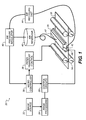
FIG. 1 is a schematic diagram of an example embodiment of a printer system made in accordance with the present invention; -
FIG. 2 is a schematic view of an example embodiment of a continuous printhead made in accordance with the present invention; -
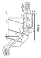
FIG. 3 is a schematic view of an example embodiment of a continuous printhead made in accordance with the present invention; -
FIG. 4 is a schematic side view of an example embodiment of a liquid drop contact structure according to the present invention; -
FIG. 5 is a schematic side view of an example embodiment of a liquid drop contact structure according to the present invention including a reinforcing structure having fluid channels with varying cross-sections; -
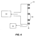
FIG. 6 is a schematic top view of an example embodiment of a liquid drop contact structure according to the present invention including a reinforcing structure located outside of the liquid drop contact structure; -
FIG. 7 is a schematic side view of an example embodiment of a liquid drop contact structure according to the present invention including two reinforcing structures; -
FIGS. 8(A)-8(F) are schematic views of an example embodiment of a method for manufacturing a liquid drop contact structure according to the present invention; -
FIGS. 9(A)-9(F) are schematic views of another example embodiment of a method for manufacturing a liquid drop contact structure according to the present invention; -
FIGS. 10(A)-10(D) are schematic views of another example embodiment of a method for manufacturing a liquid drop contact structure according to the present invention; -
FIGS. 11(A)-11(E) are schematic views of an example embodiment of a method for manufacturing a liquid drop contact structure according to the present invention where the catcher face material layer is etched and forms a mask for use in etching the reinforcing structure material layer; -
FIGS. 12(A)-12(D) are schematic views of an example embodiment of a method for manufacturing a liquid drop contact structure according to the present invention including the use of an etch stop between the catcher face material layer and the reinforcing structure material layer; -
FIGS. 13(A)-13(F) are schematic views of an example embodiment of a method for manufacturing a liquid drop contact structure according to the present invention including the use of an etch stop between the reinforcing structure material layer and the substrate; -
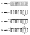
FIGS. 14(A)-14(D) are schematic views of another example embodiment of a method for manufacturing a liquid drop contact structure according to the present invention; and -
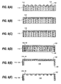
FIGS. 15(A)-15(F) are schematic views of example arrangements of the pores of the liquid drop contact structure. - The present description will be directed in particular to elements forming part of, or cooperating more directly with, apparatus in accordance with the present invention. It is to be understood that elements not specifically shown or described may take various forms well known to those skilled in the art. In the following description and drawings, identical reference numerals have been used, where possible, to designate identical elements.
- The example embodiments of the present invention are illustrated schematically and not to scale for the sake of clarity. One of the ordinary skills in the art will be able to readily determine the specific size and interconnections of the elements of the example embodiments of the present invention.
- As described herein, the example embodiments of the present invention provide a printhead and printhead components typically used in inkjet printing systems. However, many other applications are emerging which use inkjet printheads to emit liquids (other than inks) that need to be finely metered and deposited with high spatial precision. As such, as described herein, the terms "liquid" and "ink" refer to any material that can be ejected by the printhead or printhead components described below.
- Referring to
FIG. 1 , a continuous inkjet printer system 20 includes animage source 22 such as a scanner or computer which provides raster image data, outline image data in the form of a page description language, or other forms of digital image data. This image data is converted to half-toned bitmap image data by animage processing unit 24 which also stores the image data in memory. A plurality of drop formingmechanism control circuits 26 read data from the image memory and apply time-varying electrical pulses to a drop forming device(s) 28 that are associated with one or more nozzles of aprinthead 30. These pulses are applied at an appropriate time, and to the appropriate nozzle, so that drops formed from a continuous ink jet stream will form spots on arecording medium 32 in the appropriate position designated by the data in the image memory. -
Recording medium 32 is moved relative toprinthead 30 by a recordingmedium transport system 34, which is electronically controlled by a recording mediumtransport control system 36, and which in turn is controlled by a micro-controller 38. The recording medium transport system shown inFIG. 1 is a schematic only, and many different mechanical configurations are possible. For example, a transfer roller could be used as recordingmedium transport system 34 to facilitate transfer of the ink drops to recordingmedium 32. Such transfer roller technology is well known in the art. In the case of page width printheads, it is most convenient to move recordingmedium 32 past a stationary printhead. However, in the case of scanning print systems, it is usually most convenient to move the printhead along one axis (the sub-scanning direction) and the recording medium along an orthogonal axis (the main scanning direction) in a relative raster motion. - Ink is contained in an
ink reservoir 40 under pressure. In the non-printing state, continuous ink jet drop streams are unable to reach recordingmedium 32 due to anink catcher 42 that blocks the stream and which may allow a portion of the ink to be recycled by anink recycling unit 44. The ink recycling unit reconditions the ink and feeds it back toreservoir 40. Such ink recycling units are well known in the art. The ink pressure suitable for optimal operation will depend on a number of factors, including geometry and thermal properties of the nozzles and thermal properties of the ink. A constant ink pressure can be achieved by applying pressure to inkreservoir 40 under the control ofink pressure regulator 46. Alternatively, the ink reservoir can be left unpressurized, or even under a reduced pressure (vacuum), and a pump is employed to deliver ink from the ink reservoir under pressure to theprinthead 30. In such an embodiment, theink pressure regulator 46 can comprise an ink pump control system. As shown inFIG. 1 ,catcher 42 is a type of catcher commonly referred to as a "knife edge" catcher. - The ink is distributed to
printhead 30 through anink channel 47. The ink preferably flows through slots or holes etched through a silicon substrate ofprinthead 30 to its front surface, where a plurality of nozzles and drop forming mechanisms, for example, heaters, are situated. Whenprinthead 30 is fabricated from silicon, drop formingmechanism control circuits 26 can be integrated with the printhead.Printhead 30 also includes a deflection mechanism (not shown inFIG. 1 ) which is described in more detail below with reference toFIGS. 2 and3 . - Referring to
FIG. 2 , a schematic view of continuousliquid printhead 30 is shown. A jettingmodule 48 ofprinthead 30 includes an array or a plurality ofnozzles 50 formed in anozzle plate 49. InFIG. 2 ,nozzle plate 49 is affixed to jettingmodule 48. However, as shown inFIG. 3 ,nozzle plate 49 can be integrally formed with jettingmodule 48. - Liquid, for example, ink, is emitted under pressure through each
nozzle 50 of the array to form filaments ofliquid 52. InFIG. 2 , the array or plurality of nozzles extends into and out of the figure. - Jetting
module 48 is operable to form liquid drops having a first size and liquid drops having a second size through each nozzle. To accomplish this, jettingmodule 48 includes a drop stimulation or drop formingdevice 28, for example, a heater or a piezoelectric actuator, that, when selectively activated, perturbs each filament ofliquid 52, for example, ink, to induce portions of each filament to breakoff from the filament and coalesce to form drops 54, 56. - In
FIG. 2 , drop formingdevice 28 is aheater 51 located in anozzle plate 49 on one or both sides ofnozzle 50. This type of drop formation is known and has been described in, for example,US Patent No. 6,457,807 B1, issued to Hawkins et al., on October 1, 2002 ;US Patent No. 6,491,362 B1, issued to Jeanmaire, on December 10, 2002 ;US Patent No. 6,505,921 B2, issued to Chwalek et al., on January 14, 2003 ;US Patent No. 6,554,410 B2, issued to Jeanmaire et al., on April 29, 2003 ;US Patent No. 6,575,566 B1, issued to Jeanmaire et al., on June 10, 2003 ;US Patent No. 6,588,888 B2, issued to Jeanmaire et al., on July 8, 2003 ;US Patent No. 6,793,328 B2, issued to Jeanmaire, on September 21, 2004 ;US Patent No. 6,827,429 B2, issued to Jeanmaire et al., on December 7, 2004 ; andUS Patent No. 6,851,796 B2, issued to Jeanmaire et al., on February 8, 2005 . - Typically, one
drop forming device 28 is associated with eachnozzle 50 of the nozzle array. However, adrop forming device 28 can be associated with groups ofnozzles 50 or all ofnozzles 50 of the nozzle array. - When
printhead 30 is in operation, drops 54, 56 are typically created in a plurality of sizes, for example, in the form oflarge drops 56, a first size, andsmall drops 54, a second size. The ratio of the mass of the large drops 56 to the mass of the small drops 54 is typically approximately an integer between 2 and 10. Adrop stream 58 including drops 54, 56 follows a drop path ortrajectory 57. -
Printhead 30 also includes a gasflow deflection mechanism 60 that directs a flow ofgas 62, for example, air, past a portion of thedrop trajectory 57. This portion of the drop trajectory is called thedeflection zone 64. As the flow ofgas 62 interacts withdrops deflection zone 64 it alters the drop trajectories. As the drop trajectories pass out of thedeflection zone 64 they are traveling at an angle, called a deflection angle, relative to theundeflected drop trajectory 57. - Small drops 54 are more affected by the flow of gas than are
large drops 56 so that thesmall drop trajectory 66 diverges from thelarge drop trajectory 68. That is, the deflection angle forsmall drops 54 is larger than for large drops 56. The flow ofgas 62 provides sufficient drop deflection and therefore sufficient divergence of the small and large drop trajectories so that catcher 42 (shown inFIGS. 1 and3 ) can be positioned to intercept one of thesmall drop trajectory 66 and thelarge drop trajectory 68 so that drops following the trajectory are collected bycatcher 42 while drops following the other trajectory bypass the catcher and impinge a recording medium 32 (shown inFIGS. 1 and3 ). - When
catcher 42 is positioned to interceptlarge drop trajectory 68, small drops 54 are deflected sufficiently to avoid contact withcatcher 42 and strike the print media. As the small drops are printed, this is called small drop print mode. Whencatcher 42 is positioned to interceptsmall drop trajectory 66, large drops 56 are the drops that print. This is referred to as large drop print mode. - Referring to
FIG. 3 , jettingmodule 48 includes an array or a plurality ofnozzles 50. Liquid, for example, ink, supplied throughchannel 47, is emitted under pressure through eachnozzle 50 of the array to form filaments ofliquid 52. InFIG. 3 , the array or plurality ofnozzles 50 extends into and out of the figure. - Drop stimulation or drop forming device 28 (shown in
FIGS. 1 and2 ) associated with jettingmodule 48 is selectively actuated to perturb the filament ofliquid 52 to induce portions of the filament to break off from the filament to form drops. In this way, drops are selectively created in the form of large drops and small drops that travel toward arecording medium 32. - Positive pressure
gas flow structure 61 of gasflow deflection mechanism 60 is located on a first side ofdrop trajectory 57. Positive pressuregas flow structure 61 includes firstgas flow duct 72 that includes alower wall 74 and anupper wall 76.Gas flow duct 72 directs gas supplied from apositive pressure source 92 at downward angle θ of approximately a 45° towarddrop deflection zone 64. An optional seal(s) 84 provides an air seal between jettingmodule 48 andupper wall 76 ofgas flow duct 72. -
Upper wall 76 ofgas flow duct 72 does not need to extend to drop deflection zone 64 (as shown inFIG. 2 ). InFIG. 3 ,upper wall 76 ends at awall 96 of jettingmodule 48.Wall 96 of jettingmodule 48 serves as a portion ofupper wall 76 ending atdrop deflection zone 64. - Negative pressure
gas flow structure 63 of gasflow deflection mechanism 60 is located on a second side ofdrop trajectory 57. Negative pressure gas flow structure includes a secondgas flow duct 78 located betweencatcher 42 and anupper wall 82 that exhausts gas flow fromdeflection zone 64.Second duct 78 is connected to anegative pressure source 94 that is used to help remove gas flowing throughsecond duct 78. An optional seal(s) 84 provides an air seal between jettingmodule 48 andupper wall 82. - As shown in
FIG. 3 , gasflow deflection mechanism 60 includespositive pressure source 92 andnegative pressure source 94. However, depending on the specific application contemplated, gasflow deflection mechanism 60 can include only one ofpositive pressure source 92 andnegative pressure source 94. Furthermore, the deflection mechanism is not limited to a gas flow deflection mechanism. For example, electrostatic or thermal deflection mechanisms can be used. - Gas supplied by first
gas flow duct 72 is directed into thedrop deflection zone 64, where it causeslarge drops 56 to followlarge drop trajectory 68 andsmall drops 54 to followsmall drop trajectory 66. As shown inFIG. 3 ,small drop trajectory 66 is intercepted by afront face 90 ofcatcher 42. Small drops 54contact face 90 and flow downface 90 and into aliquid return duct 86 located or formed betweencatcher 42 and aplate 88. Collected liquid is either recycled and returned to ink reservoir 40 (shown inFIG. 1 ) for reuse or discarded. Large drops 56bypass catcher 42 and travel on torecording medium 32. Alternatively,catcher 42 can be positioned to interceptlarge drop trajectory 68. Large drops 56contact catcher 42 and flow into a liquid return duct located or formed incatcher 42. Collected liquid is either recycled for reuse or discarded. In some embodiments, a negative pressure source is attached toliquid return duct 86 to aid in the removal of ink from the duct. As shown inFIG. 3 ,catcher 42 is a type of catcher commonly referred to as a "Coanda" catcher. - Referring to
FIG. 4 , an example embodiment of acatcher 42 having afront face 90 including a liquiddrop contact structure 100 upon which the non-print drops 54 impinge is shown. The liquiddrop contact structure 100 includes a plurality ofpores 102 distinct from theliquid return duct 86, each of thepores 102 having a substantially uniform size when compared to each other. - Some example two dimensional arrangements of the
pores 102 are shown inFIGS. 15(A)-(F) , although the pores can be arranged in many other designs, depending on the specific application contemplated. The pores can be arranged with an equal density across the face of the catcher (as shown inFIGS.15(A)-(F) ) or can have a varying density across the width or height of the catcher face. Furthermore, the shape of the pores is not limited to being circular. The pores can be square (as shown inFIG. 15(C) ), rectangular (as shown inFIGS. 15(A) and (B) ), elliptical (as shown inFIG. 15(D) ), or any other shape suitable for the specific application contemplated. - Referring back to
FIG. 4 , the plurality ofpores 102 has a critical pressure point above which air can displace liquid from the plurality of pores. Below this critical pressure point, air can not displace liquid from the pores, as a result air cannot be passed through the pores, but the liquid can flow freely through the pores. The critical pressure point is a function of the surface tension of the liquid, the wetting or contact angle of the liquid with the liquiddrop contact structure 100, and the size of thepores 102. The flow of fluid through thepores 102 is limited by the viscous drag on the fluid as it flows through thepores 102. By maintaining a vacuum level inside liquid drop contact structure that is such that the pressure drop across the pores is less than the critical pressure, ink can be pulled through the pores without ingesting any air through the pores. By eliminating the ingestion of air in this manner, problems such as the creation of foam in the ink return line can be reduced or even eliminated. - Both the critical pressure at which air can displace liquid from the pores and the flow rate of liquid through the pores depend on the pore size with the critical pressure dropping with increased pore size and the rate at which liquid can flow through the pores. Therefore it is desirable to have large pores to allow for rapid fluid removal and desirable to have pores small or at least less than some limiting size to prevent the ingestion of air. As a result of these competing requirements, it is desirable for the pores to have a substantially uniform size less than the size at which air can be ingested for the vacuum levels employed. As mentioned above, the critical pressure point depends on the wetting angle of the liquid with the liquid drop contract structure, or at least on the wetting angle to the wall of the pores with more wettable surfaces yielding higher critical pressures. It is therefore desirable for the walls of the pores to be made of a highly wettable material. For water based liquids, for example, this means that the portion of the liquid drop contact structure including the plurality of pores is made from a hydrophilic material. With an appropriate liquid
drop contact structure 100, having proper pore size, surface area of the structure, and liquid wetting characteristics, any desired flow rate of liquid through the liquiddrop contact structure 100 can be obtained before the pressure drop across the liquiddrop contact structure 100 exceeds the critical pressure point. - In order to maintain the appropriate pressure drop, a
negative pressure source 104 is in fluid communication with the plurality ofpores 102 of theliquid contact structure 100. Thenegative pressure source 104 includes apressure regulator 106 which serves to control the negative pressure such that the negative pressure remains below the critical pressure point of the plurality ofpores 102 of the liquiddrop contact structure 100. The use of a singlenegative pressure source 104 with a differential pressure regulator allows the vacuum level to be varied over time within a pressure range below the critical pressure point as needed to accommodate changes or different operating conditions (for example, times when greater amounts of liquid are contacting the catcher face and times when lesser amounts of liquid is contacting the catcher face) while still maintaining the desired pressure drop across the liquiddrop contact structure 100. Alternatively, the negative pressure provided by the negative pressure source can be maintained at a substantially constant pressure level below the critical pressure point of the plurality of pores of the liquid drop contact structure throughout printhead operation. - During printhead operation, the non-printing drops 54 strike the liquid
drop contact structure 100 and are pulled into the structure through thepores 102. Theface 90 including thepores 102 should be thin to minimize the flow impedance across the face, as a large flow impedance limits the removal rate of the liquid from the liquiddrop contact structure 100 and can ultimately affect print quality. Thecatcher face 90 is preferably constructed from dielectric materials such as silicon oxide, silicon nitride, or silicon carbide, metals such as tantalum , polymeric materials, or silicon, although other materials can be used depending on the specific application contemplated. - In order to support the thin porous
drop contact face 90 and provide rigidity, a reinforcingstructure 108 is in mechanical contact with the liquiddrop contact structure 100, as shown inFIG. 4 . As used herein, the term "mechanical contact" means that the structures are mechanically coupled together, but are not necessarily in direct contact. The reinforcing structure should be made of a flexible material, which provides the enhanced mechanical strength without adding too much flow resistance. Examples of suitable flexible materials are metals such as tantalum, polymers such as polyimide or SU-8 (commercially available from Microchem Corp., Newton, Massachusetts) or dielectric materials, although other materials can be suitable, depending on the specific application. This reinforcingstructure 108 includes a plurality offluid channels 110 which are in fluid communication with the recycling unit or a waste tank, depending on the application contemplated, through a fluid return line. Thefluid channels 110 of the reinforcingstructure 108 include openings that are larger than the size of thepores 102 in the liquiddrop contact structure 100. The large size of openings results in a lower fluid impedance when compared to the fluid impedance of the plurality ofpores 102 of the liquiddrop contact structure 100, allowing the fluid to flow more quickly and easily through thefluid channels 110. InFIG. 4 , the reinforcingstructure 108 is located on an internal side (inside) of the liquiddrop contact structure 100. - As typically the non-print drops 54 don't impinge on the
front face 90 of thecatcher 42 all the way at the top of this face, in some embodiments the catcher face above the drop impact region can include anon-porous section 111. In some embodiments, all the liquid from the drops striking thefront face 90 of the catcher is removed from the catcher face via thepores 102. In other embodiments, such as is shown inFIG. 4 , only a portion of the liquid from the drops striking the front face of the catcher is extracted through thepores 102. In such embodiments, the radius ofedge 112 enables fluid flowing down the face to flow around the edge and enter theliquid return duct 86. Liquid entering the liquid return duct is extracted from there and returned to the ink reservoir by means ofadditional vacuum source 114. - Reinforcing
structure 108 can be one continuous layer, as shown inFIG. 4 , but, as shown inFIG. 5 , it need not be uniform and can be composed of multiple layers with varying thicknesses (often referred to a being stepped or tiered). In other words, thefluid channels 110 of the reinforcingstructure 108 can have varying cross-sections over the length of the fluid channel. The embodiment inFIG. 5 can be manufactured using a multi-layer etch, for example. The use of a multi-layer etch process also allows for the creation of cross-flow channels in the reinforcing structure, depending on the specific application contemplated. - In some embodiments, such as the one shown in
FIG. 6 , the reinforcingstructure 108 is located on an external side (outside) of the liquiddrop contact structure 100. Additionally, in other embodiments, such as the one inFIG. 7 , two reinforcingstructures structure 108B can be located on the outside of the liquiddrop contact structure 100 and one reinforcingstructure 108A can be located on the inside of the liquiddrop contact structure 100. To minimize mist that might be created as the non-print drops strike the front face of the catcher, it is preferable to align the reinforcingstructures 108 on the outside of the liquiddrop contact structure 100 with the trajectory of the drops. However, other geometries can also be employed. - In some embodiments, the liquid drop contact structure can be brought into fluid communication with a fluid source. The fluid source can include an ink reservoir, a cleaning fluid reservoir, or another fluid source depending on the specific application contemplated. When the liquid drop contact structure is in fluid communication with a fluid source, the fluid can be introduced into the liquid drop contact structure to maintain the wetness of pores or to replenish the pores with fresh fluid. For example, during a start-up sequence, cleaning fluid can be introduced to the liquid drop contact structure and pores so as to dissolve any dried ink and wash away any debris while wetting the pores to enhance the absorption of drops contacting the liquid drop contact structure by the pores.
- Advantageously, the catcher of the present invention maximizes liquid removal rates with a reduced drop contact surface area while maintaining structural robustness. Additionally, the catcher of the present invention reduces liquid build up on the drop contact surface of the catcher and reduces the likelihood of air being ingested into the catcher.
- The porous catcher is manufactured via a multi-step etching method using photolithographic masks. Generally, a catcher face material layer is provided on a reinforcing structure material layer. As discussed above, materials suitable for the catcher face material layer include, but are not limited to, dielectric materials such as silicon oxide, silicon nitride, or silicon carbide, metals such as tantalum, polymeric materials, or silicon. The reinforcing structure material layer is a thin flexible material layer, which provides the enhanced mechanical strength without adding too much flow resistance. Examples of flexible materials are metals such as tantalum, polymers such as polyimide or SU-8, and dielectric materials. The specific materials for each layer depend on the specific application contemplated. The step of providing a catcher face material layer on a reinforcing structure material layer can be achieved by lamination of the two layers or by a deposition process, depending on the specific application contemplated and the particular materials chosen. A first etching process is used to form the pores in the catcher face material layer, and a second etching process is used to form the openings in the reinforcing structure material layer. These steps can be accomplished in various orders, as will be described below. The specific etching processes chosen depend on the materials selected for the catcher face material layer and the reinforcing structure material layer. The
pores 102 of thecatcher face 90 and the openings in the reinforcing structure material layer are fluidically connected by way of a material removal process, and the reinforcing structure is in mechanical contact with thecatcher face 90. Thus, the reinforcing structure can be in direct contact with the catcher face as shown inFIGS. 4-7 , or the reinforcing structure can be in contact with other layers which allow it to be mechanically coupled to thecatcher face 90, as shown inFIG. 12 . - One example embodiment of a manufacturing method is shown in
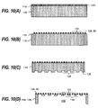
FIGS. 8(A)-(F) . InFIG. 8(A) , the reinforcingstructure material layer 116 is masked and etched on afirst side 118 to createopenings 120 in the reinforcingstructure material layer 116. Theseopenings 120 correspond to thefluid return channels 110. The material that is not etched away 122 corresponds to the reinforcingstructure 108 inFIG. 4 . Theopenings 120 on thefirst side 118 of the reinforcingstructure material layer 116 can then be filled with asacrificial material layer 124. The sacrificial material layer can be a polymer such as a polyimide or consist of other materials. Subsequently, a planarization process such as a chemical mechanical polish (or CMP) is used to remove excess thickness of thesacrificial material layer 124 to bring it down to the same level as thefirst side 118 of the reinforcingstructure material layer 116, as shown inFIG. 8(B) . When the openings have been filled, the catcherface material layer 126 is provided via a deposition or a lamination process, as shown inFIG. 8(C) . Other processes can be used, provided that they sufficiently join the layers together, depending on the specific application contemplated. As shown inFIG. 8(D) , the catcherface material layer 126 is masked using a photolithographic mask and the layer is etched, creating thepores 102 in the catcher face. Thesecond side 128 of the reinforcingstructure material layer 116 is then masked using a photolithographic mask and etched to create theliquid removal manifold 130, as shown inFIG. 8(E) . InFIG. 8(F) , a material removal process is used to release thesacrificial material layer 124 and to fluidically connect theopenings 120 in the reinforcing structure (now fluid channels 110) and thepores 102 of the catcher face. When a polymer such as a polyimide is used as the sacrificial material layer, oxygen plasma can be used to remove the layer. When other materials are used as the sacrificial material layer, other processes for removal will be apparent to those skilled in the art. - Referring now to
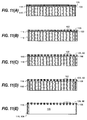
FIGS. 9(A)-(F) , another example embodiment of the method is shown. As above, inFIG. 9(A) , the reinforcingstructure material layer 116 is masked and etched on afirst side 118 to createopenings 120 in the reinforcingstructure material layer 116. Again, theseopenings 120 correspond to thefluid return channels 110. The material that is not etched away 122 corresponds to a portion the reinforcingstructure 108 inFIG. 5 . Theopenings 120 on thefirst side 118 of the reinforcingstructure material layer 116 can then be filled with asacrificial material layer 124. Subsequently, a planarization process such as a chemical mechanical polish (or CMP) is used to remove excess thickness of thesacrificial material layer 124 to bring it down to the same level as thefirst side 118 of the reinforcingstructure material layer 116, as shown inFIG. 9(B) . When theopenings 120 have been filled, the catcherface material layer 126 is provided via a deposition or a lamination process (not shown). The catcherface material layer 126 is masked using a photolithographic mask and the layer is etched, as shown inFIG. 9(C) , creating thepores 102 in the catcher face. InFIG. 9(D) , thesecond side 128 of the reinforcingstructure material layer 116 is masked using a third photolithographic mask and etched to createopenings 132 in the backside (or second side) 128 of the reinforcingstructure material layer 116. Theseopenings 132 are of a different cross-section than theopenings 120 etched in thefirst side 118 of the reinforcingstructure material layer 116. InFIG. 9(E) , a fourth photolithographic mask is used to again mask thesecond side 128 of the reinforcingstructure material layer 116 and it is again etched to form theliquid removal manifold 130. A material removal process is used to release thesacrificial material layer 124, fluidically connecting theopenings 132 and 120 (now fluid channels 110) in the reinforcing structure and thepores 102 of the catcher face (shown inFIG. 9(F) ). As above, the specific material removal process to be used depends on the particular material selected for the sacrificial material layer. - It is not necessary to etch the openings in the reinforcing structure material layer before applying the catcher face material layer, as is shown in the example embodiment described with reference to
FIGS. 10(A)-(D) . InFIG. 10(A) , the catcherface material layer 126 is provided on thefirst side 118 of the reinforcingstructure material layer 116 via a deposition or a lamination process. As previously stated, other processes can be used, provided that they sufficiently join the layers together, depending on the specific application contemplated. The catcherface material layer 126 is masked using a first photolithographic mask and the layer is etched, creating thepores 102 in the catcher face, as shown inFIG. 10(B) . Next, inFIG. 10(C) thesecond side 128 of the reinforcingstructure material layer 116 is masked using a second photolithographic mask and etched to createopenings 132 in the backside (or second side) 128 of the reinforcingstructure material layer 116. Theseopenings 132 define the locations of thefluid channels 110 of the reinforcing structure. Then, inFIG. 10(D) , an additional photolithographic mask is used to mask thesecond side 128 of the reinforcingstructure material layer 116 and thesecond side 128 of the reinforcingstructure material layer 116 is again etched to form theliquid return manifold 130. This final etching process additionally fluidically connects the openings in the reinforcing structure (now the fluid channels 110) and thepores 102 of the catcher face. - Furthermore, in some embodiments of the method, such as the example embodiment shown in
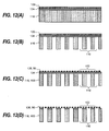
FIGS. 11(A)-11(E) , the catcher face material layer can be etched first, forming a mask for use in etching the reinforcing structure material layer. When this method is used, the catcherface material layer 126 applied to the reinforcingstructure material layer 108 by deposition or lamination as shown inFIG. 11 (A) . The reinforcing structure material layer is a thin flexible material layer, which provides the enhanced mechanical strength without adding too much flow resistance. Examples of flexible materials are metals such as tantalum or polymers such as polyimide or SU-8. InFIG. 11 (B) , a first photolithographic mask is applied and the catcherface material layer 126 is etched, creating thepores 102 in the catcher face. Upon completion of the first etching process, the etched catcher face material layer forms the mask for use during a second etching process to etch the fluid channels through the reinforcingstructure material layer 108 using an anisotropic etching process,FIG. 11 (C) , or an isotropic etching process (not shown). When an anisotropic etching process is used, the fluid channels have uniform cross section that is substantially the same as the pores in the catcher face layer. When an isotropic etch process is used, the difference in material properties of the layers will result in the openings in the reinforcing structure material layer (the fluid channels) being larger than the openings in the catcher face material layer (the pores). Due to the nature of isotropic etching, the cross section of the fluid channel varies through the thickness of the reinforcing structure material layer. Also, fluid channel cross section that is smaller than the thickness of the reinforcing structure material layer can not be created using the single isotropic etching process. Alternatively, a two step etching process can be used to etch the reinforcingstructure material layer 108 by an anisotropic etching process followed by an isotropic etching process. InFIG. 11(D) , an anisotropic etching process is used to etch through the reinforcingstructure material layer 108. Then inFIG. 11 (E) , an isotropic etching process is used to increase the cross section of the fluid channel etched through the reinforcingstructure material layer 108. The cross section of the fluid channel through the thickness of the reinforcing structure material layer is more uniform in the two step etching process than in the single isotropic etching process. Furthermore, a high aspect ratio fluid channel (cross section width smaller than the thickness of the reinforcing structure material layer) can be created using the two step etching process. - In some embodiments of the method, an etch stop is used for higher accuracy of the etching process. The etch stop is a material that is not etched by the etching process used to etch another material layer. For example when etching Silicon using the DRIE process, silicon dioxide or silicon nitride can be used as etch stops. Such etch stop materials can then be removed by using an etching process that doesn't attack the silicon. When an etch stop is used, the depth of etching will be controlled by the location or depth of the etch stop rather than by time alone.
- In the example embodiment shown in
FIGS. 12(A)-12(D) , the reinforcingstructure material layer 116 is in direct contact with the first surface of anetch stop layer 134. The second surface of theetch stop layer 134 is in direct contact with the catcherface material layer 126, as shown inFIG. 12(A) . Thus, where without an etch stop the etching can vary because of the variable thickness of the layer being etched, the etch stop ensures that the layer is etched to a uniform depth. Referring toFIG. 12(B) , the reinforcingstructure material layer 116 is masked using a photolithographic mask and then etched to theetch stop 134. The openings etched in the reinforcingstructure material layer 116 correspond to thefluid channels 110. Likewise, as shown inFIG. 12(C) , the catcherface material layer 126 is masked using a photolithographic mask and then etched to theetch stop 134. The openings etched in the catcherface material layer 126 correspond to thepores 102 in the catcher face. Finally, as shown inFIG. 12(D) , the photolithographic masks are removed from the surfaces of the catcherface material layer 126 and the reinforcingstructure material layer 116, and theetch stop 134 is removed to fluidically connect thepores 102 of the catcher face and the openings of the reinforcing structure (fluid channels) 110. The specific process necessary for removal of the etch stop layer depends on the particular material selected as an etch stop, and will be apparent to one skilled in the art. - The location of an etch stop layer is not limited to between the catcher face material layer and the reinforcing structure material layer, however. For example, as shown in
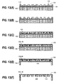
FIGS. 13(A)-(F) , theetch stop layer 134 can be located between the reinforcingstructure material layer 116 and asubstrate 136. The substrate can be, for example, silicon, though other materials can be used depending on the specific application contemplated. When theetch stop layer 134 is located between the reinforcingstructure material layer 116 and asubstrate 136, the openings in the reinforcing structure (which become the fluid channels 110) are created by masking the reinforcingstructure material layer 116 using a photolithographic mask and etching to theetch stop 134. This can be done in one step (not shown) or, as shown in the example embodiment shown inFIG. 13(A) , a first photolithographic mask can be applied and the reinforcingstructure material layer 116 can be etched for a specific period of time, but stopped before reaching theetch stop layer 134, creatingopenings 120 in the reinforcingstructure material layer 116. Then, as shown inFIG. 13(B) , another photolithographic mask is used, and the reinforcingstructure material layer 116 is etched to theetch stop layer 134. This two-step etching process creates openings 120 (and later fluid channels 110) with varying cross-sections over the length of the opening 120 (or fluid channel 110). Theopenings 120 of the reinforcingstructure material layer 116 are then filled with asacrificial material layer 124. Subsequently, a planarization process such as a chemical mechanical polish (or CMP) is used to remove excess thickness of thesacrificial material layer 124 to bring it down to the same level as thefirst side 118 of the reinforcingstructure material layer 116, as shown inFIG. 13(C) . When theopenings 120 have been filled, the catcherface material layer 126 can then be provided via a deposition or a lamination process. Other processes can be used, provided that they sufficiently join the layers together, depending on the specific application contemplated. As described in accordance with other embodiments above, the catcherface material layer 126 is masked using a photolithographic mask and the layer is etched to create thepores 102 in the catcher face (shown inFIG. 13(D) ). Additionally, thesubstrate 136 can be masked and etched to form, for example, aliquid removal manifold 130, as shown inFIG. 13(E) . Theetch stop layer 134 and thesacrificial material layer 124 are then removed, fluidically connecting thepores 102 of the catcher face, thefluid channels 110, and theliquid removal manifold 130. However, theliquid return manifold 130 need not be etched while it is attached to the reinforcing structure. For example, the liquid return manifold can be attached to a reinforcing structure/catcher face assembly after each has been already formed. - In the example embodiment shown in
FIGS. 14(A)-14(D) , the reinforcingstructure material layer 116 is in direct contact with the catcherface material layer 126. A reinforcingstructure material layer 116 is provided, as shown inFIG. 14(A) . An example of the reinforcingstructure material layer 116 is silicon. InFIG. 14(B) , reinforcingstructure material layer 116 is masked using a photolithographic mask and then etched through. For a silicon reinforcingstructure material layer 116, a DRIE etching process can be used to produce the high aspect ratio through the wafer openings. The openings etched in the reinforcingstructure material layer 116 correspond to thefluid channels 110. Referring toFIG. 14(C) , a thin dry film material such as polyimide or a dry photo imageable polymeric material is laminated or bonded to the reinforcingstructure material layer 116. Finally, as shown inFIG. 14(D) , the photolithographic mask is applied to etch thepores 102 of the catcher face in the catcherface material layer 126. The final etch fluidically connects thepores 102 of the catcher face and the openings of the reinforcing structure (fluid channels) 110. -
FIGS. 15(A)-15(E) shown example arrangements of the pores of the liquid drop contact structure. InFIG. 15(A) , the pores are long slots extend substantially parallel to the direction of the liquid drops. InFIG. 15(B) , the pores are long slots extend substantially perpendicular to the direction of the liquid drops. InFIG. 15(C) , the pores have square or rectangular shapes. InFIG. 15(D) , the pores are oval shaped. InFIG. 1 S(E), the pores are circles arranged in a square pattern. InFIG. 15(F) , the pores are circles arranged in a hexagonal pattern. Other pore shapes or patterns are possible. - The following example, corresponding to the manufacturing steps shown in
FIGS. 12(A) through 12(D) , provides an example embodiment of the manufacturing method of the present invention and is not inclusive of all possible embodiments of the invention. - A silicon-on-insulator ("SOI") wafer was selected having the following configuration: a silicon layer with a thickness of 25 µm ("catcher face material layer"), a silicon dioxide layer with a thickness of 1 µm ("etch stop material layer"), and a second silicon layer with a thickness of 350 µm ("reinforcing structure material layer"). The SOI wafer was oxidized to create a 2 µm layer of silicon dioxide on each of the catcher face material layer and the reinforcing structure material layer.
- The wafer was patterned through photolithography to define an etching pattern for the reinforcing structure material layer. RIE was used to etch the silicon dioxide on the reinforcing structure material layer to form the etching mask for the reinforcing structure material layer. DRIE was then used to etch the reinforcing structure material layer. The etching was stopped when it reached the etch stop material layer. This step creates the fluid channels in the reinforcing structure material layer.
- The wafer was also patterned through photolithography to define an etching pattern for the catcher face material layer. Reactive ion etching ("RIE") was used to etch the silicon dioxide on the catcher face material layer to form the etching mask for the catcher face material layer. Deep reactive ion etching ("DRIE") was then used to etch the catcher face material layer. The etching was stopped when it reached the etch stop material layer. This step creates the pores having a pore size of about 3 µm to about 5 µm in the catcher face material layer.
- RIE was used to etch away the exposed silicon dioxide. The RIE is a material removal process which removes the material in the etch stop material layer to mechanically couple the pores in the catcher face material layer to the fluid channels in the reinforcing structure material layer.
-
- 20
- continuous ink jet printer system
- 22
- image source
- 24
- image processing unit
- 26
- mechanism control circuits
- 28
- device
- 30
- printhead
- 32
- recording medium
- 34
- recording medium transport system
- 36
- recording medium transport control system
- 38
- micro-controller
- 40
- reservoir
- 42
- catcher
- 44
- recycling unit
- 46
- pressure regulator
- 47
- channel
- 48
- jetting module
- 49
- nozzle plate
- 50
- plurality of nozzles
- 51
- heater
- 52
- liquid
- 54
- drops
- 56
- drops
- 57
- trajectory
- 58
- drop stream
- 60
- gas flow deflection mechanism
- 61
- positive pressure gas flow structure
- 62
- gas
- 63
- negative pressure gas flow structure
- 64
- deflection zone
- 66
- small drop trajectory
- 68
- large drop trajectory
- 72
- first gas flow duct
- 74
- lower wall
- 76
- upper wall
- 78
- second gas flow duct
- 82
- upper wall
- 84
- seal
- 86
- liquid return duct
- 88
- plate
- 90
- front face
- 92
- positive pressure source
- 94
- negative pressure source
- 96
- wall
- 100
- liquid drop contact structure
- 102
- pores
- 104
- negative pressure source
- 106
- pressure regulator
- 108
- reinforcing structure
- 110
- fluid channels
- 111
- Non-porous Section
- 112
- Edge with radius
- 114
- additional vacuum source
- 116
- reinforcing structure material layer
- 118
- first side of reinforcing structure material layer
- 120
- openings in first side of reinforcing structure material layer
- 122
- material left by etch
- 124
- sacrificial material layer
- 126
- catcher face material layer
- 128
- second side of reinforcing structure material layer
- 130
- liquid removal manifold
- 132
- openings in second side of reinforcing structure material layer
- 134
- etch stop layer
- 136
- substrate
Claims (14)
- A printhead comprising:a catcher (42) including a liquid drop contact structure (100), the liquid drop contact structure including a plurality of pores (102), each of the plurality of pores having a substantially uniform size when compared to each other, the plurality of pores having a critical pressure point above which air can displace liquid from the plurality of pores; anda negative pressure source (94) in fluid communication with the plurality of pores of the liquid contact structure, the negative pressure source including a pressure regulator to control the negative pressure such that the negative pressure remains below the critical pressure point of the plurality of pores of the liquid drop contact structure.
- The printhead of claim 1, wherein the catcher further comprises a liquid return duct that is physically distinct from the plurality of pores of the liquid drop contact structure.
- The printhead of claim 2, wherein the catcher further comprises a negative pressure source in fluid communication with the liquid return duct.
- The printhead of claim 1, further comprising:a reinforcing structure in contact with the liquid drop contact structure, the reinforcing structure including a plurality of fluid channels through which liquid from the plurality of pores can be removed.
- The printhead of claim 4, wherein the plurality of fluid channels of the reinforcing structure includes openings that have lower fluid impedance when compared to the plurality of pores of the liquid drop contact structure.
- The printhead of claim 4, wherein the reinforcing structure includes a first layer having a first wall thickness and a second layer having a second wall thickness, the first wall thickness being different from the second wall thickness.
- The printhead of claim 4, the reinforcing structure being a first reinforcing structure located on a first side of the liquid drop contact structure, the catcher further comprising:a second reinforcing structure located on a second side of the liquid drop contact structure.
- The printhead of claim 1, wherein the plurality of pores are arranged in a two dimensional pattern.
- The printhead of claim 1, wherein the portion of the liquid drop contact structure including the plurality of pores is made from a hydrophilic material.
- The printhead of claim 1, the liquid drop contact structure being located a face of the catcher that also includes a non-porous section.
- The printhead of claim 1, further comprising:a source of liquid in liquid communication with the liquid drop contact structure to provide liquid to the plurality of pores.
- The printhead of claim 1, wherein the negative pressure provided by the negative pressure source is maintained at a substantially constant pressure level below the critical pressure point of the plurality of pores of the liquid drop contact structure.
- The printhead of claim 1, wherein the negative pressure provided by the negative pressure source varies in time within a pressure range below the critical pressure point of the plurality of pores of the liquid drop contact structure.
- A method of printing comprising:providing a catcher including a liquid drop contact structure, the liquid drop contact structure including a plurality of pores, each of the plurality of pores having a substantially uniform size when compared to each other, the plurality of pores having a critical pressure point above which air can displace liquid from the plurality of pores;providing a negative pressure source in fluid communication with the plurality of pores of the liquid contact structure;regulating the negative pressure using a pressure regulator such that the negative pressure remains below the critical pressure point of the plurality of pores of the liquid drop contact structure;ejecting liquid drops from a jetting module; andcausing some of the liquid droplets ejected from the jetting module to contact the liquid drop contact structure, the liquid droplets displacing air from the plurality of pores after contacting the liquid drop contact structure.
Applications Claiming Priority (2)
| Application Number | Priority Date | Filing Date | Title |
|---|---|---|---|
| US12/468,075 US7938522B2 (en) | 2009-05-19 | 2009-05-19 | Printhead with porous catcher |
| PCT/US2010/001441 WO2010134967A1 (en) | 2009-05-19 | 2010-05-14 | Printhead with porous catcher |
Publications (2)
| Publication Number | Publication Date |
|---|---|
| EP2432645A1 EP2432645A1 (en) | 2012-03-28 |
| EP2432645B1 true EP2432645B1 (en) | 2012-12-05 |
Family
ID=42556920
Family Applications (1)
| Application Number | Title | Priority Date | Filing Date |
|---|---|---|---|
| EP10724157A Not-in-force EP2432645B1 (en) | 2009-05-19 | 2010-05-14 | Printhead with porous catcher |
Country Status (5)
| Country | Link |
|---|---|
| US (1) | US7938522B2 (en) |
| EP (1) | EP2432645B1 (en) |
| JP (1) | JP2012527365A (en) |
| CN (1) | CN102427949B (en) |
| WO (1) | WO2010134967A1 (en) |
Families Citing this family (13)
| Publication number | Priority date | Publication date | Assignee | Title |
|---|---|---|---|---|
| US7946691B2 (en) * | 2008-11-05 | 2011-05-24 | Eastman Kodak Company | Deflection device including expansion and contraction regions |
| US9174438B2 (en) * | 2010-07-27 | 2015-11-03 | Eastman Kodak Company | Liquid film moving over porous catcher surface |
| WO2012014379A1 (en) * | 2010-07-28 | 2012-02-02 | Canon Kabushiki Kaisha | Liquid ejection head and liquid ejection apparatus |
| RU2593254C2 (en) | 2010-12-28 | 2016-08-10 | Стэмфорд Девайсиз Лтд. | Photodefined aperture plate and its manufacturing method |
| JP5744563B2 (en) * | 2011-02-25 | 2015-07-08 | キヤノン株式会社 | Liquid recovery apparatus, liquid recovery method, and liquid discharge apparatus |
| US8419175B2 (en) * | 2011-08-19 | 2013-04-16 | Eastman Kodak Company | Printing system including filter with uniform pores |
| BR112014027624B1 (en) * | 2012-06-11 | 2021-01-19 | Stamford Devices Ltd | method of making an aerosol forming orifice plate blade, orifice plate, aerosol forming device and orifice plate blade |
| US8714722B2 (en) * | 2012-07-20 | 2014-05-06 | Xerox Corporation | Multiple layer filter |
| US9653709B2 (en) * | 2012-11-20 | 2017-05-16 | The Regents Of The University Of Michigan | Optoelectronic device formed with controlled vapor flow |
| US8746863B1 (en) * | 2013-03-11 | 2014-06-10 | Eastman Kodak Company | Printhead including coanda catcher with grooved radius |
| US8857954B2 (en) | 2013-03-11 | 2014-10-14 | Eastman Kodak Company | Printhead including coanda catcher with grooved radius |
| WO2015177311A1 (en) | 2014-05-23 | 2015-11-26 | Stamford Devices Limited | A method for producing an aperture plate |
| US11448958B2 (en) * | 2017-09-21 | 2022-09-20 | Canon Kabushiki Kaisha | System and method for controlling the placement of fluid resist droplets |
Family Cites Families (21)
| Publication number | Priority date | Publication date | Assignee | Title |
|---|---|---|---|---|
| US3373437A (en) * | 1964-03-25 | 1968-03-12 | Richard G. Sweet | Fluid droplet recorder with a plurality of jets |
| JPS56120244U (en) * | 1980-02-18 | 1981-09-12 | ||
| US4520366A (en) * | 1984-01-09 | 1985-05-28 | The Mead Corporation | Method and apparatus for air start/stop of an ink jet printing device |
| US4667207A (en) * | 1986-06-13 | 1987-05-19 | Burlington Industries, Inc. | Ink jet system catcher structure |
| US4839664A (en) * | 1987-07-02 | 1989-06-13 | Burlington Industries, Inc. | Fluid-jet catcher with removable porous metal ingestion blade |
| JPH01165445A (en) * | 1987-12-22 | 1989-06-29 | Minolta Camera Co Ltd | Waste liquor recovering apparatus |
| GB9621525D0 (en) * | 1996-10-16 | 1996-12-04 | Domino Printing Sciences Plc | Liquid collection |
| US6454835B1 (en) * | 2000-06-02 | 2002-09-24 | Scitex Digital Printing, Inc. | Two-phase flow separator |
| US6554410B2 (en) * | 2000-12-28 | 2003-04-29 | Eastman Kodak Company | Printhead having gas flow ink droplet separation and method of diverging ink droplets |
| US6505921B2 (en) * | 2000-12-28 | 2003-01-14 | Eastman Kodak Company | Ink jet apparatus having amplified asymmetric heating drop deflection |
| US6588888B2 (en) * | 2000-12-28 | 2003-07-08 | Eastman Kodak Company | Continuous ink-jet printing method and apparatus |
| US6457807B1 (en) * | 2001-02-16 | 2002-10-01 | Eastman Kodak Company | Continuous ink jet printhead having two-dimensional nozzle array and method of redundant printing |
| US6491362B1 (en) * | 2001-07-20 | 2002-12-10 | Eastman Kodak Company | Continuous ink jet printing apparatus with improved drop placement |
| US6827429B2 (en) * | 2001-10-03 | 2004-12-07 | Eastman Kodak Company | Continuous ink jet printing method and apparatus with ink droplet velocity discrimination |
| US6851796B2 (en) * | 2001-10-31 | 2005-02-08 | Eastman Kodak Company | Continuous ink-jet printing apparatus having an improved droplet deflector and catcher |
| US6820970B2 (en) * | 2001-11-02 | 2004-11-23 | Eastman Kodak Company | Continuous ink jet catcher having delimiting edge and ink accumulation border |
| US6648461B2 (en) * | 2001-12-14 | 2003-11-18 | Eastman Kodak Company | Continuous ink jet catcher |
| US6592213B2 (en) * | 2001-12-14 | 2003-07-15 | Eastman Kodak Company | Continuous ink jet catcher |
| US6793328B2 (en) * | 2002-03-18 | 2004-09-21 | Eastman Kodak Company | Continuous ink jet printing apparatus with improved drop placement |
| US6575566B1 (en) * | 2002-09-18 | 2003-06-10 | Eastman Kodak Company | Continuous inkjet printhead with selectable printing volumes of ink |
| US6688736B1 (en) * | 2002-09-25 | 2004-02-10 | Scitex Digital Printing, Inc. | Wicking arrangement to eliminate catcher dripping |
-
2009
- 2009-05-19 US US12/468,075 patent/US7938522B2/en not_active Expired - Fee Related
-
2010
- 2010-05-14 JP JP2012511815A patent/JP2012527365A/en active Pending
- 2010-05-14 EP EP10724157A patent/EP2432645B1/en not_active Not-in-force
- 2010-05-14 WO PCT/US2010/001441 patent/WO2010134967A1/en active Application Filing
- 2010-05-14 CN CN201080022147.0A patent/CN102427949B/en not_active Expired - Fee Related
Also Published As
| Publication number | Publication date |
|---|---|
| WO2010134967A1 (en) | 2010-11-25 |
| EP2432645A1 (en) | 2012-03-28 |
| CN102427949B (en) | 2014-09-17 |
| US20100295910A1 (en) | 2010-11-25 |
| CN102427949A (en) | 2012-04-25 |
| JP2012527365A (en) | 2012-11-08 |
| US7938522B2 (en) | 2011-05-10 |
Similar Documents
| Publication | Publication Date | Title |
|---|---|---|
| EP2432645B1 (en) | Printhead with porous catcher | |
| EP2144761B1 (en) | An integral, micromachined gutter for inkjet printhead | |
| US7758155B2 (en) | Monolithic printhead with multiple rows of inkjet orifices | |
| US8534818B2 (en) | Printhead including particulate tolerant filter | |
| US20100295912A1 (en) | Porous catcher | |
| US20110261124A1 (en) | Printhead including filter associated with each nozzle | |
| US8490282B2 (en) | Method of manufacturing a porous catcher | |
| US20110012967A1 (en) | Catcher including drag reducing drop contact surface | |
| US8091992B2 (en) | Deflection device including gas flow restriction device | |
| US8398221B2 (en) | Printing using liquid film porous catcher surface | |
| US8562120B2 (en) | Continuous printhead including polymeric filter | |
| US8806751B2 (en) | Method of manufacturing printhead including polymeric filter | |
| US8398222B2 (en) | Printing using liquid film solid catcher surface | |
| US20110261126A1 (en) | Printhead including polymeric filter | |
| US9174438B2 (en) | Liquid film moving over porous catcher surface | |
| US8668313B2 (en) | Liquid ejection with on-chip deflection and collection | |
| US8668312B2 (en) | Liquid ejection with on-chip deflection and collection | |
| WO2012015675A1 (en) | Liquid film moving over solid catcher surface | |
| US8746863B1 (en) | Printhead including coanda catcher with grooved radius | |
| US8740366B1 (en) | Printhead including coanda catcher with grooved radius | |
| WO2012018498A1 (en) | Printing using liquid film porous catcher surface |
Legal Events
| Date | Code | Title | Description |
|---|---|---|---|
| PUAI | Public reference made under article 153(3) epc to a published international application that has entered the european phase |
Free format text: ORIGINAL CODE: 0009012 |
|
| 17P | Request for examination filed |
Effective date: 20111027 |
|
| AK | Designated contracting states |
Kind code of ref document: A1 Designated state(s): AL AT BE BG CH CY CZ DE DK EE ES FI FR GB GR HR HU IE IS IT LI LT LU LV MC MK MT NL NO PL PT RO SE SI SK SM TR |
|
| GRAP | Despatch of communication of intention to grant a patent |
Free format text: ORIGINAL CODE: EPIDOSNIGR1 |
|
| DAX | Request for extension of the european patent (deleted) | ||
| RIN1 | Information on inventor provided before grant (corrected) |
Inventor name: HSU, CHANG-FANG Inventor name: GUAN, SHAN Inventor name: YANG, QING Inventor name: XIE, YONGLIN |
|
| GRAS | Grant fee paid |
Free format text: ORIGINAL CODE: EPIDOSNIGR3 |
|
| GRAA | (expected) grant |
Free format text: ORIGINAL CODE: 0009210 |
|
| AK | Designated contracting states |
Kind code of ref document: B1 Designated state(s): AL AT BE BG CH CY CZ DE DK EE ES FI FR GB GR HR HU IE IS IT LI LT LU LV MC MK MT NL NO PL PT RO SE SI SK SM TR |
|
| REG | Reference to a national code |
Ref country code: GB Ref legal event code: FG4D |
|
| REG | Reference to a national code |
Ref country code: CH Ref legal event code: EP |
|
| REG | Reference to a national code |
Ref country code: AT Ref legal event code: REF Ref document number: 587044 Country of ref document: AT Kind code of ref document: T Effective date: 20121215 |
|
| REG | Reference to a national code |
Ref country code: IE Ref legal event code: FG4D |
|
| REG | Reference to a national code |
Ref country code: DE Ref legal event code: R096 Ref document number: 602010003991 Country of ref document: DE Effective date: 20130124 |
|
| REG | Reference to a national code |
Ref country code: NL Ref legal event code: T3 |
|
| REG | Reference to a national code |
Ref country code: AT Ref legal event code: MK05 Ref document number: 587044 Country of ref document: AT Kind code of ref document: T Effective date: 20121205 |
|
| PG25 | Lapsed in a contracting state [announced via postgrant information from national office to epo] |
Ref country code: FI Free format text: LAPSE BECAUSE OF FAILURE TO SUBMIT A TRANSLATION OF THE DESCRIPTION OR TO PAY THE FEE WITHIN THE PRESCRIBED TIME-LIMIT Effective date: 20121205 Ref country code: NO Free format text: LAPSE BECAUSE OF FAILURE TO SUBMIT A TRANSLATION OF THE DESCRIPTION OR TO PAY THE FEE WITHIN THE PRESCRIBED TIME-LIMIT Effective date: 20130305 Ref country code: LT Free format text: LAPSE BECAUSE OF FAILURE TO SUBMIT A TRANSLATION OF THE DESCRIPTION OR TO PAY THE FEE WITHIN THE PRESCRIBED TIME-LIMIT Effective date: 20121205 Ref country code: SE Free format text: LAPSE BECAUSE OF FAILURE TO SUBMIT A TRANSLATION OF THE DESCRIPTION OR TO PAY THE FEE WITHIN THE PRESCRIBED TIME-LIMIT Effective date: 20121205 Ref country code: ES Free format text: LAPSE BECAUSE OF FAILURE TO SUBMIT A TRANSLATION OF THE DESCRIPTION OR TO PAY THE FEE WITHIN THE PRESCRIBED TIME-LIMIT Effective date: 20130316 |
|
| REG | Reference to a national code |
Ref country code: LT Ref legal event code: MG4D |
|
| PG25 | Lapsed in a contracting state [announced via postgrant information from national office to epo] |
Ref country code: SI Free format text: LAPSE BECAUSE OF FAILURE TO SUBMIT A TRANSLATION OF THE DESCRIPTION OR TO PAY THE FEE WITHIN THE PRESCRIBED TIME-LIMIT Effective date: 20121205 Ref country code: PL Free format text: LAPSE BECAUSE OF FAILURE TO SUBMIT A TRANSLATION OF THE DESCRIPTION OR TO PAY THE FEE WITHIN THE PRESCRIBED TIME-LIMIT Effective date: 20121205 Ref country code: LV Free format text: LAPSE BECAUSE OF FAILURE TO SUBMIT A TRANSLATION OF THE DESCRIPTION OR TO PAY THE FEE WITHIN THE PRESCRIBED TIME-LIMIT Effective date: 20121205 Ref country code: GR Free format text: LAPSE BECAUSE OF FAILURE TO SUBMIT A TRANSLATION OF THE DESCRIPTION OR TO PAY THE FEE WITHIN THE PRESCRIBED TIME-LIMIT Effective date: 20130306 |
|
| PG25 | Lapsed in a contracting state [announced via postgrant information from national office to epo] |
Ref country code: AT Free format text: LAPSE BECAUSE OF FAILURE TO SUBMIT A TRANSLATION OF THE DESCRIPTION OR TO PAY THE FEE WITHIN THE PRESCRIBED TIME-LIMIT Effective date: 20121205 |
|
| PG25 | Lapsed in a contracting state [announced via postgrant information from national office to epo] |
Ref country code: IS Free format text: LAPSE BECAUSE OF FAILURE TO SUBMIT A TRANSLATION OF THE DESCRIPTION OR TO PAY THE FEE WITHIN THE PRESCRIBED TIME-LIMIT Effective date: 20130405 Ref country code: BG Free format text: LAPSE BECAUSE OF FAILURE TO SUBMIT A TRANSLATION OF THE DESCRIPTION OR TO PAY THE FEE WITHIN THE PRESCRIBED TIME-LIMIT Effective date: 20130305 Ref country code: BE Free format text: LAPSE BECAUSE OF FAILURE TO SUBMIT A TRANSLATION OF THE DESCRIPTION OR TO PAY THE FEE WITHIN THE PRESCRIBED TIME-LIMIT Effective date: 20121205 Ref country code: CZ Free format text: LAPSE BECAUSE OF FAILURE TO SUBMIT A TRANSLATION OF THE DESCRIPTION OR TO PAY THE FEE WITHIN THE PRESCRIBED TIME-LIMIT Effective date: 20121205 Ref country code: EE Free format text: LAPSE BECAUSE OF FAILURE TO SUBMIT A TRANSLATION OF THE DESCRIPTION OR TO PAY THE FEE WITHIN THE PRESCRIBED TIME-LIMIT Effective date: 20121205 Ref country code: SK Free format text: LAPSE BECAUSE OF FAILURE TO SUBMIT A TRANSLATION OF THE DESCRIPTION OR TO PAY THE FEE WITHIN THE PRESCRIBED TIME-LIMIT Effective date: 20121205 |
|
| PG25 | Lapsed in a contracting state [announced via postgrant information from national office to epo] |
Ref country code: PT Free format text: LAPSE BECAUSE OF FAILURE TO SUBMIT A TRANSLATION OF THE DESCRIPTION OR TO PAY THE FEE WITHIN THE PRESCRIBED TIME-LIMIT Effective date: 20130405 Ref country code: RO Free format text: LAPSE BECAUSE OF FAILURE TO SUBMIT A TRANSLATION OF THE DESCRIPTION OR TO PAY THE FEE WITHIN THE PRESCRIBED TIME-LIMIT Effective date: 20121205 |
|
| PLBE | No opposition filed within time limit |
Free format text: ORIGINAL CODE: 0009261 |
|
| STAA | Information on the status of an ep patent application or granted ep patent |
Free format text: STATUS: NO OPPOSITION FILED WITHIN TIME LIMIT |
|
| PG25 | Lapsed in a contracting state [announced via postgrant information from national office to epo] |
Ref country code: DK Free format text: LAPSE BECAUSE OF FAILURE TO SUBMIT A TRANSLATION OF THE DESCRIPTION OR TO PAY THE FEE WITHIN THE PRESCRIBED TIME-LIMIT Effective date: 20121205 |
|
| 26N | No opposition filed |
Effective date: 20130906 |
|
| PG25 | Lapsed in a contracting state [announced via postgrant information from national office to epo] |
Ref country code: CY Free format text: LAPSE BECAUSE OF FAILURE TO SUBMIT A TRANSLATION OF THE DESCRIPTION OR TO PAY THE FEE WITHIN THE PRESCRIBED TIME-LIMIT Effective date: 20121205 |
|
| PG25 | Lapsed in a contracting state [announced via postgrant information from national office to epo] |
Ref country code: MC Free format text: LAPSE BECAUSE OF FAILURE TO SUBMIT A TRANSLATION OF THE DESCRIPTION OR TO PAY THE FEE WITHIN THE PRESCRIBED TIME-LIMIT Effective date: 20121205 Ref country code: IT Free format text: LAPSE BECAUSE OF FAILURE TO SUBMIT A TRANSLATION OF THE DESCRIPTION OR TO PAY THE FEE WITHIN THE PRESCRIBED TIME-LIMIT Effective date: 20121205 |
|
| REG | Reference to a national code |
Ref country code: DE Ref legal event code: R097 Ref document number: 602010003991 Country of ref document: DE Effective date: 20130906 |
|
| PG25 | Lapsed in a contracting state [announced via postgrant information from national office to epo] |
Ref country code: HR Free format text: LAPSE BECAUSE OF FAILURE TO SUBMIT A TRANSLATION OF THE DESCRIPTION OR TO PAY THE FEE WITHIN THE PRESCRIBED TIME-LIMIT Effective date: 20130731 |
|
| REG | Reference to a national code |
Ref country code: IE Ref legal event code: MM4A |
|
| REG | Reference to a national code |
Ref country code: FR Ref legal event code: ST Effective date: 20140131 |
|
| PG25 | Lapsed in a contracting state [announced via postgrant information from national office to epo] |
Ref country code: IE Free format text: LAPSE BECAUSE OF NON-PAYMENT OF DUE FEES Effective date: 20130514 |
|
| PG25 | Lapsed in a contracting state [announced via postgrant information from national office to epo] |
Ref country code: FR Free format text: LAPSE BECAUSE OF NON-PAYMENT OF DUE FEES Effective date: 20130531 |
|
| REG | Reference to a national code |
Ref country code: CH Ref legal event code: PL |
|
| GBPC | Gb: european patent ceased through non-payment of renewal fee |
Effective date: 20140514 |
|
| PG25 | Lapsed in a contracting state [announced via postgrant information from national office to epo] |
Ref country code: LI Free format text: LAPSE BECAUSE OF NON-PAYMENT OF DUE FEES Effective date: 20140531 Ref country code: CH Free format text: LAPSE BECAUSE OF NON-PAYMENT OF DUE FEES Effective date: 20140531 |
|
| PG25 | Lapsed in a contracting state [announced via postgrant information from national office to epo] |
Ref country code: MT Free format text: LAPSE BECAUSE OF FAILURE TO SUBMIT A TRANSLATION OF THE DESCRIPTION OR TO PAY THE FEE WITHIN THE PRESCRIBED TIME-LIMIT Effective date: 20121205 |
|
| PG25 | Lapsed in a contracting state [announced via postgrant information from national office to epo] |
Ref country code: GB Free format text: LAPSE BECAUSE OF NON-PAYMENT OF DUE FEES Effective date: 20140514 Ref country code: SM Free format text: LAPSE BECAUSE OF FAILURE TO SUBMIT A TRANSLATION OF THE DESCRIPTION OR TO PAY THE FEE WITHIN THE PRESCRIBED TIME-LIMIT Effective date: 20121205 |
|
| PG25 | Lapsed in a contracting state [announced via postgrant information from national office to epo] |
Ref country code: TR Free format text: LAPSE BECAUSE OF FAILURE TO SUBMIT A TRANSLATION OF THE DESCRIPTION OR TO PAY THE FEE WITHIN THE PRESCRIBED TIME-LIMIT Effective date: 20121205 |
|
| PG25 | Lapsed in a contracting state [announced via postgrant information from national office to epo] |
Ref country code: HU Free format text: LAPSE BECAUSE OF FAILURE TO SUBMIT A TRANSLATION OF THE DESCRIPTION OR TO PAY THE FEE WITHIN THE PRESCRIBED TIME-LIMIT; INVALID AB INITIO Effective date: 20100514 Ref country code: MK Free format text: LAPSE BECAUSE OF FAILURE TO SUBMIT A TRANSLATION OF THE DESCRIPTION OR TO PAY THE FEE WITHIN THE PRESCRIBED TIME-LIMIT Effective date: 20121205 Ref country code: LU Free format text: LAPSE BECAUSE OF NON-PAYMENT OF DUE FEES Effective date: 20130514 |
|
| PGFP | Annual fee paid to national office [announced via postgrant information from national office to epo] |
Ref country code: NL Payment date: 20170510 Year of fee payment: 8 |
|
| PGFP | Annual fee paid to national office [announced via postgrant information from national office to epo] |
Ref country code: DE Payment date: 20170531 Year of fee payment: 8 |
|
| PG25 | Lapsed in a contracting state [announced via postgrant information from national office to epo] |
Ref country code: AL Free format text: LAPSE BECAUSE OF FAILURE TO SUBMIT A TRANSLATION OF THE DESCRIPTION OR TO PAY THE FEE WITHIN THE PRESCRIBED TIME-LIMIT Effective date: 20121205 |
|
| REG | Reference to a national code |
Ref country code: DE Ref legal event code: R119 Ref document number: 602010003991 Country of ref document: DE |
|
| REG | Reference to a national code |
Ref country code: NL Ref legal event code: MM Effective date: 20180601 |
|
| PG25 | Lapsed in a contracting state [announced via postgrant information from national office to epo] |
Ref country code: DE Free format text: LAPSE BECAUSE OF NON-PAYMENT OF DUE FEES Effective date: 20181201 Ref country code: NL Free format text: LAPSE BECAUSE OF NON-PAYMENT OF DUE FEES Effective date: 20180601 |