EP2432642B1 - Remote ink supply - Google Patents
Remote ink supply Download PDFInfo
- Publication number
- EP2432642B1 EP2432642B1 EP09845019.0A EP09845019A EP2432642B1 EP 2432642 B1 EP2432642 B1 EP 2432642B1 EP 09845019 A EP09845019 A EP 09845019A EP 2432642 B1 EP2432642 B1 EP 2432642B1
- Authority
- EP
- European Patent Office
- Prior art keywords
- ink
- printer
- pump
- flexible
- printing system
- Prior art date
- Legal status (The legal status is an assumption and is not a legal conclusion. Google has not performed a legal analysis and makes no representation as to the accuracy of the status listed.)
- Active
Links
Images


Classifications
-
- B—PERFORMING OPERATIONS; TRANSPORTING
- B41—PRINTING; LINING MACHINES; TYPEWRITERS; STAMPS
- B41J—TYPEWRITERS; SELECTIVE PRINTING MECHANISMS, i.e. MECHANISMS PRINTING OTHERWISE THAN FROM A FORME; CORRECTION OF TYPOGRAPHICAL ERRORS
- B41J2/00—Typewriters or selective printing mechanisms characterised by the printing or marking process for which they are designed
- B41J2/005—Typewriters or selective printing mechanisms characterised by the printing or marking process for which they are designed characterised by bringing liquid or particles selectively into contact with a printing material
- B41J2/01—Ink jet
- B41J2/17—Ink jet characterised by ink handling
- B41J2/175—Ink supply systems ; Circuit parts therefor
- B41J2/17503—Ink cartridges
- B41J2/17506—Refilling of the cartridge
- B41J2/17509—Whilst mounted in the printer
-
- B—PERFORMING OPERATIONS; TRANSPORTING
- B41—PRINTING; LINING MACHINES; TYPEWRITERS; STAMPS
- B41J—TYPEWRITERS; SELECTIVE PRINTING MECHANISMS, i.e. MECHANISMS PRINTING OTHERWISE THAN FROM A FORME; CORRECTION OF TYPOGRAPHICAL ERRORS
- B41J2/00—Typewriters or selective printing mechanisms characterised by the printing or marking process for which they are designed
- B41J2/005—Typewriters or selective printing mechanisms characterised by the printing or marking process for which they are designed characterised by bringing liquid or particles selectively into contact with a printing material
- B41J2/01—Ink jet
- B41J2/17—Ink jet characterised by ink handling
- B41J2/175—Ink supply systems ; Circuit parts therefor
-
- B—PERFORMING OPERATIONS; TRANSPORTING
- B41—PRINTING; LINING MACHINES; TYPEWRITERS; STAMPS
- B41J—TYPEWRITERS; SELECTIVE PRINTING MECHANISMS, i.e. MECHANISMS PRINTING OTHERWISE THAN FROM A FORME; CORRECTION OF TYPOGRAPHICAL ERRORS
- B41J2/00—Typewriters or selective printing mechanisms characterised by the printing or marking process for which they are designed
- B41J2/005—Typewriters or selective printing mechanisms characterised by the printing or marking process for which they are designed characterised by bringing liquid or particles selectively into contact with a printing material
- B41J2/01—Ink jet
- B41J2/17—Ink jet characterised by ink handling
- B41J2/175—Ink supply systems ; Circuit parts therefor
- B41J2/17596—Ink pumps, ink valves
Definitions
- Inkjet printers utilize liquid ink to form images on media. Such printers typically use numerous colors of ink in order to provide color saturation and resolution in accordance with the expectations of the user. Traditionally, such inks are supplied to a printer by way of replaceable cartridges that are supported substantially or entirely within the housing of the printer.
- EP 0 778 146 A1 describes a printing system, comprising a printer including a printhead and an ink supply configured to be connected to the printer.
- the ink supply includes an ink reservoir, a pump and a fluid outlet which are housed in a common chassis.
- the ink supply is inserted into a docking bay of the printer and, upon insertion of the ink supply, an actuator within the docking bay is brought into contact with the pump through an aperture.
- the present invention provides a printing system according to claim 1 and a method according to claim 12. Embodiments of the invention are defined in the dependent claims.
- Connecting heads are mechanically engaged to respective ink cartridge receiving ports of the printer.
- Each connecting head includes a pump that is mechanically powered by an actuator of the printer.
- Each pump serves to drive the flow of an ink from one of the remote sources through connecting conduits to a printhead of the printer.
- Check valves prevent the backflow of ink from the printer to corresponding remote sources. Failure of a particular pump is detected by a sensor of the printer and interpreted as an out-of-ink condition.
- One or more alert messages and/or indications are provided to a user in response to the out-of-ink detection.
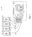
- FIG. 1 depicts a schematic view of a printing system 100.
- the system 100 is illustrative and non-limiting with respect to the present teachings. Thus, other systems can be configured and/or operated in accordance with the present teachings.
- the system 100 includes a printer 102.
- the printer 102 includes a controller 104 configured to control various normal operations of the printer 102.
- the controller 104 can be defined by any suitable controller, and can include one or more processors, one or more microcontrollers, application-specific integrated circuitry, state machine logic, analog and/or digital circuits, etc.
- processors one or more microcontrollers
- application-specific integrated circuitry one or more microcontrollers
- state machine logic analog and/or digital circuits, etc.
- One having ordinary skill in the printing and related arts can appreciate that the controller 104 can be various defined and configured, and that further elaboration is not required for purposes of understanding the present teachings.
- the printer 102 also includes a printhead 106 having a pressure regulator 108.
- the printhead 106 includes a plurality of ink ejection nozzles configured to apply liquid ink to a media 110 under the control of controller 104.
- the printhead 106 has one or more pressure regulators 108 which are configured to receive a respective color of liquid ink by way of flexible conduits 112 and to regulate the pressure of that color of ink as it is provided to the respective ink ejection nozzles of the printhead 106.
- the printer 102 further includes a plurality of actuators 114 positioned along a receiving bay 116.
- Each of the actuators 114 is configured to provide force pulses to a respective ink pump under the influence of the controller 104.
- the actuators 114 can be defined by any suitable mechanical device configured to provide a controllable force pulse.
- each actuator 114 is a mechanically-actuated piston. Other embodiments can also be used. Further elaboration regarding the operation of the actuators 114 is provided hereinafter.
- the receiving bay 116 defines a number of ink cartridge receiving ports 118.
- the printing system 100 also includes a plurality of ink supplies 120 through 126, inclusive.
- Each ink supply 120-126 includes a respective flexible walled ink bag (or sack) 128.
- each flexible bag 128 is configured to contain a quantity of liquid ink of a respective color.
- each flexible bag 128 is formed from a multi-layer layer material which may include nylon, silver, aluminum, linear low density polyethylene or other materials chosen for strength, compliance and low permeability. See, for non-limiting example, U.S. Patent No. 6,158,853 or U.S. Patent Application Publication No. 20060017788 A1 . Other materials can also be used.
- each flexible bag 128 is configured to decrease in internal volume as the ink within is drawn away and consumed, resulting in a vacuum backpressure within the respective flexible bag 128.
- Each flexible bag 128 further includes a septum 130 that is configured to seal the flexible bag 128 against leaking or other loss of the ink inside.
- each septum 130 can also be referred to as a self-sealing septum 130.
- Each septum 130 can be formed from polyisoprene, EPDM, combinations thereof, or another suitable flexible material.
- Each septum 130 is further configured to be penetrated (opened) by way of hollow needle 132 inserted there through.
- Each hollow needle 132 is fluidly coupled to a flexible conduit 134. In this way, the ink within a particular flexible bag 128 can be fluidly coupled to the printer 102 by way of a hollow needle 132 and a flexible conduit 134.
- the printing system 100 also includes a plurality of connecting heads 136.
- Each connecting head 136 includes a check valve 138 and a pump (see FIG. 2 ), and is configured to be selectively coupled and uncoupled (i.e., mechanically engaged and disengaged) from a respective one of the ink cartridge receiving ports 118.
- each of the connecting heads 136 is coupled to a one of the ink supplies 120-126 by way of a respective flexible conduit 134.
- the check valves 138 are configured to prevent ink from flowing back into the respective flexible bags 128.
- the printing system 100 is configured such that ink flows in one direction only - from the ink supplies 120-126 to the printer 102 by way of the conduits 134 and the connecting heads 136.
- the connecting head 136 includes a pump 200.
- the pump 200 includes a flexible diaphragm 202.
- the diaphragm 202 is generally dome (or convex) shaped and formed from any suitable flexible material such as EPDM, butyl, EPDM/butyl blends, etc. Other materials can also be used.
- the flexible diaphragm 202 is disposed adjacent to a pump chamber (or cavity) 204 defined by the material of the connecting head 136. As depicted in FIG. 2 , the flexible diaphragm 202 is in a distended state or condition, and is urged into such a distended state by way of a spring 206.
- the connecting head 136 also includes the check valve 138, which is defined by a flexible gate or disk 208.
- the flexible gate 208 can be formed from silicone or another suitable material.
- the flexible gate 208 is configured to seal off an inlet passageway 210 to the pump chamber 204 when the flexible diaphragm 202 is being acted upon by an outside force (i.e., actuator 114).
- the check valve 138 prevents the flow of ink from the pump chamber 204 back through the inlet passageway 210 during normal operations of the pump 200.
- the flow of ink within the connecting head 136 is a one-way operation: through the inlet passageway 210 and into the pump chamber 204.
- the actuator 114 applies a force pulse against the flexible diaphragm 202 under influence of the controller 104.
- the flexible diaphragm 202 transitions from a distended state to a collapsed state under the force of the actuator 114, thus reducing the internal volume of the pump chamber 204.
- Ink flows out of the pump chamber 204 through an outlet passageway 212 and into a fluid conduit 112 that couples the ink to a printhead (e.g., 106).
- the check valve 138 serves to prevent ink from flowing out of the pump chamber 204 by way of the inlet passageway 210.
- the force pulse from actuator 114 is ended (under automatic control).
- the internal volume of the pump chamber 204 is at a minimum, and the flow of ink ceases.
- the spring 206 operates to urge (i.e., push or bias) the flexible diaphragm 202 back toward the original distended state.
- the internal volume of the pump chamber 204 increases.
- the increasing volume of the pump chamber 204 serves to draws ink from the fluid conduit 134 through the inlet passageway 210 and the check valve 138, thus refilling the pump chamber 204.
- the ultimate source of the ink is the corresponding ink bag 128 as depicted in FIG. 1 .
- the pressure regulator 108 of the printhead 106 may include a check valve mechanism (not shown) that prevents the pump 200 from simply drawing the just-displaced ink back from the printhead.
- the ink delivery system is typically designed with fluidic impedances that assure that liquid is preferentially drawn from the bag 128 instead of the printhead 106. One pumping cycle is now complete.
- a sensor 214 is defined by an optical (light-beam) device that operates by way of a beam of light projected from an emitter across a span toward a detector.
- Normal operations of the pump 200 are detected as interruptions and restorations of the light beam while the actuator 114 reciprocates with the flexible diaphragm 202.
- a corresponding signal is provided to the controller 104 as confirmation of normal ink pumping operations.
- the pump 200 When the ink within the associated flexible bag 128 is depleted, a vacuum backpressure is communicated to the pump 200.
- the flexible diaphragm 202 cannot reciprocate and so remains in its collapsed state. As such, the pump 200 fails to operate.
- the actuator 114 When the actuator 114 is actuated, it immediately translates through its full stroke, stopping when it contacts the diaphragm in its collapsed state. This behavior is detected by the sensor 214.
- the sensor 214 provides a corresponding signal that is interpreted by the controller 104 as an out-of-ink condition.
- the controller 104 then halts normal printing operations and provides one or more user notifications that the out-of-ink issue must be addressed by way of, for non-limiting example, indicating lights, e-mail messaging, etc.
- FIG. 2 is typical of each color of ink used by the particular printer 102.
- the printer 102 is understood to consume four colors of ink as described above.
- a total of four connecting heads 136 - each having a pump 200 and a check valve 138 and being driven by an actuator 114 - would be used.
- Other printing systems having other numbers of connecting heads, pumps, check valves, actuators, sensors, etc., can also be configured and used in accordance with the present teachings.
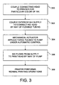
- FIG. 3 is a flow diagram depicting a method according to one embodiment of the invention.
- the method of FIG. 3 includes particular operations and order of execution. However, other methods including other operations, omitting one or more of the depicted operations, and/or proceeding in other orders of execution can also be used according to the present teachings. Thus, the method of FIG. 3 is illustrative and non-limiting in nature.
- a connecting head is manually coupled to an ink cartridge receiving port of an inkjet printer.
- the connecting head corresponds to a particular color of ink used by the printer (e.g., black, etc.).
- a connecting head 136 is coupled to a printer 102 by way of an ink cartridge receiving port 118. In so doing, the connecting head 136 is also mated in fluid communication with a conduit 112 within the printer 102.
- the connecting head is coupled to a supply of ink by way of a flexible liquid conduit (or tubing).
- the supply of ink is generally located remote from the printer.
- the connecting head 136 is coupled to a supply 120 having a flexible bag 128 by way of a hollow needle 132 and a fluid conduit 134.
- the connecting head 136 is fluidly coupled to a remote supply of ink and is mechanically engaged in fluid communication with the printer 102.
- a mechanical actuator of the printer applies one or more force pulses to a pump of the connecting head under automatic control.
- an actuator 114 applies a series of force pulses to the flexible diaphragm 202 of the connecting head 136 in accordance with control signals from the controller 104.
- black ink flows from the flexible bag 128 though the conduit 134, into and out of the pump 200, through the internal conduit 112 and to the pressure regulator 108 of the printhead 106.
- Such ink flow is maintained until ceased under automatic operation of the controller 104.
- the printer performs normal printing operations on media using the ink supplied from the remote supply (or source).
- the remote supply or source
- text, images, etc. are formed on sheet media 110 by the printhead 106 using the ink provided by way of the connecting head 136.
- imaging normal print operations
- signals provided by the controller 104 are provided by the controller 104.
- a remote supply of ink (with respect to a printer) is used for normal printing operations by way of a connecting head and its internal resources.
- a relatively large quantity of ink can be supplied to a printer so as to proportionately increasing the time between replenishments relative to the use of ink cartridges that are supported (housed) substantially within the printer.
- Numerous other methods consistent with the operations and/or objectives of the present teachings can also be used.
- FIG. 4 is a flow diagram depicting a method according to one embodiment of the invention.
- the method of FIG. 4 includes particular operations and order of execution. However, other methods including other operations, omitting one or more of the depicted operations, and/or proceeding in other orders of execution can also be used according to the present teachings. Thus, the method of FIG. 4 is illustrative and non-limiting in nature.
- a printer performs normal printing operations by application of one or more colors of ink onto sheet media.
- the printer 102 is forming images on sheet media 110 in accordance with controller 104 signaling.
- a flexible bag supplying ink to the printer runs out of ink, resulting in an internal vacuum backpressure communicated to the printer.
- the flexible bag 128 of the supply 124 is depleted of magenta ink, resulting in a vacuum backpressure being communicated to the corresponding pump 200.
- the flexible diaphragm of the pump coupled to the depleted supply cannot reciprocate due to the vacuum backpressure.
- the flexible diaphragm 202 of the corresponding pump 200 is in an essentially motionless state, and cannot reciprocate despite force pulses applied by the actuator 114 and/or the urging of the spring 206.
- the motionless state of the pump is detected by the corresponding sensor.
- the sensor 214 detects the substantially motionless state of the diaphragm 202.
- the sensor signal indicating the motionless condition of the diaphragm is communicated to the controller and is interpreted as an out-of-ink condition.
- the sensor 214 signal sent to the controller 104 results in a user notification of the out-of-ink condition and/or halting of normal printing operations.
Landscapes
- Ink Jet (AREA)
- Accessory Devices And Overall Control Thereof (AREA)
Abstract
Description
- Inkjet printers utilize liquid ink to form images on media. Such printers typically use numerous colors of ink in order to provide color saturation and resolution in accordance with the expectations of the user. Traditionally, such inks are supplied to a printer by way of replaceable cartridges that are supported substantially or entirely within the housing of the printer.
- However, users are often dissatisfied with the limited volume of ink that such cartridges provide, resulting in undesirably frequent replacement. The present teachings address the foregoing and other concerns.
-
EP 0 778 146 A1 describes a printing system, comprising a printer including a printhead and an ink supply configured to be connected to the printer. The ink supply includes an ink reservoir, a pump and a fluid outlet which are housed in a common chassis. The ink supply is inserted into a docking bay of the printer and, upon insertion of the ink supply, an actuator within the docking bay is brought into contact with the pump through an aperture.
The present invention provides a printing system according to claim 1 and a method according to claim 12. Embodiments of the invention are defined in the dependent claims. - The present embodiments will now be described, by way of example, with reference to the accompanying drawings, in which:
-
FIG. 1 depicts a schematic diagram of a printing system according to one embodiment; -
FIG. 2 depicts a schematic diagram of selected details of the printing system ofFIG. 1 ; -
FIG. 3 depicts a flow diagram of a method according to another embodiment. -
FIG. 4 depicts a flow diagram of a method according to yet another embodiment. - Means and methods for providing ink from one or more remote sources to a printer are provided by the present teachings. Connecting heads are mechanically engaged to respective ink cartridge receiving ports of the printer. Each connecting head includes a pump that is mechanically powered by an actuator of the printer. Each pump serves to drive the flow of an ink from one of the remote sources through connecting conduits to a printhead of the printer. Check valves prevent the backflow of ink from the printer to corresponding remote sources. Failure of a particular pump is detected by a sensor of the printer and interpreted as an out-of-ink condition. One or more alert messages and/or indications are provided to a user in response to the out-of-ink detection.
- The embodiments of the invention are defined in the appended claims.
- Reference is now directed to
FIG. 1 , which depicts a schematic view of aprinting system 100. Thesystem 100 is illustrative and non-limiting with respect to the present teachings. Thus, other systems can be configured and/or operated in accordance with the present teachings. - The
system 100 includes aprinter 102. Theprinter 102 includes acontroller 104 configured to control various normal operations of theprinter 102. Thecontroller 104 can be defined by any suitable controller, and can include one or more processors, one or more microcontrollers, application-specific integrated circuitry, state machine logic, analog and/or digital circuits, etc. One having ordinary skill in the printing and related arts can appreciate that thecontroller 104 can be various defined and configured, and that further elaboration is not required for purposes of understanding the present teachings. - The
printer 102 also includes aprinthead 106 having apressure regulator 108. Theprinthead 106 includes a plurality of ink ejection nozzles configured to apply liquid ink to amedia 110 under the control ofcontroller 104. Theprinthead 106 has one ormore pressure regulators 108 which are configured to receive a respective color of liquid ink by way offlexible conduits 112 and to regulate the pressure of that color of ink as it is provided to the respective ink ejection nozzles of theprinthead 106. - The
printer 102 further includes a plurality ofactuators 114 positioned along a receivingbay 116. Each of theactuators 114 is configured to provide force pulses to a respective ink pump under the influence of thecontroller 104. Theactuators 114 can be defined by any suitable mechanical device configured to provide a controllable force pulse. In one embodiment, eachactuator 114 is a mechanically-actuated piston. Other embodiments can also be used. Further elaboration regarding the operation of theactuators 114 is provided hereinafter. Thereceiving bay 116 defines a number of inkcartridge receiving ports 118. - The
printing system 100 also includes a plurality ofink supplies 120 through 126, inclusive. Each ink supply 120-126 includes a respective flexible walled ink bag (or sack) 128. In turn, eachflexible bag 128 is configured to contain a quantity of liquid ink of a respective color. In one embodiment, eachflexible bag 128 is formed from a multi-layer layer material which may include nylon, silver, aluminum, linear low density polyethylene or other materials chosen for strength, compliance and low permeability. See, for non-limiting example,U.S. Patent No. 6,158,853 orU.S. Patent Application Publication No. 20060017788 A1 . Other materials can also be used. As depicted, thesystem 100 includes four colors of ink (e.g., black, cyan, magenta and yellow). Other systems including other numbers and/or colors of ink are also contemplated by the present teachings. Additionally, eachflexible bag 128 is configured to decrease in internal volume as the ink within is drawn away and consumed, resulting in a vacuum backpressure within the respectiveflexible bag 128. - Each
flexible bag 128 further includes aseptum 130 that is configured to seal theflexible bag 128 against leaking or other loss of the ink inside. Thus, eachseptum 130 can also be referred to as a self-sealingseptum 130. Eachseptum 130 can be formed from polyisoprene, EPDM, combinations thereof, or another suitable flexible material. Eachseptum 130 is further configured to be penetrated (opened) by way ofhollow needle 132 inserted there through. Eachhollow needle 132 is fluidly coupled to aflexible conduit 134. In this way, the ink within a particularflexible bag 128 can be fluidly coupled to theprinter 102 by way of ahollow needle 132 and aflexible conduit 134. - The
printing system 100 also includes a plurality of connectingheads 136. Each connectinghead 136 includes acheck valve 138 and a pump (seeFIG. 2 ), and is configured to be selectively coupled and uncoupled (i.e., mechanically engaged and disengaged) from a respective one of the inkcartridge receiving ports 118. Additionally, each of the connectingheads 136 is coupled to a one of the ink supplies 120-126 by way of a respectiveflexible conduit 134. Thecheck valves 138 are configured to prevent ink from flowing back into the respectiveflexible bags 128. Thus, theprinting system 100 is configured such that ink flows in one direction only - from the ink supplies 120-126 to theprinter 102 by way of theconduits 134 and theconnecting heads 136. - Attention is now directed to
FIG. 2 , which depicts selected details of theprinting system 100. As introduced above, the connectinghead 136 includes apump 200. Thepump 200 includes aflexible diaphragm 202. Thediaphragm 202 is generally dome (or convex) shaped and formed from any suitable flexible material such as EPDM, butyl, EPDM/butyl blends, etc. Other materials can also be used. Theflexible diaphragm 202 is disposed adjacent to a pump chamber (or cavity) 204 defined by the material of the connectinghead 136. As depicted inFIG. 2 , theflexible diaphragm 202 is in a distended state or condition, and is urged into such a distended state by way of aspring 206. - The connecting
head 136 also includes thecheck valve 138, which is defined by a flexible gate ordisk 208. Theflexible gate 208 can be formed from silicone or another suitable material. Theflexible gate 208 is configured to seal off aninlet passageway 210 to thepump chamber 204 when theflexible diaphragm 202 is being acted upon by an outside force (i.e., actuator 114). In this way, thecheck valve 138 prevents the flow of ink from thepump chamber 204 back through theinlet passageway 210 during normal operations of thepump 200. Thus, the flow of ink within the connectinghead 136 is a one-way operation: through theinlet passageway 210 and into thepump chamber 204. - Still referring to
FIG. 2 , normal operations proceed as follows: theactuator 114 applies a force pulse against theflexible diaphragm 202 under influence of thecontroller 104. Theflexible diaphragm 202 transitions from a distended state to a collapsed state under the force of theactuator 114, thus reducing the internal volume of thepump chamber 204. Ink flows out of thepump chamber 204 through anoutlet passageway 212 and into afluid conduit 112 that couples the ink to a printhead (e.g., 106). Thecheck valve 138 serves to prevent ink from flowing out of thepump chamber 204 by way of theinlet passageway 210. - Once the
flexible diaphragm 202 has achieved the collapsed state, the force pulse fromactuator 114 is ended (under automatic control). At this point in the operation, the internal volume of thepump chamber 204 is at a minimum, and the flow of ink ceases. Thereafter, thespring 206 operates to urge (i.e., push or bias) theflexible diaphragm 202 back toward the original distended state. As theflexible diaphragm 202 transitions from the collapsed to the distended condition, the internal volume of thepump chamber 204 increases. The increasing volume of thepump chamber 204 serves to draws ink from thefluid conduit 134 through theinlet passageway 210 and thecheck valve 138, thus refilling thepump chamber 204. Of course, the ultimate source of the ink is thecorresponding ink bag 128 as depicted inFIG. 1 . Thepressure regulator 108 of theprinthead 106 may include a check valve mechanism (not shown) that prevents thepump 200 from simply drawing the just-displaced ink back from the printhead. The ink delivery system is typically designed with fluidic impedances that assure that liquid is preferentially drawn from thebag 128 instead of theprinthead 106. One pumping cycle is now complete. - The pumping process described above is now repeated continuously or from time-to-time, as required, under automatic control of the
controller 104 such that ink is provided to theprinthead 106 as needed to sustain normal printing operations. Thus, normal operation of thepump 200 can be described as reciprocations of theflexible diaphragm 202 between the distended condition and the collapsed condition. - These reciprocations, indicative of typical ink-moving operations of the
pump 200, are detected by asensor 214. In one embodiment, thesensor 214 is defined by an optical (light-beam) device that operates by way of a beam of light projected from an emitter across a span toward a detector. Normal operations of thepump 200 are detected as interruptions and restorations of the light beam while theactuator 114 reciprocates with theflexible diaphragm 202. A corresponding signal is provided to thecontroller 104 as confirmation of normal ink pumping operations. - When the ink within the associated
flexible bag 128 is depleted, a vacuum backpressure is communicated to thepump 200. Theflexible diaphragm 202 cannot reciprocate and so remains in its collapsed state. As such, thepump 200 fails to operate. When theactuator 114 is actuated, it immediately translates through its full stroke, stopping when it contacts the diaphragm in its collapsed state. This behavior is detected by thesensor 214. As a result, thesensor 214 provides a corresponding signal that is interpreted by thecontroller 104 as an out-of-ink condition. Thecontroller 104 then halts normal printing operations and provides one or more user notifications that the out-of-ink issue must be addressed by way of, for non-limiting example, indicating lights, e-mail messaging, etc. - It is important to note that
FIG. 2 is typical of each color of ink used by theparticular printer 102. For purposes of illustration, theprinter 102 is understood to consume four colors of ink as described above. Thus, a total of four connecting heads 136 - each having apump 200 and acheck valve 138 and being driven by an actuator 114 - would be used. Other printing systems having other numbers of connecting heads, pumps, check valves, actuators, sensors, etc., can also be configured and used in accordance with the present teachings. -
FIG. 3 is a flow diagram depicting a method according to one embodiment of the invention. The method ofFIG. 3 includes particular operations and order of execution. However, other methods including other operations, omitting one or more of the depicted operations, and/or proceeding in other orders of execution can also be used according to the present teachings. Thus, the method ofFIG. 3 is illustrative and non-limiting in nature. - At 300, a connecting head is manually coupled to an ink cartridge receiving port of an inkjet printer. The connecting head corresponds to a particular color of ink used by the printer (e.g., black, etc.). For purposes of non-limiting example, it is assumed that a connecting
head 136 is coupled to aprinter 102 by way of an inkcartridge receiving port 118. In so doing, the connectinghead 136 is also mated in fluid communication with aconduit 112 within theprinter 102. - At 302, the connecting head is coupled to a supply of ink by way of a flexible liquid conduit (or tubing). The supply of ink is generally located remote from the printer. For purposes of the ongoing example, it is assumed that the connecting
head 136 is coupled to asupply 120 having aflexible bag 128 by way of ahollow needle 132 and afluid conduit 134. Thus, the connectinghead 136 is fluidly coupled to a remote supply of ink and is mechanically engaged in fluid communication with theprinter 102. - At 304, a mechanical actuator of the printer applies one or more force pulses to a pump of the connecting head under automatic control. Under the ongoing example, it is assumed that an
actuator 114 applies a series of force pulses to theflexible diaphragm 202 of the connectinghead 136 in accordance with control signals from thecontroller 104. - At 306, ink flow from the remote supply to the printhead of the printer by way of the pump. For purposes of the ongoing illustration, it is assumed that black ink flows from the
flexible bag 128 though theconduit 134, into and out of thepump 200, through theinternal conduit 112 and to thepressure regulator 108 of theprinthead 106. Such ink flow is maintained until ceased under automatic operation of thecontroller 104. - At 308, the printer performs normal printing operations on media using the ink supplied from the remote supply (or source). For purposes of the ongoing example, it is assumed that text, images, etc., are formed on
sheet media 110 by theprinthead 106 using the ink provided by way of the connectinghead 136. Such imaging (normal print operations) are performed in accordance with signals provided by thecontroller 104. - The foregoing method is illustrative of any number of methods contemplated by the present teachings. A remote supply of ink (with respect to a printer) is used for normal printing operations by way of a connecting head and its internal resources. As such, a relatively large quantity of ink can be supplied to a printer so as to proportionately increasing the time between replenishments relative to the use of ink cartridges that are supported (housed) substantially within the printer. Numerous other methods consistent with the operations and/or objectives of the present teachings can also be used.
-
FIG. 4 is a flow diagram depicting a method according to one embodiment of the invention. The method ofFIG. 4 includes particular operations and order of execution. However, other methods including other operations, omitting one or more of the depicted operations, and/or proceeding in other orders of execution can also be used according to the present teachings. Thus, the method ofFIG. 4 is illustrative and non-limiting in nature. - At 400, a printer performs normal printing operations by application of one or more colors of ink onto sheet media. For purposes of non-limiting illustration, it is assumed that the
printer 102 is forming images onsheet media 110 in accordance withcontroller 104 signaling. - At 402, reciprocations (normal operation) of the flexible diaphragm of an ink pump are detected by an optical sensor. In terms of the ongoing example, it is assumed that the
sensor 214 detects normal operations of theflexible diaphragm 202 by way of motion of theactuator 114. - At 404, a flexible bag supplying ink to the printer runs out of ink, resulting in an internal vacuum backpressure communicated to the printer. For purposes of the ongoing example, the
flexible bag 128 of the supply 124 is depleted of magenta ink, resulting in a vacuum backpressure being communicated to thecorresponding pump 200. - At 406, the flexible diaphragm of the pump coupled to the depleted supply cannot reciprocate due to the vacuum backpressure. For purposes of the ongoing example, the
flexible diaphragm 202 of thecorresponding pump 200 is in an essentially motionless state, and cannot reciprocate despite force pulses applied by theactuator 114 and/or the urging of thespring 206. - At 408, the motionless state of the pump is detected by the corresponding sensor. For purposes of the ongoing example, it is assumed that the
sensor 214 detects the substantially motionless state of thediaphragm 202. - At 410, the sensor signal indicating the motionless condition of the diaphragm is communicated to the controller and is interpreted as an out-of-ink condition. For purposes of the ongoing example, it is assumed that the
sensor 214 signal sent to thecontroller 104 results in a user notification of the out-of-ink condition and/or halting of normal printing operations. - In general, the foregoing description is intended to be illustrative and not restrictive. Many embodiments and applications other than the examples provided would be apparent to those of skill in the art upon reading the above description. The scope of the invention should be determined, not with reference to the above description, but should instead be determined with reference to the appended claims, along with the full scope of equivalents to which such claims are entitled. It is anticipated and intended that future developments will occur in the arts discussed herein, and that the disclosed systems and methods will be incorporated into such future embodiments. In sum, it should be understood that the invention is capable of modification and variation and is limited only by the following claims.
Claims (12)
- A printing system, comprising:a printer including a print head;a connecting head (136) configured to be mechanically coupled to an ink cartridge receiving port (116) of the printer (102) and fluidically coupled to a remote supply (120-126) of ink via a flexible fluid conduit (134), the connecting head (136) including a pump (200) and a check valve (138), the pump (200) configured to cause a flow of the ink by way of reciprocations of a flexible diaphragm (202), the check valve (138) configured to prevent the ink from flowing from the pump (200) back to the remote supply (120-126) of ink, the connecting head (136) fluidly coupled to the print head (106) of the printer (102) by way of a fluid conduit (134), the pump (200) further configured such that the flexible diaphragm (202) shifts from a distended state to a collapsed state under the influence of an actuator (114), the actuator (114) being a part of the printer (102) and distinct from the connecting head (136).
- The printing system according to claim 1, the remote supply (120-126) of ink including a flexible bladder (128), the flexible bladder (128) configured to decrease in volume as the ink is drawn there from under the influence of the pump (200).
- The printing system according to claim 1, the pump (200) further configured such that the flexible diaphragm (202) cannot reciprocate when an inlet to the pump (200) is subject to a vacuum backpressure greater than a predetermined value.
- The printing system according to claim 1, the check valve (138) including a flexible membrane (208) configured to seal an inlet passageway (210) to the pump (200) when the flexible diaphragm (202) is being subjected to an actuator (114) force.
- The printing system of one of the preceding claims,
wherein the printer (102) also includes an ink cartridge receiving port (116); the system further comprising:a flexible bag configured to contain ink, the flexible bag being remotely located with respect to the printer (102); whereinthe connecting head (136) is disengagably coupled to the ink cartridge receiving port (116). - The printing system according to claim 5, the pump (200) further configured such that the flexible diaphragm (202) cannot reciprocate when an inlet to the pump (200) is subject to a vacuum backpressure greater than a predetermined value.
- The printing system according to claim 6, the flexible bag further configured to exhibit the vacuum backpressure greater than the predetermined value when the ink within has been depleted.
- The printing system according to claim 5, the flexible bag including a self-closing septum, the septum configured to be penetrated by a hollow needle.
- The printing system according to claim 5, the ink within the flexible bag being fluidly coupled to the positive displacement pump (200) by way of a hollow needle and said flexible fluid conduit.
- The printing system according to claim 5, the printer (102) further comprising a sensor configured to provide a signal corresponding to operation of the positive displacement pump (200).
- The printing system according to claim 10, the printer (102) further configured to automatically control printing operations in accordance with the signal.
- A method of operating the printing system according to one of the preceding claims, comprising the steps of: imparting at least one force pulse upon a flexible diaphragm (202) of a pump (200) by way of a printer (102) actuator (114); detecting a failure of the flexible diaphragm to reciprocate in response to the at least one force pulse; providing a signal in response to the detecting the failure by way of a printer (102) sensor; interpreting the signal as an out-of-ink condition of a remote ink supply coupled to the printer (102), the interpreting performed by way of a printer (102) controller; and issuing a user notification of the out-of-ink condition by way of the printer (102) controller.
Priority Applications (1)
| Application Number | Priority Date | Filing Date | Title |
|---|---|---|---|
| PL09845019T PL2432642T3 (en) | 2009-05-18 | 2009-05-18 | Remote ink supply |
Applications Claiming Priority (1)
| Application Number | Priority Date | Filing Date | Title |
|---|---|---|---|
| PCT/US2009/044350 WO2010134905A1 (en) | 2009-05-18 | 2009-05-18 | Remote ink supply |
Publications (3)
| Publication Number | Publication Date |
|---|---|
| EP2432642A1 EP2432642A1 (en) | 2012-03-28 |
| EP2432642A4 EP2432642A4 (en) | 2013-03-06 |
| EP2432642B1 true EP2432642B1 (en) | 2014-01-29 |
Family
ID=43126401
Family Applications (1)
| Application Number | Title | Priority Date | Filing Date |
|---|---|---|---|
| EP09845019.0A Active EP2432642B1 (en) | 2009-05-18 | 2009-05-18 | Remote ink supply |
Country Status (12)
| Country | Link |
|---|---|
| US (1) | US10022973B2 (en) |
| EP (1) | EP2432642B1 (en) |
| KR (1) | KR20120023669A (en) |
| CN (1) | CN102427947B (en) |
| AU (1) | AU2009346358B2 (en) |
| BR (1) | BRPI0924011B1 (en) |
| CL (1) | CL2011002872A1 (en) |
| ES (1) | ES2447766T3 (en) |
| MX (1) | MX2011010952A (en) |
| PL (1) | PL2432642T3 (en) |
| TW (1) | TWI501877B (en) |
| WO (1) | WO2010134905A1 (en) |
Cited By (1)
| Publication number | Priority date | Publication date | Assignee | Title |
|---|---|---|---|---|
| US10022973B2 (en) | 2009-05-18 | 2018-07-17 | Hewlett Packard Development Company, L.P. | Remote ink supply |
Families Citing this family (10)
| Publication number | Priority date | Publication date | Assignee | Title |
|---|---|---|---|---|
| JP6601010B2 (en) * | 2015-06-23 | 2019-11-06 | セイコーエプソン株式会社 | Valve unit manufacturing method and valve unit |
| EP3277510B1 (en) | 2015-07-31 | 2018-11-21 | Hewlett-Packard Development Company, L.P. | Printer with an air pressurization system and method of building up air pressure in a printing fluid supplier |
| CN105216451B (en) * | 2015-09-25 | 2017-08-22 | 深圳市红源资产管理有限公司 | Ink storage container and ink authoring system for Medical ink jet printer |
| CN108290417B (en) * | 2016-01-22 | 2020-05-12 | 惠普发展公司有限责任合伙企业 | Fluid Supply Integration Module |
| JP6822004B2 (en) | 2016-08-12 | 2021-01-27 | セイコーエプソン株式会社 | Liquid injection device |
| JP6222331B2 (en) * | 2016-11-02 | 2017-11-01 | セイコーエプソン株式会社 | Liquid ejector |
| WO2020013855A1 (en) | 2018-07-13 | 2020-01-16 | Hewlett-Packard Development Company, L.P. | Fluid supply components comprising valves |
| CN112020439B (en) * | 2018-07-13 | 2022-11-01 | 惠普发展公司,有限责任合伙企业 | Fluid valve formed in a subassembly |
| US11117386B2 (en) * | 2019-12-06 | 2021-09-14 | Xerox Corporation | Ink reservoir with pneumatically driven integrated piston and shut-off valves |
| WO2022169466A1 (en) * | 2021-02-08 | 2022-08-11 | Hewlett-Packard Development Company, L.P. | Priming printheads |
Family Cites Families (17)
| Publication number | Priority date | Publication date | Assignee | Title |
|---|---|---|---|---|
| US4359485A (en) * | 1981-05-01 | 1982-11-16 | Bell Telephone Laboratories, Incorporated | Radiation induced deposition of metal on semiconductor surfaces |
| JPH05185603A (en) * | 1992-01-16 | 1993-07-27 | Seiko Epson Corp | Ink-jet recorder |
| US5856839A (en) * | 1995-04-27 | 1999-01-05 | Hewlett-Packard Company | Ink supply having an integral pump |
| US5844580A (en) | 1995-12-04 | 1998-12-01 | Hewlett Packard Co | Ink container configured for use with a printing device having an out-of-ink sensing system |
| US6533404B1 (en) | 1996-08-28 | 2003-03-18 | Hewlett-Packard Company | Ink supply for preventing the passage of air |
| US5860363A (en) | 1997-01-21 | 1999-01-19 | Hewlett-Packard Company | Ink jet cartridge with separately replaceable ink reservoir |
| DE19920921B4 (en) * | 1999-05-06 | 2005-03-03 | Artech Gmbh Design + Production In Plastic | Ink supply tank for an inkjet printhead |
| ATE461043T1 (en) * | 1999-11-05 | 2010-04-15 | Seiko Epson Corp | INK JET TYPE RECORDING APPARATUS AND METHOD FOR SUPPLYING INK TO THE SUB-TANK USING THE SAME APPARATUS AND METHOD FOR CONTROLLING THE AMOUNT OF INK SUPPLIED TO THE SUB-TANK USING THE SAME APPARATUS |
| US6145971A (en) * | 2000-03-09 | 2000-11-14 | Lexmark International, Inc. | Printer ink pump and method of supplying ink using motion of the carrier |
| US6481837B1 (en) * | 2001-08-01 | 2002-11-19 | Benjamin Alan Askren | Ink delivery system |
| US6652080B2 (en) * | 2002-04-30 | 2003-11-25 | Hewlett-Packard Development Company, Lp. | Re-circulating fluid delivery system |
| US7008051B2 (en) * | 2002-10-10 | 2006-03-07 | Akermalm Per G | Expanded ink supply system for ink jet printers |
| US20040257412A1 (en) * | 2003-06-18 | 2004-12-23 | Anderson James D. | Sealed fluidic interfaces for an ink source regulator for an inkjet printer |
| US7090342B2 (en) * | 2004-03-17 | 2006-08-15 | Lexmark International, Inc. | Passive ink pump system for an inkjet printer |
| US7607750B2 (en) * | 2004-09-27 | 2009-10-27 | Seiko Epson Corporation | Pump control mechanism, printer incorporating the same, and pump control method |
| US7401907B2 (en) * | 2005-01-21 | 2008-07-22 | Hewlett-Packard Development Company, L.P. | Imaging device including a passive valve |
| MX2011010952A (en) | 2009-05-18 | 2011-11-02 | Hewlett Packard Development Co | Remote ink supply. |
-
2009
- 2009-05-18 MX MX2011010952A patent/MX2011010952A/en active IP Right Grant
- 2009-05-18 ES ES09845019.0T patent/ES2447766T3/en active Active
- 2009-05-18 CN CN200980159374.5A patent/CN102427947B/en not_active Expired - Fee Related
- 2009-05-18 KR KR1020117027367A patent/KR20120023669A/en not_active Ceased
- 2009-05-18 WO PCT/US2009/044350 patent/WO2010134905A1/en not_active Ceased
- 2009-05-18 BR BRPI0924011-0A patent/BRPI0924011B1/en not_active IP Right Cessation
- 2009-05-18 EP EP09845019.0A patent/EP2432642B1/en active Active
- 2009-05-18 AU AU2009346358A patent/AU2009346358B2/en not_active Ceased
- 2009-05-18 PL PL09845019T patent/PL2432642T3/en unknown
- 2009-05-18 US US13/255,063 patent/US10022973B2/en not_active Expired - Fee Related
-
2010
- 2010-04-23 TW TW099112854A patent/TWI501877B/en not_active IP Right Cessation
-
2011
- 2011-11-15 CL CL2011002872A patent/CL2011002872A1/en unknown
Cited By (1)
| Publication number | Priority date | Publication date | Assignee | Title |
|---|---|---|---|---|
| US10022973B2 (en) | 2009-05-18 | 2018-07-17 | Hewlett Packard Development Company, L.P. | Remote ink supply |
Also Published As
| Publication number | Publication date |
|---|---|
| CL2011002872A1 (en) | 2012-07-06 |
| WO2010134905A1 (en) | 2010-11-25 |
| BRPI0924011A2 (en) | 2020-08-11 |
| PL2432642T3 (en) | 2014-05-30 |
| ES2447766T3 (en) | 2014-03-12 |
| EP2432642A4 (en) | 2013-03-06 |
| TW201102277A (en) | 2011-01-16 |
| MX2011010952A (en) | 2011-11-02 |
| EP2432642A1 (en) | 2012-03-28 |
| US10022973B2 (en) | 2018-07-17 |
| AU2009346358B2 (en) | 2014-01-16 |
| CN102427947B (en) | 2015-06-10 |
| AU2009346358A1 (en) | 2011-10-27 |
| TWI501877B (en) | 2015-10-01 |
| BRPI0924011B1 (en) | 2021-06-01 |
| US20110317204A1 (en) | 2011-12-29 |
| CN102427947A (en) | 2012-04-25 |
| KR20120023669A (en) | 2012-03-13 |
Similar Documents
| Publication | Publication Date | Title |
|---|---|---|
| AU2009346358B2 (en) | Remote ink supply | |
| CN101544124B (en) | Liquid container and liquid consuming apparatus | |
| JP6035724B2 (en) | Mounting member, liquid supply system. | |
| US7401907B2 (en) | Imaging device including a passive valve | |
| US8313179B2 (en) | Liquid delivery for a printhead | |
| US20150283820A1 (en) | Method of removing air bubbles from circulating ink delivery system | |
| US9744772B2 (en) | Liquid supply system and inkjet recording device including the same | |
| JP2008273027A (en) | Liquid supply device and liquid ejection device | |
| JP2006256087A (en) | Inkjet recording apparatus | |
| JP2011042127A (en) | Printer | |
| US7025445B2 (en) | Gas actuated ink line valve | |
| JP2006281588A (en) | Liquid container and ink jet recorder | |
| JP2019166783A (en) | Liquid supply unit and liquid jet device | |
| JP2006188002A (en) | Inkjet recording device | |
| US20260109152A1 (en) | Printhead system with nozzle rejuvenation system | |
| US20260109151A1 (en) | Marking system with bypass tube | |
| US10464333B2 (en) | Fluid supply integration module | |
| JP2007118208A (en) | Liquid ejector | |
| JP2019166784A (en) | Liquid jet apparatus |
Legal Events
| Date | Code | Title | Description |
|---|---|---|---|
| PUAI | Public reference made under article 153(3) epc to a published international application that has entered the european phase |
Free format text: ORIGINAL CODE: 0009012 |
|
| 17P | Request for examination filed |
Effective date: 20111108 |
|
| AK | Designated contracting states |
Kind code of ref document: A1 Designated state(s): AT BE BG CH CY CZ DE DK EE ES FI FR GB GR HR HU IE IS IT LI LT LU LV MC MK MT NL NO PL PT RO SE SI SK TR |
|
| DAX | Request for extension of the european patent (deleted) | ||
| A4 | Supplementary search report drawn up and despatched |
Effective date: 20130206 |
|
| RIC1 | Information provided on ipc code assigned before grant |
Ipc: B41J 2/195 20060101ALI20130131BHEP Ipc: B41J 29/393 20060101ALI20130131BHEP Ipc: B41J 2/175 20060101AFI20130131BHEP |
|
| GRAP | Despatch of communication of intention to grant a patent |
Free format text: ORIGINAL CODE: EPIDOSNIGR1 |
|
| INTG | Intention to grant announced |
Effective date: 20130927 |
|
| GRAS | Grant fee paid |
Free format text: ORIGINAL CODE: EPIDOSNIGR3 |
|
| GRAA | (expected) grant |
Free format text: ORIGINAL CODE: 0009210 |
|
| AK | Designated contracting states |
Kind code of ref document: B1 Designated state(s): AT BE BG CH CY CZ DE DK EE ES FI FR GB GR HR HU IE IS IT LI LT LU LV MC MK MT NL NO PL PT RO SE SI SK TR |
|
| REG | Reference to a national code |
Ref country code: GB Ref legal event code: FG4D |
|
| REG | Reference to a national code |
Ref country code: CH Ref legal event code: EP |
|
| REG | Reference to a national code |
Ref country code: AT Ref legal event code: REF Ref document number: 651406 Country of ref document: AT Kind code of ref document: T Effective date: 20140215 |
|
| REG | Reference to a national code |
Ref country code: IE Ref legal event code: FG4D |
|
| REG | Reference to a national code |
Ref country code: CH Ref legal event code: NV Representative=s name: RENTSCH PARTNER AG, CH |
|
| REG | Reference to a national code |
Ref country code: DE Ref legal event code: R096 Ref document number: 602009021740 Country of ref document: DE Effective date: 20140306 |
|
| REG | Reference to a national code |
Ref country code: ES Ref legal event code: FG2A Ref document number: 2447766 Country of ref document: ES Kind code of ref document: T3 Effective date: 20140312 Ref country code: NL Ref legal event code: T3 |
|
| REG | Reference to a national code |
Ref country code: PL Ref legal event code: T3 |
|
| REG | Reference to a national code |
Ref country code: AT Ref legal event code: MK05 Ref document number: 651406 Country of ref document: AT Kind code of ref document: T Effective date: 20140129 |
|
| REG | Reference to a national code |
Ref country code: LT Ref legal event code: MG4D |
|
| PG25 | Lapsed in a contracting state [announced via postgrant information from national office to epo] |
Ref country code: LT Free format text: LAPSE BECAUSE OF FAILURE TO SUBMIT A TRANSLATION OF THE DESCRIPTION OR TO PAY THE FEE WITHIN THE PRESCRIBED TIME-LIMIT Effective date: 20140129 Ref country code: NO Free format text: LAPSE BECAUSE OF FAILURE TO SUBMIT A TRANSLATION OF THE DESCRIPTION OR TO PAY THE FEE WITHIN THE PRESCRIBED TIME-LIMIT Effective date: 20140429 Ref country code: IS Free format text: LAPSE BECAUSE OF FAILURE TO SUBMIT A TRANSLATION OF THE DESCRIPTION OR TO PAY THE FEE WITHIN THE PRESCRIBED TIME-LIMIT Effective date: 20140529 |
|
| PG25 | Lapsed in a contracting state [announced via postgrant information from national office to epo] |
Ref country code: SE Free format text: LAPSE BECAUSE OF FAILURE TO SUBMIT A TRANSLATION OF THE DESCRIPTION OR TO PAY THE FEE WITHIN THE PRESCRIBED TIME-LIMIT Effective date: 20140129 Ref country code: PT Free format text: LAPSE BECAUSE OF FAILURE TO SUBMIT A TRANSLATION OF THE DESCRIPTION OR TO PAY THE FEE WITHIN THE PRESCRIBED TIME-LIMIT Effective date: 20140529 Ref country code: AT Free format text: LAPSE BECAUSE OF FAILURE TO SUBMIT A TRANSLATION OF THE DESCRIPTION OR TO PAY THE FEE WITHIN THE PRESCRIBED TIME-LIMIT Effective date: 20140129 Ref country code: FI Free format text: LAPSE BECAUSE OF FAILURE TO SUBMIT A TRANSLATION OF THE DESCRIPTION OR TO PAY THE FEE WITHIN THE PRESCRIBED TIME-LIMIT Effective date: 20140129 Ref country code: CY Free format text: LAPSE BECAUSE OF FAILURE TO SUBMIT A TRANSLATION OF THE DESCRIPTION OR TO PAY THE FEE WITHIN THE PRESCRIBED TIME-LIMIT Effective date: 20140129 |
|
| REG | Reference to a national code |
Ref country code: HU Ref legal event code: AG4A Ref document number: E020268 Country of ref document: HU |
|
| PG25 | Lapsed in a contracting state [announced via postgrant information from national office to epo] |
Ref country code: HR Free format text: LAPSE BECAUSE OF FAILURE TO SUBMIT A TRANSLATION OF THE DESCRIPTION OR TO PAY THE FEE WITHIN THE PRESCRIBED TIME-LIMIT Effective date: 20140129 Ref country code: BE Free format text: LAPSE BECAUSE OF FAILURE TO SUBMIT A TRANSLATION OF THE DESCRIPTION OR TO PAY THE FEE WITHIN THE PRESCRIBED TIME-LIMIT Effective date: 20140129 Ref country code: LV Free format text: LAPSE BECAUSE OF FAILURE TO SUBMIT A TRANSLATION OF THE DESCRIPTION OR TO PAY THE FEE WITHIN THE PRESCRIBED TIME-LIMIT Effective date: 20140129 |
|
| REG | Reference to a national code |
Ref country code: DE Ref legal event code: R097 Ref document number: 602009021740 Country of ref document: DE |
|
| PG25 | Lapsed in a contracting state [announced via postgrant information from national office to epo] |
Ref country code: EE Free format text: LAPSE BECAUSE OF FAILURE TO SUBMIT A TRANSLATION OF THE DESCRIPTION OR TO PAY THE FEE WITHIN THE PRESCRIBED TIME-LIMIT Effective date: 20140129 Ref country code: DK Free format text: LAPSE BECAUSE OF FAILURE TO SUBMIT A TRANSLATION OF THE DESCRIPTION OR TO PAY THE FEE WITHIN THE PRESCRIBED TIME-LIMIT Effective date: 20140129 Ref country code: RO Free format text: LAPSE BECAUSE OF FAILURE TO SUBMIT A TRANSLATION OF THE DESCRIPTION OR TO PAY THE FEE WITHIN THE PRESCRIBED TIME-LIMIT Effective date: 20140129 Ref country code: CZ Free format text: LAPSE BECAUSE OF FAILURE TO SUBMIT A TRANSLATION OF THE DESCRIPTION OR TO PAY THE FEE WITHIN THE PRESCRIBED TIME-LIMIT Effective date: 20140129 |
|
| PG25 | Lapsed in a contracting state [announced via postgrant information from national office to epo] |
Ref country code: SK Free format text: LAPSE BECAUSE OF FAILURE TO SUBMIT A TRANSLATION OF THE DESCRIPTION OR TO PAY THE FEE WITHIN THE PRESCRIBED TIME-LIMIT Effective date: 20140129 |
|
| PLBE | No opposition filed within time limit |
Free format text: ORIGINAL CODE: 0009261 |
|
| STAA | Information on the status of an ep patent application or granted ep patent |
Free format text: STATUS: NO OPPOSITION FILED WITHIN TIME LIMIT |
|
| PG25 | Lapsed in a contracting state [announced via postgrant information from national office to epo] |
Ref country code: LU Free format text: LAPSE BECAUSE OF FAILURE TO SUBMIT A TRANSLATION OF THE DESCRIPTION OR TO PAY THE FEE WITHIN THE PRESCRIBED TIME-LIMIT Effective date: 20140518 |
|
| 26N | No opposition filed |
Effective date: 20141030 |
|
| PG25 | Lapsed in a contracting state [announced via postgrant information from national office to epo] |
Ref country code: MC Free format text: LAPSE BECAUSE OF FAILURE TO SUBMIT A TRANSLATION OF THE DESCRIPTION OR TO PAY THE FEE WITHIN THE PRESCRIBED TIME-LIMIT Effective date: 20140129 |
|
| REG | Reference to a national code |
Ref country code: DE Ref legal event code: R097 Ref document number: 602009021740 Country of ref document: DE Effective date: 20141030 |
|
| REG | Reference to a national code |
Ref country code: IE Ref legal event code: MM4A |
|
| PG25 | Lapsed in a contracting state [announced via postgrant information from national office to epo] |
Ref country code: IE Free format text: LAPSE BECAUSE OF NON-PAYMENT OF DUE FEES Effective date: 20140518 |
|
| PG25 | Lapsed in a contracting state [announced via postgrant information from national office to epo] |
Ref country code: SI Free format text: LAPSE BECAUSE OF FAILURE TO SUBMIT A TRANSLATION OF THE DESCRIPTION OR TO PAY THE FEE WITHIN THE PRESCRIBED TIME-LIMIT Effective date: 20140129 |
|
| PG25 | Lapsed in a contracting state [announced via postgrant information from national office to epo] |
Ref country code: MT Free format text: LAPSE BECAUSE OF FAILURE TO SUBMIT A TRANSLATION OF THE DESCRIPTION OR TO PAY THE FEE WITHIN THE PRESCRIBED TIME-LIMIT Effective date: 20140129 |
|
| REG | Reference to a national code |
Ref country code: FR Ref legal event code: PLFP Year of fee payment: 8 |
|
| PG25 | Lapsed in a contracting state [announced via postgrant information from national office to epo] |
Ref country code: GR Free format text: LAPSE BECAUSE OF FAILURE TO SUBMIT A TRANSLATION OF THE DESCRIPTION OR TO PAY THE FEE WITHIN THE PRESCRIBED TIME-LIMIT Effective date: 20140430 Ref country code: BG Free format text: LAPSE BECAUSE OF FAILURE TO SUBMIT A TRANSLATION OF THE DESCRIPTION OR TO PAY THE FEE WITHIN THE PRESCRIBED TIME-LIMIT Effective date: 20140129 |
|
| REG | Reference to a national code |
Ref country code: FR Ref legal event code: PLFP Year of fee payment: 9 |
|
| REG | Reference to a national code |
Ref country code: CH Ref legal event code: PCAR Free format text: NEW ADDRESS: BELLERIVESTRASSE 203 POSTFACH, 8034 ZUERICH (CH) |
|
| REG | Reference to a national code |
Ref country code: FR Ref legal event code: PLFP Year of fee payment: 10 |
|
| PG25 | Lapsed in a contracting state [announced via postgrant information from national office to epo] |
Ref country code: MK Free format text: LAPSE BECAUSE OF FAILURE TO SUBMIT A TRANSLATION OF THE DESCRIPTION OR TO PAY THE FEE WITHIN THE PRESCRIBED TIME-LIMIT Effective date: 20140129 |
|
| PGFP | Annual fee paid to national office [announced via postgrant information from national office to epo] |
Ref country code: TR Payment date: 20200427 Year of fee payment: 12 Ref country code: CH Payment date: 20200422 Year of fee payment: 12 Ref country code: ES Payment date: 20200602 Year of fee payment: 12 |
|
| PGFP | Annual fee paid to national office [announced via postgrant information from national office to epo] |
Ref country code: HU Payment date: 20200524 Year of fee payment: 12 Ref country code: IT Payment date: 20200421 Year of fee payment: 12 Ref country code: PL Payment date: 20200424 Year of fee payment: 12 |
|
| PGFP | Annual fee paid to national office [announced via postgrant information from national office to epo] |
Ref country code: FR Payment date: 20201214 Year of fee payment: 13 |
|
| PGFP | Annual fee paid to national office [announced via postgrant information from national office to epo] |
Ref country code: DE Payment date: 20201214 Year of fee payment: 13 |
|
| PGFP | Annual fee paid to national office [announced via postgrant information from national office to epo] |
Ref country code: GB Payment date: 20210422 Year of fee payment: 13 |
|
| PGFP | Annual fee paid to national office [announced via postgrant information from national office to epo] |
Ref country code: NL Payment date: 20210421 Year of fee payment: 13 |
|
| REG | Reference to a national code |
Ref country code: CH Ref legal event code: PL |
|
| PG25 | Lapsed in a contracting state [announced via postgrant information from national office to epo] |
Ref country code: HU Free format text: LAPSE BECAUSE OF NON-PAYMENT OF DUE FEES Effective date: 20210519 Ref country code: CH Free format text: LAPSE BECAUSE OF NON-PAYMENT OF DUE FEES Effective date: 20210531 Ref country code: LI Free format text: LAPSE BECAUSE OF NON-PAYMENT OF DUE FEES Effective date: 20210531 |
|
| REG | Reference to a national code |
Ref country code: ES Ref legal event code: FD2A Effective date: 20220804 |
|
| PG25 | Lapsed in a contracting state [announced via postgrant information from national office to epo] |
Ref country code: ES Free format text: LAPSE BECAUSE OF NON-PAYMENT OF DUE FEES Effective date: 20210519 |
|
| REG | Reference to a national code |
Ref country code: DE Ref legal event code: R119 Ref document number: 602009021740 Country of ref document: DE |
|
| REG | Reference to a national code |
Ref country code: NL Ref legal event code: MM Effective date: 20220601 |
|
| GBPC | Gb: european patent ceased through non-payment of renewal fee |
Effective date: 20220518 |
|
| PG25 | Lapsed in a contracting state [announced via postgrant information from national office to epo] |
Ref country code: FR Free format text: LAPSE BECAUSE OF NON-PAYMENT OF DUE FEES Effective date: 20220531 |
|
| PG25 | Lapsed in a contracting state [announced via postgrant information from national office to epo] |
Ref country code: IT Free format text: LAPSE BECAUSE OF NON-PAYMENT OF DUE FEES Effective date: 20200518 Ref country code: GB Free format text: LAPSE BECAUSE OF NON-PAYMENT OF DUE FEES Effective date: 20220518 Ref country code: DE Free format text: LAPSE BECAUSE OF NON-PAYMENT OF DUE FEES Effective date: 20221201 |
|
| PG25 | Lapsed in a contracting state [announced via postgrant information from national office to epo] |
Ref country code: NL Free format text: LAPSE BECAUSE OF NON-PAYMENT OF DUE FEES Effective date: 20220601 |
|
| PG25 | Lapsed in a contracting state [announced via postgrant information from national office to epo] |
Ref country code: PL Free format text: LAPSE BECAUSE OF NON-PAYMENT OF DUE FEES Effective date: 20210518 |
|
| PG25 | Lapsed in a contracting state [announced via postgrant information from national office to epo] |
Ref country code: IT Free format text: LAPSE BECAUSE OF NON-PAYMENT OF DUE FEES Effective date: 20210518 |