EP2432237B1 - Stereoscopic image display apparatus - Google Patents
Stereoscopic image display apparatus Download PDFInfo
- Publication number
- EP2432237B1 EP2432237B1 EP10774662.0A EP10774662A EP2432237B1 EP 2432237 B1 EP2432237 B1 EP 2432237B1 EP 10774662 A EP10774662 A EP 10774662A EP 2432237 B1 EP2432237 B1 EP 2432237B1
- Authority
- EP
- European Patent Office
- Prior art keywords
- image display
- luminance
- semi
- transparent mirror
- image
- Prior art date
- Legal status (The legal status is an assumption and is not a legal conclusion. Google has not performed a legal analysis and makes no representation as to the accuracy of the status listed.)
- Not-in-force
Links
Images




Classifications
-
- G—PHYSICS
- G03—PHOTOGRAPHY; CINEMATOGRAPHY; ANALOGOUS TECHNIQUES USING WAVES OTHER THAN OPTICAL WAVES; ELECTROGRAPHY; HOLOGRAPHY
- G03B—APPARATUS OR ARRANGEMENTS FOR TAKING PHOTOGRAPHS OR FOR PROJECTING OR VIEWING THEM; APPARATUS OR ARRANGEMENTS EMPLOYING ANALOGOUS TECHNIQUES USING WAVES OTHER THAN OPTICAL WAVES; ACCESSORIES THEREFOR
- G03B35/00—Stereoscopic photography
- G03B35/18—Stereoscopic photography by simultaneous viewing
- G03B35/20—Stereoscopic photography by simultaneous viewing using two or more projectors
-
- G—PHYSICS
- G02—OPTICS
- G02B—OPTICAL ELEMENTS, SYSTEMS OR APPARATUS
- G02B30/00—Optical systems or apparatus for producing three-dimensional [3D] effects, e.g. stereoscopic images
- G02B30/20—Optical systems or apparatus for producing three-dimensional [3D] effects, e.g. stereoscopic images by providing first and second parallax images to an observer's left and right eyes
- G02B30/22—Optical systems or apparatus for producing three-dimensional [3D] effects, e.g. stereoscopic images by providing first and second parallax images to an observer's left and right eyes of the stereoscopic type
- G02B30/25—Optical systems or apparatus for producing three-dimensional [3D] effects, e.g. stereoscopic images by providing first and second parallax images to an observer's left and right eyes of the stereoscopic type using polarisation techniques
-
- G—PHYSICS
- G02—OPTICS
- G02B—OPTICAL ELEMENTS, SYSTEMS OR APPARATUS
- G02B30/00—Optical systems or apparatus for producing three-dimensional [3D] effects, e.g. stereoscopic images
- G02B30/20—Optical systems or apparatus for producing three-dimensional [3D] effects, e.g. stereoscopic images by providing first and second parallax images to an observer's left and right eyes
- G02B30/34—Stereoscopes providing a stereoscopic pair of separated images corresponding to parallactically displaced views of the same object, e.g. three-dimensional [3D] slide viewers
- G02B30/35—Stereoscopes providing a stereoscopic pair of separated images corresponding to parallactically displaced views of the same object, e.g. three-dimensional [3D] slide viewers using reflective optical elements in the optical path between the images and the observer
-
- G—PHYSICS
- G09—EDUCATION; CRYPTOGRAPHY; DISPLAY; ADVERTISING; SEALS
- G09G—ARRANGEMENTS OR CIRCUITS FOR CONTROL OF INDICATING DEVICES USING STATIC MEANS TO PRESENT VARIABLE INFORMATION
- G09G3/00—Control arrangements or circuits, of interest only in connection with visual indicators other than cathode-ray tubes
- G09G3/001—Control arrangements or circuits, of interest only in connection with visual indicators other than cathode-ray tubes using specific devices not provided for in groups G09G3/02 - G09G3/36, e.g. using an intermediate record carrier such as a film slide; Projection systems; Display of non-alphanumerical information, solely or in combination with alphanumerical information, e.g. digital display on projected diapositive as background
- G09G3/003—Control arrangements or circuits, of interest only in connection with visual indicators other than cathode-ray tubes using specific devices not provided for in groups G09G3/02 - G09G3/36, e.g. using an intermediate record carrier such as a film slide; Projection systems; Display of non-alphanumerical information, solely or in combination with alphanumerical information, e.g. digital display on projected diapositive as background to produce spatial visual effects
-
- H—ELECTRICITY
- H04—ELECTRIC COMMUNICATION TECHNIQUE
- H04N—PICTORIAL COMMUNICATION, e.g. TELEVISION
- H04N13/00—Stereoscopic video systems; Multi-view video systems; Details thereof
- H04N13/10—Processing, recording or transmission of stereoscopic or multi-view image signals
- H04N13/106—Processing image signals
- H04N13/133—Equalising the characteristics of different image components, e.g. their average brightness or colour balance
-
- H—ELECTRICITY
- H04—ELECTRIC COMMUNICATION TECHNIQUE
- H04N—PICTORIAL COMMUNICATION, e.g. TELEVISION
- H04N13/00—Stereoscopic video systems; Multi-view video systems; Details thereof
- H04N13/30—Image reproducers
- H04N13/346—Image reproducers using prisms or semi-transparent mirrors
-
- G—PHYSICS
- G09—EDUCATION; CRYPTOGRAPHY; DISPLAY; ADVERTISING; SEALS
- G09G—ARRANGEMENTS OR CIRCUITS FOR CONTROL OF INDICATING DEVICES USING STATIC MEANS TO PRESENT VARIABLE INFORMATION
- G09G2320/00—Control of display operating conditions
- G09G2320/02—Improving the quality of display appearance
- G09G2320/0233—Improving the luminance or brightness uniformity across the screen
-
- G—PHYSICS
- G09—EDUCATION; CRYPTOGRAPHY; DISPLAY; ADVERTISING; SEALS
- G09G—ARRANGEMENTS OR CIRCUITS FOR CONTROL OF INDICATING DEVICES USING STATIC MEANS TO PRESENT VARIABLE INFORMATION
- G09G2340/00—Aspects of display data processing
- G09G2340/06—Colour space transformation
-
- G—PHYSICS
- G09—EDUCATION; CRYPTOGRAPHY; DISPLAY; ADVERTISING; SEALS
- G09G—ARRANGEMENTS OR CIRCUITS FOR CONTROL OF INDICATING DEVICES USING STATIC MEANS TO PRESENT VARIABLE INFORMATION
- G09G2360/00—Aspects of the architecture of display systems
- G09G2360/16—Calculation or use of calculated indices related to luminance levels in display data
-
- G—PHYSICS
- G09—EDUCATION; CRYPTOGRAPHY; DISPLAY; ADVERTISING; SEALS
- G09G—ARRANGEMENTS OR CIRCUITS FOR CONTROL OF INDICATING DEVICES USING STATIC MEANS TO PRESENT VARIABLE INFORMATION
- G09G3/00—Control arrangements or circuits, of interest only in connection with visual indicators other than cathode-ray tubes
- G09G3/20—Control arrangements or circuits, of interest only in connection with visual indicators other than cathode-ray tubes for presentation of an assembly of a number of characters, e.g. a page, by composing the assembly by combination of individual elements arranged in a matrix no fixed position being assigned to or needed to be assigned to the individual characters or partial characters
- G09G3/34—Control arrangements or circuits, of interest only in connection with visual indicators other than cathode-ray tubes for presentation of an assembly of a number of characters, e.g. a page, by composing the assembly by combination of individual elements arranged in a matrix no fixed position being assigned to or needed to be assigned to the individual characters or partial characters by control of light from an independent source
- G09G3/3406—Control of illumination source
-
- G—PHYSICS
- G09—EDUCATION; CRYPTOGRAPHY; DISPLAY; ADVERTISING; SEALS
- G09G—ARRANGEMENTS OR CIRCUITS FOR CONTROL OF INDICATING DEVICES USING STATIC MEANS TO PRESENT VARIABLE INFORMATION
- G09G5/00—Control arrangements or circuits for visual indicators common to cathode-ray tube indicators and other visual indicators
- G09G5/02—Control arrangements or circuits for visual indicators common to cathode-ray tube indicators and other visual indicators characterised by the way in which colour is displayed
-
- G—PHYSICS
- G09—EDUCATION; CRYPTOGRAPHY; DISPLAY; ADVERTISING; SEALS
- G09G—ARRANGEMENTS OR CIRCUITS FOR CONTROL OF INDICATING DEVICES USING STATIC MEANS TO PRESENT VARIABLE INFORMATION
- G09G5/00—Control arrangements or circuits for visual indicators common to cathode-ray tube indicators and other visual indicators
- G09G5/02—Control arrangements or circuits for visual indicators common to cathode-ray tube indicators and other visual indicators characterised by the way in which colour is displayed
- G09G5/06—Control arrangements or circuits for visual indicators common to cathode-ray tube indicators and other visual indicators characterised by the way in which colour is displayed using colour palettes, e.g. look-up tables
Definitions
- the present invention relates to a stereo image display device that is capable of making a stereo image recognized based on a right-eye image and a left-eye image, and specially relates to a technique that enables binocular vision through a semi-transparent mirror.
- a device of the above type may be a stereo image display device, which includes, for example, a first display portion configured to display a first image serving as a left-eye image, a second display portion configured to display a second image serving as a right-eye image, a semi-transparent mirror provided at a corner portion formed between the first display portion and the second display portion, a chromaticity adjusting portion configured to adjust a chromaticity of the first display portion and the second display portion, and a luminance adjusting portion configured to adjust a luminance of the first display portion and the second display portion (for example, see Patent Document 1).
- the above stereo image display device suppresses the variation of chromaticity and luminance of both of the display portions through the chromaticity adjusting portion and the luminance adjusting portion.
- an optical sensor is used for the calibration in general.
- the optical sensor is used for a display device capable of displaying a two dimensional image.
- first image display device that includes a calibration optical sensor provided separate from the image display device, and the optical sensor is brought into a tight contact with a liquid crystal display panel to execute the calibration (for example, see Patent Document 2).
- the device is capable of accurately executing the calibration without the influence of disturbance, such as ambient light.
- a second image display device in which a calibration optical sensor is provided to a bezel part of the liquid crystal display panel (for example, see Patent Document 3).
- the above device is configured such that, the optical sensor is received within the bezel part when the liquid crystal display panel is caused to display the image, and also that the optical sensor is advanced toward the liquid crystal display panel only when the calibration is executed.
- the optical sensor will not hinder the display,
- the optical sensor is advanced so that the calibration is quickly executed.
- the device is capable of accurately executing the calibration without the influence of disturbance, such as ambient light.
- a calibration optical sensor is provided at a viewpoint located between the semi-transparent mirror of the stereo image display device and the observer. It is also assumed that, for example, the calibration optical sensor described in the above Patent Document 2 is provided to each of the display portions.
- the display portion is separate from the optical sensor, and thereby the device is suffered from the adverse influence of the disturbance, such as the ambient light.
- the calibration needs to be executed in a dark room.
- the optical sensor needs to be highly sensitive because the distance between the display portion and the optical sensor is long. Therefore, the former device is not practical.
- the conventional latter device has a practical configuration.
- the chromaticity and luminance between the left-eye image and the right-eye image at the viewpoint become unbalanced due to a reflection characteristic and a transmittance characteristic of the semi-transparent mirror.
- the latter device may cause uncomfortable feeling of the stereo image disadvantageously.
- human eyes are sensitive more to the luminance than the chromaticity, it is important to balance the luminance of the right-eye image and the left-eye image in order to achieve natural binocular vision.
- the present invention is made in view of the above situation, and therefore it is an objective of the present invention to provide a stereo image display device that is capable of suppressing uncomfortable feeling of a stereo image, which is caused by a semi-transparent mirror, in consideration of a characteristic of the semi-transparent mirror, and that is capable of providing improved flexibility for calibration environment.
- the present invention provides an image stereo display device according to claim 1.
- the image displayed on the first video output portion provided to the first image display means is emitted by the luminance adjusted by the first luminance adjustment portion, and is reflected by the semi-transparent mirror to the observer.
- the image displayed on the second video output portion provided to the second image display means is emitted by the luminance adjusted by the second luminance adjustment portion, and is allowed to transmit through the semi-transparent mirror toward the observer.
- the luminance correcting means adjusts to cancel a luminance difference of the image of the first image display means reflected by the semi-transparent mirror and the image of the second image display means that is allowed to transmit through the semi-transparent mirror based on the semi-transparent mirror luminance correction coefficient stored in the semi-transparent mirror luminance correction coefficient storage means.
- the image of the first image display means reflected by the semi-transparent mirror and the image of the second image display means that is allowed to transmit through the semi-transparent mirror are corrected such that the luminance difference is cancelled according to the optical characteristic of the semi-transparent mirror, and thereby it is possible to suppress the luminance difference of the stereo image.
- the semi-transparent mirror luminance correction coefficients stored in the semi-transparent mirror luminance correction coefficient storage means are obtained based on the reflectance ratio and the transmittance ratio of the semi-transparent mirror, which are measured in advance. Also, the semi-transparent mirror luminance correction coefficient is used for calculating a state, where light from the first luminance adjustment portion is reflected by the semi-transparent mirror and where light from the second luminance adjustment portion is allowed to transmit through the semi-transparent mirror, and then the coefficient is used for reducing one luminance according to the other luminance that is to become smaller.
- the luminance correcting means corrects the luminance input signal, which is inputted into the first luminance adjustment portion, based on the semi-transparent mirror luminance correction coefficient stored in the semi-transparent mirror reflected luminance correction coefficient storage means, and the luminance correcting means corrects the luminance input signal, which is inputted into the second luminance adjustment portion, based on the semi-transparent mirror luminance correction coefficient stored in the semi-transparent mirror transmitted luminance correction coefficient storage means.
- FIG. 1 is a side view illustrating a schematic configuration of a stereo image display device according to the embodiment
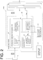
- FIG. 2 is a block diagram illustrating a schematic configuration of a first image display portion.
- a stereo image display device 1 has function of allowing an observer at a viewpoint VP to observe a stereo image based on a binocular parallax.
- the stereo image display device 1 includes a first image display portion 3, a second image display portion 5, and a semi-transparent mirror 7.
- the first image display portion 3 is provided in a substantially horizontal position with an image screen facing downwardly.
- the second image display portion 5 is provided in a standing position with an image screen extending in a vertical direction on a back side of the first image display portion 3 when observed from the viewpoint VP.
- a corner portion is formed at a position, where the first image display portion 3 and the second image display portion 5 are connected with each other.
- a depth direction in FIG. 1 corresponds to the longitudinal direction of the display portions.
- the semi-transparent mirror 5 has a back end attached to the corner portion, and is provided to extend toward the viewpoint VP with the other end thereof provided obliquely and downwardly.
- a right-eye image (first image) displayed on the first image display portion 3 is reflected by the semi-transparent mirror 7 toward the viewpoint VP.
- a left-eye image (second image) displayed on the second image display portion 5 transmits through the semi-transparent mirror 7 toward the viewpoint VP.
- the first image display portion 3 corresponds to "a first image display means” of the present invention
- the second image display portion 5 corresponds to "a second image display means” of the present invention.
- first image display portion 3 will be described in detail.
- the explanation will be made with an example of the first image display portion 3 because the first image display portion 3 and the second image display portion 5 are similar in terms of block diagrams except for parameters, which will be described later.
- the first image display portion 3 includes a video input portion 9, a first video output portion 11, a first luminance adjustment portion 13, a computation portion 15, a calibration coefficient storage portion 17, and a semi-transparent mirror correction coefficient storage portion 19.
- the video input portion 9 receives a video signal, which includes a right-eye image among stereo-vision images, from a host (such as a computer).
- the first video output portion 11 includes, for example, a liquid crystal display panel, and displays the right-eye image based on the video signal.
- the first luminance adjustment portion 13 includes, for example, a backlight, and adjusts a luminance of the first image output portion 11 based on a luminance input signal.
- the calibration coefficient storage portion 17 prestores a calibration coefficient, which is obtained through calibration.
- the calibration coefficient includes a chromaticity correction value and a gamma correction value, and will be described later as a chromaticity correction coefficient Cc.
- the process of the calibration may be executed during the production of the stereo image display device 1, or may be executed by a user of the device 1.
- the semi-transparent mirror correction coefficient storage portion 19 prestores a semi-transparent mirror luminance correction coefficient b and a semi-transparent mirror chromaticity correction coefficient C M , which will be described later.
- the semi-transparent mirror luminance correction coefficient b is a reflection-side value based on a reflectance ratio and a transmittance ratio of the semi-transparent mirror 7.
- the semi-transparent mirror chromaticity correction coefficient C M is a value based on a reflectance ratio of the semi-transparent mirror 7.
- the calibration coefficient storage portion 17 corresponds to "a calibration coefficient storage means" of the present invention
- the semi-transparent mirror correction coefficient storage portion 19 corresponds to "a semi-transparent mirror reflected luminance correction coefficient storage means", "a semi-transparent mirror luminance correction coefficient storage means”, and "a semi-transparent mirror reflected chromaticity correction coefficient storage means" of the present invention.
- the computation portion 15 includes a chromaticity correction computation unit 21 and a luminance correction computation unit 23.
- the chromaticity correction computation unit 21 corrects the video signal, which is received from the video input portion 9, based on the chromaticity correction coefficient Cc and based on the semi-transparent mirror chromaticity correction coefficient C M , and provides the corrected video signal to the first image output portion 11.
- the luminance correction computation unit 23 has a user setting storage portion 25 that stores a luminance set value, which is preset by the user (for example, observer) based on the user's preference.
- the luminance correction computation unit 23 corrects a luminance input signal L I based on the semi-transparent mirror luminance correction coefficient b, which is stored in the semi-transparent mirror correction coefficient storage portion 19, and provides the corrected signal, as a luminance input signal Lo, to the first luminance adjustment portion 13.
- the chromaticity correction computation unit 21 corresponds to "a chromaticity correcting means" of the present invention
- the luminance correction computation unit 23 corresponds to "a luminance correcting means” of the present invention
- the user setting storage portion 25 corresponds to "a user setting storage means” of the present invention.
- the second image display portion 5 has a configuration similar to the above first image display portion 5.
- the chromaticity correction coefficient Cc stored in the calibration coefficient storage portion 17 is collected during calibration of the second image display portion 5, and a luminance set value stored in the user setting storage portion 25 is set for the second image display portion 5.
- the semi-transparent mirror luminance correction coefficient b, which is stored in the semi-transparent mirror correction coefficient storage portion 19, and the semi-transparent mirror chromaticity correction coefficient C M are set for the second image display portion 5.
- the semi-transparent mirror luminance correction coefficient b is a transmittance side value based on the reflectance ratio and the transmittance ratio of the semi-transparent mirror 7
- the semi-transparent mirror chromaticity correction coefficient C M is a value based on the transmittance ratio of the semi-transparent mirror 7.
- the calibration coefficient storage portion 17 corresponds to "a calibration coefficient storage means" of the present invention
- the semi-transparent mirror correction coefficient storage portion 19 corresponds to "a semi-transparent mirror transmitted luminance correction coefficient storage means” and "a semi-transparent mirror transmitted chromaticity correction coefficient storage means" of the present invention.
- FIG. 3 is a chart illustrating a relation between a wavelength and tristimulus values and illustrating another relation between a wavelength and a reflectance ratio.
- the video signal (color related information) is inputted from the host through the video input portion 9, and the video signal is assumed to be an RGB value (RGB color system).
- RGB value RGB color system
- Tristimulus values which are invented three primary colors, match the photoreceptor sensitivity of the human eyes more than the RGB value, which represents three primary colors made based on the optical theory, does.
- the tristimulus values are used to calculate the correction coefficient.
- the tristimulus values are also referred to as an XYZ color system, and a stimulus value X is red (+ blue), a stimulus value Y is a luminance (+ green), and a stimulus value Z is blue.
- a reflectance ratio r( ⁇ ) of the semi-transparent mirror 7 for each wavelength is measured.
- the semi-transparent mirror 7 has an optical characteristic, in which a distribution of the reflectance ratio is different for different wavelength. This is also true for the transmittance ratio.
- the distribution of the reflectance ratio for different wavelength for each of the tristimulus values XYZ is considered based on the following equations (1) to (3).
- a range of the wavelength is set from 380 to 780 [nm] because it is only needed to consider the wavelength range that the human eyes are capable of sensing.
- the correction coefficient for the RGB value which serves as the video input signal, is calculated based on the reflectance ratio for each wavelength for the above tristimulus values.
- maximum values of the RGB value, which are outputted by the first image output portion 11, are defined as R Max , G Max , and B Max (for example, the maximum value is 255 for each color level of the RGB value), and the RGB value, which reaches the viewpoint VP through the semi-transparent mirror 7, is defined to include R' Max , G' Max , and B' Max .
- R' Max , G' Max , and B' Max are calculated by using the above equations (1) to (3) through the following equation (4).
- a matrix M is a conversion matrix for converting the RGB color space into the XYZ color space
- M -1 is a conversion matrix for converting the XYZ color space into the RGB color space.
- correction coefficients c r , c g , and c b in the RGB color space are computed by using the following equations (5) to (7).
- the term MIN indicates the function of extracting the minimum value among the values in the bracket.
- c r C MIN / R ′ Max
- c g C MIN / G ′ Max
- c b C MIN / B ′ Max
- Each of the above equations (5) to (7) means that one color level of the RGB value is reduced accordingly as another color level is reduced due to the reflectance ratio. In other words, one color level, which has been reduced due to the reflection by a smaller amount, is further reduced according to another color level, which has been reduced more due to the reflection, in order to balance the color.
- the following semi-transparent mirror chromaticity correction coefficient C M which is computed by the following equation (8), is stored in the semi-transparent mirror correction coefficient storage portion 19 shown in FIG. 1 .
- C M c r 0 0 0 c g 0 0 0 c b
- the chromaticity correction computation unit 21 executes correction computation based on the following equation (9).
- R o G o B o C M C c R I G I B I
- R I , G I , and B I in equation (9) serve as the input video signal, which is inputted into the video input portion 9 of the first image display portion 3, and Ro, Go, and Bo serve as the RGB value, which is outputted to the first image display portion 3.
- a matrix Cc is the chromaticity correction coefficient, which is stored in the calibration coefficient storage portion 17.
- the semi-transparent mirror chromaticity correction coefficient C M which is calculated by the above equation (8), is a value for correcting the influence caused by the reflection by the semi-transparent mirror 7.
- the semi-transparent mirror luminance correction coefficient b for correcting luminance difference between a reflection side and a transmittance side is computed based on a reflectance ratio ry (and a transmittance ratio) of the stimulus value Y.
- the reflectance ratio r Y (and the transmittance ratio) of the stimulus value Y are obtained in consideration of the wavelength computed during the process of obtaining the semi-transparent mirror chromaticity correction coefficient C M of the reflection side and the transmittance side.
- the semi-transparent mirror luminance correction coefficients b REF , b TRAN for the reflection side and the transmittance side are defined by the following equations (10) and (11).
- the reflectance ratio ry for the reflection side is defined as r Y REF
- the transmittance ratio ry for the transmittance side is defined as r Y TRAN .
- b REF r Y MIN / r Y REF
- b TRAN r Y MIN / r Y TRAN
- r Y MIN MIN r Y REF r Y TRAN
- a signal, which has not been corrected is defined as a luminance input signal L I
- a corrected signal is defined as a luminance input signal Lo.
- L o bL I
- the semi-transparent mirror luminance correction coefficients b are used for reducing the luminance of one of the transmittance side and the reflection side according to the luminance of the other one, which has the luminance reduced due to the transmittance or the reflection.
- the reflectance ratio r Y REF for the reflection side corresponds to "luminance reflectance ratio”
- the transmittance ratio r Y TRAN for the transmittance side corresponds to "luminance transmittance ratio”.
- the semi-transparent mirror luminance correction coefficient b REF corresponds to "semi-transparent mirror luminance correction coefficient of the reflection side”
- the luminance correction coefficient b TRAN corresponds to "semi-transparent mirror luminance correction coefficient of the transmittance side”.
- the luminance correction computation unit 23 corrects the luminance input signal, which is inputted into the first luminance adjustment portion 13, based on the semi-transparent mirror luminance correction coefficient b, and the luminance correction computation unit 23 corrects the luminance input signal, which is inputted into the second luminance adjustment portion 13, based on the semi-transparent mirror luminance correction coefficient. Therefore, the image of the first image display portion 3, which is reflected by the semi-transparent mirror 7, and the image of the second image display portion 5, which is allowed to transmit through the semi-transparent mirror 7, are respectively corrected to cancel a luminance difference according to the optical characteristic of the semi-transparent mirror 7, and thereby it is possible to suppress the luminance difference of the stereo image. As a result, it is possible to suppress uncomfortable feeling of the stereo image caused by the semi-transparent mirror 7.
- the luminance input signal is adjusted based on the luminance set value of the user setting storage portion 25, it is possible to reflect the luminance of the user's preference on the luminance input signal, and thereby the user, including the observer, is comfortably capable of having the binocular vision.
- the balance of the RGB value, which has become unbalanced due to the reflection is corrected based on the semi-transparent mirror chromaticity correction coefficient C M
- the balance of the RGB value, which has become unbalanced due to the transmittance is corrected based on the semi-transparent mirror chromaticity correction coefficient C M .
- the chromaticity correction computation unit 21 corrects the video signal based on the calibration coefficient stored in the calibration coefficient storage portion 17. As a result, it is possible to effectively use the result of the calibration executed by the user, and thereby it is possible for the user, including the observer, to more comfortably have the binocular vision.
- FIG. 4 is referred to for explaining the present modification.
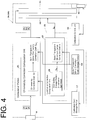
- FIG. 4 is a block diagram illustrating a first image display portion according to the modification.
- a first image display portion 3A internally includes a calibration sensor 31 inside a front bezel of the first image display portion 3.
- the calibration sensor 31 is controlled by a calibration control unit 33. For example, it is controlled such that the calibration sensor 31 is received within the front bezel in a normal state, and the calibration sensor 31 is advanced from the front bezel only during the execution of the calibration. In the advanced state, a photometric surface of the calibration sensor 31 is placed in tight contact with or is close to the screen of the first image output portion 11.
- a calibration coefficient, which is collected by the calibration sensor 31, is stored in the calibration coefficient storage portion 17. The above configuration is also provided to a second image display portion 5A.
- the user is capable of easily executing the calibration of the first image display portion 3A and the second image display portion 5A without the influence of ambient light.
- FIG. 5 is referred to for explaining the present modification.
- FIG. 5 is a side view illustrating a schematic configuration of a stereo image display device according to the second modification.
- the stereo image display device 1A includes a receiver 35, which is connected to the user setting storage portion 25 of the first image display portion 3, and includes a receiver 35, which is connected to the user setting storage portion 25 of the second image display portion 5.
- the receivers 35 are connected to a controller 37.
- the controller 37 has, for example, function of setting a parameter related to the stereo image display device 1A, and function of transmitting the set parameter.
- the controller 37 may be a personal computer connected to the stereo image display device 1A, or may be a switch, which is provided to the first image display portion 3 and the second image display portion 5 for adjusting the image quality.
- Each receiver 35 receives a luminance set value transmitted from the controller 37.
- the luminance set value received by each receiver 35 is written to the user setting storage portion 25, which is connected to the respective receiver 35.
- the luminance set value, which is transmitted from the controller 37 is a desired luminance value, which is set by the user. In other words, the same luminance set value is written to both of the user setting storage portions 25.
- Each receiver 35 and the controller 37 in the above description correspond to "a common value setting means" of the present invention.
- the user-preferred luminance value which is determined through the controller 37, is set in the first image display portion 3 and in the second image display portion 5.
- the luminance set values of the first image display portion 3 and the second image display portion 5 are set equivalent to each other.
- the luminance balance of the images displayed on both image display portions 3, 5 is maintained.
- FIG. 6 is referred to for explaining the present modification.
- FIG. 6 is a side view illustrating a schematic configuration of stereo image display device according to the third modification.
- the same luminance set value is set in parallel to the first image display portion 3 and the second image display portion 5.
- a stereo image display device 1B according to the third modification is different from the second modification in a configuration, where the luminance set value is written in series.
- the second image display portion 5 has a receiver 35 and a communication portion 38.
- the first image display device 3 has a communication portion 39.
- the receiver 35 receives a luminance set value, which is sent from the controller 37, and which is set to a desired value by the user.
- the receiver 35 writes the received luminance set value in the user setting storage portion 25 of the second image display portion 5.
- the communication portion 38 sends the updated luminance set value to the communication portion 39 of the first image display portion 3.
- the communication portion 39 writes the received luminance set value in the user setting storage portion 25.
- the receiver 35, the controller 37, and the communication portions 38, 39 in the above configuration correspond to "a synchronous setting means" of the present invention.
- the controller 37 changes the set luminance value of the second image display portion 5 based on the luminance value, which is wanted by the user, the set luminance value of the first image display portion 3 is synchronously changed to the same value.
- the other one of the luminance values is also set to the same value.
- the luminance balance of the images displayed on both image display portions 3, 5 is maintained.
- the first image display portion 3 is provided with the communication portion 39
- the second image display portion 5 is provided with the communication portion 38.
- the luminance set value of the user setting storage portion 25 of the second image display portion 5 is changed, the same luminance set value is written in the user setting storage portion 25 of the first image display portion 3.
- the set luminance value received by the receiver 35 may be written in the user setting storage portion 25 of the first image display portion 3, and then the same set luminance value may be written in the user setting storage portion 25 of the second image display portion 5 through the communication portion 39 and the communication portion 38.
- FIG. 7 is referred to for explaining the present modification.
- FIG. 7 is a block diagram illustrating a first image display portion according to the fourth modification.
- the first image display portion 3 has a chromaticity correction computation unit 21A.
- the second image display portion 5 similarly has a color correction computation unit 21A.
- the chromaticity correction computation unit 21A has a user color setting storage portion 41.
- the user color setting storage portion 41 stores a user color correction coefficient, which is set by the user.
- the user color correction coefficient corresponds to, for example, a gain adjustment or a contrast setting.
- the color correction computation unit 21A executes correction computation based on the following equation (14), which replaces the equation (9), where the user color correction coefficient is denoted by a numeral Cu.
- R o G o B o C M C U C c R I G I B I
- the above user color setting storage portion 41 corresponds to "a user setting color correction coefficient storage means" of the present invention.
- the first image display portion 3 and the second image display portion 5 have the same values when the user color correction coefficient stored in the user color setting storage portion 41 is changed by the user. Due to the above, even when the above correction related to the semi-transparent mirror 7 is executed, the chromaticity balance of the images displayed on both image display portions 3, 5 is maintained.
- FIG. 8 is referred to for explaining the present modification.
- FIG. 8 is a block diagram illustrating a first image display portion and a setting unit according to the fifth modification.
- a stereo image display device 1C has a display device main body 51 and a setting unit 53.
- the display device main body 51 has a first image display device 3 and a second image display device 5.
- the calibration coefficient storage portion 17 and the semi-transparent mirror correction coefficient storage portion 19 are not provided to the display device main body 51, but are provided to the setting unit 53, which is separate from the display device main body 51.
- the setting unit 53 has a correction coefficient computation unit 55.
- the correction coefficient computation unit 55 obtains a mirror calibration chromaticity correction coefficient (C M •C C ) based on the chromaticity correction coefficient Cc, which is prestored in the calibration coefficient storage portion 17, and based on the semi-transparent mirror chromaticity correction coefficient C M , which is prestored in the semi-transparent mirror correction coefficient storage portion 19.
- the obtained mirror calibration chromaticity correction coefficient (C M •C C ) is set in the chromaticity correction computation unit 21.
- the semi-transparent mirror luminance correction coefficient b which is stored in the semi-transparent mirror correction coefficient storage portion 19, is set in the luminance correction computation unit 23.
- the correction coefficient computation unit 55 corresponds to "a computation means" of the present invention
- the mirror calibration chromaticity correction coefficient (C M •C C ) corresponds to "mirror calibration correction coefficient” of the present invention.
- FIG. 9 is referred to for explaining the present modification.
- FIG. 9 is a longitudinal sectional view illustrating a preferable configuration of the semi-transparent mirror.
- the above semi-transparent mirror 7 is preferable to have a configuration of a semi-transparent mirror 7A in the following manner.
- an angle defined between the first image display portion 3 and the second image display portion 5, which constitute a stereo image display device 1D is designed to be about 110 degrees, greater than 90 degrees.
- the configuration except the semi-transparent mirror 7A is generally similar to the above embodiment.
- the first image display portion 3 and the second image display portion 5 are respectively provided with linearly polarizing plates 63 on their front surfaces, and that the linearly polarizing plates 63 have the same polarizing characteristic.
- each linearly polarizing plate 63 has a polarizing direction that extends in a vertical direction.
- the semi-transparent mirror 7A has a half-wave plate 65, a linearly polarizing plate 67, and a semi-transparent mirror portion 69, which are stacked upon one another in the order from the side of the semi-transparent mirror 7A, on which light from the second image display portion 5 is incident.
- Adherence for the parts may preferably employ an optical adhesive that has a refractive index similar to that of the material of the semi-transparent mirror portion 69.
- the semi-transparent mirror portion 69 has a transparent layer 71 and a semi-transparent mirror layer 73 as shown in an enlarged partial view in FIG. 9 .
- the transparent layer 71 is made of a material (such as glass or synthetic resin), which is optically transparent.
- the semi-transparent mirror layer 73 is adhered to the transparent layer 71 through a method such as evaporation.
- the half-wave plate 65 corresponds to "polarization rotating layer” of the present invention
- the linearly polarizing plate 67 corresponds to "linearly polarizing layer” of the present invention.
- the half-wave plate 65 has function of rotating a polarizing direction of linearly polarized light.
- the polarizing direction of light which is emitted from the second image display portion 5, and which is polarized in the vertical direction, is rotated by 90 degrees, to be polarized in a horizontal direction.
- the linearly polarizing plate 67 has function of suppressing dispersion of the wavelength of light, which may be caused by the birefringence by using the half-wave plate 65.
- the transmittance of the light from the second image display portion 5 through the semi-transparent mirror 7A is capable of suppressing a rainbow pattern, which may be caused by birefringence, and the change of the display color.
- the numeral 75 indicates eyeglasses with polarizing plates for the observer.
- the eyeglasses 75 with polarizing plates has a right-eye linearly polarizing plate 77R and a left-eye linearly polarizing plate 77L.
- the right-eye linearly polarizing plate 77R is polarized in a vertical direction
- the left-eye linearly polarizing plate 77L is polarized in a horizontal direction.
- the observer is capable of solely observing the left-eye image (polarized in the horizontal direction) of the second image display portion 5, which transmits through the semi-transparent mirror 7A, with the left eye.
- the observer is capable of observing the stereo image.
- the images displayed on the first image display portion 3 and the second image display portion 5 are made to have different polarizing directions from each other. As a result, it is not needed to differentiate the linearly polarizing plates 63, which are provided to the first image display portion 3 and the second image display portion 5. Therefore, the first image display portion 3 and the second image display portion 5 are configured to have the linearly polarizing plates 63 having the same structure. As a result, it is possible to reduce the manufacturing cost of the stereo image display device 1D.
- the present invention is not limited to the above embodiments, and may be modified in the following manner.
- the present invention is suitable to a stereo image display device that makes a stereo image recognizable.
Landscapes
- Physics & Mathematics (AREA)
- Engineering & Computer Science (AREA)
- General Physics & Mathematics (AREA)
- Multimedia (AREA)
- Optics & Photonics (AREA)
- Signal Processing (AREA)
- Computer Hardware Design (AREA)
- Theoretical Computer Science (AREA)
- Testing, Inspecting, Measuring Of Stereoscopic Televisions And Televisions (AREA)
- Stereoscopic And Panoramic Photography (AREA)
- Liquid Crystal Display Device Control (AREA)
- Control Of Indicators Other Than Cathode Ray Tubes (AREA)
- Controls And Circuits For Display Device (AREA)
Description
- The present invention relates to a stereo image display device that is capable of making a stereo image recognized based on a right-eye image and a left-eye image, and specially relates to a technique that enables binocular vision through a semi-transparent mirror.
- Conventionally, a device of the above type may be a stereo image display device, which includes, for example, a first display portion configured to display a first image serving as a left-eye image, a second display portion configured to display a second image serving as a right-eye image, a semi-transparent mirror provided at a corner portion formed between the first display portion and the second display portion, a chromaticity adjusting portion configured to adjust a chromaticity of the first display portion and the second display portion, and a luminance adjusting portion configured to adjust a luminance of the first display portion and the second display portion (for example, see Patent Document 1). The above stereo image display device suppresses the variation of chromaticity and luminance of both of the display portions through the chromaticity adjusting portion and the luminance adjusting portion.
- In the above conventional device, although nothing is described about the calibration, an optical sensor is used for the calibration in general. Although different from the above stereo image device, the followings are examples, in which the optical sensor is used for a display device capable of displaying a two dimensional image.
- There is a first image display device that includes a calibration optical sensor provided separate from the image display device, and the optical sensor is brought into a tight contact with a liquid crystal display panel to execute the calibration (for example, see Patent Document 2). The device is capable of accurately executing the calibration without the influence of disturbance, such as ambient light.
- Also, there is a second image display device, in which a calibration optical sensor is provided to a bezel part of the liquid crystal display panel (for example, see Patent Document 3). The above device is configured such that, the optical sensor is received within the bezel part when the liquid crystal display panel is caused to display the image, and also that the optical sensor is advanced toward the liquid crystal display panel only when the calibration is executed. As a result, when the image is displayed, the optical sensor will not hinder the display, In addition to it, when the calibration is executed, the optical sensor is advanced so that the calibration is quickly executed. Also, the device is capable of accurately executing the calibration without the influence of disturbance, such as ambient light.
- In order to execute the calibration for the above conventional stereo image display device, for example, it is assumed that a calibration optical sensor is provided at a viewpoint located between the semi-transparent mirror of the stereo image display device and the observer. It is also assumed that, for example, the calibration optical sensor described in the
above Patent Document 2 is provided to each of the display portions. - Patent Document 1:
JP-A-2004-241962 FIG. 1 ,FIG. 2 ) - Patent Document 2:
JP3751621 FIG. 1 ) - Patent Document 3:
JP-A-2007-193355 FIG. 1 ) - A further conventional stereo image display device is disclosed in
US 2004/223223379 A1 - However, in the case of the conventional examples having the above configuration, the following problems exist.
- In the conventional former device, the display portion is separate from the optical sensor, and thereby the device is suffered from the adverse influence of the disturbance, such as the ambient light. As a result, the calibration needs to be executed in a dark room. Thereby, it is inconvenient for the user to execute the calibration, and also the optical sensor needs to be highly sensitive because the distance between the display portion and the optical sensor is long. Therefore, the former device is not practical.
- In case of the stereo image display device, the conventional latter device has a practical configuration. However, even when the calibration is executed with the calibration coefficients obtained at each of the first display portion and the second display portion, the chromaticity and luminance between the left-eye image and the right-eye image at the viewpoint become unbalanced due to a reflection characteristic and a transmittance characteristic of the semi-transparent mirror. As a result, even the latter device may cause uncomfortable feeling of the stereo image disadvantageously. Specially, since human eyes are sensitive more to the luminance than the chromaticity, it is important to balance the luminance of the right-eye image and the left-eye image in order to achieve natural binocular vision.
- The present invention is made in view of the above situation, and therefore it is an objective of the present invention to provide a stereo image display device that is capable of suppressing uncomfortable feeling of a stereo image, which is caused by a semi-transparent mirror, in consideration of a characteristic of the semi-transparent mirror, and that is capable of providing improved flexibility for calibration environment.
- The present invention provides an image stereo display device according to
claim 1. - [Operation/Effect] According to the invention of
claim 1, the image displayed on the first video output portion provided to the first image display means is emitted by the luminance adjusted by the first luminance adjustment portion, and is reflected by the semi-transparent mirror to the observer. Also, the image displayed on the second video output portion provided to the second image display means is emitted by the luminance adjusted by the second luminance adjustment portion, and is allowed to transmit through the semi-transparent mirror toward the observer. In the above state, even when the first luminance adjustment portion and the second luminance adjustment portion have the same luminance, eyes of the observer may have uncomfortable feeling of the binocular vision because the luminance difference may be caused by the reflection characteristic and the transmittance characteristic of the semi-transparent mirror. Thus, the luminance correcting means adjusts to cancel a luminance difference of the image of the first image display means reflected by the semi-transparent mirror and the image of the second image display means that is allowed to transmit through the semi-transparent mirror based on the semi-transparent mirror luminance correction coefficient stored in the semi-transparent mirror luminance correction coefficient storage means. As a result, the image of the first image display means reflected by the semi-transparent mirror and the image of the second image display means that is allowed to transmit through the semi-transparent mirror are corrected such that the luminance difference is cancelled according to the optical characteristic of the semi-transparent mirror, and thereby it is possible to suppress the luminance difference of the stereo image. As a result, it is possible to suppress the uncomfortable feeling of the stereo image caused by the semi-transparent mirror. - Also, during the calibration, since it is not needed to consider the characteristic of the semi-transparent mirror, it is possible to separately execute the calibration of each of the first image display means and the second image display means. As a result, it is possible to execute the calibration in a state, where the calibration optical sensor and the like is brought into a tight contact with or is close to the first image display means and the second image display means, and thereby it is possible to improve the flexibility of the calibration environment.
- The semi-transparent mirror luminance correction coefficients stored in the semi-transparent mirror luminance correction coefficient storage means are obtained based on the reflectance ratio and the transmittance ratio of the semi-transparent mirror, which are measured in advance. Also, the semi-transparent mirror luminance correction coefficient is used for calculating a state, where light from the first luminance adjustment portion is reflected by the semi-transparent mirror and where light from the second luminance adjustment portion is allowed to transmit through the semi-transparent mirror, and then the coefficient is used for reducing one luminance according to the other luminance that is to become smaller.
- According to the stereo image display device of the present invention, the luminance correcting means corrects the luminance input signal, which is inputted into the first luminance adjustment portion, based on the semi-transparent mirror luminance correction coefficient stored in the semi-transparent mirror reflected luminance correction coefficient storage means, and the luminance correcting means corrects the luminance input signal, which is inputted into the second luminance adjustment portion, based on the semi-transparent mirror luminance correction coefficient stored in the semi-transparent mirror transmitted luminance correction coefficient storage means. As a result, it is possible to correct the image of the first image display means reflected by the semi-transparent mirror and the image of the second image display means that is allowed to transmit through the semi-transparent mirror in order to cancel the luminance difference according to the optical characteristic of the semi-transparent mirror, and thereby it is possible to suppress the luminance difference of the stereo image. As a result, it is possible to suppress the uncomfortable feeling of the stereo image caused by the semi-transparent mirror.
- Also, during the calibration, since it is not required to consider the characteristic of the semi-transparent mirror, it is possible to separately execute the calibration of each of the first image display means and the second image display means. As a result, it is possible to execute the calibration in a state, where the calibration optical sensor and the like is brought into a tight contact with or is close to the first image display means and the second image display means, and thereby it is possible to improve the flexibility of the calibration environment.
-
- [
FIG. 1] FIG. 1 is a side view illustrating a schematic configuration of a stereo image display device according to an embodiment. - [
FIG. 2] FIG. 2 is a block diagram illustrating a schematic configuration of a first image display portion. - [
FIG. 3] FIG. 3 is a chart indicating a relation between a wavelength and a tristimulus values and indicating another relation between the wavelength and a reflectance ratio. - [
FIG. 4] FIG. 4 is a block diagram illustrating a first image display portion according to the first modification. - [
FIG. 5] FIG. 5 is a side view illustrating a schematic configuration of a stereo image display device according to the second modification. - [
FIG. 6] FIG. 6 is a side view illustrating a schematic configuration of a stereo image display device according to the third modification. - [
FIG. 7] FIG. 7 is a block diagram illustrating a first image display portion according to the fourth modification. - [
FIG. 8] FIG. 8 is a block diagram illustrating a first image display portion and a setting unit according to the fifth modification. - [
FIG. 9] FIG. 9 is a longitudinal sectional view illustrating a preferable configuration of a semi-transparent mirror. -
- 1, 1A to 1D ...
- stereo image display device
- VP ...
- viewpoint
- 3 ...
- first image display portion
- 5 ...
- second image display portion
- 7, 7A ...
- semi-transparent mirror
- 9 ...
- video input portion
- 11 ...
- first image output portion, second image output portion
- 13 ...
- first luminance adjustment portion, second luminance adjustment portion
- 15 ...
- computation portion
- 17 ...
- calibration coefficient storage portion
- 19 ...
- semi-transparent mirror correction coefficient storage portion
- 21 ...
- chromaticity correction computation unit
- 23 ...
- luminance correction computation unit
- Cc ...
- chromaticity correction coefficient
- CM ...
- semi-transparent mirror chromaticity correction coefficient
- 25 ...
- user setting storage portion
- LI ...
- luminance input signal
- b ...
- semi-transparent mirror luminance correction coefficient
- Lo ...
- corrected luminance input signal
- 31 ...
- calibration sensor
- 33 ...
- calibration control unit
- 51 ...
- display device main body
- 53 ...
- setting unit
- 55 ...
- correction coefficient computation unit
- One embodiment of the present invention will be described below with reference to accompanying drawings.
FIG. 1 is a side view illustrating a schematic configuration of a stereo image display device according to the embodiment, andFIG. 2 is a block diagram illustrating a schematic configuration of a first image display portion. - A stereo
image display device 1 according to the present embodiment has function of allowing an observer at a viewpoint VP to observe a stereo image based on a binocular parallax. - The stereo
image display device 1 includes a firstimage display portion 3, a secondimage display portion 5, and asemi-transparent mirror 7. In the embodiment, the firstimage display portion 3 is provided in a substantially horizontal position with an image screen facing downwardly. The secondimage display portion 5 is provided in a standing position with an image screen extending in a vertical direction on a back side of the firstimage display portion 3 when observed from the viewpoint VP. A corner portion is formed at a position, where the firstimage display portion 3 and the secondimage display portion 5 are connected with each other. For example, if the firstimage display portion 3 and the secondimage display portion 5 have horizontally oriented screens, a depth direction inFIG. 1 corresponds to the longitudinal direction of the display portions. Thesemi-transparent mirror 5 has a back end attached to the corner portion, and is provided to extend toward the viewpoint VP with the other end thereof provided obliquely and downwardly. - Due to the above configuration, for example, a right-eye image (first image) displayed on the first
image display portion 3 is reflected by thesemi-transparent mirror 7 toward the viewpoint VP. In contrast, a left-eye image (second image) displayed on the secondimage display portion 5 transmits through thesemi-transparent mirror 7 toward the viewpoint VP. - The first
image display portion 3 corresponds to "a first image display means" of the present invention, and the secondimage display portion 5 corresponds to "a second image display means" of the present invention. - Next, the first
image display portion 3 will be described in detail. The explanation will be made with an example of the firstimage display portion 3 because the firstimage display portion 3 and the secondimage display portion 5 are similar in terms of block diagrams except for parameters, which will be described later. - The first
image display portion 3 includes a video input portion 9, a firstvideo output portion 11, a firstluminance adjustment portion 13, acomputation portion 15, a calibrationcoefficient storage portion 17, and a semi-transparent mirror correctioncoefficient storage portion 19. The video input portion 9 receives a video signal, which includes a right-eye image among stereo-vision images, from a host (such as a computer). The firstvideo output portion 11 includes, for example, a liquid crystal display panel, and displays the right-eye image based on the video signal. The firstluminance adjustment portion 13 includes, for example, a backlight, and adjusts a luminance of the firstimage output portion 11 based on a luminance input signal. The calibrationcoefficient storage portion 17 prestores a calibration coefficient, which is obtained through calibration. The calibration coefficient includes a chromaticity correction value and a gamma correction value, and will be described later as a chromaticity correction coefficient Cc. The process of the calibration may be executed during the production of the stereoimage display device 1, or may be executed by a user of thedevice 1. Also, the semi-transparent mirror correctioncoefficient storage portion 19 prestores a semi-transparent mirror luminance correction coefficient b and a semi-transparent mirror chromaticity correction coefficient CM, which will be described later. The semi-transparent mirror luminance correction coefficient b is a reflection-side value based on a reflectance ratio and a transmittance ratio of thesemi-transparent mirror 7. The semi-transparent mirror chromaticity correction coefficient CM is a value based on a reflectance ratio of thesemi-transparent mirror 7. - In the above configuration of the first
image display portion 3, the calibrationcoefficient storage portion 17 corresponds to "a calibration coefficient storage means" of the present invention, and the semi-transparent mirror correctioncoefficient storage portion 19 corresponds to "a semi-transparent mirror reflected luminance correction coefficient storage means", "a semi-transparent mirror luminance correction coefficient storage means", and "a semi-transparent mirror reflected chromaticity correction coefficient storage means" of the present invention. - The
computation portion 15 includes a chromaticitycorrection computation unit 21 and a luminancecorrection computation unit 23. The chromaticitycorrection computation unit 21 corrects the video signal, which is received from the video input portion 9, based on the chromaticity correction coefficient Cc and based on the semi-transparent mirror chromaticity correction coefficient CM, and provides the corrected video signal to the firstimage output portion 11. The luminancecorrection computation unit 23 has a usersetting storage portion 25 that stores a luminance set value, which is preset by the user (for example, observer) based on the user's preference. The luminancecorrection computation unit 23 corrects a luminance input signal LI based on the semi-transparent mirror luminance correction coefficient b, which is stored in the semi-transparent mirror correctioncoefficient storage portion 19, and provides the corrected signal, as a luminance input signal Lo, to the firstluminance adjustment portion 13. - The chromaticity
correction computation unit 21 corresponds to "a chromaticity correcting means" of the present invention, and the luminancecorrection computation unit 23 corresponds to "a luminance correcting means" of the present invention. Also, the user settingstorage portion 25 corresponds to "a user setting storage means" of the present invention. - The second
image display portion 5 has a configuration similar to the above firstimage display portion 5. However, the chromaticity correction coefficient Cc stored in the calibrationcoefficient storage portion 17 is collected during calibration of the secondimage display portion 5, and a luminance set value stored in the user settingstorage portion 25 is set for the secondimage display portion 5. Also, the semi-transparent mirror luminance correction coefficient b, which is stored in the semi-transparent mirror correctioncoefficient storage portion 19, and the semi-transparent mirror chromaticity correction coefficient CM are set for the secondimage display portion 5. In other words, the semi-transparent mirror luminance correction coefficient b is a transmittance side value based on the reflectance ratio and the transmittance ratio of thesemi-transparent mirror 7, and the semi-transparent mirror chromaticity correction coefficient CM is a value based on the transmittance ratio of thesemi-transparent mirror 7. - In the configuration of the second
image display portion 5, the calibrationcoefficient storage portion 17 corresponds to "a calibration coefficient storage means" of the present invention, and the semi-transparent mirror correctioncoefficient storage portion 19 corresponds to "a semi-transparent mirror transmitted luminance correction coefficient storage means" and "a semi-transparent mirror transmitted chromaticity correction coefficient storage means" of the present invention. - Next, a method of calculating the semi-transparent mirror chromaticity correction coefficient CM and the semi-transparent mirror luminance correction coefficient b will be described with reference to
FIG. 3. FIG. 3 is a chart illustrating a relation between a wavelength and tristimulus values and illustrating another relation between a wavelength and a reflectance ratio. - Firstly, the method of calculating the semi-transparent mirror chromaticity correction coefficient CM will be described.
- The video signal (color related information) is inputted from the host through the video input portion 9, and the video signal is assumed to be an RGB value (RGB color system). Tristimulus values, which are invented three primary colors, match the photoreceptor sensitivity of the human eyes more than the RGB value, which represents three primary colors made based on the optical theory, does. Thus, in the present embodiment, the tristimulus values are used to calculate the correction coefficient. The tristimulus values are also referred to as an XYZ color system, and a stimulus value X is red (+ blue), a stimulus value Y is a luminance (+ green), and a stimulus value Z is blue.
- As shown in
FIG. 3 , firstly, a reflectance ratio r(λ) of thesemi-transparent mirror 7 for each wavelength is measured. Thesemi-transparent mirror 7 has an optical characteristic, in which a distribution of the reflectance ratio is different for different wavelength. This is also true for the transmittance ratio. Thus, firstly, the distribution of the reflectance ratio for different wavelength for each of the tristimulus values XYZ is considered based on the following equations (1) to (3). A range of the wavelength is set from 380 to 780 [nm] because it is only needed to consider the wavelength range that the human eyes are capable of sensing.


- Next, the correction coefficient for the RGB value, which serves as the video input signal, is calculated based on the reflectance ratio for each wavelength for the above tristimulus values. Firstly, maximum values of the RGB value, which are outputted by the first
image output portion 11, are defined as RMax, GMax, and BMax (for example, the maximum value is 255 for each color level of the RGB value), and the RGB value, which reaches the viewpoint VP through thesemi-transparent mirror 7, is defined to include R'Max, G'Max, and B'Max. R'Max, G'Max, and B'Max are calculated by using the above equations (1) to (3) through the following equation (4). Note that a matrix M is a conversion matrix for converting the RGB color space into the XYZ color space, and M-1 is a conversion matrix for converting the XYZ color space into the RGB color space.
- By using the above R'Max, G'Max, and B'Max, correction coefficients cr, cg, and cb in the RGB color space are computed by using the following equations (5) to (7). In the equations, CMIN indicates that CMIN = MIN(R'Max, G'Max, B'Max). The term MIN indicates the function of extracting the minimum value among the values in the bracket.


- Each of the above equations (5) to (7) means that one color level of the RGB value is reduced accordingly as another color level is reduced due to the reflectance ratio. In other words, one color level, which has been reduced due to the reflection by a smaller amount, is further reduced according to another color level, which has been reduced more due to the reflection, in order to balance the color.
- The following semi-transparent mirror chromaticity correction coefficient CM, which is computed by the following equation (8), is stored in the semi-transparent mirror correction
coefficient storage portion 19 shown inFIG. 1 .
- The chromaticity
correction computation unit 21 executes correction computation based on the following equation (9).
- RI, GI, and BI in equation (9) serve as the input video signal, which is inputted into the video input portion 9 of the first
image display portion 3, and Ro, Go, and Bo serve as the RGB value, which is outputted to the firstimage display portion 3. Also, a matrix Cc is the chromaticity correction coefficient, which is stored in the calibrationcoefficient storage portion 17. - The semi-transparent mirror chromaticity correction coefficient CM, which is calculated by the above equation (8), is a value for correcting the influence caused by the reflection by the
semi-transparent mirror 7. The value, which is calculated through the above equation (8) by replacing the reflectance ratio with the transmittance ratio during the above calculating process, is a value for correcting the influence caused by the transmittance through thesemi-transparent mirror 7. - Next, a method of calculating the semi-transparent mirror luminance correction coefficient b will be described.
- The semi-transparent mirror luminance correction coefficient b for correcting luminance difference between a reflection side and a transmittance side is computed based on a reflectance ratio ry (and a transmittance ratio) of the stimulus value Y. The reflectance ratio rY (and the transmittance ratio) of the stimulus value Y are obtained in consideration of the wavelength computed during the process of obtaining the semi-transparent mirror chromaticity correction coefficient CM of the reflection side and the transmittance side. The semi-transparent mirror luminance correction coefficients bREF, bTRAN for the reflection side and the transmittance side are defined by the following equations (10) and (11). The reflectance ratio ry for the reflection side is defined as rY REF, and the transmittance ratio ry for the transmittance side is defined as rY TRAN.


- In the above, rY MIN is defined by the following equation (12).

- In the luminance
correction computation unit 23 shown inFIG. 1 , the computation shown in the following equation (13) is executed. Here, a signal, which has not been corrected, is defined as a luminance input signal LI, and a corrected signal is defined as a luminance input signal Lo.
- In the above, the semi-transparent mirror luminance correction coefficient b satisfies b=bREF in case of the reflection side, and is stored in the semi-transparent mirror correction
coefficient storage portion 19 of the firstimage display portion 3. Also, b=bTRAN is satisfied in case of the transmittance side, and is stored in the semi-transparent mirror correctioncoefficient storage portion 19 of the secondimage display portion 5. Thus, it is meant that the semi-transparent mirror luminance correction coefficients b are used for reducing the luminance of one of the transmittance side and the reflection side according to the luminance of the other one, which has the luminance reduced due to the transmittance or the reflection. - The reflectance ratio rY REF for the reflection side corresponds to "luminance reflectance ratio", and the transmittance ratio rY TRAN for the transmittance side corresponds to "luminance transmittance ratio". Also, the semi-transparent mirror luminance correction coefficient bREF corresponds to "semi-transparent mirror luminance correction coefficient of the reflection side", and the luminance correction coefficient bTRAN corresponds to "semi-transparent mirror luminance correction coefficient of the transmittance side".
- According to the present embodiment device, the luminance
correction computation unit 23 corrects the luminance input signal, which is inputted into the firstluminance adjustment portion 13, based on the semi-transparent mirror luminance correction coefficient b, and the luminancecorrection computation unit 23 corrects the luminance input signal, which is inputted into the secondluminance adjustment portion 13, based on the semi-transparent mirror luminance correction coefficient. Therefore, the image of the firstimage display portion 3, which is reflected by thesemi-transparent mirror 7, and the image of the secondimage display portion 5, which is allowed to transmit through thesemi-transparent mirror 7, are respectively corrected to cancel a luminance difference according to the optical characteristic of thesemi-transparent mirror 7, and thereby it is possible to suppress the luminance difference of the stereo image. As a result, it is possible to suppress uncomfortable feeling of the stereo image caused by thesemi-transparent mirror 7. - Also, since the luminance input signal is adjusted based on the luminance set value of the user setting
storage portion 25, it is possible to reflect the luminance of the user's preference on the luminance input signal, and thereby the user, including the observer, is comfortably capable of having the binocular vision. - Furthermore, in the first
image display portion 3, the balance of the RGB value, which has become unbalanced due to the reflection, is corrected based on the semi-transparent mirror chromaticity correction coefficient CM, and in the secondimage display portion 5, the balance of the RGB value, which has become unbalanced due to the transmittance, is corrected based on the semi-transparent mirror chromaticity correction coefficient CM. As a result, it is possible to suppress the difference of the chromaticity between the reflected image and the transmitted image. As a result, the observer is capable of observing the stereo image in a state, where the chromaticity difference of the stereo image caused by thesemi-transparent mirror 7 is suppressed. Thereby, it is possible to further suppress the uncomfortable feeling of the stereo image related to the chromaticity. - Also, the chromaticity
correction computation unit 21 corrects the video signal based on the calibration coefficient stored in the calibrationcoefficient storage portion 17. As a result, it is possible to effectively use the result of the calibration executed by the user, and thereby it is possible for the user, including the observer, to more comfortably have the binocular vision. - Also, since it is not needed to consider the characteristic of the
semi-transparent mirror 7 during the calibration, it is possible to individually execute the calibration for each of the firstimage display portion 3 and the secondimage display portion 5. As a result, since it is possible to execute the calibration in a state, where a calibration optical sensor and the like is brought into tight contact with or is placed close to the firstimage display portion 3 and the secondimage display portion 5, it is possible to increase the flexibility of the calibration environment. - The above embodiment is not provided with a calibration sensor, and the calibration sensor is assumed to be a separate body. The present invention may employ an integral configuration, which is integral with the calibration sensor.
FIG. 4 is referred to for explaining the present modification.FIG. 4 is a block diagram illustrating a first image display portion according to the modification. - A first
image display portion 3A internally includes acalibration sensor 31 inside a front bezel of the firstimage display portion 3. Thecalibration sensor 31 is controlled by acalibration control unit 33. For example, it is controlled such that thecalibration sensor 31 is received within the front bezel in a normal state, and thecalibration sensor 31 is advanced from the front bezel only during the execution of the calibration. In the advanced state, a photometric surface of thecalibration sensor 31 is placed in tight contact with or is close to the screen of the firstimage output portion 11. A calibration coefficient, which is collected by thecalibration sensor 31, is stored in the calibrationcoefficient storage portion 17. The above configuration is also provided to a secondimage display portion 5A. - Due to the above configuration, the user is capable of easily executing the calibration of the first
image display portion 3A and the secondimage display portion 5A without the influence of ambient light. - In the above embodiment and the first modification, it is preferable to employ the following configuration.
FIG. 5 is referred to for explaining the present modification.FIG. 5 is a side view illustrating a schematic configuration of a stereo image display device according to the second modification. - The stereo
image display device 1A includes areceiver 35, which is connected to the user settingstorage portion 25 of the firstimage display portion 3, and includes areceiver 35, which is connected to the user settingstorage portion 25 of the secondimage display portion 5. Thereceivers 35 are connected to acontroller 37. Thecontroller 37 has, for example, function of setting a parameter related to the stereoimage display device 1A, and function of transmitting the set parameter. Specifically, for example, thecontroller 37 may be a personal computer connected to the stereoimage display device 1A, or may be a switch, which is provided to the firstimage display portion 3 and the secondimage display portion 5 for adjusting the image quality. - Each
receiver 35 receives a luminance set value transmitted from thecontroller 37. The luminance set value received by eachreceiver 35 is written to the user settingstorage portion 25, which is connected to therespective receiver 35. The luminance set value, which is transmitted from thecontroller 37, is a desired luminance value, which is set by the user. In other words, the same luminance set value is written to both of the user settingstorage portions 25. - Each
receiver 35 and thecontroller 37 in the above description correspond to "a common value setting means" of the present invention. - According to the configuration of the above stereo
image display device 1A, the user-preferred luminance value, which is determined through thecontroller 37, is set in the firstimage display portion 3 and in the secondimage display portion 5. As a result, even in a case, where the user adjusts the luminance to a desired degree, the luminance set values of the firstimage display portion 3 and the secondimage display portion 5 are set equivalent to each other. As a result, even when the correction related to the abovesemi-transparent mirror 7 is executed, the luminance balance of the images displayed on bothimage display portions - In the above embodiment and first modification, it is preferable to employ the following configuration.
FIG. 6 is referred to for explaining the present modification.FIG. 6 is a side view illustrating a schematic configuration of stereo image display device according to the third modification. - In the above second modification (the stereo
image display device 1A), the same luminance set value is set in parallel to the firstimage display portion 3 and the secondimage display portion 5. A stereoimage display device 1B according to the third modification is different from the second modification in a configuration, where the luminance set value is written in series. - Specifically, the second
image display portion 5 has areceiver 35 and acommunication portion 38. Also, the firstimage display device 3 has acommunication portion 39. Thereceiver 35 receives a luminance set value, which is sent from thecontroller 37, and which is set to a desired value by the user. Thereceiver 35 writes the received luminance set value in the user settingstorage portion 25 of the secondimage display portion 5. Also, when the luminance set value of the user settingstorage portion 25 of the secondimage display portion 5 is updated, thecommunication portion 38 sends the updated luminance set value to thecommunication portion 39 of the firstimage display portion 3. Thecommunication portion 39 writes the received luminance set value in the user settingstorage portion 25. - The
receiver 35, thecontroller 37, and thecommunication portions - According to the above stereo
image display device 1B, when thecontroller 37 changes the set luminance value of the secondimage display portion 5 based on the luminance value, which is wanted by the user, the set luminance value of the firstimage display portion 3 is synchronously changed to the same value. As a result, even when the user changes one of the luminance values, the other one of the luminance values is also set to the same value. As a result, even when the correction related to the abovesemi-transparent mirror 7 is executed, the luminance balance of the images displayed on bothimage display portions - In the above example, the first
image display portion 3 is provided with thecommunication portion 39, and the secondimage display portion 5 is provided with thecommunication portion 38. When the luminance set value of the user settingstorage portion 25 of the secondimage display portion 5 is changed, the same luminance set value is written in the user settingstorage portion 25 of the firstimage display portion 3. However, alternatively, the set luminance value received by thereceiver 35 may be written in the user settingstorage portion 25 of the firstimage display portion 3, and then the same set luminance value may be written in the user settingstorage portion 25 of the secondimage display portion 5 through thecommunication portion 39 and thecommunication portion 38. - In the above embodiment and first modification, it is preferable to employ the following configuration.
FIG. 7 is referred to for explaining the present modification.FIG. 7 is a block diagram illustrating a first image display portion according to the fourth modification. - The first
image display portion 3 has a chromaticitycorrection computation unit 21A. Although not shown, the secondimage display portion 5 similarly has a colorcorrection computation unit 21A. The chromaticitycorrection computation unit 21A has a user colorsetting storage portion 41. The user colorsetting storage portion 41 stores a user color correction coefficient, which is set by the user. The user color correction coefficient corresponds to, for example, a gain adjustment or a contrast setting. The colorcorrection computation unit 21A executes correction computation based on the following equation (14), which replaces the equation (9), where the user color correction coefficient is denoted by a numeral Cu.
- The above user color
setting storage portion 41 corresponds to "a user setting color correction coefficient storage means" of the present invention. - According to the above configuration, it is possible to affect the display color of image with the preference of the user.
- Similarly to the above second modification and third modification, it is preferable to be configured that the first
image display portion 3 and the secondimage display portion 5 have the same values when the user color correction coefficient stored in the user colorsetting storage portion 41 is changed by the user. Due to the above, even when the above correction related to thesemi-transparent mirror 7 is executed, the chromaticity balance of the images displayed on bothimage display portions - The above embodiment and fourth modification may be alternatively configured in the following manner.
FIG. 8 is referred to for explaining the present modification.FIG. 8 is a block diagram illustrating a first image display portion and a setting unit according to the fifth modification. - A stereo image display device 1C has a display device
main body 51 and asetting unit 53. The display devicemain body 51 has a firstimage display device 3 and a secondimage display device 5. - The calibration
coefficient storage portion 17 and the semi-transparent mirror correctioncoefficient storage portion 19 are not provided to the display devicemain body 51, but are provided to thesetting unit 53, which is separate from the display devicemain body 51. The settingunit 53 has a correctioncoefficient computation unit 55. The correctioncoefficient computation unit 55 obtains a mirror calibration chromaticity correction coefficient (CM•CC) based on the chromaticity correction coefficient Cc, which is prestored in the calibrationcoefficient storage portion 17, and based on the semi-transparent mirror chromaticity correction coefficient CM, which is prestored in the semi-transparent mirror correctioncoefficient storage portion 19. The obtained mirror calibration chromaticity correction coefficient (CM•CC) is set in the chromaticitycorrection computation unit 21. Also, the semi-transparent mirror luminance correction coefficient b, which is stored in the semi-transparent mirror correctioncoefficient storage portion 19, is set in the luminancecorrection computation unit 23. - The correction
coefficient computation unit 55 corresponds to "a computation means" of the present invention, the mirror calibration chromaticity correction coefficient (CM•CC) corresponds to "mirror calibration correction coefficient" of the present invention. - Due to the above configuration, effects similar to those of the above embodiment are achievable. Furthermore, since various coefficients are stored in the
setting unit 53, which is separate from the display devicemain body 51, it is possible to connect thecommon setting unit 53 with multiple stereo image display devices 1C, and thereby it is possible to set the same coefficient in each of the multiple display devicemain bodies 51. As a result, it is possible to easily unify the display states of the multiple stereo image display devices 1C. Also, since it is possible to employ thesingle setting unit 53 to the multiple display devicemain bodies 51, it is possible to suppress the cost of the display devicemain bodies 51. - In the fifth modification, the configurations of the first to fourth modifications may be combined.
- In the above embodiment and the first to fifth modifications, it is preferable to employ the following configuration.
FIG. 9 is referred to for explaining the present modification.FIG. 9 is a longitudinal sectional view illustrating a preferable configuration of the semi-transparent mirror. - The above
semi-transparent mirror 7 is preferable to have a configuration of asemi-transparent mirror 7A in the following manner. InFIG. 9 , under the consideration of the viewability by the observer, an angle defined between the firstimage display portion 3 and the secondimage display portion 5, which constitute a stereoimage display device 1D, is designed to be about 110 degrees, greater than 90 degrees. The configuration except thesemi-transparent mirror 7A is generally similar to the above embodiment. For the convenience of the explanation, it is assumed that the firstimage display portion 3 and the secondimage display portion 5 are respectively provided with linearlypolarizing plates 63 on their front surfaces, and that the linearlypolarizing plates 63 have the same polarizing characteristic. In the present example, each linearly polarizingplate 63 has a polarizing direction that extends in a vertical direction. - The details of the
semi-transparent mirror 7A will be described. - The
semi-transparent mirror 7A has a half-wave plate 65, a linearly polarizingplate 67, and asemi-transparent mirror portion 69, which are stacked upon one another in the order from the side of thesemi-transparent mirror 7A, on which light from the secondimage display portion 5 is incident. Adherence for the parts may preferably employ an optical adhesive that has a refractive index similar to that of the material of thesemi-transparent mirror portion 69. Thesemi-transparent mirror portion 69 has atransparent layer 71 and asemi-transparent mirror layer 73 as shown in an enlarged partial view inFIG. 9 . Thetransparent layer 71 is made of a material (such as glass or synthetic resin), which is optically transparent. Thesemi-transparent mirror layer 73 is adhered to thetransparent layer 71 through a method such as evaporation. - The half-
wave plate 65 corresponds to "polarization rotating layer" of the present invention, and the linearly polarizingplate 67 corresponds to "linearly polarizing layer" of the present invention. - The half-
wave plate 65 has function of rotating a polarizing direction of linearly polarized light. For example, the polarizing direction of light, which is emitted from the secondimage display portion 5, and which is polarized in the vertical direction, is rotated by 90 degrees, to be polarized in a horizontal direction. The linearlypolarizing plate 67 has function of suppressing dispersion of the wavelength of light, which may be caused by the birefringence by using the half-wave plate 65. As a result, the transmittance of the light from the secondimage display portion 5 through thesemi-transparent mirror 7A is capable of suppressing a rainbow pattern, which may be caused by birefringence, and the change of the display color. Also, even when light emitted from the firstimage display portion 3 transmits through thesemi-transparent mirror portion 69 without being reflected by thesemi-transparent mirror portion 69, it is possible to absorb such light by the linearly polarizingplate 67 that has a different polarizing characteristic. As a result, it is possible to suppress the adverse influence caused by the part of light from the firstimage display portion 3, which transmits through thesemi-transparent mirror portion 69. - The numeral 75 indicates eyeglasses with polarizing plates for the observer. The
eyeglasses 75 with polarizing plates has a right-eye linearly polarizingplate 77R and a left-eye linearly polarizingplate 77L. In the example, the right-eye linearly polarizingplate 77R is polarized in a vertical direction, and the left-eye linearly polarizingplate 77L is polarized in a horizontal direction. As a result, when the observer has theeyeglasses 75 with polarizing plates, the observer is capable of solely observing the right-eye image (polarized in the vertical direction) of the firstimage display portion 3, which is reflected by thesemi-transparent mirror 7A, with the right eye. Also, the observer is capable of solely observing the left-eye image (polarized in the horizontal direction) of the secondimage display portion 5, which transmits through thesemi-transparent mirror 7A, with the left eye. As a result, the observer is capable of observing the stereo image. - By employing the above
semi-transparent mirror 7A, the images displayed on the firstimage display portion 3 and the secondimage display portion 5 are made to have different polarizing directions from each other. As a result, it is not needed to differentiate the linearlypolarizing plates 63, which are provided to the firstimage display portion 3 and the secondimage display portion 5. Therefore, the firstimage display portion 3 and the secondimage display portion 5 are configured to have the linearlypolarizing plates 63 having the same structure. As a result, it is possible to reduce the manufacturing cost of the stereoimage display device 1D. - The present invention is not limited to the above embodiments, and may be modified in the following manner.
- (1) The stereo image display device may be classified into an eyeglasses type and a naked-eye type. However, regardless of the above types, the above embodiment and the first to fifth modifications may be applied to any device that has the first
image display portion image display portion semi-transparent mirror 7. - (2) In the above embodiment, the luminance correction and the chromaticity correction are executed. However, it may be configured to execute only the luminance correction by omitting the chromaticity correction because the human vision is more sensitive to the luminance than the color. Due to the above, it is possible to simplify the device, and thereby it is possible to reduce the device cost.
- (3) In the above embodiment, the luminance set value, which is set by the user, and which is stored in the user setting
storage portion 25, is considered. However, the luminance set value may be omitted alternatively. - (4) In the above embodiment, the calibration coefficient of the calibration
coefficient storage portion 17 is considered. However, it is not needed to consider the calibration coefficient when the color correction values or the gamma correction values are identical for the twodisplay portions - (5) In the above embodiment, the stereo
image display device 1 has an inversed L shape when observed in a side view as shown inFIG. 1 . However, the firstimage display portion 3 may be alternatively placed at a bottom portion to form an L shape. In the above case, since the corner portion is located at the lower position, thesemi-transparent mirror 7 is provided obliquely and upwardly toward the viewpoint VP. - (6) In the above embodiment, the first
image display portion 3 and the secondimage display portion 5 are respectively provided with the semi-transparent mirror correctioncoefficient storage portion 19 and the luminancecorrection computation unit 23. However, the semi-transparent mirror correctioncoefficient storage portion 19 and the luminancecorrection computation unit 23 may be located at different positions as long as they are provided to the stereoimage display device 1. - As above, the present invention is suitable to a stereo image display device that makes a stereo image recognizable.
Claims (1)
- A stereo image display device (1) capable of displaying a stereo image based on a binocular parallax comprising:a first image display means (3) having:a first video output portion (11) configured to display one of a right-eye image and a left-eye image based on a video signal; anda first luminance adjustment portion (13) configured to adjust a luminance of the first video output portion based on a luminance input signal;a second image display means (5) provided to form a corner portion together with the first image display means, the second image display means having:a second video output portion (11) configured to display the other one of the right-eye image and the left-eye image based on a video signal; anda second luminance adjustment portion (13) configured to adjust a luminance of the second video output portion based on a luminance input signal;a semi-transparent mirror (7) obliquely provided from the corner portion, the semi-transparent mirror (7) configured to reflect the image, which is displayed on the first image display means (3), toward an observer, and configured to allow the image, which is displayed on the second image display means (5), to transmit therethrough toward the observer;a semi-transparent mirror luminance correction coefficient storage means (19) for storing a semi-transparent mirror luminance correction coefficient that is based on a reflectance ratio and a transmittance ratio of the semi-transparent mirror (7); anda luminance correcting means (23) for correcting the luminance input signals, which are inputted into the first luminance adjustment portion (13) and the second luminance adjustment portion (13), based on the semi-transparent mirror luminance correction coefficient, wherein:the first image display means (3) and the second image display means (5) respectively have calibration sensors (31), which collect calibration coefficients in a state, where the calibration sensors (31) are respectively brought into tight contact with or are close to the first video output portion and the second video output portion, andthe luminance correcting means (23) adjusts the luminance input signals to cancel a luminance difference between the image of the first image display means (3), which is reflected by the semi-transparent mirror (7), and the image of the second image display means (5), which is allowed to transmit through the semi-transparent mirror (7).
Applications Claiming Priority (3)
| Application Number | Priority Date | Filing Date | Title |
|---|---|---|---|
| JP2009117617 | 2009-05-14 | ||
| JP2009273223 | 2009-12-01 | ||
| PCT/JP2010/001559 WO2010131400A1 (en) | 2009-05-14 | 2010-03-05 | Stereoscopic image display apparatus |
Publications (3)
| Publication Number | Publication Date |
|---|---|
| EP2432237A1 EP2432237A1 (en) | 2012-03-21 |
| EP2432237A4 EP2432237A4 (en) | 2015-08-26 |
| EP2432237B1 true EP2432237B1 (en) | 2020-08-05 |
Family
ID=43084786
Family Applications (1)
| Application Number | Title | Priority Date | Filing Date |
|---|---|---|---|
| EP10774662.0A Not-in-force EP2432237B1 (en) | 2009-05-14 | 2010-03-05 | Stereoscopic image display apparatus |
Country Status (5)
| Country | Link |
|---|---|
| US (1) | US9001194B2 (en) |
| EP (1) | EP2432237B1 (en) |
| JP (1) | JP4550166B1 (en) |
| CN (1) | CN102396238B (en) |
| WO (1) | WO2010131400A1 (en) |
Families Citing this family (17)
| Publication number | Priority date | Publication date | Assignee | Title |
|---|---|---|---|---|
| US8358334B2 (en) * | 2009-04-22 | 2013-01-22 | Samsung Electronics Co., Ltd. | Apparatus and method for processing image |
| CN103139579B (en) * | 2011-11-24 | 2014-11-05 | 上海中航光电子有限公司 | Three-dimensional display equipment and chromatic aberration elimination method |
| WO2013153622A1 (en) * | 2012-04-10 | 2013-10-17 | Necディスプレイソリューションズ株式会社 | Display device and display characteristic correction method |
| DE102012210503A1 (en) * | 2012-06-21 | 2013-12-24 | Bayerische Motoren Werke Aktiengesellschaft | Unification optics of a head-up display and head-up display |
| KR101371772B1 (en) * | 2013-01-28 | 2014-03-10 | 가톨릭대학교 산학협력단 | Stereovision optometry apparatus |
| JP2015007734A (en) * | 2013-06-26 | 2015-01-15 | ソニー株式会社 | Image projection device, image projection system, image projection method, and display device |
| US10101586B2 (en) * | 2014-12-24 | 2018-10-16 | Seiko Epson Corporation | Display device and control method for display device |
| KR102592980B1 (en) * | 2015-11-04 | 2023-10-20 | 매직 립, 인코포레이티드 | Optical field display metrology |
| KR101831748B1 (en) * | 2016-10-11 | 2018-02-26 | 전자부품연구원 | Autostereoscopic 3d display apparatus |
| US10446117B2 (en) * | 2017-10-02 | 2019-10-15 | Microsoft Technology Licensing, Llc | Manufacture and optical calibration methods for displays |
| WO2020031247A1 (en) * | 2018-08-07 | 2020-02-13 | 株式会社島津製作所 | Image display device |
| CN109166537B (en) * | 2018-11-07 | 2021-08-24 | 惠科股份有限公司 | Brightness adjusting method and system of display system and display system |
| USD1009879S1 (en) * | 2019-07-31 | 2024-01-02 | Sony Corporation | Combined display support and display with three dimensional graphical user interface |
| JP2023104315A (en) | 2022-01-17 | 2023-07-28 | 株式会社ソニー・インタラクティブエンタテインメント | CALIBRATION DEVICE, DISPLAY DEVICE, CALIBRATION METHOD, AND IMAGE DISPLAY METHOD |
| CN114786001B (en) * | 2022-05-20 | 2023-12-05 | 广东未来科技有限公司 | 3D picture shooting method and 3D shooting system |
| EP4693266A1 (en) * | 2023-04-04 | 2026-02-11 | Shenzhen TCL New Technology Co., Ltd | System-on-chip and display device |
| CN117407355A (en) * | 2023-04-04 | 2024-01-16 | 深圳Tcl新技术有限公司 | System on chip and display device |
Citations (1)
| Publication number | Priority date | Publication date | Assignee | Title |
|---|---|---|---|---|
| JP2007193355A (en) * | 2007-03-31 | 2007-08-02 | Nanao Corp | Photometry apparatus of liquid crystal display device and liquid crystal display device |
Family Cites Families (23)
| Publication number | Priority date | Publication date | Assignee | Title |
|---|---|---|---|---|
| JPS63258187A (en) * | 1987-04-15 | 1988-10-25 | Mitsubishi Electric Corp | Stereoscopic television image display device |
| JP2585614B2 (en) * | 1987-08-10 | 1997-02-26 | 日本電信電話株式会社 | Stereoscopic image output device |
| JPS6451791A (en) * | 1987-08-21 | 1989-02-28 | Sharp Kk | Stereoscopic picture displaying device |
| US5086354A (en) * | 1989-02-27 | 1992-02-04 | Bass Robert E | Three dimensional optical viewing system |
| JPH04177231A (en) * | 1990-11-09 | 1992-06-24 | Seiko Epson Corp | projection type lcd video projector |
| DE69612647T2 (en) * | 1995-03-08 | 2001-10-18 | Koninklijke Philips Electronics N.V., Eindhoven | THREE-DIMENSIONAL IMAGE DISPLAY SYSTEM |
| JPH09236880A (en) | 1996-02-29 | 1997-09-09 | Nanao:Kk | Three-dimensional picture display device |
| GB2337388A (en) * | 1998-05-12 | 1999-11-17 | Sharp Kk | Directional autereoscopic 3D display having directional illumination system |
| KR100299759B1 (en) * | 1998-06-29 | 2001-10-27 | 구자홍 | Automatic display device and method of video display device |
| US6280034B1 (en) * | 1999-07-30 | 2001-08-28 | Philips Electronics North America Corporation | Efficient two-panel projection system employing complementary illumination |
| US7401923B2 (en) * | 2004-03-09 | 2008-07-22 | Fergason Patent Properties, Llc | Monitor for showing high-resolution and three-dimensional images and method |
| KR100425293B1 (en) * | 2001-02-01 | 2004-03-30 | 삼성전자주식회사 | Stereoscopic display device |
| JP2004241962A (en) * | 2003-02-05 | 2004-08-26 | Pioneer Electronic Corp | Display device and method therefor |
| WO2004088401A1 (en) * | 2003-03-28 | 2004-10-14 | Nippon Chemi-Con Corporation | Photometric device of liquid crystal display and liquid crystal display |
| JP2005084374A (en) * | 2003-09-09 | 2005-03-31 | Nec Viewtechnology Ltd | Projector and three-dimensional image display system |
| US7508387B2 (en) * | 2003-09-30 | 2009-03-24 | International Business Machines Corporation | On demand calibration of imaging displays |
| JP3751621B2 (en) | 2003-10-23 | 2006-03-01 | 株式会社ナナオ | Display characteristic calibration method, display characteristic calibration apparatus, and computer program |
| JP4446080B2 (en) * | 2003-10-27 | 2010-04-07 | 株式会社セガ | Image display device having distortion correction function in image display |
| KR100739764B1 (en) | 2005-11-28 | 2007-07-13 | 삼성전자주식회사 | Stereo image signal processing apparatus and method |
| US20070285774A1 (en) * | 2006-06-12 | 2007-12-13 | The Boeing Company | Augmenting brightness performance of a beam-splitter in a stereoscopic display |
| CN101131812A (en) | 2006-08-23 | 2008-02-27 | 乐金电子(南京)等离子有限公司 | Brightness control device for image display device and method thereof |
| US7990402B2 (en) * | 2006-11-10 | 2011-08-02 | Seiko Epson Corporation | Image display control device |
| US20080180453A1 (en) * | 2007-01-26 | 2008-07-31 | Fergason James L | Apparatus and method to minimize blur in imagery presented on a multi-display system |
-
2010
- 2010-03-05 CN CN201080020259.2A patent/CN102396238B/en not_active Expired - Fee Related
- 2010-03-05 WO PCT/JP2010/001559 patent/WO2010131400A1/en not_active Ceased
- 2010-03-05 JP JP2010509594A patent/JP4550166B1/en not_active Expired - Fee Related
- 2010-03-05 US US13/319,419 patent/US9001194B2/en active Active
- 2010-03-05 EP EP10774662.0A patent/EP2432237B1/en not_active Not-in-force
Patent Citations (1)
| Publication number | Priority date | Publication date | Assignee | Title |
|---|---|---|---|---|
| JP2007193355A (en) * | 2007-03-31 | 2007-08-02 | Nanao Corp | Photometry apparatus of liquid crystal display device and liquid crystal display device |
Also Published As
| Publication number | Publication date |
|---|---|
| CN102396238A (en) | 2012-03-28 |
| EP2432237A1 (en) | 2012-03-21 |
| US20120050505A1 (en) | 2012-03-01 |
| WO2010131400A1 (en) | 2010-11-18 |
| JP4550166B1 (en) | 2010-09-22 |
| JPWO2010131400A1 (en) | 2012-11-01 |
| CN102396238B (en) | 2014-07-09 |
| US9001194B2 (en) | 2015-04-07 |
| EP2432237A4 (en) | 2015-08-26 |
Similar Documents
| Publication | Publication Date | Title |
|---|---|---|
| US9001194B2 (en) | Stereo image display device that is capable of making a stereo image recognized based on a right-eye image and a left-eye image | |
| Woods | Crosstalk in stereoscopic displays: a review | |
| JP5474731B2 (en) | Multi view display | |
| US8125583B2 (en) | Stereoscopic image display apparatus | |
| JP2017107057A (en) | Display device | |
| JP2009000368A (en) | Target presentation device | |
| KR20100033107A (en) | Apparatus for multiplexing 2 dimensional and 3 dimensional image and video | |
| US20230035023A1 (en) | Aerial image display device | |
| JP5633084B2 (en) | 3D image display device, optical filter for 3D image display device, polarized glasses for 3D image observation, and 3D image quality improving method | |
| KR101365449B1 (en) | 3 dimensional display apparatus | |
| US10107950B2 (en) | Flexible light combiner backlight used in a head mounted display | |
| JP2015038530A (en) | Display device | |
| JP5418591B2 (en) | LCD shutter glasses | |
| JP2019152838A (en) | Display device, display method and program | |
| JP4804586B1 (en) | 3D image display device and 3D image viewing glasses | |
| CN102402010B (en) | Video image viewing glasses and image display system | |
| US12220168B2 (en) | Chart projector for testing visual acuity | |
| KR20130006130A (en) | Polarization system and 3 dimensional image display device having the same | |
| CN102572456B (en) | Color correction method for glass-type stereo display device | |
| KR20120039087A (en) | Glasses for 3-dimensional image | |
| KR101696473B1 (en) | Stereoscopic image display device and drving method thereof | |
| KR101464986B1 (en) | The system for displaying 3d visual | |
| KR101671518B1 (en) | Stereoscopic Image Display Device and Driving Method thereof | |
| KR20140148220A (en) | Stereoscopic image display device | |
| EP4184236A1 (en) | Image display apparatus |
Legal Events
| Date | Code | Title | Description |
|---|---|---|---|
| PUAI | Public reference made under article 153(3) epc to a published international application that has entered the european phase |
Free format text: ORIGINAL CODE: 0009012 |
|
| 17P | Request for examination filed |
Effective date: 20111121 |
|
| AK | Designated contracting states |
Kind code of ref document: A1 Designated state(s): AT BE BG CH CY CZ DE DK EE ES FI FR GB GR HR HU IE IS IT LI LT LU LV MC MK MT NL NO PL PT RO SE SI SK SM TR |
|
| DAX | Request for extension of the european patent (deleted) | ||
| RAP1 | Party data changed (applicant data changed or rights of an application transferred) |
Owner name: EIZO CORPORATION |
|
| RIC1 | Information provided on ipc code assigned before grant |
Ipc: G09G 3/34 20060101ALI20150327BHEP Ipc: G09G 3/00 20060101ALI20150327BHEP Ipc: G03B 35/00 20060101ALI20150327BHEP Ipc: G03B 35/20 20060101ALI20150327BHEP Ipc: G02B 27/26 20060101ALI20150327BHEP Ipc: H04N 13/00 20060101ALI20150327BHEP Ipc: G09G 5/00 20060101ALI20150327BHEP Ipc: G02B 27/22 20060101ALI20150327BHEP Ipc: G09G 5/06 20060101ALI20150327BHEP Ipc: H04N 13/04 20060101AFI20150327BHEP Ipc: G09G 5/02 20060101ALI20150327BHEP |
|
| RA4 | Supplementary search report drawn up and despatched (corrected) |
Effective date: 20150727 |
|
| RIC1 | Information provided on ipc code assigned before grant |
Ipc: G03B 35/00 20060101ALI20150721BHEP Ipc: H04N 13/04 20060101AFI20150721BHEP Ipc: G02B 27/26 20060101ALI20150721BHEP Ipc: G09G 5/00 20060101ALI20150721BHEP Ipc: G09G 5/02 20060101ALI20150721BHEP Ipc: G09G 3/00 20060101ALI20150721BHEP Ipc: G02B 27/22 20060101ALI20150721BHEP Ipc: G09G 3/34 20060101ALI20150721BHEP Ipc: G03B 35/20 20060101ALI20150721BHEP Ipc: G09G 5/06 20060101ALI20150721BHEP Ipc: H04N 13/00 20060101ALI20150721BHEP |
|
| STAA | Information on the status of an ep patent application or granted ep patent |
Free format text: STATUS: EXAMINATION IS IN PROGRESS |
|
| 17Q | First examination report despatched |
Effective date: 20190628 |
|
| REG | Reference to a national code |
Ref country code: DE Ref legal event code: R079 Ref document number: 602010065106 Country of ref document: DE Free format text: PREVIOUS MAIN CLASS: H04N0013040000 Ipc: G02B0030250000 |
|
| RIC1 | Information provided on ipc code assigned before grant |
Ipc: G02B 30/25 20200101AFI20200320BHEP Ipc: G09G 5/06 20060101ALI20200320BHEP Ipc: G03B 35/20 20060101ALI20200320BHEP Ipc: G09G 3/34 20060101ALI20200320BHEP Ipc: G09G 5/02 20060101ALI20200320BHEP |
|
| GRAP | Despatch of communication of intention to grant a patent |
Free format text: ORIGINAL CODE: EPIDOSNIGR1 |
|
| STAA | Information on the status of an ep patent application or granted ep patent |
Free format text: STATUS: GRANT OF PATENT IS INTENDED |
|
| INTG | Intention to grant announced |
Effective date: 20200514 |
|
| GRAS | Grant fee paid |
Free format text: ORIGINAL CODE: EPIDOSNIGR3 |
|
| GRAA | (expected) grant |
Free format text: ORIGINAL CODE: 0009210 |
|
| STAA | Information on the status of an ep patent application or granted ep patent |
Free format text: STATUS: THE PATENT HAS BEEN GRANTED |
|
| AK | Designated contracting states |
Kind code of ref document: B1 Designated state(s): AT BE BG CH CY CZ DE DK EE ES FI FR GB GR HR HU IE IS IT LI LT LU LV MC MK MT NL NO PL PT RO SE SI SK SM TR |
|
| REG | Reference to a national code |
Ref country code: GB Ref legal event code: FG4D |
|
| REG | Reference to a national code |
Ref country code: CH Ref legal event code: EP |
|
| REG | Reference to a national code |
Ref country code: AT Ref legal event code: REF Ref document number: 1299535 Country of ref document: AT Kind code of ref document: T Effective date: 20200815 |
|
| REG | Reference to a national code |
Ref country code: DE Ref legal event code: R096 Ref document number: 602010065106 Country of ref document: DE |
|
| REG | Reference to a national code |
Ref country code: IE Ref legal event code: FG4D |
|
| REG | Reference to a national code |
Ref country code: LT Ref legal event code: MG4D |
|
| REG | Reference to a national code |
Ref country code: NL Ref legal event code: MP Effective date: 20200805 |
|
| REG | Reference to a national code |
Ref country code: AT Ref legal event code: MK05 Ref document number: 1299535 Country of ref document: AT Kind code of ref document: T Effective date: 20200805 |
|
| PG25 | Lapsed in a contracting state [announced via postgrant information from national office to epo] |
Ref country code: FI Free format text: LAPSE BECAUSE OF FAILURE TO SUBMIT A TRANSLATION OF THE DESCRIPTION OR TO PAY THE FEE WITHIN THE PRESCRIBED TIME-LIMIT Effective date: 20200805 Ref country code: LT Free format text: LAPSE BECAUSE OF FAILURE TO SUBMIT A TRANSLATION OF THE DESCRIPTION OR TO PAY THE FEE WITHIN THE PRESCRIBED TIME-LIMIT Effective date: 20200805 Ref country code: BG Free format text: LAPSE BECAUSE OF FAILURE TO SUBMIT A TRANSLATION OF THE DESCRIPTION OR TO PAY THE FEE WITHIN THE PRESCRIBED TIME-LIMIT Effective date: 20201105 Ref country code: GR Free format text: LAPSE BECAUSE OF FAILURE TO SUBMIT A TRANSLATION OF THE DESCRIPTION OR TO PAY THE FEE WITHIN THE PRESCRIBED TIME-LIMIT Effective date: 20201106 Ref country code: NO Free format text: LAPSE BECAUSE OF FAILURE TO SUBMIT A TRANSLATION OF THE DESCRIPTION OR TO PAY THE FEE WITHIN THE PRESCRIBED TIME-LIMIT Effective date: 20201105 Ref country code: AT Free format text: LAPSE BECAUSE OF FAILURE TO SUBMIT A TRANSLATION OF THE DESCRIPTION OR TO PAY THE FEE WITHIN THE PRESCRIBED TIME-LIMIT Effective date: 20200805 Ref country code: ES Free format text: LAPSE BECAUSE OF FAILURE TO SUBMIT A TRANSLATION OF THE DESCRIPTION OR TO PAY THE FEE WITHIN THE PRESCRIBED TIME-LIMIT Effective date: 20200805 Ref country code: SE Free format text: LAPSE BECAUSE OF FAILURE TO SUBMIT A TRANSLATION OF THE DESCRIPTION OR TO PAY THE FEE WITHIN THE PRESCRIBED TIME-LIMIT Effective date: 20200805 Ref country code: HR Free format text: LAPSE BECAUSE OF FAILURE TO SUBMIT A TRANSLATION OF THE DESCRIPTION OR TO PAY THE FEE WITHIN THE PRESCRIBED TIME-LIMIT Effective date: 20200805 Ref country code: PT Free format text: LAPSE BECAUSE OF FAILURE TO SUBMIT A TRANSLATION OF THE DESCRIPTION OR TO PAY THE FEE WITHIN THE PRESCRIBED TIME-LIMIT Effective date: 20201207 |
|
| PG25 | Lapsed in a contracting state [announced via postgrant information from national office to epo] |
Ref country code: PL Free format text: LAPSE BECAUSE OF FAILURE TO SUBMIT A TRANSLATION OF THE DESCRIPTION OR TO PAY THE FEE WITHIN THE PRESCRIBED TIME-LIMIT Effective date: 20200805 Ref country code: LV Free format text: LAPSE BECAUSE OF FAILURE TO SUBMIT A TRANSLATION OF THE DESCRIPTION OR TO PAY THE FEE WITHIN THE PRESCRIBED TIME-LIMIT Effective date: 20200805 Ref country code: NL Free format text: LAPSE BECAUSE OF FAILURE TO SUBMIT A TRANSLATION OF THE DESCRIPTION OR TO PAY THE FEE WITHIN THE PRESCRIBED TIME-LIMIT Effective date: 20200805 Ref country code: IS Free format text: LAPSE BECAUSE OF FAILURE TO SUBMIT A TRANSLATION OF THE DESCRIPTION OR TO PAY THE FEE WITHIN THE PRESCRIBED TIME-LIMIT Effective date: 20201205 |
|
| PG25 | Lapsed in a contracting state [announced via postgrant information from national office to epo] |
Ref country code: DK Free format text: LAPSE BECAUSE OF FAILURE TO SUBMIT A TRANSLATION OF THE DESCRIPTION OR TO PAY THE FEE WITHIN THE PRESCRIBED TIME-LIMIT Effective date: 20200805 Ref country code: CZ Free format text: LAPSE BECAUSE OF FAILURE TO SUBMIT A TRANSLATION OF THE DESCRIPTION OR TO PAY THE FEE WITHIN THE PRESCRIBED TIME-LIMIT Effective date: 20200805 Ref country code: EE Free format text: LAPSE BECAUSE OF FAILURE TO SUBMIT A TRANSLATION OF THE DESCRIPTION OR TO PAY THE FEE WITHIN THE PRESCRIBED TIME-LIMIT Effective date: 20200805 Ref country code: RO Free format text: LAPSE BECAUSE OF FAILURE TO SUBMIT A TRANSLATION OF THE DESCRIPTION OR TO PAY THE FEE WITHIN THE PRESCRIBED TIME-LIMIT Effective date: 20200805 Ref country code: SM Free format text: LAPSE BECAUSE OF FAILURE TO SUBMIT A TRANSLATION OF THE DESCRIPTION OR TO PAY THE FEE WITHIN THE PRESCRIBED TIME-LIMIT Effective date: 20200805 |
|
| REG | Reference to a national code |
Ref country code: DE Ref legal event code: R097 Ref document number: 602010065106 Country of ref document: DE |
|
| PLBE | No opposition filed within time limit |
Free format text: ORIGINAL CODE: 0009261 |
|
| STAA | Information on the status of an ep patent application or granted ep patent |
Free format text: STATUS: NO OPPOSITION FILED WITHIN TIME LIMIT |
|
| PG25 | Lapsed in a contracting state [announced via postgrant information from national office to epo] |
Ref country code: SK Free format text: LAPSE BECAUSE OF FAILURE TO SUBMIT A TRANSLATION OF THE DESCRIPTION OR TO PAY THE FEE WITHIN THE PRESCRIBED TIME-LIMIT Effective date: 20200805 |
|
| 26N | No opposition filed |
Effective date: 20210507 |
|
| PG25 | Lapsed in a contracting state [announced via postgrant information from national office to epo] |
Ref country code: IT Free format text: LAPSE BECAUSE OF FAILURE TO SUBMIT A TRANSLATION OF THE DESCRIPTION OR TO PAY THE FEE WITHIN THE PRESCRIBED TIME-LIMIT Effective date: 20200805 |
|
| PG25 | Lapsed in a contracting state [announced via postgrant information from national office to epo] |
Ref country code: SI Free format text: LAPSE BECAUSE OF FAILURE TO SUBMIT A TRANSLATION OF THE DESCRIPTION OR TO PAY THE FEE WITHIN THE PRESCRIBED TIME-LIMIT Effective date: 20200805 |
|
| PG25 | Lapsed in a contracting state [announced via postgrant information from national office to epo] |
Ref country code: MC Free format text: LAPSE BECAUSE OF FAILURE TO SUBMIT A TRANSLATION OF THE DESCRIPTION OR TO PAY THE FEE WITHIN THE PRESCRIBED TIME-LIMIT Effective date: 20200805 |
|
| REG | Reference to a national code |
Ref country code: CH Ref legal event code: PL |
|
| GBPC | Gb: european patent ceased through non-payment of renewal fee |
Effective date: 20210305 |
|
| REG | Reference to a national code |
Ref country code: BE Ref legal event code: MM Effective date: 20210331 |
|
| PG25 | Lapsed in a contracting state [announced via postgrant information from national office to epo] |
Ref country code: GB Free format text: LAPSE BECAUSE OF NON-PAYMENT OF DUE FEES Effective date: 20210305 Ref country code: IE Free format text: LAPSE BECAUSE OF NON-PAYMENT OF DUE FEES Effective date: 20210305 Ref country code: FR Free format text: LAPSE BECAUSE OF NON-PAYMENT OF DUE FEES Effective date: 20210331 Ref country code: CH Free format text: LAPSE BECAUSE OF NON-PAYMENT OF DUE FEES Effective date: 20210331 Ref country code: LI Free format text: LAPSE BECAUSE OF NON-PAYMENT OF DUE FEES Effective date: 20210331 Ref country code: LU Free format text: LAPSE BECAUSE OF NON-PAYMENT OF DUE FEES Effective date: 20210305 |
|
| PG25 | Lapsed in a contracting state [announced via postgrant information from national office to epo] |
Ref country code: BE Free format text: LAPSE BECAUSE OF NON-PAYMENT OF DUE FEES Effective date: 20210331 |
|
| PG25 | Lapsed in a contracting state [announced via postgrant information from national office to epo] |
Ref country code: HU Free format text: LAPSE BECAUSE OF FAILURE TO SUBMIT A TRANSLATION OF THE DESCRIPTION OR TO PAY THE FEE WITHIN THE PRESCRIBED TIME-LIMIT; INVALID AB INITIO Effective date: 20100305 Ref country code: CY Free format text: LAPSE BECAUSE OF FAILURE TO SUBMIT A TRANSLATION OF THE DESCRIPTION OR TO PAY THE FEE WITHIN THE PRESCRIBED TIME-LIMIT Effective date: 20200805 |
|
| P01 | Opt-out of the competence of the unified patent court (upc) registered |
Effective date: 20230517 |
|
| PG25 | Lapsed in a contracting state [announced via postgrant information from national office to epo] |
Ref country code: MK Free format text: LAPSE BECAUSE OF FAILURE TO SUBMIT A TRANSLATION OF THE DESCRIPTION OR TO PAY THE FEE WITHIN THE PRESCRIBED TIME-LIMIT Effective date: 20200805 |
|
| PGFP | Annual fee paid to national office [announced via postgrant information from national office to epo] |
Ref country code: DE Payment date: 20240130 Year of fee payment: 15 |
|
| PG25 | Lapsed in a contracting state [announced via postgrant information from national office to epo] |
Ref country code: TR Free format text: LAPSE BECAUSE OF FAILURE TO SUBMIT A TRANSLATION OF THE DESCRIPTION OR TO PAY THE FEE WITHIN THE PRESCRIBED TIME-LIMIT Effective date: 20200805 |
|
| PG25 | Lapsed in a contracting state [announced via postgrant information from national office to epo] |
Ref country code: MT Free format text: LAPSE BECAUSE OF FAILURE TO SUBMIT A TRANSLATION OF THE DESCRIPTION OR TO PAY THE FEE WITHIN THE PRESCRIBED TIME-LIMIT Effective date: 20200805 |
|
| REG | Reference to a national code |
Ref country code: DE Ref legal event code: R119 Ref document number: 602010065106 Country of ref document: DE |
|
| PG25 | Lapsed in a contracting state [announced via postgrant information from national office to epo] |
Ref country code: DE Free format text: LAPSE BECAUSE OF NON-PAYMENT OF DUE FEES Effective date: 20251001 |