EP2432230A2 - Method of processing image data, method of displaying image using the same and display apparatus performing the method of displaying image - Google Patents
Method of processing image data, method of displaying image using the same and display apparatus performing the method of displaying image Download PDFInfo
- Publication number
- EP2432230A2 EP2432230A2 EP11003453A EP11003453A EP2432230A2 EP 2432230 A2 EP2432230 A2 EP 2432230A2 EP 11003453 A EP11003453 A EP 11003453A EP 11003453 A EP11003453 A EP 11003453A EP 2432230 A2 EP2432230 A2 EP 2432230A2
- Authority
- EP
- European Patent Office
- Prior art keywords
- data
- image frame
- frame
- memory
- frame data
- Prior art date
- Legal status (The legal status is an assumption and is not a legal conclusion. Google has not performed a legal analysis and makes no representation as to the accuracy of the status listed.)
- Ceased
Links
Images











Classifications
-
- H—ELECTRICITY
- H04—ELECTRIC COMMUNICATION TECHNIQUE
- H04N—PICTORIAL COMMUNICATION, e.g. TELEVISION
- H04N13/00—Stereoscopic video systems; Multi-view video systems; Details thereof
- H04N13/30—Image reproducers
- H04N13/398—Synchronisation thereof; Control thereof
-
- G—PHYSICS
- G09—EDUCATION; CRYPTOGRAPHY; DISPLAY; ADVERTISING; SEALS
- G09G—ARRANGEMENTS OR CIRCUITS FOR CONTROL OF INDICATING DEVICES USING STATIC MEANS TO PRESENT VARIABLE INFORMATION
- G09G3/00—Control arrangements or circuits, of interest only in connection with visual indicators other than cathode-ray tubes
- G09G3/001—Control arrangements or circuits, of interest only in connection with visual indicators other than cathode-ray tubes using specific devices not provided for in groups G09G3/02 - G09G3/36, e.g. using an intermediate record carrier such as a film slide; Projection systems; Display of non-alphanumerical information, solely or in combination with alphanumerical information, e.g. digital display on projected diapositive as background
- G09G3/003—Control arrangements or circuits, of interest only in connection with visual indicators other than cathode-ray tubes using specific devices not provided for in groups G09G3/02 - G09G3/36, e.g. using an intermediate record carrier such as a film slide; Projection systems; Display of non-alphanumerical information, solely or in combination with alphanumerical information, e.g. digital display on projected diapositive as background to produce spatial visual effects
-
- G—PHYSICS
- G09—EDUCATION; CRYPTOGRAPHY; DISPLAY; ADVERTISING; SEALS
- G09G—ARRANGEMENTS OR CIRCUITS FOR CONTROL OF INDICATING DEVICES USING STATIC MEANS TO PRESENT VARIABLE INFORMATION
- G09G5/00—Control arrangements or circuits for visual indicators common to cathode-ray tube indicators and other visual indicators
- G09G5/36—Control arrangements or circuits for visual indicators common to cathode-ray tube indicators and other visual indicators characterised by the display of a graphic pattern, e.g. using an all-points-addressable [APA] memory
- G09G5/39—Control of the bit-mapped memory
- G09G5/395—Arrangements specially adapted for transferring the contents of the bit-mapped memory to the screen
- G09G5/397—Arrangements specially adapted for transferring the contents of two or more bit-mapped memories to the screen simultaneously, e.g. for mixing or overlay
-
- H—ELECTRICITY
- H04—ELECTRIC COMMUNICATION TECHNIQUE
- H04N—PICTORIAL COMMUNICATION, e.g. TELEVISION
- H04N13/00—Stereoscopic video systems; Multi-view video systems; Details thereof
- H04N13/30—Image reproducers
- H04N13/327—Calibration thereof
-
- G—PHYSICS
- G09—EDUCATION; CRYPTOGRAPHY; DISPLAY; ADVERTISING; SEALS
- G09G—ARRANGEMENTS OR CIRCUITS FOR CONTROL OF INDICATING DEVICES USING STATIC MEANS TO PRESENT VARIABLE INFORMATION
- G09G2310/00—Command of the display device
- G09G2310/06—Details of flat display driving waveforms
- G09G2310/061—Details of flat display driving waveforms for resetting or blanking
-
- G—PHYSICS
- G09—EDUCATION; CRYPTOGRAPHY; DISPLAY; ADVERTISING; SEALS
- G09G—ARRANGEMENTS OR CIRCUITS FOR CONTROL OF INDICATING DEVICES USING STATIC MEANS TO PRESENT VARIABLE INFORMATION
- G09G2320/00—Control of display operating conditions
- G09G2320/02—Improving the quality of display appearance
- G09G2320/0252—Improving the response speed
-
- G—PHYSICS
- G09—EDUCATION; CRYPTOGRAPHY; DISPLAY; ADVERTISING; SEALS
- G09G—ARRANGEMENTS OR CIRCUITS FOR CONTROL OF INDICATING DEVICES USING STATIC MEANS TO PRESENT VARIABLE INFORMATION
- G09G2320/00—Control of display operating conditions
- G09G2320/02—Improving the quality of display appearance
- G09G2320/0285—Improving the quality of display appearance using tables for spatial correction of display data
-
- G—PHYSICS
- G09—EDUCATION; CRYPTOGRAPHY; DISPLAY; ADVERTISING; SEALS
- G09G—ARRANGEMENTS OR CIRCUITS FOR CONTROL OF INDICATING DEVICES USING STATIC MEANS TO PRESENT VARIABLE INFORMATION
- G09G2340/00—Aspects of display data processing
- G09G2340/04—Changes in size, position or resolution of an image
- G09G2340/0407—Resolution change, inclusive of the use of different resolutions for different screen areas
- G09G2340/0428—Gradation resolution change
-
- G—PHYSICS
- G09—EDUCATION; CRYPTOGRAPHY; DISPLAY; ADVERTISING; SEALS
- G09G—ARRANGEMENTS OR CIRCUITS FOR CONTROL OF INDICATING DEVICES USING STATIC MEANS TO PRESENT VARIABLE INFORMATION
- G09G2340/00—Aspects of display data processing
- G09G2340/04—Changes in size, position or resolution of an image
- G09G2340/0407—Resolution change, inclusive of the use of different resolutions for different screen areas
- G09G2340/0435—Change or adaptation of the frame rate of the video stream
-
- G—PHYSICS
- G09—EDUCATION; CRYPTOGRAPHY; DISPLAY; ADVERTISING; SEALS
- G09G—ARRANGEMENTS OR CIRCUITS FOR CONTROL OF INDICATING DEVICES USING STATIC MEANS TO PRESENT VARIABLE INFORMATION
- G09G2340/00—Aspects of display data processing
- G09G2340/16—Determination of a pixel data signal depending on the signal applied in the previous frame
-
- G—PHYSICS
- G09—EDUCATION; CRYPTOGRAPHY; DISPLAY; ADVERTISING; SEALS
- G09G—ARRANGEMENTS OR CIRCUITS FOR CONTROL OF INDICATING DEVICES USING STATIC MEANS TO PRESENT VARIABLE INFORMATION
- G09G2360/00—Aspects of the architecture of display systems
- G09G2360/06—Use of more than one graphics processor to process data before displaying to one or more screens
-
- G—PHYSICS
- G09—EDUCATION; CRYPTOGRAPHY; DISPLAY; ADVERTISING; SEALS
- G09G—ARRANGEMENTS OR CIRCUITS FOR CONTROL OF INDICATING DEVICES USING STATIC MEANS TO PRESENT VARIABLE INFORMATION
- G09G2360/00—Aspects of the architecture of display systems
- G09G2360/12—Frame memory handling
- G09G2360/128—Frame memory using a Synchronous Dynamic RAM [SDRAM]
-
- G—PHYSICS
- G09—EDUCATION; CRYPTOGRAPHY; DISPLAY; ADVERTISING; SEALS
- G09G—ARRANGEMENTS OR CIRCUITS FOR CONTROL OF INDICATING DEVICES USING STATIC MEANS TO PRESENT VARIABLE INFORMATION
- G09G3/00—Control arrangements or circuits, of interest only in connection with visual indicators other than cathode-ray tubes
- G09G3/20—Control arrangements or circuits, of interest only in connection with visual indicators other than cathode-ray tubes for presentation of an assembly of a number of characters, e.g. a page, by composing the assembly by combination of individual elements arranged in a matrix no fixed position being assigned to or needed to be assigned to the individual characters or partial characters
- G09G3/34—Control arrangements or circuits, of interest only in connection with visual indicators other than cathode-ray tubes for presentation of an assembly of a number of characters, e.g. a page, by composing the assembly by combination of individual elements arranged in a matrix no fixed position being assigned to or needed to be assigned to the individual characters or partial characters by control of light from an independent source
- G09G3/36—Control arrangements or circuits, of interest only in connection with visual indicators other than cathode-ray tubes for presentation of an assembly of a number of characters, e.g. a page, by composing the assembly by combination of individual elements arranged in a matrix no fixed position being assigned to or needed to be assigned to the individual characters or partial characters by control of light from an independent source using liquid crystals
- G09G3/3611—Control of matrices with row and column drivers
- G09G3/3648—Control of matrices with row and column drivers using an active matrix
-
- H—ELECTRICITY
- H04—ELECTRIC COMMUNICATION TECHNIQUE
- H04N—PICTORIAL COMMUNICATION, e.g. TELEVISION
- H04N13/00—Stereoscopic video systems; Multi-view video systems; Details thereof
- H04N13/30—Image reproducers
- H04N2013/40—Privacy aspects, i.e. devices showing different images to different viewers, the images not being viewpoints of the same scene
- H04N2013/405—Privacy aspects, i.e. devices showing different images to different viewers, the images not being viewpoints of the same scene the images being stereoscopic or three dimensional
Definitions
- Exemplary embodiments of the present invention relate to a method of processing image data, a method of displaying an image using the method of processing the image data and a display apparatus performing the method of displaying the image. More particularly, exemplary embodiments of the present invention relate to a method of processing high frequency image data, a method of displaying an image using the method of processing the high frequency image data and a display apparatus performing the method of displaying the image.
- LCD liquid crystal display
- 2D two-dimensional
- 3D three-dimensional
- a stereoscopic image may be displayed via a shutter-glasses technique or an auto-stereoscopic technique.
- Typical shutter-glasses techniques include an anaglyph technique, a liquid crystal (“LC") shutter-glasses technique and other various techniques.
- glasses with blue and red color filters, one color for each eye are worn by a viewer during a viewing of the stereoscopic image.
- LC shutter-glasses technique a left image and a right image are alternated rapidly between a left LC shutter glass and a right LC shutter glass, each shutter being synchronized to obstruct the undesired image and transmit the desired image.
- each eye sees only its appropriate perspective view i.e., the left eye sees only the left view and the right eye only the right view.
- the LCD employed in the LC shutter-glasses technique is refreshed at a frequency of 240 Hz. Accordingly, the LCD typically uses a frame rate controller ("FRC"), which often is expensive, for displaying image frames with a frequency of 240 Hz. Therefore, the cost of producing the LCD employed in the LC shutter-glasses technique is often higher than that of producing an LCD that displays the 2D image typically refreshed at a frequency of 120 Hz.
- FRC frame rate controller
- Exemplary embodiments of the present invention provide a method of processing image data in a more cost-effective way.
- Exemplary embodiments of the present invention also provide a method of displaying an image using the above-mentioned image data processing method.
- Exemplary embodiments of the present invention also provide a display apparatus which performs the above-mentioned method of displaying the image.
- a method of processing image data is provided.
- the image frame data is stored in a first memory and repetitively read to output high frequency image frame data, which is corrected based on previous frame data.
- the image frame data is corrected based on previous frame data and stored in a first memory, which is repetitively read to output high frequency image frame data.
- left-eye image data or right-eye image data are stored in a memory.
- the left-eye image data or the right-eye image data are doubled and corrected by controlling the memory to generate a first and a second left-eye high frequency image frames or a first and a second right-eye high frequency image frames.
- the high frequency image frames are displayed on a display panel.
- a display apparatus includes a display panel, a data processing part and a panel driving part.
- the display panel displays an image.
- the data processing part doubles and corrects image frame data stored in a memory to generate high frequency image frame data.
- the panel driving part displays the high frequency image frames on the display panel based on the high frequency image frame data.
- the display apparatus may further include a black inserting part which inserts a black image frame between a left-eye image frame and a right-eye image frame.
- the panel driving part may display the left-eye image frame, the black image frame, the right-eye image frame and another black image frame.
- the data processing part may include a first memory, a frame doubling part and a data correcting part.
- the first memory may store the image frame data.
- the frame doubling part may repetitively read the image frame data stored in the first memory to output the high frequency image frame data.
- the data correcting part may correct the high frequency image frame data based on previous frame data.
- the data processing part may include a data correcting part, a first memory and a frame doubling part.
- the data correcting part may correct the high frequency image frame data based on previous frame data.
- the first memory may store the corrected image frame data.
- the frame doubling part may repetitively read the image frame data stored in the first memory to output the high frequency image frame data.
- the received low frequency image frame may be repetitively generated by using a memory for correcting data or a special memory so that a higher frequency image frame may be generated.
- FIG. 1 is a block diagram illustrating exemplary embodiment of a display apparatus according to the present invention
- FIG. 2 is a block diagram illustrating exemplary embodiment of a data processing part of FIG. 1 ;
- FIG. 3 is a flowchart illustrating an exemplary embodiment of a method for driving the data processing part of FIG. 2 ;
- FIGS. 4A and 4B are exemplary timing diagrams illustrating input and output signals of the data processing part of FIG. 2 ;
- FIG. 5 is a block diagram illustrating exemplary embodiment of a data processing part according to the present invention.
- FIG. 6 is a flowchart illustrating an exemplary embodiment of a method for driving the data processing part of FIG. 5 ;
- FIGS. 7A and 7B are exemplary timing diagrams illustrating input and output signals of the data processing part of FIG. 5 ;
- FIG. 8 is a block diagram illustrating exemplary embodiment of a data processing part according to the present invention.
- FIG. 9 is a flowchart illustrating an exemplary embodiment of a method for driving the data processing part of FIG. 8 ;
- FIGS. 10A and 10B are exemplary timing diagrams illustrating input and output signals of the data processing part of FIG. 8 ;
- FIG. 11 is a block diagram illustrating exemplary embodiment of a data processing part according to the present invention.
- FIG. 12 is a flowchart illustrating an exemplary embodiment of a method for driving the data processing part of FIG. 11 ;
- FIGS. 13A and 13B are exemplary timing diagrams illustrating input and output signals of the data processing part of FIG. 11 ;
- FIG. 14 is a block diagram illustrating exemplary embodiment of a data processing part according to the present invention.
- FIG. 15 is a flowchart illustrating an exemplary embodiment of a method for driving the data processing part of FIG. 14 ;
- FIGS. 16A and 16B are exemplary timing diagrams illustrating input and output signals of the data processing part of FIG. 14 ;
- FIG. 17 is a block diagram illustrating an exemplary embodiment of a data processing part according to the present invention.
- FIG. 18 is a flowchart illustrating an exemplary embodiment of a method for driving the data processing part of FIG. 17 ;
- FIGS. 19A and 19B are exemplary timing diagrams illustrating input and output signals of the data processing part of FIG. 17 ;
- FIG. 20 is a flowchart illustrating an exemplary embodiment of a method for displaying an image according to the present invention
- FIG. 21 is a flowchart illustrating an exemplary embodiment of a method for displaying an image according to the present invention.
- FIG. 22 is a block diagram illustrating an exemplary embodiment of a display apparatus according to the present invention.
- FIG. 23 is a flowchart illustrating an exemplary embodiment of a method for displaying the image by the display apparatus of FIG. 22 ;
- FIG. 24 is a flowchart illustrating an exemplary embodiment of a method for displaying an image according to the present invention.
- first, second, third etc. may be used herein to describe various elements, components, regions, layers and/or sections, these elements, components, regions, layers and/or sections should not be limited by these terms. These terms are only used to distinguish one element, component, region, layer or section from another region, layer or section. Thus, a first element, component, region, layer or section discussed below could be termed a second element, component, region, layer or section without departing from the teachings of the present invention.
- spatially relative terms such as “beneath,” “below,” “lower,” “above,” “upper” and the like, may be used herein for ease of description to describe one element or feature's relationship to another element(s) or feature(s) as illustrated in the figures. It will be understood that the spatially relative terms are intended to encompass different orientations of the device in use or operation in addition to the orientation depicted in the figures. For example, if the device in the figures is turned over, elements described as “below” or “beneath” other elements or features would then be oriented “above” the other elements or features. Thus, the exemplary term “below” can encompass both an orientation of above and below. The device may be otherwise oriented (rotated 90 degrees or at other orientations) and the spatially relative descriptors used herein interpreted accordingly.
- Exemplary embodiments of the invention are described herein with reference to cross-sectional illustrations that are schematic illustrations of idealized example embodiments (and intermediate structures) of the present invention. As such, variations from the shapes of the illustrations as a result, for example, of manufacturing techniques and/or tolerances, are to be expected. Thus, example embodiments of the present invention should not be construed as limited to the particular shapes of regions illustrated herein but are to include deviations in shapes that result, for example, from manufacturing. For example, an implanted region illustrated as a rectangle will, typically, have rounded or curved features and/or a gradient of implant concentration at its edges rather than a binary change from implanted to non-implanted region.
- a buried region formed by implantation may result in some implantation in the region between the buried region and the surface through which the implantation takes place.
- the regions illustrated in the figures are schematic in nature and their shapes are not intended to illustrate the actual shape of a region of a device and are not intended to limit the scope of the present invention.
- FIG. 1 is a block diagram illustrating an exemplary embodiment of a display apparatus according the present invention.
- the display apparatus includes a data processing part 100, a panel control part 400, a panel driving part 500 and a display panel 700.
- the data processing part 100 receives image frame data having a first frequency.
- the data processing part 100 then doubles the frequency of the image frame data and correspondingly corrects the image frame data.
- the data processing part 100 outputs, to the panel control part 400, the image frame data having a second frequency, which is two times higher than the first frequency.
- the correction of the image frame data is performed in order to accommodate for over-driving or under-driving of the present frame data based on previous frame data.
- the correction method may include dynamic capacitance compensation ("DCC"), which is a technology typically used for decreasing an image distortion according to a temperature of a display panel in order to improve a response time of a LC.
- DCC dynamic capacitance compensation
- the first frequency image frame is displayed with the first frequency on the display panel 700.
- the second frequency image frame is displayed with the second frequency on the display panel 700.
- the first frequency is referred to as 120 Hz and the second frequency is referred to as 240 Hz.
- the panel control part 400 provides the panel driving part 500 with a timing signal and the image frame data
- the panel driving part 500 includes a data driving part 510 and a gate driving part 520.
- the data driving part 510 converts image frame data of a digital signal received from the panel control part 400 into a data voltage of an analog signal.
- the data driving part 510 then provides the data voltage to the display panel 700 based on a data timing signal received from the panel control part 400.
- the gate driving part 520 generates a gate signal based on a gate timing signal received from the panel control part 400 and provides the gate signal to the display panel 700.
- the display panel 700 includes a plurality of data lines, a plurality of gate lines crossing the data lines and a plurality of pixels.
- Each of the pixels includes a switching element connected to a data line, a gate line and a pixel electrode.
- the data voltages from the data driving part 510 are applied to data lines and the gate signals from the gate driving part 520 are applied to the gate lines so that the pixels display an image corresponding to the data voltages, respectively.
- FIG. 2 is a block diagram illustrating an exemplary embodiment of a data processing part of FIG. 1 .
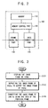
- FIG. 3 is a flowchart illustrating an exemplary embodiment of a method for driving the data processing part of FIG. 2 .
- the data processing part 100 includes a memory 110, a memory control part 120, a frame doubling part 130 and a data correcting part 170.
- the memory 110 stores the image frame data of 120 Hz (step S121 in FIG. 3 ).
- the memory 110 is an external memory.
- the memory 110 is a synchronous DRAM ("SDRAM").
- the memory control part 120 controls writing and reading of data in the memory 110. This control is performed for processing the data of the frame doubling part 130 and the data correcting part 170.
- the frame doubling part 130 repeats the image frame data of 120 Hz using the memory 110 in order to output the image frame of 240 Hz (step S 122 in FIG.3 ).
- the frame doubling part 130 repeats a left-eye image frame data and a right-eye image frame data, both at 120 Hz, in order to output a first left-eye image frame, a second left-eye image frame, a first right-eye image frame and a second right-eye image frame, all at 240 Hz.
- the frame doubling part 130 repeats an original image frame and an interpolation image frame, both at 120 Hz, in order to output a first original image frame, a second original image frame, a first interpolation image frame and a second interpolation image frame, all at240 Hz.
- the frame doubling part 130 repeats the image frames of 120 Hz in order to output the image frames of 240 Hz.
- the data correcting part 170 includes a look-up table ("LUT") that stores correction data of over-driving and under-driving as a table type.
- the data correcting part 170 outputs the correction data stored in the LUT corresponding to the present frame data and reference data, which is the previous frame data stored in the memory 110 (step S123 in FIG.3 ).
- the correction data is correction data for the present frame.
- the data correcting part 170 corrects the present frame data, including data of 240 Hz comprising of a first left-eye image frame, a second left-eye image frame, a first right-eye image frame and a second right-eye image frame.
- the data correcting part 170 corrects the present frame data based on the previous frame data stored in the memory 110.
- the data correcting part 170 corrects the present frame data, including data of 240 Hz comprising a first original image frame, a second original image frame, a first interpolation image frame and a second interpolation image frame.
- the data correcting part 170 corrects the present frame data based on the previous frame data stored in the memory 110.
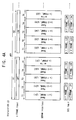
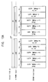
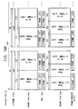
- FIGS. 4A and 4B are exemplary timing diagrams illustrating input and output signals of the data processing part of FIG. 2 .
- a horizontal axis (x-axis) indicates a time and a vertical axis (y-axis) indicates data in FIGS. 4A and 4B .
- the horizontal axis in FIG. 4B is extended from the horizontal axis in FIG. 4A .
- n is a natural number.
- the memory control part 120 controls writing and reading of the memory 110.
- the memory control part 120 writes the received data in the memory 110 and provides the read data, stored in the memory 110, to the frame doubling part 130 and the data correcting part 170.
- the memory control part 120 divides the first horizontal period H1 into 5 sub periods T1, T2, T3, T4, T5 and controls writing and reading of the memory 110 in each of the sub periods T1, T2, T3, T4, T5.
- the memory control part 120 reads first line data LD1 of an (n-1)-th image frame (n-1) FRAME in the memory 110 and provides the first line data LD1 of the (n-1)-th image frame (n-1) FRAME to the frame doubling part 130 and the data correcting part 170.
- the memory control part 120 reads first line data LD 1 of an (n-2)-th image frame (n-2) FRAME in the memory 110 and provides the first line data LD1 of the (n-2)-th image frame (n-2) FRAME to the data correcting part 170.
- the memory control part 120 reads second line data LD2 of the (n-1)-th image frame (n-1) FRAME in the memory 110 and provides the second line data LD2 of the (n-1)-th image frame (n-1) FRAME to the frame doubling part 130 and the data correcting part 170.
- the memory control part 120 reads second line data LD2 of the (n-2)-th image frame (n-2) FRAME in the memory 110 and provides the second line data LD2 of the (n-2)-th image frame (n-2) FRAME to the data correcting part 170.
- the memory control part 120 writes the first line data LD 1 of the n-th image frame n FRAME in the memory 110.
- the first line data LD1 of the n-th image frame n FRAME is buffered.
- the frame doubling part 130 receives the first line data LD1 and the second line data LD2 of the (n-1)-th image frame (n-1) FRAME received during the first sub period T1 and the third sub period T3. During the first horizontal period H1, the frame doubling part 130 outputs the first line data LD 1 and the second line data LD2 of the (n-1)-th image frame (n-1) FRAME.
- the data correcting part 170 corrects the first line data LD1 of the (n-1)-th frame (n-1) FRAME received during the first sub period T1 based on the first line data LD1 of the (n-2)-th frame (n-2) FRAME received during the second sub period T2.
- the data correcting part 170 corrects the second line data LD2 of the (n-1)-th frame (n-1) FRAME received during the third sub period T3 based on the second line data LD2 of the (n-2)-th frame (n-2) FRAME received during the fourth sub period T4.
- the data correcting part 170 corrects the first and second line data LD1 and LD2 of the (n-1)-th image frame (n-1) FRAME and outputs the corrected first and second line data LD1 and LD2 of the (n-1)-th image frame (n-1) FRAME during the first horizontal period H1.
- the data correcting part 170 corrects third and fourth line data LD3 and LD4 of the (n-1)-th image frame (n-1) FRAME and outputs the corrected third and fourth line data LD3 and LD4 of the (n-1)-th image frame (n-1) FRAME.
- the data correcting part 170 corrects 1119-th and 1120-th line data of the (n-1)-th image frame (n-1) FRAME and outputs the corrected 1119-th and 1120-th line data of the (n-1)-th image frame (n-1) FRAME.
- the data processing part 100 outputs the corrected (n-1)-th image frame (n-1) FRAME.
- the data processing part 100 outputs the (n-1)-th image frame (n-1) FRAME once more.
- the data processing part 100 outputs the corrected (n-1)-th image frame (n-1) FRAME twice during the n-th frame period n FP. Therefore, the data processing part 100 outputs the image frame data of 120 Hz into the image frame data of 240 Hz.
- FIG. 5 is a block diagram illustrating an exemplary embodiment of a data processing part according to the present invention.
- FIG. 6 is a flowchart illustrating an exemplary embodiment of a method for driving the data processing part of FIG. 5 .
- the data processing part 101 includes a memory 110, a memory control part 120, a frame doubling part 130, a compressing part 140 and a data correcting part 171.
- the memory 110 stores the image frame data of 120 Hz (step S 131 in FIG. 6 ).
- the memory 110 is an external memory.
- the memory 110 is SDRAM.
- the memory control part 120 controls writing and reading of data in the memory 110. This control is performed for processing data of the frame doubling part 130 and the data correcting part 171.
- the frame doubling part 130 repeats the image frame data of 120 Hz stored in the memory 110 to output the image frame data of 240 Hz (step S 132 in FIG. 6 ).
- the compressing part 140 compresses the image frame data of 240 Hz for storage in the memory 110 (step S133 in FIG. 6 ).
- the data compressed by the compressing part 140 is used as reference data in the data correcting part 171.
- a data loss due to a data compression has no effect on correction data generated by the data correcting part 171.
- a data rate of the memory 110 may be decreased by the data compression.
- the compressing part 140 compresses the image frame data bits by about 1/3 the data rate may be about 4/5 times lower than that of the non-compressed data in the previously described exemplary embodiment.
- the data correcting part 171 includes a LUT that stores correction data as a table type.
- the data correcting part 171 receives the previous frame compressed data stored in the memory 110 for correcting a present frame data received from the frame doubling part 130.
- the data correcting part 171 restores the compressed data into original data having original bits and then uses the restored data as reference data for the present frame data.
- the data correcting part 171 corrects the present frame data into correction data based on the restored data (step S134 in FIG. 6 ).
- the correction data is over-driven or under-driven present frame data and is stored in the LUT.
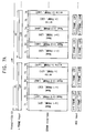
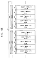
- FIGS. 7A and 7B are exemplary timing diagrams illustrating input and output signals of the data processing part of FIG. 5 .
- a horizontal axis (x-axis) indicates a time and a vertical axis (y-axis) indicates data in FIGS. 7A and 7B .
- the horizontal axis in FIG. 7B is extended from the horizontal axis in FIG. 7A .
- the n-th image frame is the image frame including data of 1120 horizontal lines.
- the memory control part 120 controls writing and reading of the memory 110.
- the memory control part 120 writes the received data in the memory 110 and provides the read data, stored in the memory 110, to the frame doubling part 130 and the data correcting part 171.
- the memory control part 120 divides the first horizontal period H1 into 6 sub periods T1, T2, T3, T4, T5, T6 and controls writing and reading of the memory 110 during each of the sub periods T1, T2, T3, T4, T5, T6.
- the memory control part 120 reads first line data LD1 of an (n-1)-th image frame (n-1) FRAME in the memory 110 and provides the first line data LD1 of the (n-1)-th image frame (n-1) FRAME to the frame doubling part 130 and the data correcting part 171.
- the memory control part 120 reads first line data Ldd1 of an (n-2)-th image frame (n-2) FRAME in the memory 110 and provides the first line data Ldd1 of the (n-2)-th image frame (n-2) FRAME to the data correcting part 171.
- the first line data Ldd1 is the compressed data.
- the memory control part 120 reads second line data LD2 of the (n-1)-th image frame (n-1) FRAME in the memory 110 and provides the second line data LD2 of the (n-1)-th image frame (n-1) FRAME to the frame doubling part 130 and the data correcting part 171.
- the memory control part 120 reads second line data Ldd2 of the (n-2)-th image frame (n-2) FRAME in the memory 110 and provides the second line data Ldd2 of the (n-2)-th image frame (n-2) FRAME to the data correcting part 170.
- the second line data Ldd2 is the compressed data.
- the memory control part 120 writes the first line data LD 1 of the n-th image frame n FRAME in the memory 110.
- the first line data LD1 of the n-th image frame n FRAME is buffered.
- the memory control part 120 writes the compressed first line data Ldd 1 of the n-th image frame n FRAME in the memory 110.
- the frame doubling part 130 receives the first line data LD1 and the second line data LD2 of the (n-1)-th image frame (n-1) FRAME.
- the frame doubling part 130 outputs the first line data LD1 and the second line data LD2 of the (n-1)-th image frame (n-1) FRAME.
- the data correcting part 171 restores the first line data Ldd1 of the (n-2)-th image frame (n-2) FRAME received during the second sub period T2 into original data.
- the data correcting part 171 corrects the first line data LD1 of the (n-1)-th frame received during the first sub period T1 based on the restored first line data of the (n-2)-th image frame (n-2) FRAME.
- the data correcting part 171 restores the second line data Ldd2 of the (n-2)-th image frame (n-2) FRAME received during the fourth sub period T4 into original data.
- the data correcting part 171 corrects the second line data LD2 of the (n-1)-th frame received during the third sub period T3 based on the restored second line data of the (n-2)-th image frame (n-2) FRAME.
- a bandwidth of each of the first, third and fifth sub periods, i.e. T1, T3 and T5 is different from that of each of the second, fourth and sixth sub periods, i.e. T2, T4 and T6, according to a compression rate as provided by the compression part 140.
- the data correcting part 171 corrects third and fourth line data LD3 and LD4 of the (n-1)-th image frame (n-1) FRAME and outputs the corrected third and fourth line data LD3 and LD4 of the (n-1)-th image frame (n-1) FRAME.
- the data correcting part 171 corrects 1119-th and 1120-th line data of the (n-1)-th image frame (n-1) FRAME and outputs the corrected 1119-th and 1120-th line data of the (n-1)-th image frame (n-1) FRAME.
- the data processing part 101 outputs the (n-1)-th image frame (n-1) FRAME.
- the data processing part 101 outputs the (n-1)-th image frame (n-1) FRAME once more.
- the data processing part 101 outputs the corrected (n-1)-th image frame (n-1) FRAME twice during the n-th frame period n FP. Therefore, the data processing part 101 outputs the image frame data of 120 Hz into the image frame data of 240 Hz.
- FIG. 8 is a block diagram illustrating an exemplary embodiment of a data processing part according to the present invention.
- FIG. 9 is a flowchart illustrating an exemplary embodiment of a method for driving the data processing part of FIG. 8 .
- the data processing part 102 includes a first memory 111, a memory control part 121, a frame doubling part 130, a second memory 150, a compressing/controlling part 160 and a data correcting part 171.
- the first memory 111 stores an image frame of 120 Hz (step S141 in FIG. 9 ).
- the first memory 111 is an external memory.
- the first memory 111 is SDRAM.
- the memory control part 121 controls writing and reading of data in the first memory 111.
- the control is performed for processing data of the frame doubling part 130.
- the frame doubling part 130 repeats the image frame data of 120 Hz stored in the first memory 111 in order to output the image frame of 240 Hz (step S 142 in FIG. 9 ).
- the second memory 150 stores the compressed image frame data of 240 Hz for processing data of the data correcting part 171.
- the second memory 150 is an embedded DRAM (eDRAM).
- the compressing/controlling part 160 compresses the image frame data of 240 Hz received from the frame doubling part 130 and stores the compressed image frame data in the second memory 150 (step S 143 in FIG. 9 ).
- the compressing/controlling part 160 controls writing and reading of data in the second memory 150.
- the control is performed for processing data of the data correcting part 171.
- the data correcting part 171 includes a LUT that stores correction data of over-driving and under-driving as a table type.
- the data correcting part 171 receives the previous frame compressed data from the second memory 150 for correcting the present frame data received from the frame doubling part 130.
- the data correcting part 171 restores the compressed data into original data and uses the restored data as a reference data for the present frame data.
- the data correcting part 171 corrects the present frame data into a correction data based on the restored data (step S144 in FIG. 9 ).
- the correction data is over-driven or under-driven present frame data and is stored in the LUT.
- the first memory 111 is used for processing data of the frame doubling part 130.
- a data rate of the first memory 111 is decreased.
- the second memory 150 stores the compressed data so that a size of the second memory 150 is decreased.
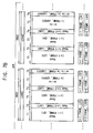
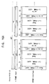
- FIGS. 10A and 10B are exemplary timing diagrams illustrating input and output signals of the data processing part of FIG. 8 .
- a horizontal axis (x-axis) indicates a time and a vertical axis (y-axis) indicates data in FIGS. 8A and 8B .
- the horizontal axis in FIG. 8B is extended from the horizontal axis in FIG. 8 .
- the memory control part 121 controls writing and reading of the first memory 111.
- the memory control part 121 writes the received data in the first memory 111 and provides the read data, stored in the first memory 111, to the frame doubling part 130.
- the memory control part 121 divides the first horizontal period H1 into 3 sub periods T11, T 12, T 13 and controls writing and reading of the first memory 111 during each of the sub periods T11, T12, T13.
- the memory control part 121 reads first line data LD1 of an (n-1)-th image frame (n-1) FRAME in the first memory 111 and provides the first line data LD1 of an (n-1)-th image frame (n-1) FRAME to the frame doubling part 130.
- the memory control part 121 reads second line data LD2 of an (n-2)-th image frame (n-2) FRAME in the first memory 111 and provides the second line data LD2 of an (n-2)-th image frame (n-2) FRAME to the frame doubling part 130.
- the memory control part 121 writes the first line data LD1 of the n-th image frame n FRAME in the first memory 111.
- the first line data LD1 of the n-th image frame n FRAME is buffered.
- the frame doubling part 130 receives the first line data LD1 and the second line data LD2 of the (n-1)-th image frame (n-1) FRAME.
- the frame doubling part 130 outputs the first line data LD1 and the second line data LD2 of the (n-1)-th image frame (n-1) FRAME.
- the compressing/controlling part 160 compresses the image frame data received from the frame doubling part 130. Thereafter, the compressing/controlling part 160 controls writing and reading of the second memory 150. In an exemplary embodiment, the compressing/controlling part 160 writes the compressed data to the second memory 150 and reads the compressed data from the second memory 150.
- the compressing/controlling part 160 divides the first horizontal period H1 into 4 sub periods T21, T22, T23, T24 and controls writing and reading of the second memory 150 during each of the sub periods sub periods T21, T22, T23, T24.
- the compressing/controlling part 160 reads first line data Ldd1 of an (n-2)-th image frame (n-2) FRAME in the second memory 150 and provides the first line data Ldd1 of the (n-2)-th image frame (n-2) FRAME to the data correcting part 171 during the first sub period T21.
- the first line data Ldd1 of the (n-2)-th image frame (n-2) FRAME is the compressed data.
- the compressing/controlling part 160 writes first line data Ldd1 of an (n-1)-th image frame (n-1) FRAME in the second memory 150.
- the first line data Ldd1 of the (n-1)-th image frame (n-1) FRAME is the compressed data.
- the compressing/controlling part 160 reads second line data Ldd2 of the (n-2)-th image frame (n-2) FRAME in the second memory 150 and provides the second line data Ldd2 of the (n-2)-th image frame (n-2) FRAME to the data correcting part 171 during the third sub period T23.
- the second line data Ldd2 of the (n-2)-th image frame (n-2) FRAME is the compressed data.
- the compressing/controlling part 160 writes second line data Ldd2 of the (n-1)-th image frame (n-1) FRAME in the second memory 150.
- the second line data Ldd2 of the (n-1)-th image frame (n-1) FRAME is the compressed data.
- the data correcting part 171 restores the first line data Ldd1 of the (n-2)-th image frame (n-2) FRAME, received during the first sub period T21, into original data.
- the data correcting part 171 corrects the first line data LD1 of the (n-1)-th image frame (n-1) FRAME based on the restored first line data of the (n-2)-th image frame (n-2) FRAME.
- the data correcting part 171 restores the second line data Ldd2 of the (n-2)-th image frame (n-2) FRAME, received during the third sub period T23, into original data.
- the data correcting part 171 corrects the second line data LD2 of the (n-1)-th image frame (n-1) FRAME based on the restored second line data of the (n-2)-th image frame (n-2) FRAME.
- the data correcting part 171 corrects third and fourth line data LD3 and LD4 of the (n-1)-th image frame (n-1) FRAME and outputs the corrected third and fourth line data LD3 and LD4 of the (n-1)-th image frame (n-1) FRAME.
- the data correcting part 171 corrects 1119-th and 1120-th line data of the (n-1)-th image frame (n-1) FRAME and outputs the corrected 1119-th and 1120-th line data of the (n-1)-th image frame (n-1) FRAME.
- the data processing part 102 outputs the (n-1)-th image frame (n-1) FRAME.
- the data processing part 102 outputs the (n-1)-th image frame (n-1) FRAME once more.
- the data processing part 102 outputs the corrected (n-1)-th image frame (n-1) FRAME twice during the n-th frame period n FP. Therefore, the data processing part 102 outputs the image frame data of 120 Hz into the image frame data of 240 Hz.
- FIG. 11 is a block diagram illustrating an exemplary embodiment of a data processing part according to the present invention.
- FIG. 12 is a flowchart illustrating an exemplary embodiment of a method for driving the data processing part of FIG. 11 .
- the data processing part 200 includes a memory 210, a memory control part 220, a data correcting part 230 and a frame doubling part 270.
- the data processing part 200 receives the image frame data of 120 Hz.
- the memory 210 stores the received image frame data and the corrected image frame data corrected by the data correcting part 230.
- the memory 210 is an external memory.
- the memory 210 is SDRAM.
- the memory control part 220 controls writing and reading of data in the memory 210.
- the control is performed for processing data of the data correcting part 230 and the frame doubling part 270.
- the data correcting part 230 includes a LUT that stores correction data as a table type.
- the data correcting part 230 corrects the present frame data into a correction data based on the data stored in the memory 210 (step S 151 in FIG. 12 ).
- the correction data is over-driven or under-driven present frame data and is stored in the LUT.
- the data correcting part 230 stores the corrected image frame data in the memory 210 (step S 152 in FIG. 12 ).
- the frame doubling part 270 repeats the corrected data received from the data correcting part 230 using the memory 210 and outputs the image frame data of 240 Hz (step S153 in FIG. 12 ).
- the data correcting part 230 corrects a left-eye image frame data (or a right-eye image frame data) of 120 Hz based on a previous right-eye image frame data (or a left-eye image frame data) stored in the memory 210.
- the data correcting part 230 outputs the corrected left-eye image frame data and the corrected right-eye image frame data, both at 120 Hz.
- the frame doubling part 270 repeats the corrected left-eye image frame data (or the corrected right-eye image frame data) of 120 Hz using the memory 210 to generate the corrected image frames data of 240 Hz.
- the frame doubling part 270 outputs at 240 Hz the corrected first left-eye image frame data, second left-eye image frame data, first right-eye image frame data and second right-eye image frame data.
- the data correcting part 230 corrects an original image frame data (or an interpolation image frame data) of 120 Hz based on a previous image frame interpolation data (or an original image frame data) stored in the memory 210.
- the data correcting part 230 outputs the corrected original image frame data and the corrected interpolation image frame, data both at 120 Hz.
- the frame doubling part 270 repeats the corrected original image frame data (or the corrected interpolation image frame data) of 120 Hz using the memory 210 in order to generate the corrected image frames data of 240 Hz.
- the frame doubling part 270 outputs at 240 Hz the corrected first original image frame data, second original image frame data, first interpolation image frame data and second interpolation image frame data.
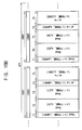
- FIGS. 13A and 13B are exemplary timing diagrams illustrating input and output signals of the data processing part of FIG. 11 .
- a horizontal axis (x-axis) indicates a time and a vertical axis (y-axis) indicates data in FIGS. 13A and 13B .
- the horizontal axis in FIG. 13B is extended from the horizontal axis in FIG. 13A .
- the memory control part 220 controls writing and reading of the memory 210.
- the memory control part 220 writes the received data in the memory 210 and provides the read data, stored in the memory 210, to the data correcting part 230 and the frame doubling part 270.
- the memory control part 220 divides the first horizontal period H1 into 5 sub periods T1, T2, T3, T4, T5 and controls writing and reading of the memory 210 during each of the sub periods T1, T2, T3, T4, T5.
- the memory control part 220 reads first line data LD1 of an (n-1)-th image frame (n-1) FRAME in the memory 210 and provides the first line data LD 1 of the (n-1)-th image frame (n-1) FRAME to the data correcting part 230 during the first sub period T1.
- the memory control part 220 reads first line data cLD1 of the (n-1)-th image frame (n-1) FRAME in memory 210 and provides the first line data cLD1 of the (n-1)-th image frame (n-1) FRAME to the frame doubling part 270 during the second sub period T2.
- the first line data cLD1 of the (n-1)-th image frame (n-1) FRAME is the corrected data.
- the memory control part 220 reads second line data cLD2 of the (n-1)-th image frame (n-1) FRAME in memory 210 and provides the second line data cLD2 of the (n-1)-th image frame (n-1) FRAME to the frame doubling part 270 during the third sub period T3.
- the second line data cLD2 of the (n-1)-th image frame (n-1) FRAME is the corrected data.
- the memory control part 220 writes the first line data LD1 of the n-th image frame n FRAME in the memory 210.
- the first line data LD1 of the n-th image frame n FRAME is buffered.
- the memory control part 220 writes a first line data cLD1 of the n-th image frame n FRAME in the memory 210.
- the first line data cLD 1 of the n-th image frame n FRAME the corrected data.
- the data correcting part 230 corrects the first line data LD 1 of the n-th image frame n FRAME based on the first line data LD1 of the (n-1)-th image frame (n-1) FRAME received during the first sub period T1. During the fifth sub period T5, the data correcting part 230 writes the corrected first line data cLD1 of the n-th image frame n FRAME in the memory 210.
- the frame doubling part 270 receives the corrected first line data cLD1 and the corrected second line data cLD2 of the (n-1)-th image frame (n-1) FRAME.
- the frame doubling part 270 outputs the corrected first line data cLD1 and the corrected second line data cLD2 of the (n-1)-th image frame (n-1) FRAME.
- the frame doubling part 270 outputs the corrected third and fourth line data LD3 and LD4 of the (n-1)-th image frame (n-1) FRAME.
- the data correcting part 171 corrects 1119-th and 1120-th line data of the (n-1)-th image frame (n-1) FRAME and outputs the corrected 1119-th and 1120-th line data of the (n-1)-th image frame (n-1) FRAME.
- the data processing part 200 outputs the (n-1)-th image frame (n-1) FRAME.
- the frame doubling part 270 outputs the corrected (n-1)-th image frame (n-1) FRAME once more.
- the data processing part 200 outputs the corrected (n-1)-th image frame (n-1) FRAME twice during the n-th frame period n FP. Therefore, the data processing part 200 outputs the image frame data of 120 Hz into the image frame data of 240 Hz.
- FIG. 14 is a block diagram illustrating an exemplary embodiment of a data processing part according to the present invention.
- FIG. 15 is a flowchart illustrating an exemplary embodiment of a method for driving the data processing part of FIG. 14 .
- the data processing part 201 includes a memory 210, a memory control part 220, a compressing part 240, a data correcting part 231 and a frame doubling part 270.
- the data processing part 201 receives an image frame data of 120 Hz.
- the memory 210 stores the compressed data compressed by the compressing part 240 and the corrected data corrected by the data correcting part 231.
- the memory 210 is an external memory.
- the memory 110 is SDRAM.
- the memory control part 220 controls writing and reading of data in the memory 210.
- the control is performed for processing data of the data correcting part 231 and the frame doubling part 270.
- the compressing part 240 compresses the image frame data, which, in an exemplary embodiment, is a reference data for use in the data correcting part 231, and stores the compressed data in the memory 210 (step S161 in FIG. 15 ).
- a data loss due to a data compression has minimal effect on correction data generated by the data correcting part 231.
- a data rate of the memory 210 is decreased by the data compression.
- the data correcting part 231 includes a LUT that stores correction data as a table type and restores the compressed data into original data.
- the data correcting part 231 receives the previous frame compressed data stored in the memory 210 for correcting the present frame data.
- the data correcting part 231 restores the compressed data into the original data and uses the restored data as a reference data for the present frame data.
- the data correcting part 231 corrects the present frame data into a correction data based on the restored previous frame data (step S162 in FIG. 15 ).
- the correction data is over-driven or under-driven present frame data and is stored in the LUT.
- the frame doubling part 270 repeats the image frame data of 120 Hz corrected by the data correcting part 231 in order to generate the image frame data of 240 Hz using the memory 210 (step S 163 in FIG. 15 ).
- FIGS. 16A and 16B are exemplary timing diagrams illustrating input and output signals of the data processing part of FIG. 14 .
- a horizontal axis (x-axis) indicates a time and a vertical axis (y-axis) indicates data in FIGS. 16A and 16B .
- the horizontal axis in FIG. 16B is extended from the horizontal axis in FIG. 16A .
- the memory control part 220 controls writing and reading of the memory 210.
- the memory control part 220 writes the compressed data in the memory 210 and provides the read data, stored in the memory 210, to the data correcting part 231 and the frame doubling part 270.
- the memory control part 220 divides the first horizontal period H1 into 5 sub periods T1, T2, T3, T4, T5 and controls writing and reading of the memory 210 during each of the sub periods T1, T2, T3, T4, T5.
- the memory control part 220 reads first line data Ldd1 of an (n-1)-th image frame (n-1) FRAME in the memory 210 and provides the first line data Ldd1 of the (n-1)-th image frame (n-1) FRAME to the data correcting part 231 during the first sub period T1.
- the first line data Ldd1 of the (n-1)-th image frame (n-1) FRAME is the compressed data.
- the memory control part 220 reads first line data cLD1 of the (n-1)-th image frame (n-1) FRAME in memory 210 and provides the first line data cLD1 of the (n-1)-th image frame (n-1) FRAME to the frame doubling part 270 during the second sub period T2.
- the first line data cLD1 of the (n-1)-th image frame (n-1) FRAME is the corrected data.
- the memory control part 220 reads second line data cLD2 of the (n-1)-th image frame (n-1) FRAME in memory 210 and provides the second line data cLD2 of the (n-1)-th image frame (n-1) FRAME to the frame doubling part 270 during the third sub period T3.
- the second line data cLD2 of the (n-1)-th image frame (n-1) FRAME is the corrected data.
- the memory control part 220 writes the first line data Ldd1 of the n-th image frame n FRAME in the memory 210.
- the first line data Ldd1 of the n-th image frame n FRAME is the compressed data.
- the memory control part 220 writes first line data cLD1 of the n-th image frame n FRAME in the memory 210.
- the first line data cLD1 of the n-th image frame n FRAME is the corrected data.
- the data correcting part 231 restores the first line data Ldd1 of the (n-1)-th image frame (n-1) FRAME received during the first sub period T1 into original data.
- the data correcting part 231 corrects the first line data LD1 of the n-th image frame n FRAME based on the restored first line data of the (n-1)-th image frame (n-1) FRAME.
- the data correcting part 231 writes the corrected first line data cLD1 of the n-th image frame n FRAME in the memory 210.
- the frame doubling part 270 receives the corrected first line data cLD1 and second line data cLD2 of the (n-1)-th image frame (n-1) FRAME.
- the frame doubling part 270 outputs the corrected first line data cLD1 and second line data cLD2 of the (n-1)-th image frame (n-1) FRAME.
- the frame doubling part 270 outputs the corrected third and fourth line data cLD3 and cLD4 of the (n-1)-th image frame (n-1) FRAME.
- the data correcting part 171 corrects 1119-th and 1120-th line data of the (n-1)-th image frame (n-1) FRAME and outputs the corrected 1119-th and 1120-th line data of the (n-1)-th image frame (n-1) FRAME.
- the data processing part 201 outputs the (n-1)-th image frame (n-1) FRAME.
- the data processing part 201 outputs the corrected (n-1)-th image frame (n-1) FRAME once more.
- the data processing part 201 outputs the corrected (n-1)-th image frame (n-1) FRAME twice during the n-th frame period n FP. Therefore, the data processing part 200 outputs the image frame data of 120 Hz into the image frame data of 240 Hz.
- FIG. 17 is a block diagram illustrating an exemplary embodiment of a data processing part according to the present invention.
- FIG. 18 is a flowchart illustrating an exemplary embodiment of a method for driving the data processing part of FIG. 17 .
- the data processing part 202 includes a first memory 211, a compressing/controlling part 221, a data correcting part 231, a second memory 250, a memory control part 260 and a frame doubling part 270.
- the data processing part 202 receives the image frame data of 120 Hz.
- the first memory 211 stores the compressed image frame data of 120 Hz (step S 171 in FIG. 18 ).
- the first memory 211 is eDRAM.
- the compressing/controlling part 221 compresses the image frame data and stores the compressed data in the first memory 211.
- the compressing/controlling part 221 controls writing and reading of the first memory 211.
- the control is performed for processing data of the data correcting part 231.
- the data correcting part 231 includes a LUT that stores correction data as a table type and restores the compressed data into original data.
- the data correcting part 231 receives the previous frame compressed data stored in the first memory 211 for correcting the present frame data.
- the data correcting part 231 restores the compressed data into original data and uses the restored data as a reference data for the present frame data.
- the data correcting part 231 corrects the present frame data into a correction data based on the restored data (step S172 in FIG. 18 ).
- the correction data is over-driven or under-driven present frame data and is stored in the LUT.
- the second memory 250 stores the corrected image frame data (step S173 in FIG. 18 ).
- the memory control part 260 controls writing and reading of the second memory 250 for processing data of the frame doubling part 270.
- the frame doubling part 270 repeats the corrected image frame of 120 Hz stored in the second memory 250 to output the image frame of 240 Hz (step S 174 in FIG. 18 ).
- FIGS. 19A and 19B are exemplary timing diagrams illustrating input and output signals of the data processing part of FIG. 17 .
- a horizontal axis (x-axis) indicates a time and a vertical axis (y-axis) indicates data in FIGS. 19A and 19B .
- the horizontal axis in FIG. 19B is extended from the horizontal axis in FIG. 19A .
- the compressing/controlling part 221 controls writing and reading of the first memory 211.
- the memory control part 221 writes the received data in the first memory 211 and provides the read data, stored in the first memory 211, to the data correcting part 231.
- the memory control part 220 divides the first horizontal period H1 into 2 sub periods T11, T12 and controls writing and reading of the first memory 211 during each of the sub periods T11, T12.
- the compressing/controlling part 221 reads a first line data Ldd1 of an (n-1)-th image frame (n-1) FRAME in the first memory 211 and provides the first line data Ldd1 of the (n-1)-th image frame (n-1) FRAME to the data correcting part 231 during a first sub period T11.
- the first line data Ldd1 of the (n-1)-th image frame (n-1) FRAME is the compressed data.
- the compressing/controlling part 221 writes a first line data Ldd1 of an n-th image frame n FRAME in the first memory 211.
- the first line data Ldd1 of the n-th image frame n FRAME is the compressed data.
- the data correcting part 231 restores the first line data Ldd1 of the (n-1)-th image frame (n-1) FRAME into original data.
- the data correcting part 231 corrects a first line data LD1 of an n-th image frame n FRAME based on the restored first line data of the (n-1)-th image frame (n-1) FRAME.
- the data correcting part 231 outputs the corrected first line data cLD 1 of the n-th image frame n FRAME.
- the memory control part 260 controls writing and reading of the second memory 250.
- the memory control part 260 writes the corrected data to the second memory 250 and reads the corrected data from the second memory 250.
- the memory control part 260 divides the first horizontal period H1 into 3 sub periods T21, T22, T23 and controls writing and reading of the second memory 250 during each of the sub periods T21, T22, T23.
- the memory control part 260 reads first line data cLD1 of an (n-1)-th image frame (n-1) FRAME in the memory 250 and provides the first line data cLD1 of the (n-1)-th image frame (n-1) FRAME to the frame doubling part 270 during the first sub period T21.
- the first line data cLD1 of the (n-1)-th image frame (n-1) FRAME is the corrected data.
- the memory control part 260 reads second line data cLD2 of the (n-1)-th image frame (n-1) FRAME in the second memory 250 and provides the second line data cLD2 of the (n-1)-th image frame n- FRAME to the frame doubling part 270 during second sub period T21.
- the second line data cLD2 of the (n-1)-th image frame (n-1) FRAME is the corrected data.
- the memory control part 260 writes a first line data cLD1 of an n-th image frame n FRAME in the second memory 250.
- the first line data cLD1 of the n-th image frame n FRAME is the corrected data.
- the frame doubling part 270 receives the corrected first line data cLD1 and the corrected second line data cLD2 of the (n-1)-th image frame (n-1) FRAME.
- the frame doubling part 270 outputs the corrected first and second line data cLD 1 and cLD2 of the (n-1)-th image frame (n-1) FRAME.
- the frame doubling part 270 outputs the corrected third and fourth line data cLD3 and cLD4 of the (n-1)-th image frame (n-1) FRAME.
- the data correcting part 171 corrects 1119-th and 1120-th line data of the (n-1)-th image frame (n-1) FRAME and outputs the corrected 1119-th and 1120-th line data of the (n-1)-th image frame (n-1) FRAME.
- the data processing part 202 outputs the (n-1)-th image frame (n-1) FRAME.
- the data processing part 202 outputs the corrected (n-1)-th image frame (n-1) FRAME once more.
- the data processing part 202 outputs the corrected (n-1)-th image frame (n-1) FRAME twice during the n-th frame period n FP. Therefore, the data processing part 200 outputs the image frame data of 120 Hz into the image frame data of 240 Hz.
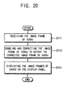
- FIG. 20 is a flowchart illustrating an exemplary embodiment of a method for displaying an image according to the present invention.
- the data processing part 100 receives an image frame data of 120 Hz (step S211 in FIG. 20 ).
- the data processing part 100 doubles and corrects the image frame data of 120 Hz to output the corrected image frame data of 240 Hz (step S213 in FIG. 20 ).
- the data processing part 100 is designed as any of the previously described exemplary embodiments.
- the data processing part 100 doubles and corrects a left-eye image frame data and a right-eye image frame data, both at 120 Hz, to generate a first left-eye image frame data, a second left-eye image frame data, a first right-eye image frame data and a second right-eye image frame data, all at 240 Hz.
- the data processing part 100 doubles and corrects an original image frame data and an interpolation image frame data, both at 120 Hz, processed via a motion estimation and motion compensation ("MEMC") technique in order to generate a first original image frame data, a second original image frame data, a first interpolation image frame data and a second interpolation image frame data, all at 240 Hz.
- MEMC motion estimation and motion compensation
- the panel control part 400 and the panel driving part 500 display the image frames data of 240 Hz received from the data processing part 100 on the display panel 700 (step S215 in FIG. 20 ).
- FIG. 21 is a flowchart illustrating an exemplary embodiment of a method for displaying an image according to the present invention.
- the data processing part 100 receives an image frame data of 120 Hz (step S221 in FIG. 21 ).
- the data processing part 100 doubles and corrects a left-eye image frame data and a right-eye image frame data, both at 120 Hz, to generate a first left-eye image frame data, a second left-eye image frame data, a first right-eye image frame data and a second right-eye image frame data, all at 240 Hz (step S223 in FIG. 21 ).
- the panel control part 400 and the panel driving part 500 display the first left-eye image frame data, the second left-eye image frame data, the first right-eye image frame data and the second right-eye image frame data, all at 240 Hz, received from the data processing part 100 on the display panel 700 (step S225 in FIG. 21 ).
- the display panel 700 displays the image frames data with a frame frequency of 240 Hz.
- the data processing part 100 is designed as any of the previously described exemplary embodiments.
- the data processing part 100 does not double an original image frame data and an interpolation image frame data, both at 120 Hz.
- the data processing part 100 corrects the original image frame data and the interpolation image frame data, both at 120 Hz, for over-driving or under-driving in order to output the corrected original and interpolation image frames data, all at 120 Hz (step S227 in FIG. 21 ).
- the panel control part 400 and the panel driving part 500 display the corrected original and interpolation image frames data, all at 120 Hz, received from the data processing part 100 on the display panel 700 (step S229 in FIG. 21 ).
- the display panel 700 displays the image frames data with a frame frequency of 120 Hz.
- FIG. 22 is a block diagram illustrating an exemplary embodiment of a display apparatus according the present invention.
- the display apparatus includes a data processing part 100, a black inserting part 300, a panel control part 400, a panel driving part 500 and a display panel 700.
- the data processing part 100 doubles and corrects an image frame data to generate a plurality of image frames data.
- the data processing part 100 is designed as any of the previously described exemplary embodiments.
- the black inserting part 300 inserts a black image frame data between a left-eye image frame data and a right-eye image frame data in the 3D image mode.
- the black inserting part 300 receives a first left-eye image frame data, a second left-eye image frame data, a first right-eye image frame data and a second right-eye image frame data, all at 240 Hz, and inserts the black image frame data between the first left-eye image frame data and the first right-eye image frame data.
- the black inserting part 300 outputs the first left-eye image frame data, a first black image frame data, the first right-eye image frame data and a second black image frame data, all at 240 Hz.
- the panel control part 400 provides image data and timing signals to the panel driving part 500.
- the panel driving part 500 includes a data driving part 510 and a gate driving part 520.
- the data driving part 510 converts image data of a digital signal received from the panel control part 400 to a data voltage of an analog signal and provides the data voltage to the display panel 700 based on a data timing signal received from the panel control part 400.
- the gate driving part 520 provides a gate signal to the display panel 700 based on a gate timing signal received from the panel control part 400.
- the display panel 700 includes a plurality of data lines, a plurality of gate lines crossing the data lines and a plurality of pixels.
- Each of the pixels includes a switching element connected to a data line, a gate line and a pixel electrode.
- the data voltages from the data driving part 510 are applied to data lines, and the gate signals from the gate driving part 520 are applied to the gate lines, so that the pixels display an image corresponding to the data voltages, respectively.
- FIG. 23 is a flowchart illustrating an exemplary embodiment of a method for displaying the image by the display apparatus of FIG. 22 .
- the data processing part 100 receives an image frame data of 120 Hz (step S231 in FIG. 23 ).
- the data processing part 100 doubles and corrects the image frame data of 120 Hz to output the image frame data of 240 Hz (step S233 in FIG. 23 ).
- the data processing part 100 is designed as any of the previously described exemplary embodiments.
- the data processing part 100 doubles and corrects a left-eye image frame data and a right-eye image frame data, both at 120 Hz, to generate a first left-eye image frame data, a second left-eye image frame data, a first right-eye image frame data and a second right-eye image frame data, all at 240 Hz.
- the data processing part 100 doubles and corrects an original image frame data and an interpolation image frame data, both at 120 Hz, processed via a MEMC technique in order to generate a first original image frame data, a second original image frame data, a first interpolation image frame data and a second interpolation image frame data, all at 240 Hz.
- the black inserting part 300 inserts the black image frame data between the left-eye image frame data and the right-eye image frame data in order to output the first left-eye image frame data, a first black image frame data, the first right-eye image frame data and a second black image frame data, all at 240 Hz (step S234 in FIG. 23 ).
- the black inserting part 300 bypasses the first original image frame data, the second original image frame data, the first interpolation image frame data and the second interpolation image frame data, all at 240 Hz.
- the panel control part 400 and the panel driving part 500 display the image frames data of 240 Hz received from the black inserting part 300 on the display panel 700 (step S235 in FIG. 23 ).
- the display panel 700 displays the image frames data with a frame frequency of 240 Hz.
- FIG. 24 is a flowchart illustrating an exemplary embodiment of a method for displaying an image according to the present invention.
- the data processing part 100 receives an image frame data of 120 Hz (step S241 in FIG. 24 ).
- the data processing part 100 doubles and corrects a left-eye image frame data and a right-eye image frame data, both at 120 Hz, in order to generate a first left-eye image frame data, a second left-eye image frame data, a first right-eye image frame data and a second right-eye image frame data, all at 240 Hz (step S243 in FIG. 24 ).
- the black inserting part 300 inserts the black image frame data between the left-eye image frame data and the right-eye image frame data to output the first left-eye image frame data, a first black image frame data, the first right-eye image frame data and a second black image frame data, all at 240 Hz (step S244 in FIG. 24 ).
- the panel control part 400 and the panel driving part 500 display the first left-eye image frame data, the first black image frame data, the first right-eye image frame data and the second black image frame data, all at 240 Hz, on the display panel 700 (step S245 in FIG. 24 ).
- the display panel 700 displays the image frames data with a frame frequency of 240 Hz.
- the data processing part 100 does not double an original image frame data and an interpolation image frame data, both at 120 Hz.
- the data processing part 100 corrects the original image frame data and the interpolation image frame data, both at 120 Hz, for over-driving or under-driving in order to output the corrected original and interpolation image frames data of 120 Hz (step S247 in FIG. 24 ).
- the panel control part 400 and the panel driving part 500 display the corrected original and interpolation image frames data, both at 120 Hz, received from the data processing part 100 on the display panel 700 (step S249 inn FIG. 24 ).
- the display panel 700 displays the image frames data with a frame frequency of 120 Hz.
- the received image frame data is repetitively generated by using the memory so that an image frame data of a frequency higher than a frequency of the received image frame is generated.
- a memory storing data of a previous frame data via DCC is used as the memory repetitively generating the image frame data. Therefore, in an exemplary embodiment, a FRC repetitively generating the image frame data is omitted so that a cost of production may be decreased.
Landscapes
- Engineering & Computer Science (AREA)
- Physics & Mathematics (AREA)
- Computer Hardware Design (AREA)
- General Physics & Mathematics (AREA)
- Theoretical Computer Science (AREA)
- Signal Processing (AREA)
- Multimedia (AREA)
- Control Of Indicators Other Than Cathode Ray Tubes (AREA)
- Liquid Crystal Display Device Control (AREA)
- Liquid Crystal (AREA)
- Testing, Inspecting, Measuring Of Stereoscopic Televisions And Televisions (AREA)
- Controls And Circuits For Display Device (AREA)
- Television Systems (AREA)
Abstract
Description
- Exemplary embodiments of the present invention relate to a method of processing image data, a method of displaying an image using the method of processing the image data and a display apparatus performing the method of displaying the image. More particularly, exemplary embodiments of the present invention relate to a method of processing high frequency image data, a method of displaying an image using the method of processing the high frequency image data and a display apparatus performing the method of displaying the image.
- Generally, a liquid crystal display ("LCD") device displays two-dimensional ("2D") images. Recently however, LCD devices capable of displaying three-dimensional ("3D") stereoscopic images have been developed in order to meet an increasing demand in fields, such as video games, movies, multimedia and other display fields.
- Generally, as human eyes see the world from slightly different locations, the images sensed by the eyes are slightly different. This difference in the sensed images is called binocular parallax. Through this natural phenomenon, a user of a stereoscopic image display device is able to view a 3D image.
- Generally, a stereoscopic image may be displayed via a shutter-glasses technique or an auto-stereoscopic technique. Typical shutter-glasses techniques include an anaglyph technique, a liquid crystal ("LC") shutter-glasses technique and other various techniques. In the typical implementation of the anaglyph technique, glasses with blue and red color filters, one color for each eye, are worn by a viewer during a viewing of the stereoscopic image. In the typical implementation of the LC shutter-glasses technique, a left image and a right image are alternated rapidly between a left LC shutter glass and a right LC shutter glass, each shutter being synchronized to obstruct the undesired image and transmit the desired image. Thus, each eye sees only its appropriate perspective view i.e., the left eye sees only the left view and the right eye only the right view.
- Generally, the LCD employed in the LC shutter-glasses technique is refreshed at a frequency of 240 Hz. Accordingly, the LCD typically uses a frame rate controller ("FRC"), which often is expensive, for displaying image frames with a frequency of 240 Hz. Therefore, the cost of producing the LCD employed in the LC shutter-glasses technique is often higher than that of producing an LCD that displays the 2D image typically refreshed at a frequency of 120 Hz.
- Exemplary embodiments of the present invention provide a method of processing image data in a more cost-effective way.
- Exemplary embodiments of the present invention also provide a method of displaying an image using the above-mentioned image data processing method.
- Exemplary embodiments of the present invention also provide a display apparatus which performs the above-mentioned method of displaying the image.
- According to an exemplary embodiment of the present invention, a method of processing image data is provided. In the method, the image frame data is stored in a first memory and repetitively read to output high frequency image frame data, which is corrected based on previous frame data.
- According to another exemplary embodiment of the present invention, there is provided a method of processing image data. In the method, the image frame data is corrected based on previous frame data and stored in a first memory, which is repetitively read to output high frequency image frame data.
- According to still another exemplary embodiment of the present invention, there is provided a method of displaying an image. In the method, left-eye image data or right-eye image data are stored in a memory. The left-eye image data or the right-eye image data are doubled and corrected by controlling the memory to generate a first and a second left-eye high frequency image frames or a first and a second right-eye high frequency image frames. The high frequency image frames are displayed on a display panel.
- According to still another exemplary embodiment of the present invention, a display apparatus includes a display panel, a data processing part and a panel driving part. The display panel displays an image. The data processing part doubles and corrects image frame data stored in a memory to generate high frequency image frame data. The panel driving part displays the high frequency image frames on the display panel based on the high frequency image frame data.
- In an exemplary embodiment, the display apparatus may further include a black inserting part which inserts a black image frame between a left-eye image frame and a right-eye image frame. The panel driving part may display the left-eye image frame, the black image frame, the right-eye image frame and another black image frame.
- In an exemplary embodiment, the data processing part may include a first memory, a frame doubling part and a data correcting part. The first memory may store the image frame data. The frame doubling part may repetitively read the image frame data stored in the first memory to output the high frequency image frame data. The data correcting part may correct the high frequency image frame data based on previous frame data.
- In an exemplary embodiment, the data processing part may include a data correcting part, a first memory and a frame doubling part. The data correcting part may correct the high frequency image frame data based on previous frame data. The first memory may store the corrected image frame data. The frame doubling part may repetitively read the image frame data stored in the first memory to output the high frequency image frame data.
- According to an exemplary embodiment of the present invention, the received low frequency image frame may be repetitively generated by using a memory for correcting data or a special memory so that a higher frequency image frame may be generated.
- The above and other features and advantages of the present invention will become more apparent by describing in detailed exemplary embodiments thereof with reference to the accompanying drawings, in which:
-
FIG. 1 is a block diagram illustrating exemplary embodiment of a display apparatus according to the present invention; -
FIG. 2 is a block diagram illustrating exemplary embodiment of a data processing part ofFIG. 1 ; -
FIG. 3 is a flowchart illustrating an exemplary embodiment of a method for driving the data processing part ofFIG. 2 ; -
FIGS. 4A and4B are exemplary timing diagrams illustrating input and output signals of the data processing part ofFIG. 2 ; -
FIG. 5 is a block diagram illustrating exemplary embodiment of a data processing part according to the present invention; -
FIG. 6 is a flowchart illustrating an exemplary embodiment of a method for driving the data processing part ofFIG. 5 ; -
FIGS. 7A and7B are exemplary timing diagrams illustrating input and output signals of the data processing part ofFIG. 5 ; -
FIG. 8 is a block diagram illustrating exemplary embodiment of a data processing part according to the present invention; -
FIG. 9 is a flowchart illustrating an exemplary embodiment of a method for driving the data processing part ofFIG. 8 ; -
FIGS. 10A and10B are exemplary timing diagrams illustrating input and output signals of the data processing part ofFIG. 8 ; -
FIG. 11 is a block diagram illustrating exemplary embodiment of a data processing part according to the present invention; -
FIG. 12 is a flowchart illustrating an exemplary embodiment of a method for driving the data processing part ofFIG. 11 ; -
FIGS. 13A and13B are exemplary timing diagrams illustrating input and output signals of the data processing part ofFIG. 11 ; -
FIG. 14 is a block diagram illustrating exemplary embodiment of a data processing part according to the present invention; -
FIG. 15 is a flowchart illustrating an exemplary embodiment of a method for driving the data processing part ofFIG. 14 ; -
FIGS. 16A and16B are exemplary timing diagrams illustrating input and output signals of the data processing part ofFIG. 14 ; -
FIG. 17 is a block diagram illustrating an exemplary embodiment of a data processing part according to the present invention; -
FIG. 18 is a flowchart illustrating an exemplary embodiment of a method for driving the data processing part ofFIG. 17 ; -
FIGS. 19A and19B are exemplary timing diagrams illustrating input and output signals of the data processing part ofFIG. 17 ; -
FIG. 20 is a flowchart illustrating an exemplary embodiment of a method for displaying an image according to the present invention; -
FIG. 21 is a flowchart illustrating an exemplary embodiment of a method for displaying an image according to the present invention; -
FIG. 22 is a block diagram illustrating an exemplary embodiment of a display apparatus according to the present invention; -
FIG. 23 is a flowchart illustrating an exemplary embodiment of a method for displaying the image by the display apparatus ofFIG. 22 ; and -
FIG. 24 is a flowchart illustrating an exemplary embodiment of a method for displaying an image according to the present invention. - The present invention is described more fully hereinafter with reference to the accompanying drawings, in which exemplary embodiments of the present invention are shown. The present invention may, however, be embodied in many different forms and should not be construed as limited to the exemplary embodiments set forth herein. Rather, these exemplary embodiments are provided so that this disclosure will be thorough and complete, and will fully convey the scope of the present invention to those skilled in the art. Like reference numerals refer to like elements throughout.
- It will be understood that when an element is referred to as being "on" another element, it can be directly on the other element or intervening elements may be present therebetween. In contrast, when an element is referred to as being "directly on" another element, there are no intervening elements present. As used herein, the term "and/or" includes any and all combinations of one or more of the associated listed items.
- It will be understood that, although the terms first, second, third etc. may be used herein to describe various elements, components, regions, layers and/or sections, these elements, components, regions, layers and/or sections should not be limited by these terms. These terms are only used to distinguish one element, component, region, layer or section from another region, layer or section. Thus, a first element, component, region, layer or section discussed below could be termed a second element, component, region, layer or section without departing from the teachings of the present invention.
- Spatially relative terms, such as "beneath," "below," "lower," "above," "upper" and the like, may be used herein for ease of description to describe one element or feature's relationship to another element(s) or feature(s) as illustrated in the figures. It will be understood that the spatially relative terms are intended to encompass different orientations of the device in use or operation in addition to the orientation depicted in the figures. For example, if the device in the figures is turned over, elements described as "below" or "beneath" other elements or features would then be oriented "above" the other elements or features. Thus, the exemplary term "below" can encompass both an orientation of above and below. The device may be otherwise oriented (rotated 90 degrees or at other orientations) and the spatially relative descriptors used herein interpreted accordingly.
- The terminology used herein is for the purpose of describing particular example embodiments only and is not intended to be limiting of the present invention. As used herein, the singular forms "a," "an" and "the" are intended to include the plural forms as well, unless the context clearly indicates otherwise. It will be further understood that the terms "comprises" and/or "comprising," when used in this specification, specify the presence of stated features, integers, steps, operations, elements, and/or components, but do not preclude the presence or addition of one or more other features, integers, steps, operations, elements, components, and/or groups thereof.
- Exemplary embodiments of the invention are described herein with reference to cross-sectional illustrations that are schematic illustrations of idealized example embodiments (and intermediate structures) of the present invention. As such, variations from the shapes of the illustrations as a result, for example, of manufacturing techniques and/or tolerances, are to be expected. Thus, example embodiments of the present invention should not be construed as limited to the particular shapes of regions illustrated herein but are to include deviations in shapes that result, for example, from manufacturing. For example, an implanted region illustrated as a rectangle will, typically, have rounded or curved features and/or a gradient of implant concentration at its edges rather than a binary change from implanted to non-implanted region. Likewise, a buried region formed by implantation may result in some implantation in the region between the buried region and the surface through which the implantation takes place. Thus, the regions illustrated in the figures are schematic in nature and their shapes are not intended to illustrate the actual shape of a region of a device and are not intended to limit the scope of the present invention.
- Unless otherwise defined, all terms (including technical and scientific terms) used herein have the same meaning as commonly understood by one of ordinary skill in the art to which this invention belongs. It will be further understood that terms, such as those defined in commonly used dictionaries, should be interpreted as having a meaning that is consistent with their meaning in the context of the relevant art and will not be interpreted in an idealized or overly formal sense unless expressly so defined herein.
- All methods described herein can be performed in a suitable order unless otherwise indicated herein or otherwise clearly contradicted by context. The use of any and all examples, or exemplary language (e.g., "such as"), is intended merely to better illustrate the invention and does not pose a limitation on the scope of the invention unless otherwise claimed. No language in the specification should be construed as indicating any non-claimed element as essential to the practice of the invention as used herein.
- Hereinafter, exemplary embodiments of the present invention will be explained in detail with reference to the accompanying drawings.
-
FIG. 1 is a block diagram illustrating an exemplary embodiment of a display apparatus according the present invention. - Referring to
FIG. 1 , the display apparatus includes adata processing part 100, apanel control part 400, apanel driving part 500 and adisplay panel 700. - The
data processing part 100 receives image frame data having a first frequency. Thedata processing part 100 then doubles the frequency of the image frame data and correspondingly corrects the image frame data. Thus, thedata processing part 100 outputs, to thepanel control part 400, the image frame data having a second frequency, which is two times higher than the first frequency. - The correction of the image frame data is performed in order to accommodate for over-driving or under-driving of the present frame data based on previous frame data. The correction method may include dynamic capacitance compensation ("DCC"), which is a technology typically used for decreasing an image distortion according to a temperature of a display panel in order to improve a response time of a LC.
- In an exemplary embodiment, the first frequency image frame is displayed with the first frequency on the
display panel 700. The second frequency image frame is displayed with the second frequency on thedisplay panel 700. Hereinafter, for clarity, the first frequency is referred to as 120 Hz and the second frequency is referred to as 240 Hz. - The
panel control part 400 provides thepanel driving part 500 with a timing signal and the image frame data - The
panel driving part 500 includes adata driving part 510 and agate driving part 520. In an exemplary embodiment, thedata driving part 510 converts image frame data of a digital signal received from thepanel control part 400 into a data voltage of an analog signal. Thedata driving part 510 then provides the data voltage to thedisplay panel 700 based on a data timing signal received from thepanel control part 400. Thegate driving part 520 generates a gate signal based on a gate timing signal received from thepanel control part 400 and provides the gate signal to thedisplay panel 700. - The
display panel 700 includes a plurality of data lines, a plurality of gate lines crossing the data lines and a plurality of pixels. Each of the pixels includes a switching element connected to a data line, a gate line and a pixel electrode. The data voltages from thedata driving part 510 are applied to data lines and the gate signals from thegate driving part 520 are applied to the gate lines so that the pixels display an image corresponding to the data voltages, respectively. -
FIG. 2 is a block diagram illustrating an exemplary embodiment of a data processing part ofFIG. 1 .FIG. 3 is a flowchart illustrating an exemplary embodiment of a method for driving the data processing part ofFIG. 2 . - Referring to
FIGS. 2 and 3 , thedata processing part 100 includes amemory 110, amemory control part 120, aframe doubling part 130 and adata correcting part 170. - The
memory 110 stores the image frame data of 120 Hz (step S121 inFIG. 3 ). In an exemplary embodiment, thememory 110 is an external memory. In an exemplary embodiment, thememory 110 is a synchronous DRAM ("SDRAM"). - The
memory control part 120 controls writing and reading of data in thememory 110. This control is performed for processing the data of theframe doubling part 130 and thedata correcting part 170. - The
frame doubling part 130 repeats the image frame data of 120 Hz using thememory 110 in order to output the image frame of 240 Hz (step S 122 inFIG.3 ). - In an exemplary embodiment, in a 3D image mode, the
frame doubling part 130 repeats a left-eye image frame data and a right-eye image frame data, both at 120 Hz, in order to output a first left-eye image frame, a second left-eye image frame, a first right-eye image frame and a second right-eye image frame, all at 240 Hz. In a 2D image mode, theframe doubling part 130 repeats an original image frame and an interpolation image frame, both at 120 Hz, in order to output a first original image frame, a second original image frame, a first interpolation image frame and a second interpolation image frame, all at240 Hz. In an exemplary embodiment, theframe doubling part 130 repeats the image frames of 120 Hz in order to output the image frames of 240 Hz. - The
data correcting part 170 includes a look-up table ("LUT") that stores correction data of over-driving and under-driving as a table type. Thedata correcting part 170 outputs the correction data stored in the LUT corresponding to the present frame data and reference data, which is the previous frame data stored in the memory 110 (step S123 inFIG.3 ). The correction data is correction data for the present frame. - In an exemplary embodiment, in the 3D image mode, the
data correcting part 170 corrects the present frame data, including data of 240 Hz comprising of a first left-eye image frame, a second left-eye image frame, a first right-eye image frame and a second right-eye image frame. Thedata correcting part 170 corrects the present frame data based on the previous frame data stored in thememory 110. - In an exemplary embodiment, in the 2D image mode, the
data correcting part 170 corrects the present frame data, including data of 240 Hz comprising a first original image frame, a second original image frame, a first interpolation image frame and a second interpolation image frame. Thedata correcting part 170 corrects the present frame data based on the previous frame data stored in thememory 110. -
FIGS. 4A and4B are exemplary timing diagrams illustrating input and output signals of the data processing part ofFIG. 2 . A horizontal axis (x-axis) indicates a time and a vertical axis (y-axis) indicates data inFIGS. 4A and4B . The horizontal axis inFIG. 4B is extended from the horizontal axis inFIG. 4A . - Referring to
FIGS. 2 and4A , subsequently explained is an operation of thedata processing part 100 when an n-th image frame n FRAME having data of 1120 horizontal lines is received. Herein, for clarity, n is a natural number. - The
memory control part 120 controls writing and reading of thememory 110. In an exemplary embodiment, thememory control part 120 writes the received data in thememory 110 and provides the read data, stored in thememory 110, to theframe doubling part 130 and thedata correcting part 170. - In an exemplary embodiment, during a first horizontal period H1 in which first line data LD1 of the n-th image frame n FRAME is input, the
memory control part 120 divides the first horizontal period H1 into 5 sub periods T1, T2, T3, T4, T5 and controls writing and reading of thememory 110 in each of the sub periods T1, T2, T3, T4, T5. - During the first sub period T1, the
memory control part 120 reads first line data LD1 of an (n-1)-th image frame (n-1) FRAME in thememory 110 and provides the first line data LD1 of the (n-1)-th image frame (n-1) FRAME to theframe doubling part 130 and thedata correcting part 170. - During the second sub period T2, the
memory control part 120 reads firstline data LD 1 of an (n-2)-th image frame (n-2) FRAME in thememory 110 and provides the first line data LD1 of the (n-2)-th image frame (n-2) FRAME to thedata correcting part 170. - During the third sub period T3, the
memory control part 120 reads second line data LD2 of the (n-1)-th image frame (n-1) FRAME in thememory 110 and provides the second line data LD2 of the (n-1)-th image frame (n-1) FRAME to theframe doubling part 130 and thedata correcting part 170. - During the fourth sub period T4, the
memory control part 120 reads second line data LD2 of the (n-2)-th image frame (n-2) FRAME in thememory 110 and provides the second line data LD2 of the (n-2)-th image frame (n-2) FRAME to thedata correcting part 170. - During the fifth sub period T5, the
memory control part 120 writes the firstline data LD 1 of the n-th image frame n FRAME in thememory 110. During the first to fourth sub periods T1 to T4, the first line data LD1 of the n-th image frame n FRAME is buffered. - The
frame doubling part 130 receives the first line data LD1 and the second line data LD2 of the (n-1)-th image frame (n-1) FRAME received during the first sub period T1 and the third sub period T3. During the first horizontal period H1, theframe doubling part 130 outputs the firstline data LD 1 and the second line data LD2 of the (n-1)-th image frame (n-1) FRAME. - The
data correcting part 170 corrects the first line data LD1 of the (n-1)-th frame (n-1) FRAME received during the first sub period T1 based on the first line data LD1 of the (n-2)-th frame (n-2) FRAME received during the second sub period T2. Thedata correcting part 170 corrects the second line data LD2 of the (n-1)-th frame (n-1) FRAME received during the third sub period T3 based on the second line data LD2 of the (n-2)-th frame (n-2) FRAME received during the fourth sub period T4. Thedata correcting part 170 corrects the first and second line data LD1 and LD2 of the (n-1)-th image frame (n-1) FRAME and outputs the corrected first and second line data LD1 and LD2 of the (n-1)-th image frame (n-1) FRAME during the first horizontal period H1. - As previously described, during a second horizontal period H2 in which the second line data LD2 of the n-th image frame n FRAME is received, the
data correcting part 170 corrects third and fourth line data LD3 and LD4 of the (n-1)-th image frame (n-1) FRAME and outputs the corrected third and fourth line data LD3 and LD4 of the (n-1)-th image frame (n-1) FRAME. - Therefore, in an exemplary embodiment, during a 560-th horizontal period in which 560-th line data corresponding to a middle of the n-th image frame n FRAME is input, the
data correcting part 170 corrects 1119-th and 1120-th line data of the (n-1)-th image frame (n-1) FRAME and outputs the corrected 1119-th and 1120-th line data of the (n-1)-th image frame (n-1) FRAME. In an exemplary embodiment, during a former half period of an n-th frame period n FP in which the n-th image frame n FRAME is input, thedata processing part 100 outputs the corrected (n-1)-th image frame (n-1) FRAME. - Referring to
FIG. 4B , during a latter half period of the n-th frame period n FP, thedata processing part 100 outputs the (n-1)-th image frame (n-1) FRAME once more. - Thus, the
data processing part 100 outputs the corrected (n-1)-th image frame (n-1) FRAME twice during the n-th frame period n FP. Therefore, thedata processing part 100 outputs the image frame data of 120 Hz into the image frame data of 240 Hz. - Hereinafter, for clarity, the same reference numerals will be used to refer to the same or like parts as those described in the previous exemplary embodiment and any repetitive detailed explanation will be omitted.
-
FIG. 5 is a block diagram illustrating an exemplary embodiment of a data processing part according to the present invention.FIG. 6 is a flowchart illustrating an exemplary embodiment of a method for driving the data processing part ofFIG. 5 . - Referring to
FIGS. 5 and6 , thedata processing part 101 includes amemory 110, amemory control part 120, aframe doubling part 130, a compressingpart 140 and adata correcting part 171. - The
memory 110 stores the image frame data of 120 Hz (step S 131 inFIG. 6 ). In an exemplary embodiment, thememory 110 is an external memory. In an exemplary embodiment, thememory 110 is SDRAM. - The
memory control part 120 controls writing and reading of data in thememory 110. This control is performed for processing data of theframe doubling part 130 and thedata correcting part 171. - The
frame doubling part 130 repeats the image frame data of 120 Hz stored in thememory 110 to output the image frame data of 240 Hz (step S 132 inFIG. 6 ). - The compressing
part 140 compresses the image frame data of 240 Hz for storage in the memory 110 (step S133 inFIG. 6 ). In an exemplary embodiment, the data compressed by the compressingpart 140 is used as reference data in thedata correcting part 171. In an exemplary embodiment, a data loss due to a data compression has no effect on correction data generated by thedata correcting part 171. However, a data rate of thememory 110 may be decreased by the data compression. In an exemplary embodiment, when the compressingpart 140 compresses the image frame data bits by about 1/3, the data rate may be about 4/5 times lower than that of the non-compressed data in the previously described exemplary embodiment. - In an exemplary embodiment, the
data correcting part 171 includes a LUT that stores correction data as a table type. Thedata correcting part 171 receives the previous frame compressed data stored in thememory 110 for correcting a present frame data received from theframe doubling part 130. Thedata correcting part 171 restores the compressed data into original data having original bits and then uses the restored data as reference data for the present frame data. Thedata correcting part 171 corrects the present frame data into correction data based on the restored data (step S134 inFIG. 6 ). In an exemplary embodiment, the correction data is over-driven or under-driven present frame data and is stored in the LUT. -
FIGS. 7A and7B are exemplary timing diagrams illustrating input and output signals of the data processing part ofFIG. 5 . A horizontal axis (x-axis) indicates a time and a vertical axis (y-axis) indicates data inFIGS. 7A and7B . The horizontal axis inFIG. 7B is extended from the horizontal axis inFIG. 7A . - Referring to
FIGS. 5 and7A , subsequently explained is an operation of thedata processing part 101 when an n-th image frame n FRAME is received. Here, for clarity, the n-th image frame is the image frame including data of 1120 horizontal lines. - The
memory control part 120 controls writing and reading of thememory 110. In an exemplary embodiment, thememory control part 120 writes the received data in thememory 110 and provides the read data, stored in thememory 110, to theframe doubling part 130 and thedata correcting part 171. - In an exemplary embodiment, during the first horizontal period H1 in which first line data LD1 of the n-th image frame n FRAME is received, the
memory control part 120 divides the first horizontal period H1 into 6 sub periods T1, T2, T3, T4, T5, T6 and controls writing and reading of thememory 110 during each of the sub periods T1, T2, T3, T4, T5, T6. - During the first sub period T1, the
memory control part 120 reads first line data LD1 of an (n-1)-th image frame (n-1) FRAME in thememory 110 and provides the first line data LD1 of the (n-1)-th image frame (n-1) FRAME to theframe doubling part 130 and thedata correcting part 171. - During the second sub period T2, the
memory control part 120 reads first line data Ldd1 of an (n-2)-th image frame (n-2) FRAME in thememory 110 and provides the first line data Ldd1 of the (n-2)-th image frame (n-2) FRAME to thedata correcting part 171. The first line data Ldd1 is the compressed data. - During the third sub period T3, the
memory control part 120 reads second line data LD2 of the (n-1)-th image frame (n-1) FRAME in thememory 110 and provides the second line data LD2 of the (n-1)-th image frame (n-1) FRAME to theframe doubling part 130 and thedata correcting part 171. - During the fourth sub period T4, the
memory control part 120 reads second line data Ldd2 of the (n-2)-th image frame (n-2) FRAME in thememory 110 and provides the second line data Ldd2 of the (n-2)-th image frame (n-2) FRAME to thedata correcting part 170. The second line data Ldd2 is the compressed data. - During the fifth sub period T5, the
memory control part 120 writes the firstline data LD 1 of the n-th image frame n FRAME in thememory 110. During the first to fourthsub periods T 1 to T4, the first line data LD1 of the n-th image frame n FRAME is buffered. - During the sixth sub period T6, the
memory control part 120 writes the compressed firstline data Ldd 1 of the n-th image frame n FRAME in thememory 110. - During the first sub period T1 and the third sub period T3, the
frame doubling part 130 receives the first line data LD1 and the second line data LD2 of the (n-1)-th image frame (n-1) FRAME. During the first horizontal period H1, theframe doubling part 130 outputs the first line data LD1 and the second line data LD2 of the (n-1)-th image frame (n-1) FRAME. - The
data correcting part 171 restores the first line data Ldd1 of the (n-2)-th image frame (n-2) FRAME received during the second sub period T2 into original data. Thedata correcting part 171 corrects the first line data LD1 of the (n-1)-th frame received during the first sub period T1 based on the restored first line data of the (n-2)-th image frame (n-2) FRAME. - The
data correcting part 171 restores the second line data Ldd2 of the (n-2)-th image frame (n-2) FRAME received during the fourth sub period T4 into original data. Thedata correcting part 171 corrects the second line data LD2 of the (n-1)-th frame received during the third sub period T3 based on the restored second line data of the (n-2)-th image frame (n-2) FRAME. - In an exemplary embodiment, a bandwidth of each of the first, third and fifth sub periods, i.e. T1, T3 and T5, is different from that of each of the second, fourth and sixth sub periods, i.e. T2, T4 and T6, according to a compression rate as provided by the
compression part 140. - As previously described, during a second horizontal period H2 in which the second line data LD2 of the n-th image frame n FRAME is received, the
data correcting part 171 corrects third and fourth line data LD3 and LD4 of the (n-1)-th image frame (n-1) FRAME and outputs the corrected third and fourth line data LD3 and LD4 of the (n-1)-th image frame (n-1) FRAME. - Therefore, in an exemplary embodiment, during a 560-th horizontal period corresponding to a middle of the image frame n FRAME in which 560-th line data is received, the
data correcting part 171 corrects 1119-th and 1120-th line data of the (n-1)-th image frame (n-1) FRAME and outputs the corrected 1119-th and 1120-th line data of the (n-1)-th image frame (n-1) FRAME. In an exemplary embodiment, during a former half period of an n-th frame period n FP, thedata processing part 101 outputs the (n-1)-th image frame (n-1) FRAME. - Referring to
FIG. 7B , during a latter half period of the n-th frame period n FP, thedata processing part 101 outputs the (n-1)-th image frame (n-1) FRAME once more. - Thus, the
data processing part 101 outputs the corrected (n-1)-th image frame (n-1) FRAME twice during the n-th frame period n FP. Therefore, thedata processing part 101 outputs the image frame data of 120 Hz into the image frame data of 240 Hz. -
FIG. 8 is a block diagram illustrating an exemplary embodiment of a data processing part according to the present invention.FIG. 9 is a flowchart illustrating an exemplary embodiment of a method for driving the data processing part ofFIG. 8 . - Referring to
FIGS. 8 and9 , thedata processing part 102 includes afirst memory 111, amemory control part 121, aframe doubling part 130, asecond memory 150, a compressing/controllingpart 160 and adata correcting part 171. - The
first memory 111 stores an image frame of 120 Hz (step S141 inFIG. 9 ). In an exemplary embodiment, thefirst memory 111 is an external memory. In an exemplary embodiment, thefirst memory 111 is SDRAM. - The
memory control part 121 controls writing and reading of data in thefirst memory 111. The control is performed for processing data of theframe doubling part 130. - The
frame doubling part 130 repeats the image frame data of 120 Hz stored in thefirst memory 111 in order to output the image frame of 240 Hz (step S 142 inFIG. 9 ). - The
second memory 150 stores the compressed image frame data of 240 Hz for processing data of thedata correcting part 171. In an exemplary embodiment, thesecond memory 150 is an embedded DRAM (eDRAM). - The compressing/controlling
part 160 compresses the image frame data of 240 Hz received from theframe doubling part 130 and stores the compressed image frame data in the second memory 150 (step S 143 inFIG. 9 ). The compressing/controllingpart 160 controls writing and reading of data in thesecond memory 150. The control is performed for processing data of thedata correcting part 171. - The
data correcting part 171 includes a LUT that stores correction data of over-driving and under-driving as a table type. Thedata correcting part 171 receives the previous frame compressed data from thesecond memory 150 for correcting the present frame data received from theframe doubling part 130. Thedata correcting part 171 restores the compressed data into original data and uses the restored data as a reference data for the present frame data. Thedata correcting part 171 corrects the present frame data into a correction data based on the restored data (step S144 inFIG. 9 ). In an exemplary embodiment, the correction data is over-driven or under-driven present frame data and is stored in the LUT. - In an exemplary embodiment, by using the
second memory 150 for processing data of thedata correcting part 171, thefirst memory 111 is used for processing data of theframe doubling part 130. Thus, a data rate of thefirst memory 111 is decreased. - In addition, in an exemplary embodiment, the
second memory 150 stores the compressed data so that a size of thesecond memory 150 is decreased. -
FIGS. 10A and10B are exemplary timing diagrams illustrating input and output signals of the data processing part ofFIG. 8 . A horizontal axis (x-axis) indicates a time and a vertical axis (y-axis) indicates data inFIGS. 8A and 8B . The horizontal axis inFIG. 8B is extended from the horizontal axis inFIG. 8 . - Referring to
FIGS. 8 and10A , subsequently explained is an operation of thedata processing part 102 when an n-th image frame n FRAME having data of 1120 horizontal lines is received. - The
memory control part 121 controls writing and reading of thefirst memory 111. In exemplary embodiment, thememory control part 121 writes the received data in thefirst memory 111 and provides the read data, stored in thefirst memory 111, to theframe doubling part 130. - In an exemplary embodiment, during a first horizontal period H1 in which first line data of the n-th image frame n FRAME is input, the
memory control part 121 divides the first horizontal period H1 into 3 sub periods T11, T 12, T 13 and controls writing and reading of thefirst memory 111 during each of the sub periods T11, T12, T13. - During the first sub period T11, the
memory control part 121 reads first line data LD1 of an (n-1)-th image frame (n-1) FRAME in thefirst memory 111 and provides the first line data LD1 of an (n-1)-th image frame (n-1) FRAME to theframe doubling part 130. - During the second sub period T12, the
memory control part 121 reads second line data LD2 of an (n-2)-th image frame (n-2) FRAME in thefirst memory 111 and provides the second line data LD2 of an (n-2)-th image frame (n-2) FRAME to theframe doubling part 130. - During the third sub period T13, the
memory control part 121 writes the first line data LD1 of the n-th image frame n FRAME in thefirst memory 111. During the first and second sub periods T11 and T12, the first line data LD1 of the n-th image frame n FRAME is buffered. - During the first sub period T11 and the second sub period T12, the
frame doubling part 130 receives the first line data LD1 and the second line data LD2 of the (n-1)-th image frame (n-1) FRAME. During the first horizontal period H1, theframe doubling part 130 outputs the first line data LD1 and the second line data LD2 of the (n-1)-th image frame (n-1) FRAME. - The compressing/controlling
part 160 compresses the image frame data received from theframe doubling part 130. Thereafter, the compressing/controllingpart 160 controls writing and reading of thesecond memory 150. In an exemplary embodiment, the compressing/controllingpart 160 writes the compressed data to thesecond memory 150 and reads the compressed data from thesecond memory 150. - In an exemplary embodiment, during a first horizontal period H1 in which first line data of the n-th image frame n FRAME is input, the compressing/controlling
part 160 divides the first horizontal period H1 into 4 sub periods T21, T22, T23, T24 and controls writing and reading of thesecond memory 150 during each of the sub periods sub periods T21, T22, T23, T24. - The compressing/controlling
part 160 reads first line data Ldd1 of an (n-2)-th image frame (n-2) FRAME in thesecond memory 150 and provides the first line data Ldd1 of the (n-2)-th image frame (n-2) FRAME to thedata correcting part 171 during the first sub period T21. The first line data Ldd1 of the (n-2)-th image frame (n-2) FRAME is the compressed data. - During the second sub period T22, the compressing/controlling
part 160 writes first line data Ldd1 of an (n-1)-th image frame (n-1) FRAME in thesecond memory 150. The first line data Ldd1 of the (n-1)-th image frame (n-1) FRAME is the compressed data. - The compressing/controlling
part 160 reads second line data Ldd2 of the (n-2)-th image frame (n-2) FRAME in thesecond memory 150 and provides the second line data Ldd2 of the (n-2)-th image frame (n-2) FRAME to thedata correcting part 171 during the third sub period T23. The second line data Ldd2 of the (n-2)-th image frame (n-2) FRAME is the compressed data. - During the fourth sub period T24, the compressing/controlling
part 160 writes second line data Ldd2 of the (n-1)-th image frame (n-1) FRAME in thesecond memory 150. The second line data Ldd2 of the (n-1)-th image frame (n-1) FRAME is the compressed data. - The
data correcting part 171 restores the first line data Ldd1 of the (n-2)-th image frame (n-2) FRAME, received during the first sub period T21, into original data. Thedata correcting part 171 corrects the first line data LD1 of the (n-1)-th image frame (n-1) FRAME based on the restored first line data of the (n-2)-th image frame (n-2) FRAME. - The
data correcting part 171 restores the second line data Ldd2 of the (n-2)-th image frame (n-2) FRAME, received during the third sub period T23, into original data. Thedata correcting part 171 corrects the second line data LD2 of the (n-1)-th image frame (n-1) FRAME based on the restored second line data of the (n-2)-th image frame (n-2) FRAME. - As previously described, during a second horizontal period H2 in which the second line data LD2 of the n-th image frame n FRAME is received, the
data correcting part 171 corrects third and fourth line data LD3 and LD4 of the (n-1)-th image frame (n-1) FRAME and outputs the corrected third and fourth line data LD3 and LD4 of the (n-1)-th image frame (n-1) FRAME. - Therefore, in an exemplary embodiment, during a 560-th horizontal period corresponding to a middle of the image frame n FRAME in which 560-th line data is received, the
data correcting part 171 corrects 1119-th and 1120-th line data of the (n-1)-th image frame (n-1) FRAME and outputs the corrected 1119-th and 1120-th line data of the (n-1)-th image frame (n-1) FRAME. In an exemplary embodiment, during a former half period of an n-th frame period n FP, thedata processing part 102 outputs the (n-1)-th image frame (n-1) FRAME. - Referring to
FIG. 10B , during a latter half period of the n-th frame period n FP, thedata processing part 102 outputs the (n-1)-th image frame (n-1) FRAME once more. - Thus, the
data processing part 102 outputs the corrected (n-1)-th image frame (n-1) FRAME twice during the n-th frame period n FP. Therefore, thedata processing part 102 outputs the image frame data of 120 Hz into the image frame data of 240 Hz. -
FIG. 11 is a block diagram illustrating an exemplary embodiment of a data processing part according to the present invention.FIG. 12 is a flowchart illustrating an exemplary embodiment of a method for driving the data processing part ofFIG. 11 . - Referring to
FIGS. 11 and 12 , thedata processing part 200 includes amemory 210, amemory control part 220, adata correcting part 230 and aframe doubling part 270. - The
data processing part 200 receives the image frame data of 120 Hz. - The
memory 210 stores the received image frame data and the corrected image frame data corrected by thedata correcting part 230. In an exemplary embodiment, thememory 210 is an external memory. In an exemplary embodiment, thememory 210 is SDRAM. - The
memory control part 220 controls writing and reading of data in thememory 210. The control is performed for processing data of thedata correcting part 230 and theframe doubling part 270. - The
data correcting part 230 includes a LUT that stores correction data as a table type. Thedata correcting part 230 corrects the present frame data into a correction data based on the data stored in the memory 210 (step S 151 inFIG. 12 ). In an exemplary embodiment, the correction data is over-driven or under-driven present frame data and is stored in the LUT. Thedata correcting part 230 stores the corrected image frame data in the memory 210 (step S 152 inFIG. 12 ). - The
frame doubling part 270 repeats the corrected data received from thedata correcting part 230 using thememory 210 and outputs the image frame data of 240 Hz (step S153 inFIG. 12 ). - In an exemplary embodiment, in the 3D image mode, the
data correcting part 230 corrects a left-eye image frame data (or a right-eye image frame data) of 120 Hz based on a previous right-eye image frame data (or a left-eye image frame data) stored in thememory 210. Thedata correcting part 230 outputs the corrected left-eye image frame data and the corrected right-eye image frame data, both at 120 Hz. Theframe doubling part 270 repeats the corrected left-eye image frame data (or the corrected right-eye image frame data) of 120 Hz using thememory 210 to generate the corrected image frames data of 240 Hz. In an exemplary embodiment, theframe doubling part 270 outputs at 240 Hz the corrected first left-eye image frame data, second left-eye image frame data, first right-eye image frame data and second right-eye image frame data. - In the 2D image mode, the
data correcting part 230 corrects an original image frame data (or an interpolation image frame data) of 120 Hz based on a previous image frame interpolation data (or an original image frame data) stored in thememory 210. Thedata correcting part 230 outputs the corrected original image frame data and the corrected interpolation image frame, data both at 120 Hz. Theframe doubling part 270 repeats the corrected original image frame data (or the corrected interpolation image frame data) of 120 Hz using thememory 210 in order to generate the corrected image frames data of 240 Hz. In an exemplary embodiment, theframe doubling part 270 outputs at 240 Hz the corrected first original image frame data, second original image frame data, first interpolation image frame data and second interpolation image frame data. -
FIGS. 13A and13B are exemplary timing diagrams illustrating input and output signals of the data processing part ofFIG. 11 . A horizontal axis (x-axis) indicates a time and a vertical axis (y-axis) indicates data inFIGS. 13A and13B . The horizontal axis inFIG. 13B is extended from the horizontal axis inFIG. 13A . - Referring to
FIGS. 11 and13A , subsequently described is an operation of thedata processing part 200 when an n-th image frame n FRAME having data of 1120 horizontal lines is received. - The
memory control part 220 controls writing and reading of thememory 210. In an exemplary embodiment, thememory control part 220 writes the received data in thememory 210 and provides the read data, stored in thememory 210, to thedata correcting part 230 and theframe doubling part 270. - In an exemplary embodiment, during a first horizontal period H1 in which first line data LD1 of the n-th image frame n FRAME is input, the
memory control part 220 divides the first horizontal period H1 into 5 sub periods T1, T2, T3, T4, T5 and controls writing and reading of thememory 210 during each of the sub periods T1, T2, T3, T4, T5. - The
memory control part 220 reads first line data LD1 of an (n-1)-th image frame (n-1) FRAME in thememory 210 and provides the firstline data LD 1 of the (n-1)-th image frame (n-1) FRAME to thedata correcting part 230 during the first sub period T1. - The
memory control part 220 reads first line data cLD1 of the (n-1)-th image frame (n-1) FRAME inmemory 210 and provides the first line data cLD1 of the (n-1)-th image frame (n-1) FRAME to theframe doubling part 270 during the second sub period T2. The first line data cLD1 of the (n-1)-th image frame (n-1) FRAME is the corrected data. - The
memory control part 220 reads second line data cLD2 of the (n-1)-th image frame (n-1) FRAME inmemory 210 and provides the second line data cLD2 of the (n-1)-th image frame (n-1) FRAME to theframe doubling part 270 during the third sub period T3. The second line data cLD2 of the (n-1)-th image frame (n-1) FRAME is the corrected data. - During the fourth sub period T4, the
memory control part 220 writes the first line data LD1 of the n-th image frame n FRAME in thememory 210. During the first to third sub periods T1 to T3, the first line data LD1 of the n-th image frame n FRAME is buffered. - During the fifth sub period T5, the
memory control part 220 writes a first line data cLD1 of the n-th image frame n FRAME in thememory 210. The firstline data cLD 1 of the n-th image frame n FRAME the corrected data. - The
data correcting part 230 corrects the firstline data LD 1 of the n-th image frame n FRAME based on the first line data LD1 of the (n-1)-th image frame (n-1) FRAME received during the first sub period T1. During the fifth sub period T5, thedata correcting part 230 writes the corrected first line data cLD1 of the n-th image frame n FRAME in thememory 210. - During the second sub period T2 and the third sub period T3, the
frame doubling part 270 receives the corrected first line data cLD1 and the corrected second line data cLD2 of the (n-1)-th image frame (n-1) FRAME. During the first horizontal period H1, theframe doubling part 270 outputs the corrected first line data cLD1 and the corrected second line data cLD2 of the (n-1)-th image frame (n-1) FRAME. - As previously described, during a second horizontal period H2 in which the second line data LD2 of the n-th image frame n FRAME is received, the
frame doubling part 270 outputs the corrected third and fourth line data LD3 and LD4 of the (n-1)-th image frame (n-1) FRAME. - Therefore, in an exemplary embodiment, during a 560-th horizontal period corresponding to a middle of the image frame n FRAME in which 560-th line data is received, the
data correcting part 171 corrects 1119-th and 1120-th line data of the (n-1)-th image frame (n-1) FRAME and outputs the corrected 1119-th and 1120-th line data of the (n-1)-th image frame (n-1) FRAME. In an exemplary embodiment, during a former half period of an n-th frame period n FP, thedata processing part 200 outputs the (n-1)-th image frame (n-1) FRAME. - Referring to
FIG. 13B , during a latter half period of the n-th frame period n FP, theframe doubling part 270 outputs the corrected (n-1)-th image frame (n-1) FRAME once more. - Thus, the
data processing part 200 outputs the corrected (n-1)-th image frame (n-1) FRAME twice during the n-th frame period n FP. Therefore, thedata processing part 200 outputs the image frame data of 120 Hz into the image frame data of 240 Hz. -
FIG. 14 is a block diagram illustrating an exemplary embodiment of a data processing part according to the present invention.FIG. 15 is a flowchart illustrating an exemplary embodiment of a method for driving the data processing part ofFIG. 14 . - Referring to
FIGS. 14 and 15 , thedata processing part 201 includes amemory 210, amemory control part 220, a compressingpart 240, adata correcting part 231 and aframe doubling part 270. - The
data processing part 201 receives an image frame data of 120 Hz. - The
memory 210 stores the compressed data compressed by the compressingpart 240 and the corrected data corrected by thedata correcting part 231. In an exemplary embodiment, thememory 210 is an external memory. In an exemplary embodiment, thememory 110 is SDRAM. - The
memory control part 220 controls writing and reading of data in thememory 210. The control is performed for processing data of thedata correcting part 231 and theframe doubling part 270. - The compressing
part 240 compresses the image frame data, which, in an exemplary embodiment, is a reference data for use in thedata correcting part 231, and stores the compressed data in the memory 210 (step S161 inFIG. 15 ). In an exemplary embodiment, a data loss due to a data compression has minimal effect on correction data generated by thedata correcting part 231. In an exemplary embodiment, a data rate of thememory 210 is decreased by the data compression. - The
data correcting part 231 includes a LUT that stores correction data as a table type and restores the compressed data into original data. Thedata correcting part 231 receives the previous frame compressed data stored in thememory 210 for correcting the present frame data. Thedata correcting part 231 restores the compressed data into the original data and uses the restored data as a reference data for the present frame data. Thedata correcting part 231 corrects the present frame data into a correction data based on the restored previous frame data (step S162 inFIG. 15 ). In an exemplary embodiment, the correction data is over-driven or under-driven present frame data and is stored in the LUT. - The
frame doubling part 270 repeats the image frame data of 120 Hz corrected by thedata correcting part 231 in order to generate the image frame data of 240 Hz using the memory 210 (step S 163 inFIG. 15 ). -
FIGS. 16A and16B are exemplary timing diagrams illustrating input and output signals of the data processing part ofFIG. 14 . A horizontal axis (x-axis) indicates a time and a vertical axis (y-axis) indicates data inFIGS. 16A and16B . The horizontal axis inFIG. 16B is extended from the horizontal axis inFIG. 16A . - Referring to
FIGS. 14 and16A , subsequently explained is an operation of thedata processing part 201 when an n-th image frame n FRAME having data of 1120 horizontal lines is received. - The
memory control part 220 controls writing and reading of thememory 210. In an exemplary embodiment, thememory control part 220 writes the compressed data in thememory 210 and provides the read data, stored in thememory 210, to thedata correcting part 231 and theframe doubling part 270. - In an exemplary embodiment, during a first horizontal period H1 in which first line data LD1 of the n-th image frame n FRAME is input, the
memory control part 220 divides the first horizontal period H1 into 5 sub periods T1, T2, T3, T4, T5 and controls writing and reading of thememory 210 during each of the sub periods T1, T2, T3, T4, T5. - The
memory control part 220 reads first line data Ldd1 of an (n-1)-th image frame (n-1) FRAME in thememory 210 and provides the first line data Ldd1 of the (n-1)-th image frame (n-1) FRAME to thedata correcting part 231 during the first sub period T1. The first line data Ldd1 of the (n-1)-th image frame (n-1) FRAME is the compressed data. - The
memory control part 220 reads first line data cLD1 of the (n-1)-th image frame (n-1) FRAME inmemory 210 and provides the first line data cLD1 of the (n-1)-th image frame (n-1) FRAME to theframe doubling part 270 during the second sub period T2. The first line data cLD1 of the (n-1)-th image frame (n-1) FRAME is the corrected data. - The
memory control part 220 reads second line data cLD2 of the (n-1)-th image frame (n-1) FRAME inmemory 210 and provides the second line data cLD2 of the (n-1)-th image frame (n-1) FRAME to theframe doubling part 270 during the third sub period T3. The second line data cLD2 of the (n-1)-th image frame (n-1) FRAME is the corrected data. - During the fourth sub period T4, the
memory control part 220 writes the first line data Ldd1 of the n-th image frame n FRAME in thememory 210. The first line data Ldd1 of the n-th image frame n FRAME is the compressed data. - During the fifth sub period T5, the
memory control part 220 writes first line data cLD1 of the n-th image frame n FRAME in thememory 210. The first line data cLD1 of the n-th image frame n FRAME is the corrected data. - The
data correcting part 231 restores the first line data Ldd1 of the (n-1)-th image frame (n-1) FRAME received during the first sub period T1 into original data. Thedata correcting part 231 corrects the first line data LD1 of the n-th image frame n FRAME based on the restored first line data of the (n-1)-th image frame (n-1) FRAME. During the fifth sub period T5, thedata correcting part 231 writes the corrected first line data cLD1 of the n-th image frame n FRAME in thememory 210. - During the second sub period T2 and the third sub period T3, the
frame doubling part 270 receives the corrected first line data cLD1 and second line data cLD2 of the (n-1)-th image frame (n-1) FRAME. During the first horizontal period H1, theframe doubling part 270 outputs the corrected first line data cLD1 and second line data cLD2 of the (n-1)-th image frame (n-1) FRAME. - As previously described, during a second horizontal period H2 in which the second line data LD2 of the n-th image frame n FRAME is received, the
frame doubling part 270 outputs the corrected third and fourth line data cLD3 and cLD4 of the (n-1)-th image frame (n-1) FRAME. - Therefore, in an exemplary embodiment, during a 560-th horizontal period corresponding to a middle of the image frame n FRAME in which 560-th line data is received, the
data correcting part 171 corrects 1119-th and 1120-th line data of the (n-1)-th image frame (n-1) FRAME and outputs the corrected 1119-th and 1120-th line data of the (n-1)-th image frame (n-1) FRAME. In an exemplary embodiment, during a former half period of an n-th frame period n FP, thedata processing part 201 outputs the (n-1)-th image frame (n-1) FRAME. - Referring to
FIG. 16B , during a latter half period of the n-th frame period n FP, thedata processing part 201 outputs the corrected (n-1)-th image frame (n-1) FRAME once more. - Thus, the
data processing part 201 outputs the corrected (n-1)-th image frame (n-1) FRAME twice during the n-th frame period n FP. Therefore, thedata processing part 200 outputs the image frame data of 120 Hz into the image frame data of 240 Hz. -
FIG. 17 is a block diagram illustrating an exemplary embodiment of a data processing part according to the present invention.FIG. 18 is a flowchart illustrating an exemplary embodiment of a method for driving the data processing part ofFIG. 17 . - Referring to
FIGS. 17 and18 , thedata processing part 202 includes afirst memory 211, a compressing/controllingpart 221, adata correcting part 231, asecond memory 250, amemory control part 260 and aframe doubling part 270. - The
data processing part 202 receives the image frame data of 120 Hz. - The
first memory 211 stores the compressed image frame data of 120 Hz (step S 171 inFIG. 18 ). In an exemplary embodiment, thefirst memory 211 is eDRAM. - The compressing/controlling
part 221 compresses the image frame data and stores the compressed data in thefirst memory 211. The compressing/controllingpart 221 controls writing and reading of thefirst memory 211. The control is performed for processing data of thedata correcting part 231. - The
data correcting part 231 includes a LUT that stores correction data as a table type and restores the compressed data into original data. Thedata correcting part 231 receives the previous frame compressed data stored in thefirst memory 211 for correcting the present frame data. Thedata correcting part 231 restores the compressed data into original data and uses the restored data as a reference data for the present frame data. Thedata correcting part 231 corrects the present frame data into a correction data based on the restored data (step S172 inFIG. 18 ). In an exemplary embodiment, the correction data is over-driven or under-driven present frame data and is stored in the LUT. - The
second memory 250 stores the corrected image frame data (step S173 inFIG. 18 ). - The
memory control part 260 controls writing and reading of thesecond memory 250 for processing data of theframe doubling part 270. - The
frame doubling part 270 repeats the corrected image frame of 120 Hz stored in thesecond memory 250 to output the image frame of 240 Hz (step S 174 inFIG. 18 ). -
FIGS. 19A and19B are exemplary timing diagrams illustrating input and output signals of the data processing part ofFIG. 17 . A horizontal axis (x-axis) indicates a time and a vertical axis (y-axis) indicates data inFIGS. 19A and19B . The horizontal axis inFIG. 19B is extended from the horizontal axis inFIG. 19A . - Referring to
FIGS. 17 and19A , subsequently explained is an operation of thedata processing part 202 when an n-th image frame n FRAME having data of 1120 horizontal lines is received. - The compressing/controlling
part 221 controls writing and reading of thefirst memory 211. In an exemplary embodiment, thememory control part 221 writes the received data in thefirst memory 211 and provides the read data, stored in thefirst memory 211, to thedata correcting part 231. - In an exemplary embodiment, during a first horizontal period H1 in which first line data LD1 of the n-th image frame n FRAME is input, the
memory control part 220 divides the first horizontal period H1 into 2 sub periods T11, T12 and controls writing and reading of thefirst memory 211 during each of the sub periods T11, T12. - The compressing/controlling
part 221 reads a first line data Ldd1 of an (n-1)-th image frame (n-1) FRAME in thefirst memory 211 and provides the first line data Ldd1 of the (n-1)-th image frame (n-1) FRAME to thedata correcting part 231 during a first sub period T11. The first line data Ldd1 of the (n-1)-th image frame (n-1) FRAME is the compressed data. - During a second sub period T12, the compressing/controlling
part 221 writes a first line data Ldd1 of an n-th image frame n FRAME in thefirst memory 211. The first line data Ldd1 of the n-th image frame n FRAME is the compressed data. - The
data correcting part 231 restores the first line data Ldd1 of the (n-1)-th image frame (n-1) FRAME into original data. Thedata correcting part 231 corrects a first line data LD1 of an n-th image frame n FRAME based on the restored first line data of the (n-1)-th image frame (n-1) FRAME. Thedata correcting part 231 outputs the corrected firstline data cLD 1 of the n-th image frame n FRAME. - The
memory control part 260 controls writing and reading of thesecond memory 250. In an exemplary embodiment, thememory control part 260 writes the corrected data to thesecond memory 250 and reads the corrected data from thesecond memory 250. - In an exemplary embodiment, during a first
horizontal period H 1 in which first line data of the n-th image frame n FRAME is input, thememory control part 260 divides the first horizontal period H1 into 3 sub periods T21, T22, T23 and controls writing and reading of thesecond memory 250 during each of the sub periods T21, T22, T23. - The
memory control part 260 reads first line data cLD1 of an (n-1)-th image frame (n-1) FRAME in thememory 250 and provides the first line data cLD1 of the (n-1)-th image frame (n-1) FRAME to theframe doubling part 270 during the first sub period T21. The first line data cLD1 of the (n-1)-th image frame (n-1) FRAME is the corrected data. - The
memory control part 260 reads second line data cLD2 of the (n-1)-th image frame (n-1) FRAME in thesecond memory 250 and provides the second line data cLD2 of the (n-1)-th image frame n- FRAME to theframe doubling part 270 during second sub period T21. The second line data cLD2 of the (n-1)-th image frame (n-1) FRAME is the corrected data. - During the third sub period T23, the
memory control part 260 writes a first line data cLD1 of an n-th image frame n FRAME in thesecond memory 250. The first line data cLD1 of the n-th image frame n FRAME is the corrected data. - During the first sub period T21 and the second sub period T22, the
frame doubling part 270 receives the corrected first line data cLD1 and the corrected second line data cLD2 of the (n-1)-th image frame (n-1) FRAME. During the first horizontal period H1, theframe doubling part 270 outputs the corrected first and secondline data cLD 1 and cLD2 of the (n-1)-th image frame (n-1) FRAME. - As previously described, during a second horizontal period H2 in which the second line data LD2 of the n-th image frame n FRAME is received, the
frame doubling part 270 outputs the corrected third and fourth line data cLD3 and cLD4 of the (n-1)-th image frame (n-1) FRAME. - Therefore, in an exemplary embodiment, during a 560-th horizontal period corresponding to a middle of the image frame n FRAME in which 560-th line data is received, the
data correcting part 171 corrects 1119-th and 1120-th line data of the (n-1)-th image frame (n-1) FRAME and outputs the corrected 1119-th and 1120-th line data of the (n-1)-th image frame (n-1) FRAME. In an exemplary embodiment, during a former half period of an n-th frame period n FP, thedata processing part 202 outputs the (n-1)-th image frame (n-1) FRAME. - Referring to
FIG. 19B , during a latter half period of the n-th frame period n FP, thedata processing part 202 outputs the corrected (n-1)-th image frame (n-1) FRAME once more. - Thus, the
data processing part 202 outputs the corrected (n-1)-th image frame (n-1) FRAME twice during the n-th frame period n FP. Therefore, thedata processing part 200 outputs the image frame data of 120 Hz into the image frame data of 240 Hz. -
FIG. 20 is a flowchart illustrating an exemplary embodiment of a method for displaying an image according to the present invention. - Referring to
FIGS. 1 and20 , thedata processing part 100 receives an image frame data of 120 Hz (step S211 inFIG. 20 ). Thedata processing part 100 doubles and corrects the image frame data of 120 Hz to output the corrected image frame data of 240 Hz (step S213 inFIG. 20 ). In an exemplary embodiment, thedata processing part 100 is designed as any of the previously described exemplary embodiments. - In an exemplary embodiment, in the 3D image mode, the
data processing part 100 doubles and corrects a left-eye image frame data and a right-eye image frame data, both at 120 Hz, to generate a first left-eye image frame data, a second left-eye image frame data, a first right-eye image frame data and a second right-eye image frame data, all at 240 Hz. In the 2D image mode, thedata processing part 100 doubles and corrects an original image frame data and an interpolation image frame data, both at 120 Hz, processed via a motion estimation and motion compensation ("MEMC") technique in order to generate a first original image frame data, a second original image frame data, a first interpolation image frame data and a second interpolation image frame data, all at 240 Hz. - The
panel control part 400 and thepanel driving part 500 display the image frames data of 240 Hz received from thedata processing part 100 on the display panel 700 (step S215 inFIG. 20 ). -
FIG. 21 is a flowchart illustrating an exemplary embodiment of a method for displaying an image according to the present invention. - Referring to
FIGS. 1 and21 , thedata processing part 100 receives an image frame data of 120 Hz (step S221 inFIG. 21 ). In the 3D image mode, thedata processing part 100 doubles and corrects a left-eye image frame data and a right-eye image frame data, both at 120 Hz, to generate a first left-eye image frame data, a second left-eye image frame data, a first right-eye image frame data and a second right-eye image frame data, all at 240 Hz (step S223 inFIG. 21 ). Thepanel control part 400 and thepanel driving part 500 display the first left-eye image frame data, the second left-eye image frame data, the first right-eye image frame data and the second right-eye image frame data, all at 240 Hz, received from thedata processing part 100 on the display panel 700 (step S225 inFIG. 21 ). Thedisplay panel 700 displays the image frames data with a frame frequency of 240 Hz. In an exemplary embodiment, thedata processing part 100 is designed as any of the previously described exemplary embodiments. - In the 2D image mode, the
data processing part 100 does not double an original image frame data and an interpolation image frame data, both at 120 Hz. In an exemplary embodiment, thedata processing part 100 corrects the original image frame data and the interpolation image frame data, both at 120 Hz, for over-driving or under-driving in order to output the corrected original and interpolation image frames data, all at 120 Hz (step S227 inFIG. 21 ). Thepanel control part 400 and thepanel driving part 500 display the corrected original and interpolation image frames data, all at 120 Hz, received from thedata processing part 100 on the display panel 700 (step S229 inFIG. 21 ). Thedisplay panel 700 displays the image frames data with a frame frequency of 120 Hz. -
FIG. 22 is a block diagram illustrating an exemplary embodiment of a display apparatus according the present invention. - Referring to
FIG. 22 , the display apparatus includes adata processing part 100, a black insertingpart 300, apanel control part 400, apanel driving part 500 and adisplay panel 700. - The
data processing part 100 doubles and corrects an image frame data to generate a plurality of image frames data. In an exemplary embodiment, thedata processing part 100 is designed as any of the previously described exemplary embodiments. - The black inserting
part 300 inserts a black image frame data between a left-eye image frame data and a right-eye image frame data in the 3D image mode. In an exemplary embodiment, the black insertingpart 300 receives a first left-eye image frame data, a second left-eye image frame data, a first right-eye image frame data and a second right-eye image frame data, all at 240 Hz, and inserts the black image frame data between the first left-eye image frame data and the first right-eye image frame data. Thus, the black insertingpart 300 outputs the first left-eye image frame data, a first black image frame data, the first right-eye image frame data and a second black image frame data, all at 240 Hz. - The
panel control part 400 provides image data and timing signals to thepanel driving part 500. - The
panel driving part 500 includes adata driving part 510 and agate driving part 520. Thedata driving part 510 converts image data of a digital signal received from thepanel control part 400 to a data voltage of an analog signal and provides the data voltage to thedisplay panel 700 based on a data timing signal received from thepanel control part 400. Thegate driving part 520 provides a gate signal to thedisplay panel 700 based on a gate timing signal received from thepanel control part 400. - The
display panel 700 includes a plurality of data lines, a plurality of gate lines crossing the data lines and a plurality of pixels. Each of the pixels includes a switching element connected to a data line, a gate line and a pixel electrode. The data voltages from thedata driving part 510 are applied to data lines, and the gate signals from thegate driving part 520 are applied to the gate lines, so that the pixels display an image corresponding to the data voltages, respectively. -
FIG. 23 is a flowchart illustrating an exemplary embodiment of a method for displaying the image by the display apparatus ofFIG. 22 . - Referring to
FIGS. 22 and23 , thedata processing part 100 receives an image frame data of 120 Hz (step S231 inFIG. 23 ). Thedata processing part 100 doubles and corrects the image frame data of 120 Hz to output the image frame data of 240 Hz (step S233 inFIG. 23 ). In an exemplary embodiment, thedata processing part 100 is designed as any of the previously described exemplary embodiments. - In an exemplary embodiment, in the 3D image mode, the
data processing part 100 doubles and corrects a left-eye image frame data and a right-eye image frame data, both at 120 Hz, to generate a first left-eye image frame data, a second left-eye image frame data, a first right-eye image frame data and a second right-eye image frame data, all at 240 Hz. - In the 2D image mode, the
data processing part 100 doubles and corrects an original image frame data and an interpolation image frame data, both at 120 Hz, processed via a MEMC technique in order to generate a first original image frame data, a second original image frame data, a first interpolation image frame data and a second interpolation image frame data, all at 240 Hz. - In the 3D image mode, the black inserting
part 300 inserts the black image frame data between the left-eye image frame data and the right-eye image frame data in order to output the first left-eye image frame data, a first black image frame data, the first right-eye image frame data and a second black image frame data, all at 240 Hz (step S234 inFIG. 23 ). - In the 2D image mode, the black inserting
part 300 bypasses the first original image frame data, the second original image frame data, the first interpolation image frame data and the second interpolation image frame data, all at 240 Hz. - The
panel control part 400 and thepanel driving part 500 display the image frames data of 240 Hz received from the black insertingpart 300 on the display panel 700 (step S235 inFIG. 23 ). Thedisplay panel 700 displays the image frames data with a frame frequency of 240 Hz. -
FIG. 24 is a flowchart illustrating an exemplary embodiment of a method for displaying an image according to the present invention. - Referring to
FIGS. 22 and24 , thedata processing part 100 receives an image frame data of 120 Hz (step S241 inFIG. 24 ). - In the 3D image mode, the
data processing part 100 doubles and corrects a left-eye image frame data and a right-eye image frame data, both at 120 Hz, in order to generate a first left-eye image frame data, a second left-eye image frame data, a first right-eye image frame data and a second right-eye image frame data, all at 240 Hz (step S243 inFIG. 24 ). The black insertingpart 300 inserts the black image frame data between the left-eye image frame data and the right-eye image frame data to output the first left-eye image frame data, a first black image frame data, the first right-eye image frame data and a second black image frame data, all at 240 Hz (step S244 inFIG. 24 ). Thepanel control part 400 and thepanel driving part 500 display the first left-eye image frame data, the first black image frame data, the first right-eye image frame data and the second black image frame data, all at 240 Hz, on the display panel 700 (step S245 inFIG. 24 ). Thedisplay panel 700 displays the image frames data with a frame frequency of 240 Hz. - In the 2D image mode, the
data processing part 100 does not double an original image frame data and an interpolation image frame data, both at 120 Hz. In an exemplary embodiment, thedata processing part 100 corrects the original image frame data and the interpolation image frame data, both at 120 Hz, for over-driving or under-driving in order to output the corrected original and interpolation image frames data of 120 Hz (step S247 inFIG. 24 ). Thepanel control part 400 and thepanel driving part 500 display the corrected original and interpolation image frames data, both at 120 Hz, received from thedata processing part 100 on the display panel 700 (step S249 innFIG. 24 ). Thedisplay panel 700 displays the image frames data with a frame frequency of 120 Hz. - According to an exemplary embodiment of the present invention, the received image frame data is repetitively generated by using the memory so that an image frame data of a frequency higher than a frequency of the received image frame is generated. Additionally, a memory storing data of a previous frame data via DCC is used as the memory repetitively generating the image frame data. Therefore, in an exemplary embodiment, a FRC repetitively generating the image frame data is omitted so that a cost of production may be decreased.
- The foregoing is illustrative of the present invention and is not to be construed as limiting thereof. Although a few exemplary embodiments of the present invention have been described, those skilled in the art will readily appreciate that many modifications are possible in the exemplary embodiments without materially departing from the novel teachings and advantages of the present invention. Accordingly, all such modifications are intended to be included within the scope of the present invention as defined in the claims. In the claims, means-plus-function clauses are intended to cover the structures described herein as performing the recited function and not only structural equivalents, but also equivalent structures. Therefore, it is to be understood that the foregoing is illustrative of the present invention and is not to be construed as limited to the specific exemplary embodiments disclosed and that modifications to the disclosed exemplary embodiments, as well as other exemplary embodiments, are intended to be included within the scope of the appended claims. The present invention is defined by the following claims, with equivalents of the claims to be included therein.
Claims (15)
- A method of processing image data, the method comprising:storing image frame data in a first memory;repetitively reading the image frame data stored in the first memory to output high frequency image frame data; andcorrecting the high frequency image frame data based on previous frame data.
- The method of claim 1, further comprising:compressing the image frame data to store the compressed data in the first memory.
- The method of claim 2, wherein correcting the high frequency image frame data comprises:read-outing the compressed image frame data stored in the first memory to restored data; andcorrecting the high frequency image frame data based on the restored data.
- The method of claim 1, further comprising:compressing the high frequency image frame data to store the compressed data in a second memory.
- The method of claim 4, wherein correcting the high frequency image frame data comprises:read-outing the compressed data of the image frame stored in the second memory to restored data; andcorrecting the high frequency image frame data based on the restored data.
- A method of processing image data, the method comprising:correcting image frame data based on previous frame data;storing the corrected image frame data in a first memory; andrepetitively reading the corrected image frame data stored in the first memory to output high frequency image frame data.
- A display apparatus comprising:a display panel which displays an image;a data processing part which doubles and corrects image frame data stored in a memory to generate high frequency image frame data ; anda panel driving part which displays the high frequency image frame on the display panel based on the high frequency image frame data.
- The display apparatus of claim 7, further comprising the panel driving part which displays a first left-eye image frame, a second left-eye image frame, a first right-eye image frame and a second right-eye image frame on the display panel.
- The display apparatus of claim 7, further comprising:a black inserting part which inserts a black image frame between a left-eye image frame and a right-eye image frame, andthe panel driving part which displays the left-eye image frame, the black image frame, the right-eye image frame and the black image frame on the display panel.
- The display apparatus of claim 7, wherein the data processing part comprises:a first memory which stores the image frame data;a frame doubling part which repetitively reads the image frame data stored in the first memory to output the high frequency image frame data ; anda data correcting part which corrects the high frequency image frame data based on previous frame data.
- The display apparatus of claim 10, wherein the data processing part further comprises:a compressing part which compresses the high frequency image frame data to store in the first memory,wherein the data correcting part reads-out the compressed data stored in the first memory to restore and correct the high frequency image frame data based on the restored data.
- The display apparatus of claim 10, wherein the data processing part further comprises:a second memory; anda compressing/controlling part which compresses the high frequency image frame data to store in the second memory,wherein the data correcting part reads-out the compressed data stored in the second memory to restore and correct the high frequency image frame data based on the restored data.
- The display apparatus of claim 7, wherein the data processing part comprises:a data correcting part which corrects the image frame data based on previous frame data.a first memory which stores the corrected image frame data; anda frame doubling part which repetitively reads the corrected image frame data stored in the first memory to output the high frequency image frame data.
- The display apparatus of claim 13, wherein the data processing part further comprises:a compressing part which compresses the image frame data to store in the first memory,wherein the data correcting part reads-out the compressed image frame data stored in the first memory to restore and correct the image frame data based on the restored data.
- The display apparatus of claim 13, wherein the data processing part further comprises:a second memory; anda compressing/controlling part which compresses the image frame data to store in the second memory,wherein the data correcting part reads-out the compressed image frame data stored in the second memory to restore and correct the image frame data based on the restored data.
Applications Claiming Priority (1)
| Application Number | Priority Date | Filing Date | Title |
|---|---|---|---|
| KR1020100091843A KR101742182B1 (en) | 2010-09-17 | 2010-09-17 | Method of processing image data, and display apparatus performing the method of displaying image |
Publications (2)
| Publication Number | Publication Date |
|---|---|
| EP2432230A2 true EP2432230A2 (en) | 2012-03-21 |
| EP2432230A3 EP2432230A3 (en) | 2014-10-08 |
Family
ID=44123244
Family Applications (1)
| Application Number | Title | Priority Date | Filing Date |
|---|---|---|---|
| EP11003453.5A Ceased EP2432230A3 (en) | 2010-09-17 | 2011-04-27 | Method of processing image data, method of displaying image using the same and display apparatus performing the method of displaying image |
Country Status (5)
| Country | Link |
|---|---|
| US (1) | US9363506B2 (en) |
| EP (1) | EP2432230A3 (en) |
| JP (2) | JP2012063757A (en) |
| KR (1) | KR101742182B1 (en) |
| CN (1) | CN102413341B (en) |
Families Citing this family (9)
| Publication number | Priority date | Publication date | Assignee | Title |
|---|---|---|---|---|
| EP2206342A2 (en) * | 2007-09-10 | 2010-07-14 | Nxp B.V. | Method and apparatus for motion estimation and motion compensation in video image data |
| KR101860083B1 (en) | 2011-06-29 | 2018-05-23 | 삼성디스플레이 주식회사 | 3 dimensional image display device and driving method thereof |
| KR101921079B1 (en) * | 2012-02-14 | 2018-11-23 | 삼성디스플레이 주식회사 | Display apparatus |
| KR101939796B1 (en) * | 2012-09-12 | 2019-01-17 | 엘지디스플레이 주식회사 | Memory reduction device of stereoscopic image display for compensating crosstalk |
| KR102504592B1 (en) * | 2015-07-23 | 2023-03-02 | 삼성디스플레이 주식회사 | Display panel driving apparatus, method of driving display panel using the same and display apparatus having the same |
| KR102192488B1 (en) * | 2015-11-25 | 2020-12-17 | 삼성전자주식회사 | Apparatus and method for frame rate conversion |
| CN114501096B (en) * | 2020-10-27 | 2025-04-29 | 西安钛铂锶电子科技有限公司 | Image display method, image display device and image display system |
| US11907207B1 (en) * | 2021-10-12 | 2024-02-20 | Chicago Mercantile Exchange Inc. | Compression of fluctuating data |
| CN116110326A (en) * | 2021-11-09 | 2023-05-12 | 深圳市奥拓电子股份有限公司 | Time division multiplexing LED display driving method and chip thereof |
Family Cites Families (32)
| Publication number | Priority date | Publication date | Assignee | Title |
|---|---|---|---|---|
| JP3470095B2 (en) | 2000-09-13 | 2003-11-25 | 株式会社アドバンスト・ディスプレイ | Liquid crystal display device and its driving circuit device |
| US7106380B2 (en) | 2001-03-12 | 2006-09-12 | Thomson Licensing | Frame rate multiplier for liquid crystal display |
| JP2004240410A (en) | 2003-01-15 | 2004-08-26 | Sharp Corp | Liquid crystal display |
| JP3852934B2 (en) * | 2003-05-20 | 2006-12-06 | 株式会社バンダイナムコゲームス | Image processing system, program, and information storage medium |
| US20050146495A1 (en) | 2003-12-05 | 2005-07-07 | Genesis Microchip Inc. | LCD overdrive table triangular interpolation |
| JP4620974B2 (en) * | 2004-06-30 | 2011-01-26 | 富士通株式会社 | Display panel control device and display device having the same |
| CN100406963C (en) | 2004-08-17 | 2008-07-30 | 三菱电机株式会社 | Stereoscopic image display device |
| KR20060017239A (en) * | 2004-08-20 | 2006-02-23 | 삼성전자주식회사 | LCD and its driving method |
| JP4743837B2 (en) | 2005-01-13 | 2011-08-10 | ルネサスエレクトロニクス株式会社 | Controller / driver, liquid crystal display device using the same, and liquid crystal driving method |
| TWI279736B (en) | 2005-03-11 | 2007-04-21 | Himax Tech Ltd | Integrated video control chipset |
| JP4290140B2 (en) | 2005-04-04 | 2009-07-01 | キヤノン株式会社 | Display device and display control method thereof |
| JP5220268B2 (en) | 2005-05-11 | 2013-06-26 | 株式会社ジャパンディスプレイイースト | Display device |
| JP4887727B2 (en) * | 2005-10-20 | 2012-02-29 | ソニー株式会社 | Image signal processing apparatus, camera system, and image signal processing method |
| JP2008070561A (en) | 2006-09-13 | 2008-03-27 | Canon Inc | Display device and control method thereof |
| JP5227502B2 (en) * | 2006-09-15 | 2013-07-03 | 株式会社半導体エネルギー研究所 | Liquid crystal display device driving method, liquid crystal display device, and electronic apparatus |
| KR100837410B1 (en) | 2006-11-30 | 2008-06-12 | 삼성전자주식회사 | Subjective lossless image data compression method and apparatus |
| JP2008268672A (en) | 2007-04-23 | 2008-11-06 | Hitachi Displays Ltd | Display device |
| US20080284775A1 (en) | 2007-05-17 | 2008-11-20 | Yuhren Shen | Liquid crystal display driving system and method for driving the same |
| JP5074820B2 (en) | 2007-05-22 | 2012-11-14 | ルネサスエレクトロニクス株式会社 | Image processing apparatus and image processing method |
| TWI378432B (en) * | 2007-07-12 | 2012-12-01 | Etron Technology Inc | Driving system and method for liquid crystal display |
| JP5309488B2 (en) * | 2007-07-18 | 2013-10-09 | セイコーエプソン株式会社 | Electro-optical device and electronic apparatus |
| CN101409051A (en) | 2007-10-09 | 2009-04-15 | 联咏科技股份有限公司 | Device and method for improving display quality of dynamic image of liquid crystal display |
| JP2009109694A (en) | 2007-10-30 | 2009-05-21 | Hitachi Displays Ltd | Display device |
| JP5100312B2 (en) | 2007-10-31 | 2012-12-19 | ルネサスエレクトロニクス株式会社 | Liquid crystal display device and LCD driver |
| JP4792054B2 (en) | 2008-03-24 | 2011-10-12 | 株式会社東芝 | 3D image display device, 3D image display method, and liquid crystal display |
| JP4606502B2 (en) * | 2008-08-07 | 2011-01-05 | 三菱電機株式会社 | Image display apparatus and method |
| KR101362771B1 (en) * | 2008-09-17 | 2014-02-14 | 삼성전자주식회사 | Apparatus and method for displaying stereoscopic image |
| JP5276404B2 (en) * | 2008-10-03 | 2013-08-28 | 株式会社ジャパンディスプレイ | Display device |
| JP2010145509A (en) | 2008-12-16 | 2010-07-01 | Epson Imaging Devices Corp | Liquid crystal display, its driving method, and electronic appliance |
| KR20100076230A (en) | 2008-12-26 | 2010-07-06 | 삼성전자주식회사 | Liquid crystal display apparatus and displaying method of the same |
| JP4775464B2 (en) | 2009-03-13 | 2011-09-21 | ソニー株式会社 | Image display device, image display observation system, and image display method |
| JP5343714B2 (en) | 2009-06-05 | 2013-11-13 | ソニー株式会社 | Video processing device, display device, and display system |
-
2010
- 2010-09-17 KR KR1020100091843A patent/KR101742182B1/en not_active Expired - Fee Related
-
2011
- 2011-04-19 US US13/089,447 patent/US9363506B2/en active Active
- 2011-04-27 EP EP11003453.5A patent/EP2432230A3/en not_active Ceased
- 2011-08-08 JP JP2011173313A patent/JP2012063757A/en active Pending
- 2011-08-31 CN CN201110255724.7A patent/CN102413341B/en not_active Expired - Fee Related
-
2016
- 2016-08-19 JP JP2016161439A patent/JP6261685B2/en active Active
Non-Patent Citations (1)
| Title |
|---|
| None |
Also Published As
| Publication number | Publication date |
|---|---|
| JP2012063757A (en) | 2012-03-29 |
| US9363506B2 (en) | 2016-06-07 |
| KR20120029789A (en) | 2012-03-27 |
| CN102413341B (en) | 2016-09-28 |
| US20120068999A1 (en) | 2012-03-22 |
| EP2432230A3 (en) | 2014-10-08 |
| KR101742182B1 (en) | 2017-06-16 |
| JP6261685B2 (en) | 2018-01-17 |
| CN102413341A (en) | 2012-04-11 |
| JP2016224456A (en) | 2016-12-28 |
Similar Documents
| Publication | Publication Date | Title |
|---|---|---|
| EP2432230A2 (en) | Method of processing image data, method of displaying image using the same and display apparatus performing the method of displaying image | |
| US9251728B2 (en) | Method of driving a 3D display panel with enhanced left-eye image and right-eye image luminance difference and display apparatus for performing the method | |
| US8941725B2 (en) | Method of processing three-dimensional stereoscopic image data and display apparatus for performing the same | |
| US8605071B2 (en) | Apparatus for generating over-drive values applied to LCD display and method thereof | |
| KR101804890B1 (en) | Method of driving display panel and a display apparatus performing the method | |
| EP2464130A2 (en) | Video display apparatus which collaborates with three-dimensional glasses for presenting stereoscopic images and control method applied to the video display apparatus | |
| KR102148206B1 (en) | Stereoscopic image display device and driving method thereof | |
| JP2011090079A (en) | Display device, display method and computer program | |
| US20180114494A1 (en) | Method of displaying three-dimensional image and display apparatus using the same | |
| JP5532232B2 (en) | Video signal processing device, video display device, and video display system | |
| CN102685521A (en) | Display method and display device | |
| US9374575B2 (en) | Method of processing three-dimensional image data and a display apparatus for performing the same | |
| CN102427549A (en) | Method for reducing picture crosstalk of 3D television | |
| US20130113787A1 (en) | Method of driving display panel and display apparatus for performing the same | |
| JP2011205186A (en) | 3d image display device | |
| US9794548B2 (en) | 3-dimensional image display device | |
| KR101818567B1 (en) | Method of driving display panel and display apparatus performing the method | |
| CN102802013B (en) | Method and device for displaying images | |
| CN112351267A (en) | Video display method, display controller, display control card and display control system | |
| CN117119164B (en) | Video display method, display device, storage medium and television | |
| JP2017102190A (en) | Display device and control method thereof |
Legal Events
| Date | Code | Title | Description |
|---|---|---|---|
| PUAI | Public reference made under article 153(3) epc to a published international application that has entered the european phase |
Free format text: ORIGINAL CODE: 0009012 |
|
| AK | Designated contracting states |
Kind code of ref document: A2 Designated state(s): AL AT BE BG CH CY CZ DE DK EE ES FI FR GB GR HR HU IE IS IT LI LT LU LV MC MK MT NL NO PL PT RO RS SE SI SK SM TR |
|
| AX | Request for extension of the european patent |
Extension state: BA ME |
|
| RAP1 | Party data changed (applicant data changed or rights of an application transferred) |
Owner name: SAMSUNG ELECTRONICS CO., LTD. |
|
| RAP1 | Party data changed (applicant data changed or rights of an application transferred) |
Owner name: SAMSUNG DISPLAY CO., LTD. |
|
| PUAL | Search report despatched |
Free format text: ORIGINAL CODE: 0009013 |
|
| AK | Designated contracting states |
Kind code of ref document: A3 Designated state(s): AL AT BE BG CH CY CZ DE DK EE ES FI FR GB GR HR HU IE IS IT LI LT LU LV MC MK MT NL NO PL PT RO RS SE SI SK SM TR |
|
| AX | Request for extension of the european patent |
Extension state: BA ME |
|
| RIC1 | Information provided on ipc code assigned before grant |
Ipc: G09G 3/00 20060101ALI20140903BHEP Ipc: H04N 13/00 20060101AFI20140903BHEP |
|
| 17P | Request for examination filed |
Effective date: 20150113 |
|
| RBV | Designated contracting states (corrected) |
Designated state(s): AL AT BE BG CH CY CZ DE DK EE ES FI FR GB GR HR HU IE IS IT LI LT LU LV MC MK MT NL NO PL PT RO RS SE SI SK SM TR |
|
| RAP1 | Party data changed (applicant data changed or rights of an application transferred) |
Owner name: SAMSUNG DISPLAY CO., LTD. |
|
| 17Q | First examination report despatched |
Effective date: 20170120 |
|
| 18R | Application refused |
Effective date: 20180316 |