EP2432197A1 - Sliding handheld electronic device with pivoting stand - Google Patents
Sliding handheld electronic device with pivoting stand Download PDFInfo
- Publication number
- EP2432197A1 EP2432197A1 EP11006543A EP11006543A EP2432197A1 EP 2432197 A1 EP2432197 A1 EP 2432197A1 EP 11006543 A EP11006543 A EP 11006543A EP 11006543 A EP11006543 A EP 11006543A EP 2432197 A1 EP2432197 A1 EP 2432197A1
- Authority
- EP
- European Patent Office
- Prior art keywords
- electronic device
- stand
- handheld electronic
- relative
- turntable
- Prior art date
- Legal status (The legal status is an assumption and is not a legal conclusion. Google has not performed a legal analysis and makes no representation as to the accuracy of the status listed.)
- Granted
Links
Images



Classifications
-
- H—ELECTRICITY
- H04—ELECTRIC COMMUNICATION TECHNIQUE
- H04M—TELEPHONIC COMMUNICATION
- H04M1/00—Substation equipment, e.g. for use by subscribers
- H04M1/02—Constructional features of telephone sets
- H04M1/0202—Portable telephone sets, e.g. cordless phones, mobile phones or bar type handsets
- H04M1/0206—Portable telephones comprising a plurality of mechanically joined movable body parts, e.g. hinged housings
- H04M1/0208—Portable telephones comprising a plurality of mechanically joined movable body parts, e.g. hinged housings characterized by the relative motions of the body parts
- H04M1/0235—Slidable or telescopic telephones, i.e. with a relative translation movement of the body parts; Telephones using a combination of translation and other relative motions of the body parts
- H04M1/0237—Sliding mechanism with one degree of freedom
-
- G—PHYSICS
- G06—COMPUTING OR CALCULATING; COUNTING
- G06F—ELECTRIC DIGITAL DATA PROCESSING
- G06F1/00—Details not covered by groups G06F3/00 - G06F13/00 and G06F21/00
- G06F1/16—Constructional details or arrangements
- G06F1/1613—Constructional details or arrangements for portable computers
- G06F1/1633—Constructional details or arrangements of portable computers not specific to the type of enclosures covered by groups G06F1/1615 - G06F1/1626
- G06F1/1656—Details related to functional adaptations of the enclosure, e.g. to provide protection against EMI, shock, water, or to host detachable peripherals like a mouse or removable expansions units like PCMCIA cards, or to provide access to internal components for maintenance or to removable storage supports like CDs or DVDs, or to mechanically mount accessories
- G06F1/166—Details related to functional adaptations of the enclosure, e.g. to provide protection against EMI, shock, water, or to host detachable peripherals like a mouse or removable expansions units like PCMCIA cards, or to provide access to internal components for maintenance or to removable storage supports like CDs or DVDs, or to mechanically mount accessories related to integrated arrangements for adjusting the position of the main body with respect to the supporting surface, e.g. legs for adjusting the tilt angle
-
- H—ELECTRICITY
- H04—ELECTRIC COMMUNICATION TECHNIQUE
- H04M—TELEPHONIC COMMUNICATION
- H04M1/00—Substation equipment, e.g. for use by subscribers
- H04M1/02—Constructional features of telephone sets
- H04M1/0202—Portable telephone sets, e.g. cordless phones, mobile phones or bar type handsets
- H04M1/0206—Portable telephones comprising a plurality of mechanically joined movable body parts, e.g. hinged housings
- H04M1/0247—Portable telephones comprising a plurality of mechanically joined movable body parts, e.g. hinged housings comprising more than two body parts
-
- H—ELECTRICITY
- H04—ELECTRIC COMMUNICATION TECHNIQUE
- H04M—TELEPHONIC COMMUNICATION
- H04M1/00—Substation equipment, e.g. for use by subscribers
- H04M1/02—Constructional features of telephone sets
- H04M1/04—Supports for telephone transmitters or receivers
-
- H—ELECTRICITY
- H04—ELECTRIC COMMUNICATION TECHNIQUE
- H04M—TELEPHONIC COMMUNICATION
- H04M1/00—Substation equipment, e.g. for use by subscribers
- H04M1/02—Constructional features of telephone sets
- H04M1/0202—Portable telephone sets, e.g. cordless phones, mobile phones or bar type handsets
- H04M1/0206—Portable telephones comprising a plurality of mechanically joined movable body parts, e.g. hinged housings
- H04M1/0208—Portable telephones comprising a plurality of mechanically joined movable body parts, e.g. hinged housings characterized by the relative motions of the body parts
- H04M1/0214—Foldable telephones, i.e. with body parts pivoting to an open position around an axis parallel to the plane they define in closed position
Definitions
- the invention relates to a handheld electronic device.
- the invention relates to a handheld electronic device having a stand integrated with a body thereof.
- a handheld electronic device refers to an electronic device capable being held and operated by a user, for example, a mobile phone, a multimedia player, a personal digital assistant (PDA), a handheld computer, a handheld game machine and a handheld satellite navigator, etc.
- PDA personal digital assistant
- Such type of the electronic device generally has a small size and a light weight to facilitate being carried by the user.
- a supporting means for example, a cradle or a stand is additionally fabricated according to a conventional technique, so that the handheld electronic device can be supported by the supporting means and stood on the surface.
- the method of erecting the handheld electronic device through the additional supporting means decreases a utilization convenience of the handheld electronic device.
- the invention is directed to a handheld electronic device having a stand integrated with a body thereof.
- the invention provides a handheld electronic device including a first body, a second body, a stand, and a transmission module.
- the second body is slidably connected to the first body.
- the stand is pivoted to the first body.
- the transmission module is connected between the first body and the second body. When the second body slides relative to the first body, the second body drives the transmission module to move the stand, so that the stand is opened and closed relative to the first body.
- the stand is pivoted to the first body, and the transmission module is used to drive the stand, so that the stand is opened and closed relative to the first body.
- the handheld electronic device can be stood on the surface, so that a utilization convenience of the handheld electronic device is increased.
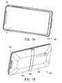
- FIG. 1A and FIG. 1B are schematic diagrams respectively illustrating a handheld electronic device when bodies thereof are in a close state according to an embodiment of the invention.
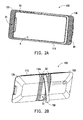
- FIG. 2A and FIG. 2B are schematic diagrams respectively illustrating the handheld electronic device of FIG. 1A when bodies thereof are in a spread state according to an embodiment of the invention.
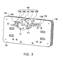
- FIG. 3 and FIG. 4 are exploded views of a part of members in the handheld electronic device of FIG. 1A .
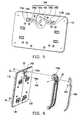
- FIG. 5 is a schematic diagram illustrating a part of the members of FIG. 3 after assembly.
- FIG. 6 is an assembling schematic diagram of a part of members of the handheld electronic device of FIG. 1A viewed from another viewing angle.
- FIG. 7 is a schematic diagram of a part of members of the handheld electronic device of FIG. 6 after assembly.
- FIG. 8A and FIG. 8B are schematic diagrams respectively illustrating situations that a stand of the handheld electronic device of FIG. 6 is closed to and away from a first body.
- FIG. 1A and FIG. 1B are schematic diagrams respectively illustrating a handheld electronic device when bodies thereof are in a close state according to an embodiment of the invention.
- FIG. 2A and FIG. 2B are schematic diagrams respectively illustrating the handheld electronic device of FIG. 1A when bodies thereof are in a spread state according to an embodiment of the invention.
- the close state and the spread state of bodies of the handheld electronic device are clearly presented in different viewing angles.
- the handheld electronic device 100 is, for example, a mobile audio/video device or a smart phone.
- the handheld electronic device 100 includes a first body 110, a second body 120 and a third body 130.
- the second body 120 and the third body 130 are all slidably connected to the first body 110.
- the third body 130 also slides relative to the first body 110 and the second body 120 in an opposite direction, so that the second body 120 and the third body 130 are moved close to or away from each other relative to the first body 110.
- the second body 120 and the third body 130 are switched between the spread state ( FIG. 2A and FIG. 2B ) and the close state ( FIG. 1A and FIG. 1B ) relative to the first body 110.
- FIG. 3 and FIG. 4 are exploded views of a part of members in the handheld electronic device of FIG. 1A .
- a part of the first body 110, the second body 120 and the third body 130 is omitted, and related members of the handheld electronic device 100 are clearly presented in different viewing angles.
- the handheld electronic device 100 further includes a transmission module 140 connected between the first body 110, the second body 120 and the third body 130, and a stand 150 pivoted to the first body 110.
- the second body 120 or the third body 130
- the second body 120 or the third body 130
- the second body 120 and the third body 130 when the second body 120 and the third body 130 are spread relative to the first body 110, the second body 120 and the third body 130 drive the transmission module 140 to move the stand 150, so that the stand 150 is spread from the first body 110, as that shown in FIG. 2B .
- the second body 120 and the third body 130 when the second body 120 and the third body 130 are closed relative to the first body 110, the second body 120 and the third body 130 drive the transmission module 140 to move the stand 150, so that the stand 150 is closed to the first body 110, as that shown in FIG. 2A .
- FIG. 5 is a schematic diagram illustrating a part of the members of FIG. 3 after assembly.
- the second body 120 in order to slidably connect the second body 120 and the third body 130 to the first body 110, the second body 120 has a plurality of guiding slots 122a and 122b, and the third body 130 has a plurality of guiding slots 132a and 132b, while the first body 110 has a plurality of guiding members 112a, 112b, 112c and 112d fastened thereon, wherein the guiding members 112a, 112b, 112c and 112d are respectively coupled to the guiding slots 122a, 122b, 132a and 132b, so that the second body 120 and the third body 130 can slide relative to the first body 110.
- the structure used for slidably connecting the second body 120 and the third body 130 to the first body 110 is not limited to that disclosed by the present embodiment.
- the transmission module 140 in order to drive the transmission module 140 by sliding the second body 120 or the third body 130 relative to the first body 110, the transmission module 140 includes a turntable 142 and two connection rods 144a and 144b.
- the turntable 142 is pivoted to the first body 110.
- the turntable 142 is disposed in a circular hole 111 of the first body 110 based on its circular profile, so as to be pivoted to the first body 110.
- the connection rod 144a has a first end E1 and a second end E2, wherein the first end E1 is pivoted to the turntable 142, and the second end E2 passes through a sliding slot 114a of the first body 110 and is pivoted to the second body 120.
- connection rod 144b is the same to that of the connection rod 144a, and a connection relation of the connection rod 144b is also the same to the connection relation between the connection rod 144a and the turntable 142 and the second body 120, which are not repeated herein.
- the second body 120 when the second body 120 is pushed to slide relative to the first body 110, the second body 120 can drive the second end E2 of the connection rod 144a to slide in the sliding slot 114a, and simultaneously drive the first end E1 of the connection rod 144a to move the turntable 142, so that the turntable 142 is pivotally rotated relative to the first body 110. Meanwhile, the turntable 142 also drives the connection rod 144b, so as to drive the third body 130 to slide relative to the first body 110. Similarly, when the third body 130 is pushed to slide relative to the first body 110, the third body 130 can also simultaneously drive the second body 120 to slide relative to the first body 110 through the transmission module 140.
- the first body 110 has two position-limit slots 116a and 116b respectively connected to the sliding slots 114a and 114b
- the transmission module 140 further includes two position-limit members 146a and 146b, wherein the position-limit member 146a and 146b are movably disposed in the position-limit slots 116a and 116b.
- the position-limit member 146a and the position-limit slot 116a are taken as an example for description.
- the second end E2 of the connection rod 144a passes through the position-limit member 146a and is pivoted to the second body 120.
- FIG. 6 is an assembling schematic diagram of a part of members of the handheld electronic device of FIG. 1A viewed from another viewing angle.
- FIG. 7 is a schematic diagram of a part of members of the handheld electronic device of FIG. 6 after assembly.
- FIG. 8A and FIG. 8B are schematic diagrams respectively illustrating situations that the stand of the handheld electronic device of FIG. 6 is closed to and away from the first body, and in FIG. 8A and FIG. 8B , a back housing 110a, the second body 120 and the third body 130 are omitted to clearly present a motion state of the stand 150. Referring to FIG. 6 , FIG. 8A and FIG.
- the first body 110 includes the back housing 110a, which is fastened to the first body 110, and the stand 150 is pivoted to the back housing 110a so as to be pivoted to the first body 110.
- the turntable 142 has a push portion 142a facing to the stand 150, and the stand 150 has a protrusion 152 facing to the turntable 142.
- the push portion 142a pushes the protrusion 152 to push the stand 150 away from the first body 110, so that the spread stand 150 can serve as a supporting structure of the handheld electronic device 100, as that shown in FIG. 2B and FIG. 8B .
- the transmission module 140 further includes a restoration member 148, for example, a spring.
- the restoration member 148 is connected between the first body 110 and the stand 150.
- the turntable 142 is pivotally rotated relative to the first body 110 so that the push portion 142a does not push the stand 150 away from the first body 110
- the restoration member 148 draws back the stand 150 to the first body 110 from the spread state shown in FIG. 2B through its elastic force, as that shown in FIG. 7 and FIG. 8A .
- the handheld electronic device 100 may have different utilization states.
- orthogonal projections of the second body 120 and the third body 130 on the first body 110 have a profile complied with that of the first body 110, and the second body 120, the third body 130 and the stand 150 also have a consistent profile.
- the stand 150 is accommodated between the second body 120 and the third body 130. In this case, the handheld electronic device 100 has a better portability.
- the first body 110 has a display region A, which is located on a first surface S1 of the first body 110 back to the second body 120 and the third body 130, as that shown in FIG. 2A .
- the second body 120 and the third body 130 respectively have a first speaker region B1 as that shown in FIG. 2A
- the first body 110 has a second speaker region B2, which is located on a second surface S2 of the first body 110 back to the display region A as that shown in FIG. 2B .
- the first speaker regions B1 are shielded by the first body 110, and the second speaker region B2 is shielded by the second body 120 and the third body 130 as that shown in FIG. 1A and FIG. 1B .
- the first speaker regions B1 are substantially exposed outside the first body 110, and are located at two opposite sides of the display region A as that shown in FIG. 2A , and the second speaker region B2 is exposed outside the second body 120 and the third body 130 as that shown in FIG. 2B .
- the first body 110 can be stood on a surface through the stand 150 spread from the first body 110 as that shown in FIG. 2A and FIG. 2B .
- a user can view images displayed by the display region A, and hear sounds sent by the first speaker regions B1 and the second speaker region B2.
- the push portion 142a is substantially a wedge in a curved shape located on a surface of the turntable 142, i.e. a height from a top surface 142b of the push portion 142a to the surface of the turntable 142 is varied along with its curved path.
- a distance that the push portion 142a pushes the protrusion 152 ( FIG. 6 ) away from the first body 110 is varied along with rotation of the turntable 142, so that an angle between the stand 150 and the first body 110 is accordingly varied.
- the stand is pivoted to the first body, and the transmission module is used to drive the stand, so that the stand is opened and closed relative to the first body.
- the handheld electronic device can be stood on the surface, so that a utilization convenience of the handheld electronic device is increased.
Landscapes
- Engineering & Computer Science (AREA)
- Signal Processing (AREA)
- Computer Hardware Design (AREA)
- General Engineering & Computer Science (AREA)
- Theoretical Computer Science (AREA)
- Human Computer Interaction (AREA)
- Physics & Mathematics (AREA)
- General Physics & Mathematics (AREA)
- Telephone Set Structure (AREA)
- Casings For Electric Apparatus (AREA)
Abstract
Description
- The invention relates to a handheld electronic device. Particularly, the invention relates to a handheld electronic device having a stand integrated with a body thereof.
- A handheld electronic device refers to an electronic device capable being held and operated by a user, for example, a mobile phone, a multimedia player, a personal digital assistant (PDA), a handheld computer, a handheld game machine and a handheld satellite navigator, etc. Such type of the electronic device generally has a small size and a light weight to facilitate being carried by the user.
- In order to erect the handheld electronic device on a surface to facilitate the user using the handheld electronic device, i.e. viewing a content displayed on a display screen of the handheld electronic device or hearing a sound sent by the handheld electronic device without holding it, a supporting means, for example, a cradle or a stand is additionally fabricated according to a conventional technique, so that the handheld electronic device can be supported by the supporting means and stood on the surface.
- However, the method of erecting the handheld electronic device through the additional supporting means decreases a utilization convenience of the handheld electronic device.
- The invention is directed to a handheld electronic device having a stand integrated with a body thereof.
- The invention provides a handheld electronic device including a first body, a second body, a stand, and a transmission module. The second body is slidably connected to the first body. The stand is pivoted to the first body. The transmission module is connected between the first body and the second body. When the second body slides relative to the first body, the second body drives the transmission module to move the stand, so that the stand is opened and closed relative to the first body.
- According to the above description, in the invention, the stand is pivoted to the first body, and the transmission module is used to drive the stand, so that the stand is opened and closed relative to the first body. In this way, the handheld electronic device can be stood on the surface, so that a utilization convenience of the handheld electronic device is increased.
- In order to make the aforementioned and other features and advantages of the invention comprehensible, several exemplary embodiments accompanied with figures are described in detail below.
- The accompanying drawings are included to provide a further understanding of the invention, and are incorporated in and constitute a part of this specification. The drawings illustrate embodiments of the invention and, together with the description, serve to explain the principles of the invention.
-
FIG. 1A and FIG. 1B are schematic diagrams respectively illustrating a handheld electronic device when bodies thereof are in a close state according to an embodiment of the invention. -
FIG. 2A and FIG. 2B are schematic diagrams respectively illustrating the handheld electronic device ofFIG. 1A when bodies thereof are in a spread state according to an embodiment of the invention. -
FIG. 3 andFIG. 4 are exploded views of a part of members in the handheld electronic device ofFIG. 1A . -
FIG. 5 is a schematic diagram illustrating a part of the members ofFIG. 3 after assembly. -
FIG. 6 is an assembling schematic diagram of a part of members of the handheld electronic device ofFIG. 1A viewed from another viewing angle. -
FIG. 7 is a schematic diagram of a part of members of the handheld electronic device ofFIG. 6 after assembly. -
FIG. 8A and FIG. 8B are schematic diagrams respectively illustrating situations that a stand of the handheld electronic device ofFIG. 6 is closed to and away from a first body. -
FIG. 1A and FIG. 1B are schematic diagrams respectively illustrating a handheld electronic device when bodies thereof are in a close state according to an embodiment of the invention.FIG. 2A and FIG. 2B are schematic diagrams respectively illustrating the handheld electronic device ofFIG. 1A when bodies thereof are in a spread state according to an embodiment of the invention. Here, the close state and the spread state of bodies of the handheld electronic device are clearly presented in different viewing angles. - Referring to
FIG. 1A to FIG. 2B , in the present embodiment, the handheldelectronic device 100 is, for example, a mobile audio/video device or a smart phone. The handheldelectronic device 100 includes afirst body 110, asecond body 120 and athird body 130. Thesecond body 120 and thethird body 130 are all slidably connected to thefirst body 110. When thesecond body 120 slides relative to thefirst body 110, thethird body 130 also slides relative to thefirst body 110 and thesecond body 120 in an opposite direction, so that thesecond body 120 and thethird body 130 are moved close to or away from each other relative to thefirst body 110. In this way, thesecond body 120 and thethird body 130 are switched between the spread state (FIG. 2A and FIG. 2B ) and the close state (FIG. 1A and FIG. 1B ) relative to thefirst body 110. -
FIG. 3 andFIG. 4 are exploded views of a part of members in the handheld electronic device ofFIG. 1A . Here, a part of thefirst body 110, thesecond body 120 and thethird body 130 is omitted, and related members of the handheldelectronic device 100 are clearly presented in different viewing angles. - Referring to
FIG. 2A, FIG. 2B ,FIG. 3 andFIG. 4 , in the present embodiment, the handheldelectronic device 100 further includes atransmission module 140 connected between thefirst body 110, thesecond body 120 and thethird body 130, and astand 150 pivoted to thefirst body 110. When the second body 120 (or the third body 130) slides relative to thefirst body 110, the second body 120 (or the third body 130) drives thetransmission module 140 to move thestand 150, so that thestand 150 is opened and closed relative to thefirst body 110, as that shown inFIG. 1B andFIG. 2B . - In detail, when the
second body 120 and thethird body 130 are spread relative to thefirst body 110, thesecond body 120 and thethird body 130 drive thetransmission module 140 to move thestand 150, so that thestand 150 is spread from thefirst body 110, as that shown inFIG. 2B . Conversely, when thesecond body 120 and thethird body 130 are closed relative to thefirst body 110, thesecond body 120 and thethird body 130 drive thetransmission module 140 to move thestand 150, so that thestand 150 is closed to thefirst body 110, as that shown inFIG. 2A . -
FIG. 5 is a schematic diagram illustrating a part of the members ofFIG. 3 after assembly. Referring toFIG. 3 to FIG. 5 , in the present embodiment, in order to slidably connect thesecond body 120 and thethird body 130 to thefirst body 110, thesecond body 120 has a plurality of guidingslots third body 130 has a plurality of guidingslots first body 110 has a plurality of guidingmembers members slots second body 120 and thethird body 130 can slide relative to thefirst body 110. However, the structure used for slidably connecting thesecond body 120 and thethird body 130 to thefirst body 110 is not limited to that disclosed by the present embodiment. - Referring to
FIG. 3 to FIG. 5 , in order to drive thetransmission module 140 by sliding thesecond body 120 or thethird body 130 relative to thefirst body 110, thetransmission module 140 includes aturntable 142 and twoconnection rods turntable 142 is pivoted to thefirst body 110. In the present embodiment, theturntable 142 is disposed in acircular hole 111 of thefirst body 110 based on its circular profile, so as to be pivoted to thefirst body 110. Theconnection rod 144a has a first end E1 and a second end E2, wherein the first end E1 is pivoted to theturntable 142, and the second end E2 passes through a sliding slot 114a of thefirst body 110 and is pivoted to thesecond body 120. Similarly, a structure of theconnection rod 144b is the same to that of theconnection rod 144a, and a connection relation of theconnection rod 144b is also the same to the connection relation between theconnection rod 144a and theturntable 142 and thesecond body 120, which are not repeated herein. - In this way, when the
second body 120 is pushed to slide relative to thefirst body 110, thesecond body 120 can drive the second end E2 of theconnection rod 144a to slide in the sliding slot 114a, and simultaneously drive the first end E1 of theconnection rod 144a to move theturntable 142, so that theturntable 142 is pivotally rotated relative to thefirst body 110. Meanwhile, theturntable 142 also drives theconnection rod 144b, so as to drive thethird body 130 to slide relative to thefirst body 110. Similarly, when thethird body 130 is pushed to slide relative to thefirst body 110, thethird body 130 can also simultaneously drive thesecond body 120 to slide relative to thefirst body 110 through thetransmission module 140. - Moreover, in the present embodiment, the
first body 110 has two position-limit slots slots 114a and 114b, and thetransmission module 140 further includes two position-limit members limit member limit slots limit member 146a and the position-limit slot 116a are taken as an example for description. In the present embodiment, the second end E2 of theconnection rod 144a passes through the position-limit member 146a and is pivoted to thesecond body 120. In this way, a fixed sliding path is maintained when the second end E2 of theconnection rod 144a slides in the sliding slot 114a, so as to avoid swaying and unstable sliding when thesecond body 120 slides relative to thefirst body 110. Moreover, regarding the second end E2 of theconnection rod 144b and the slidingslot 114b, the position-limit member 146b and the position-limit slot 116b have the same effect. -
FIG. 6 is an assembling schematic diagram of a part of members of the handheld electronic device ofFIG. 1A viewed from another viewing angle.FIG. 7 is a schematic diagram of a part of members of the handheld electronic device ofFIG. 6 after assembly.FIG. 8A and FIG. 8B are schematic diagrams respectively illustrating situations that the stand of the handheld electronic device ofFIG. 6 is closed to and away from the first body, and inFIG. 8A and FIG. 8B , aback housing 110a, thesecond body 120 and thethird body 130 are omitted to clearly present a motion state of thestand 150. Referring toFIG. 6 ,FIG. 8A and FIG. 8B , in the present embodiment, thefirst body 110 includes theback housing 110a, which is fastened to thefirst body 110, and thestand 150 is pivoted to theback housing 110a so as to be pivoted to thefirst body 110. Theturntable 142 has apush portion 142a facing to thestand 150, and thestand 150 has aprotrusion 152 facing to theturntable 142. When theturntable 142 is pivotally rotated relative to thefirst body 110, thepush portion 142a pushes theprotrusion 152 to push thestand 150 away from thefirst body 110, so that the spread stand 150 can serve as a supporting structure of the handheldelectronic device 100, as that shown inFIG. 2B andFIG. 8B . - Referring to
FIG. 6 andFIG. 7 , thetransmission module 140 further includes arestoration member 148, for example, a spring. Therestoration member 148 is connected between thefirst body 110 and thestand 150. When theturntable 142 is pivotally rotated relative to thefirst body 110 so that thepush portion 142a does not push thestand 150 away from thefirst body 110, therestoration member 148 draws back thestand 150 to thefirst body 110 from the spread state shown inFIG. 2B through its elastic force, as that shown inFIG. 7 andFIG. 8A . - Referring to
FIG. 1A to FIG. 2B , based on motions of thetransmission module 140, the handheldelectronic device 100 may have different utilization states. In detail, when thesecond body 120 and thethird body 130 are in the close state relative to thefirst body 110 as that shown inFIG. 1B , orthogonal projections of thesecond body 120 and thethird body 130 on thefirst body 110 have a profile complied with that of thefirst body 110, and thesecond body 120, thethird body 130 and thestand 150 also have a consistent profile. Now, thestand 150 is accommodated between thesecond body 120 and thethird body 130. In this case, the handheldelectronic device 100 has a better portability. - Moreover, the
first body 110 has a display region A, which is located on a first surface S1 of thefirst body 110 back to thesecond body 120 and thethird body 130, as that shown inFIG. 2A . Thesecond body 120 and thethird body 130 respectively have a first speaker region B1 as that shown inFIG. 2A , and thefirst body 110 has a second speaker region B2, which is located on a second surface S2 of thefirst body 110 back to the display region A as that shown inFIG. 2B . - When the
second body 120 and thethird body 130 are in the close state relative to thefirst body 110, the first speaker regions B1 are shielded by thefirst body 110, and the second speaker region B2 is shielded by thesecond body 120 and thethird body 130 as that shown inFIG. 1A and FIG. 1B . Conversely, when thesecond body 120 and thethird body 130 are in the spread state relative to thefirst body 110, the first speaker regions B1 are substantially exposed outside thefirst body 110, and are located at two opposite sides of the display region A as that shown inFIG. 2A , and the second speaker region B2 is exposed outside thesecond body 120 and thethird body 130 as that shown inFIG. 2B . - When the
second body 120 and thethird body 130 are in the spread state relative to thefirst body 110, and thestand 150 is also in the spread state relative to thefirst body 110, thefirst body 110 can be stood on a surface through thestand 150 spread from thefirst body 110 as that shown inFIG. 2A and FIG. 2B . In this case, a user can view images displayed by the display region A, and hear sounds sent by the first speaker regions B1 and the second speaker region B2. - On the other hand, referring to
FIG. 4 , in the present embodiment, thepush portion 142a is substantially a wedge in a curved shape located on a surface of theturntable 142, i.e. a height from atop surface 142b of thepush portion 142a to the surface of theturntable 142 is varied along with its curved path. In this way, a distance that thepush portion 142a pushes the protrusion 152 (FIG. 6 ) away from thefirst body 110 is varied along with rotation of theturntable 142, so that an angle between thestand 150 and thefirst body 110 is accordingly varied. - In summary, in the invention, the stand is pivoted to the first body, and the transmission module is used to drive the stand, so that the stand is opened and closed relative to the first body. In this way, the handheld electronic device can be stood on the surface, so that a utilization convenience of the handheld electronic device is increased.
- It will be apparent to those skilled in the art that various modifications and variations can be made to the structure of the invention without departing from the scope or spirit of the invention. In view of the foregoing, it is intended that the invention cover modifications and variations of this invention provided they fall within the scope of the following claims and their equivalents.
Claims (12)
- A handheld electronic device, comprising:a first body;a second body, slidably connected to the first body;a stand, pivoted to the first body; anda transmission module, connected between the first body and the second body, wherein when the second body slides relative to the first body, the second body drives the transmission module to move the stand, so that the stand is opened and closed relative to the first body.
- The handheld electronic device as claimed in claim 1, further comprising:a third body, slidably connected to the first body, wherein when the second body slides relative to the first body, the second body drives the transmission module to move the third body sliding relative to the first body and the second body in an opposite direction, so that the second body and the third body are switched between a close state and a spread state relative to the first body.
- The handheld electronic device as claimed in claim 2, wherein when the second body and the third body are in the close state relative to the first body, orthogonal projections of the second body and the third body on the first body have a profile complied with that of the first body.
- The handheld electronic device as claimed in claim 2, wherein when the second body and the third body are in the close state relative to the first body, the stand is closed to the first body, and the second body, the third body and the stand have a consistent profile.
- The handheld electronic device as claimed in claim 2, wherein the first body has a display region located on a first surface of the first body back to the second body and the third body, and the second body and the third body respectively have a first speaker region, when the second body and the third body are in the close state relative to the first body, the first speaker regions are shielded by the first body, and when the second body and the third body are in the spread state relative to the first body, the first speaker regions are substantially exposed outside the first body, and are located at two opposite sides of the display region.
- The handheld electronic device as claimed in claim 2, wherein the first body has a second speaker region located on a second surface of the first body back to the display region, when the second body and the third body are in the close state relative to the first body, the second speaker region is shielded by the second body and the third body, and when the second body and the third body are in the spread state relative to the first body, the second speaker region is exposed outside the second body and the third body.
- The handheld electronic device as claimed in claim 1, wherein the second body has a guiding slot, the first body has a guiding member, and the guiding member is coupled in the guiding slot, so that the second body is capable of sliding relative to the first body.
- The handheld electronic device as claimed in claim 1, wherein the first body has a sliding slot, and the transmission module comprises:a turntable, pivoted to the first body; anda connection rod, having a first end and a second end, the first end being pivoted to the turntable, and the second end passing through the sliding slot and being pivoted to the second body, wherein when the second body slides relative to the first body, the second body drives the second end of the connection rod to slide in the sliding slot, so as to drive the first end of the connection rod to move the turntable, so that the turntable is pivotally rotated relative to the first body.
- The handheld electronic device as claimed in claim 8, wherein the transmission module further comprises:a position-limit member, wherein the first body has a position-limit slot, the position-limit member is movably disposed in the position-limit slot, and the second end of the connection rod passes through the position-limit member and is pivoted to the second body.
- The handheld electronic device as claimed in claim 8, wherein the turntable has a push portion facing to the stand, and the stand has a protrusion facing to the turntable, when the turntable is pivotally rotated relative to the first body, the push portion pushes the protrusion to push the stand away from the first body.
- The handheld electronic device as claimed in claim 10, wherein an angle formed when the push portion pushes the protrusion away from the first body is varied along with rotation of the turntable.
- The handheld electronic device as claimed in claim 10, wherein the transmission module further comprises:a restoration member, connected between the first body and the stand, wherein when the turntable is pivotally rotated relative to the first body so that the push portion does not push the stand away from the first body, the restoration member drives the stand to close to the first body.
Applications Claiming Priority (1)
| Application Number | Priority Date | Filing Date | Title |
|---|---|---|---|
| TW099131622A TWI444033B (en) | 2010-09-17 | 2010-09-17 | Portable electronic device |
Publications (2)
| Publication Number | Publication Date |
|---|---|
| EP2432197A1 true EP2432197A1 (en) | 2012-03-21 |
| EP2432197B1 EP2432197B1 (en) | 2012-11-21 |
Family
ID=44772646
Family Applications (1)
| Application Number | Title | Priority Date | Filing Date |
|---|---|---|---|
| EP11006543A Active EP2432197B1 (en) | 2010-09-17 | 2011-08-09 | Sliding handheld electronic device with pivoting stand |
Country Status (3)
| Country | Link |
|---|---|
| US (1) | US8587933B2 (en) |
| EP (1) | EP2432197B1 (en) |
| TW (1) | TWI444033B (en) |
Cited By (1)
| Publication number | Priority date | Publication date | Assignee | Title |
|---|---|---|---|---|
| EP3712740A1 (en) * | 2019-03-22 | 2020-09-23 | Ganhua Cheng | Protective case for mobile phone and tablet computer |
Families Citing this family (11)
| Publication number | Priority date | Publication date | Assignee | Title |
|---|---|---|---|---|
| US9407984B2 (en) * | 2011-02-24 | 2016-08-02 | Htc Corporation | Method and apparatus for adjusting sound quality |
| US9986073B2 (en) * | 2011-12-23 | 2018-05-29 | Xander Arena | Standoff assistant systems for portable communication devices |
| TWI466623B (en) * | 2012-08-24 | 2014-12-21 | Hon Hai Prec Ind Co Ltd | Electric device |
| USD733693S1 (en) * | 2013-01-16 | 2015-07-07 | Htc Corporation | Portable electronic device |
| USD732498S1 (en) * | 2013-01-16 | 2015-06-23 | Htc Corporation | Portable electronic device |
| JP5643916B1 (en) * | 2014-08-12 | 2014-12-17 | 紀仁 吉田 | Smartphone storage case |
| USD854523S1 (en) * | 2015-10-02 | 2019-07-23 | Samsung Electronics Co., Ltd. | Mobile device |
| USD817297S1 (en) * | 2015-10-07 | 2018-05-08 | Lg Electronics Inc. | Mobile phone |
| JP6684232B2 (en) * | 2017-01-06 | 2020-04-22 | 任天堂株式会社 | Device holding structure |
| USD879080S1 (en) * | 2018-02-23 | 2020-03-24 | Sony Mobile Communications Inc. | Communication device |
| JP6791932B2 (en) * | 2018-11-07 | 2020-11-25 | 任天堂株式会社 | Holding structure of the device |
Citations (5)
| Publication number | Priority date | Publication date | Assignee | Title |
|---|---|---|---|---|
| EP1324571A2 (en) * | 2001-12-28 | 2003-07-02 | Matsushita Electric Industrial Co., Ltd. | Mobile terminal device |
| US20080188273A1 (en) * | 2007-02-07 | 2008-08-07 | Samsung Electronics Co., Ltd. | Apparatus and method for automatic sound control and portable terminal using the same |
| EP2045873A1 (en) * | 2007-09-28 | 2009-04-08 | Samsung Electronics Co., Ltd. | Portable terminal with built-in antenna |
| US20100079938A1 (en) * | 2008-09-26 | 2010-04-01 | Brian Dennis Paschke | Split keyboard with a dual battery pack |
| EP2323352A1 (en) * | 2009-11-11 | 2011-05-18 | HTC Corporation | Handheld electronic device with stand |
Family Cites Families (5)
| Publication number | Priority date | Publication date | Assignee | Title |
|---|---|---|---|---|
| GB2381774B (en) * | 2001-11-06 | 2004-03-03 | Inventec Appliances Corp | Hand-held electronic device with hidden keyboard |
| US7221560B2 (en) * | 2005-01-26 | 2007-05-22 | Cingular Wireless Ii, Llc | Mobile digital device with retractable keyboard |
| TWI280772B (en) | 2005-06-21 | 2007-05-01 | Inventec Appliances Corp | Mobile communication device with prop |
| US7920372B2 (en) * | 2008-09-22 | 2011-04-05 | Nokia Corporation | Electronic handheld device with user interface |
| TWI401015B (en) * | 2010-06-08 | 2013-07-01 | Htc Corp | Handheld device having linkage supporter |
-
2010
- 2010-09-17 TW TW099131622A patent/TWI444033B/en active
-
2011
- 2011-01-26 US US13/014,686 patent/US8587933B2/en active Active
- 2011-08-09 EP EP11006543A patent/EP2432197B1/en active Active
Patent Citations (5)
| Publication number | Priority date | Publication date | Assignee | Title |
|---|---|---|---|---|
| EP1324571A2 (en) * | 2001-12-28 | 2003-07-02 | Matsushita Electric Industrial Co., Ltd. | Mobile terminal device |
| US20080188273A1 (en) * | 2007-02-07 | 2008-08-07 | Samsung Electronics Co., Ltd. | Apparatus and method for automatic sound control and portable terminal using the same |
| EP2045873A1 (en) * | 2007-09-28 | 2009-04-08 | Samsung Electronics Co., Ltd. | Portable terminal with built-in antenna |
| US20100079938A1 (en) * | 2008-09-26 | 2010-04-01 | Brian Dennis Paschke | Split keyboard with a dual battery pack |
| EP2323352A1 (en) * | 2009-11-11 | 2011-05-18 | HTC Corporation | Handheld electronic device with stand |
Cited By (1)
| Publication number | Priority date | Publication date | Assignee | Title |
|---|---|---|---|---|
| EP3712740A1 (en) * | 2019-03-22 | 2020-09-23 | Ganhua Cheng | Protective case for mobile phone and tablet computer |
Also Published As
| Publication number | Publication date |
|---|---|
| US20120069504A1 (en) | 2012-03-22 |
| US8587933B2 (en) | 2013-11-19 |
| EP2432197B1 (en) | 2012-11-21 |
| TWI444033B (en) | 2014-07-01 |
| TW201215075A (en) | 2012-04-01 |
Similar Documents
| Publication | Publication Date | Title |
|---|---|---|
| US8587933B2 (en) | Handheld electronic device | |
| US8494602B2 (en) | Portable electronic device | |
| US8380257B2 (en) | Swing-type mobile communication terminal and swing device thereof | |
| CN101051847B (en) | Portable terminal and sliding type cradle for the same | |
| JP5841456B2 (en) | Cradle device | |
| US20220311843A1 (en) | Electronic device including flexible display | |
| KR20200038903A (en) | Infolding Hinge Structure for Flexible Display Panel | |
| KR101927201B1 (en) | Portable terminal with support plate | |
| US20120168577A1 (en) | Shell for electronic device | |
| US20070210172A1 (en) | Portable cradle | |
| CN111448605A (en) | Folding hinge structure with flexible display panel | |
| TW201042423A (en) | Handheld electronic device | |
| KR20170086999A (en) | Hinge Structure for Mobile Device with Flexible Display installed | |
| US8634196B2 (en) | Locking mechanism and electronic device | |
| CN100448099C (en) | Charging stand for horizontal and vertical positioning of portable devices | |
| US20070184882A1 (en) | Portable communication terminal for games | |
| KR102062240B1 (en) | Hinge appratus for flexible liquid crystal and terminal with the same | |
| EP2341696A1 (en) | Handheld electronic device | |
| KR20210016498A (en) | Folding Hinge Module for Foldable Display Device | |
| US20080047102A1 (en) | Free stop hinge device for portable terminal | |
| CN102138115B (en) | User interface and related devices and methods | |
| CN102413652B (en) | Handheld Electronic Devices | |
| US8538496B2 (en) | Handheld electronic device | |
| CN101902889B (en) | handheld electronic device | |
| KR100842528B1 (en) | Swing type mobile phone and swing device thereof |
Legal Events
| Date | Code | Title | Description |
|---|---|---|---|
| PUAI | Public reference made under article 153(3) epc to a published international application that has entered the european phase |
Free format text: ORIGINAL CODE: 0009012 |
|
| 17P | Request for examination filed |
Effective date: 20110809 |
|
| AK | Designated contracting states |
Kind code of ref document: A1 Designated state(s): AL AT BE BG CH CY CZ DE DK EE ES FI FR GB GR HR HU IE IS IT LI LT LU LV MC MK MT NL NO PL PT RO RS SE SI SK SM TR |
|
| AX | Request for extension of the european patent |
Extension state: BA ME |
|
| GRAP | Despatch of communication of intention to grant a patent |
Free format text: ORIGINAL CODE: EPIDOSNIGR1 |
|
| RIC1 | Information provided on ipc code assigned before grant |
Ipc: H04M 1/04 20060101ALI20120524BHEP Ipc: H04M 1/02 20060101ALI20120524BHEP Ipc: H04M 1/03 20060101AFI20120524BHEP |
|
| GRAS | Grant fee paid |
Free format text: ORIGINAL CODE: EPIDOSNIGR3 |
|
| GRAA | (expected) grant |
Free format text: ORIGINAL CODE: 0009210 |
|
| AK | Designated contracting states |
Kind code of ref document: B1 Designated state(s): AL AT BE BG CH CY CZ DE DK EE ES FI FR GB GR HR HU IE IS IT LI LT LU LV MC MK MT NL NO PL PT RO RS SE SI SK SM TR |
|
| REG | Reference to a national code |
Ref country code: GB Ref legal event code: FG4D |
|
| REG | Reference to a national code |
Ref country code: CH Ref legal event code: EP |
|
| REG | Reference to a national code |
Ref country code: AT Ref legal event code: REF Ref document number: 585566 Country of ref document: AT Kind code of ref document: T Effective date: 20121215 |
|
| REG | Reference to a national code |
Ref country code: IE Ref legal event code: FG4D |
|
| REG | Reference to a national code |
Ref country code: DE Ref legal event code: R096 Ref document number: 602011000455 Country of ref document: DE Effective date: 20130117 |
|
| REG | Reference to a national code |
Ref country code: NL Ref legal event code: T3 |
|
| REG | Reference to a national code |
Ref country code: AT Ref legal event code: MK05 Ref document number: 585566 Country of ref document: AT Kind code of ref document: T Effective date: 20121121 |
|
| REG | Reference to a national code |
Ref country code: LT Ref legal event code: MG4D |
|
| PG25 | Lapsed in a contracting state [announced via postgrant information from national office to epo] |
Ref country code: SE Free format text: LAPSE BECAUSE OF FAILURE TO SUBMIT A TRANSLATION OF THE DESCRIPTION OR TO PAY THE FEE WITHIN THE PRESCRIBED TIME-LIMIT Effective date: 20121121 Ref country code: FI Free format text: LAPSE BECAUSE OF FAILURE TO SUBMIT A TRANSLATION OF THE DESCRIPTION OR TO PAY THE FEE WITHIN THE PRESCRIBED TIME-LIMIT Effective date: 20121121 Ref country code: LT Free format text: LAPSE BECAUSE OF FAILURE TO SUBMIT A TRANSLATION OF THE DESCRIPTION OR TO PAY THE FEE WITHIN THE PRESCRIBED TIME-LIMIT Effective date: 20121121 Ref country code: NO Free format text: LAPSE BECAUSE OF FAILURE TO SUBMIT A TRANSLATION OF THE DESCRIPTION OR TO PAY THE FEE WITHIN THE PRESCRIBED TIME-LIMIT Effective date: 20130221 Ref country code: ES Free format text: LAPSE BECAUSE OF FAILURE TO SUBMIT A TRANSLATION OF THE DESCRIPTION OR TO PAY THE FEE WITHIN THE PRESCRIBED TIME-LIMIT Effective date: 20130304 |
|
| PG25 | Lapsed in a contracting state [announced via postgrant information from national office to epo] |
Ref country code: GR Free format text: LAPSE BECAUSE OF FAILURE TO SUBMIT A TRANSLATION OF THE DESCRIPTION OR TO PAY THE FEE WITHIN THE PRESCRIBED TIME-LIMIT Effective date: 20130222 Ref country code: LV Free format text: LAPSE BECAUSE OF FAILURE TO SUBMIT A TRANSLATION OF THE DESCRIPTION OR TO PAY THE FEE WITHIN THE PRESCRIBED TIME-LIMIT Effective date: 20121121 Ref country code: SI Free format text: LAPSE BECAUSE OF FAILURE TO SUBMIT A TRANSLATION OF THE DESCRIPTION OR TO PAY THE FEE WITHIN THE PRESCRIBED TIME-LIMIT Effective date: 20121121 Ref country code: PT Free format text: LAPSE BECAUSE OF FAILURE TO SUBMIT A TRANSLATION OF THE DESCRIPTION OR TO PAY THE FEE WITHIN THE PRESCRIBED TIME-LIMIT Effective date: 20130321 Ref country code: PL Free format text: LAPSE BECAUSE OF FAILURE TO SUBMIT A TRANSLATION OF THE DESCRIPTION OR TO PAY THE FEE WITHIN THE PRESCRIBED TIME-LIMIT Effective date: 20121121 Ref country code: BE Free format text: LAPSE BECAUSE OF FAILURE TO SUBMIT A TRANSLATION OF THE DESCRIPTION OR TO PAY THE FEE WITHIN THE PRESCRIBED TIME-LIMIT Effective date: 20121121 |
|
| PG25 | Lapsed in a contracting state [announced via postgrant information from national office to epo] |
Ref country code: AT Free format text: LAPSE BECAUSE OF FAILURE TO SUBMIT A TRANSLATION OF THE DESCRIPTION OR TO PAY THE FEE WITHIN THE PRESCRIBED TIME-LIMIT Effective date: 20121121 |
|
| PG25 | Lapsed in a contracting state [announced via postgrant information from national office to epo] |
Ref country code: RS Free format text: LAPSE BECAUSE OF FAILURE TO SUBMIT A TRANSLATION OF THE DESCRIPTION OR TO PAY THE FEE WITHIN THE PRESCRIBED TIME-LIMIT Effective date: 20121121 Ref country code: BG Free format text: LAPSE BECAUSE OF FAILURE TO SUBMIT A TRANSLATION OF THE DESCRIPTION OR TO PAY THE FEE WITHIN THE PRESCRIBED TIME-LIMIT Effective date: 20130221 Ref country code: EE Free format text: LAPSE BECAUSE OF FAILURE TO SUBMIT A TRANSLATION OF THE DESCRIPTION OR TO PAY THE FEE WITHIN THE PRESCRIBED TIME-LIMIT Effective date: 20121121 Ref country code: SK Free format text: LAPSE BECAUSE OF FAILURE TO SUBMIT A TRANSLATION OF THE DESCRIPTION OR TO PAY THE FEE WITHIN THE PRESCRIBED TIME-LIMIT Effective date: 20121121 Ref country code: DK Free format text: LAPSE BECAUSE OF FAILURE TO SUBMIT A TRANSLATION OF THE DESCRIPTION OR TO PAY THE FEE WITHIN THE PRESCRIBED TIME-LIMIT Effective date: 20121121 Ref country code: CZ Free format text: LAPSE BECAUSE OF FAILURE TO SUBMIT A TRANSLATION OF THE DESCRIPTION OR TO PAY THE FEE WITHIN THE PRESCRIBED TIME-LIMIT Effective date: 20121121 |
|
| PG25 | Lapsed in a contracting state [announced via postgrant information from national office to epo] |
Ref country code: IT Free format text: LAPSE BECAUSE OF FAILURE TO SUBMIT A TRANSLATION OF THE DESCRIPTION OR TO PAY THE FEE WITHIN THE PRESCRIBED TIME-LIMIT Effective date: 20121121 Ref country code: RO Free format text: LAPSE BECAUSE OF FAILURE TO SUBMIT A TRANSLATION OF THE DESCRIPTION OR TO PAY THE FEE WITHIN THE PRESCRIBED TIME-LIMIT Effective date: 20121121 |
|
| PLBE | No opposition filed within time limit |
Free format text: ORIGINAL CODE: 0009261 |
|
| STAA | Information on the status of an ep patent application or granted ep patent |
Free format text: STATUS: NO OPPOSITION FILED WITHIN TIME LIMIT |
|
| 26N | No opposition filed |
Effective date: 20130822 |
|
| REG | Reference to a national code |
Ref country code: DE Ref legal event code: R097 Ref document number: 602011000455 Country of ref document: DE Effective date: 20130822 |
|
| PG25 | Lapsed in a contracting state [announced via postgrant information from national office to epo] |
Ref country code: HR Free format text: LAPSE BECAUSE OF FAILURE TO SUBMIT A TRANSLATION OF THE DESCRIPTION OR TO PAY THE FEE WITHIN THE PRESCRIBED TIME-LIMIT Effective date: 20130731 |
|
| PG25 | Lapsed in a contracting state [announced via postgrant information from national office to epo] |
Ref country code: MC Free format text: LAPSE BECAUSE OF FAILURE TO SUBMIT A TRANSLATION OF THE DESCRIPTION OR TO PAY THE FEE WITHIN THE PRESCRIBED TIME-LIMIT Effective date: 20121121 |
|
| REG | Reference to a national code |
Ref country code: IE Ref legal event code: MM4A |
|
| PG25 | Lapsed in a contracting state [announced via postgrant information from national office to epo] |
Ref country code: IE Free format text: LAPSE BECAUSE OF NON-PAYMENT OF DUE FEES Effective date: 20130809 |
|
| REG | Reference to a national code |
Ref country code: CH Ref legal event code: PCOW Free format text: NEW ADDRESS: NO. 23, XINGHUA ROAD TAOYUAN DISTRICT, TAOYUAN CITY 330 (TW) |
|
| REG | Reference to a national code |
Ref country code: CH Ref legal event code: PL |
|
| PG25 | Lapsed in a contracting state [announced via postgrant information from national office to epo] |
Ref country code: LI Free format text: LAPSE BECAUSE OF NON-PAYMENT OF DUE FEES Effective date: 20140831 Ref country code: CH Free format text: LAPSE BECAUSE OF NON-PAYMENT OF DUE FEES Effective date: 20140831 |
|
| PG25 | Lapsed in a contracting state [announced via postgrant information from national office to epo] |
Ref country code: SM Free format text: LAPSE BECAUSE OF FAILURE TO SUBMIT A TRANSLATION OF THE DESCRIPTION OR TO PAY THE FEE WITHIN THE PRESCRIBED TIME-LIMIT Effective date: 20121121 |
|
| PG25 | Lapsed in a contracting state [announced via postgrant information from national office to epo] |
Ref country code: MT Free format text: LAPSE BECAUSE OF FAILURE TO SUBMIT A TRANSLATION OF THE DESCRIPTION OR TO PAY THE FEE WITHIN THE PRESCRIBED TIME-LIMIT Effective date: 20121121 Ref country code: CY Free format text: LAPSE BECAUSE OF FAILURE TO SUBMIT A TRANSLATION OF THE DESCRIPTION OR TO PAY THE FEE WITHIN THE PRESCRIBED TIME-LIMIT Effective date: 20121121 Ref country code: TR Free format text: LAPSE BECAUSE OF FAILURE TO SUBMIT A TRANSLATION OF THE DESCRIPTION OR TO PAY THE FEE WITHIN THE PRESCRIBED TIME-LIMIT Effective date: 20121121 |
|
| PG25 | Lapsed in a contracting state [announced via postgrant information from national office to epo] |
Ref country code: HU Free format text: LAPSE BECAUSE OF FAILURE TO SUBMIT A TRANSLATION OF THE DESCRIPTION OR TO PAY THE FEE WITHIN THE PRESCRIBED TIME-LIMIT; INVALID AB INITIO Effective date: 20110809 Ref country code: MK Free format text: LAPSE BECAUSE OF FAILURE TO SUBMIT A TRANSLATION OF THE DESCRIPTION OR TO PAY THE FEE WITHIN THE PRESCRIBED TIME-LIMIT Effective date: 20121121 Ref country code: LU Free format text: LAPSE BECAUSE OF NON-PAYMENT OF DUE FEES Effective date: 20130809 |
|
| PG25 | Lapsed in a contracting state [announced via postgrant information from national office to epo] |
Ref country code: IS Free format text: LAPSE BECAUSE OF FAILURE TO SUBMIT A TRANSLATION OF THE DESCRIPTION OR TO PAY THE FEE WITHIN THE PRESCRIBED TIME-LIMIT Effective date: 20121121 |
|
| REG | Reference to a national code |
Ref country code: FR Ref legal event code: PLFP Year of fee payment: 6 |
|
| REG | Reference to a national code |
Ref country code: FR Ref legal event code: PLFP Year of fee payment: 7 |
|
| REG | Reference to a national code |
Ref country code: FR Ref legal event code: PLFP Year of fee payment: 8 |
|
| PG25 | Lapsed in a contracting state [announced via postgrant information from national office to epo] |
Ref country code: AL Free format text: LAPSE BECAUSE OF FAILURE TO SUBMIT A TRANSLATION OF THE DESCRIPTION OR TO PAY THE FEE WITHIN THE PRESCRIBED TIME-LIMIT Effective date: 20121121 |
|
| P01 | Opt-out of the competence of the unified patent court (upc) registered |
Effective date: 20230602 |
|
| PGFP | Annual fee paid to national office [announced via postgrant information from national office to epo] |
Ref country code: GB Payment date: 20250619 Year of fee payment: 15 |
|
| PGFP | Annual fee paid to national office [announced via postgrant information from national office to epo] |
Ref country code: NL Payment date: 20250613 Year of fee payment: 15 |
|
| PGFP | Annual fee paid to national office [announced via postgrant information from national office to epo] |
Ref country code: FR Payment date: 20250610 Year of fee payment: 15 |
|
| PGFP | Annual fee paid to national office [announced via postgrant information from national office to epo] |
Ref country code: DE Payment date: 20250618 Year of fee payment: 15 |