EP2432142A1 - Procede, repeteur et systeme de cable sous-marin pour controler le statut de lignes de fibres - Google Patents
Procede, repeteur et systeme de cable sous-marin pour controler le statut de lignes de fibres Download PDFInfo
- Publication number
- EP2432142A1 EP2432142A1 EP10791466A EP10791466A EP2432142A1 EP 2432142 A1 EP2432142 A1 EP 2432142A1 EP 10791466 A EP10791466 A EP 10791466A EP 10791466 A EP10791466 A EP 10791466A EP 2432142 A1 EP2432142 A1 EP 2432142A1
- Authority
- EP
- European Patent Office
- Prior art keywords
- fiber
- probe light
- submarine cable
- coupler
- downlink
- Prior art date
- Legal status (The legal status is an assumption and is not a legal conclusion. Google has not performed a legal analysis and makes no representation as to the accuracy of the status listed.)
- Granted
Links
Images


Classifications
-
- H—ELECTRICITY
- H04—ELECTRIC COMMUNICATION TECHNIQUE
- H04B—TRANSMISSION
- H04B10/00—Transmission systems employing electromagnetic waves other than radio-waves, e.g. infrared, visible or ultraviolet light, or employing corpuscular radiation, e.g. quantum communication
- H04B10/07—Arrangements for monitoring or testing transmission systems; Arrangements for fault measurement of transmission systems
- H04B10/075—Arrangements for monitoring or testing transmission systems; Arrangements for fault measurement of transmission systems using an in-service signal
- H04B10/077—Arrangements for monitoring or testing transmission systems; Arrangements for fault measurement of transmission systems using an in-service signal using a supervisory or additional signal
- H04B10/0773—Network aspects, e.g. central monitoring of transmission parameters
-
- H—ELECTRICITY
- H04—ELECTRIC COMMUNICATION TECHNIQUE
- H04B—TRANSMISSION
- H04B10/00—Transmission systems employing electromagnetic waves other than radio-waves, e.g. infrared, visible or ultraviolet light, or employing corpuscular radiation, e.g. quantum communication
- H04B10/03—Arrangements for fault recovery
- H04B10/032—Arrangements for fault recovery using working and protection systems
Definitions
- the present invention relates to communications technologies, and in particular, to a method for monitoring the state of a fiber line, a repeater, and a submarine cable system.
- a submarine cable service grows rapidly. Due to a special location, a submarine cable is hard to maintain and manage directly. However, the submarine cable is important in a transport network, which requires that an equipment vendor provides a corresponding product for monitoring a submarine equipment. A monitoring device needs to monitor an entire submarine cable system without affecting the submarine fiber service, provide information required by a maintenance engineer, and perform trouble location, monitoring, and management, which helps to maintain the submarine cable system.
- a submarine cable system is constructed by a form of distributing fiber pairs.
- fiber pairs are connected by a form of coupling.
- Probe light undergoes Rayleigh scattering and/or Fresnel reflection in the fiber.
- a part of scattered light and/or reflected light is returned to a probe device through a loopback path.
- the state of the submarine cable line is monitored by analyzing the scattered light and/or reflected light.
- FIG 1 is a simplified block diagram of a submarine cable system.
- the submarine cable line termination A is located on one end (end A) of the submarine cable system
- submarine cable line termination B is located on the other end (end B) of the submarine cable system.
- Termination A and termination B are connected through submarine cables (such as L1, L2, and L3) to transmit the submarine cable service.
- a repeater is used to amplify optical signals transmitted on the fiber in the submarine cable.
- Fiber L11 and fiber L12 are a fiber pair in submarine cable L1. Using terminal A as a reference point, a signal sent from end A to end B is an uplink signal, and a signal received on end A from end B is a downlink signal.
- the fiber that bears the uplink signal is an uplink fiber, such as L11 and L21 in FIG 1 ; and the fiber that bears the downlink signal is a downlink fiber, such as L12 and L22 in FIG 1.
- FIG 1 is only a visualized description of a submarine cable system. In a practical submarine cable system, the distance between end A and end B is generally hundreds or even thousands of kilometers, the number of repeaters between end A and end B is far more than two.
- Monitoring unit A and monitoring device B are configured to monitor fiber lines in the submarine cable. A probe light sent by the monitoring unit A combines with a service light sent by the submarine cable line termination A, and is transmitted to a peer end after passing through the submarine optical cables and the submarine repeater.
- the submarine cable fiber pair is looped back and coupled inside the repeater so that the probe light generated by the monitoring unit A may return to the monitoring unit A through the loopback path in the repeater. In this way, a probe signal is received and analyzed, and the submarine cable system is monitored.
- an out-to-out loopback mode is applied to monitor the state of the submarine line, as shown in FIG 2 .
- the out-to-out loopback mode means that in the repeater, the output end of an optical amplifier (OA) 1 is connected with a coupler 1, and the output end of an OA 2 is connected with a coupler 2; the coupler 1 is connected with the coupler 2 through a fiber, and the path formed by the fiber, the coupler 1, and the coupler 2 is called an out-to-out loopback path.
- OA optical amplifier
- the method for monitoring the submarine cable line is:
- the monitoring device A sends probe light 1, the probe light 1 passes through the OA1 and the coupler 1 in the uplink fiber, and continues to be transmitted in the uplink fiber of the submarine cable between the repeater 1 and the repeater 2; in this uplink fiber, the probe light 1 undergoes Rayleigh scattering and/or Fresnel reflection, and therefore, a part of the probe light 1 is transmitted reversely in the uplink fiber, and this part of light is transmitted to the coupler 1 and coupled to the output end of the OA2 of the downlink fiber along the out-to-out loopback path, and finally, returned to the monitoring device A along the downlink fiber.
- the monitoring device A By detecting the probe light scattered and/or reflected, the monitoring device A analyzes and monitors the state of the uplink fiber and locates the fault of the uplink fiber.
- the method for locating the fault of the downlink fiber is the same as the method for locating the fault of the uplink fiber except that the monitoring device B on the peer end sends probe light 2 and that the scattered and/or reflected probe light of the monitoring device B are transmitted back through the uplink fiber and are finally received and detected.
- a monitoring device on one end of the submarine cable system is capable of monitoring the state of one fiber only (an uplink fiber or a downlink fiber), and is unable to monitor both the state of the uplink fiber and the state of the downlink fiber.
- An embodiment of the present invention provides a method for monitoring a state of a fiber line, including:
- An embodiment of the present invention provides a repeater, including: a first OA, a second OA, a first gating unit, a second gating unit, a first coupler, a second coupler, a third coupler, and a fourth coupler.
- the first OA is configured to amplify optical signals transmitted by an uplink fiber;
- a second OA is configured to amplify optical signals transmitted by a downlink fiber;
- the first gating unit is configured to gate a first probe light, where one end of the first gating unit and an input end of the first OA are both connected with the first coupler, the other end of the first coupler is connected with the uplink fiber of a previous span, the other end of the first gating unit and an input end of the second OA are both connected with the fourth coupler, and the other end of the fourth coupler is connected with the downlink fiber of a next span;
- the second gating unit is configured to gate a second probe light, where one end of the second gating unit and an output end of the first OA are both connected with the second coupler, the other end of the second coupler is connected with the uplink fiber of the next span, the other end of the second gating unit and an output end of the second OA are both connected with the third coupler, and the other end of the third coupler is connected with the downlink fiber of the previous span.
- Another embodiment of the present invention provides a submarine cable system that includes multiple repeaters, in which the multiple repeaters are connected with each other through a submarine cable, where:
- the repeaters gate the first probe light transmitted by the uplink fiber of the previous span and couple this first probe light to the downlink fiber of the next span, and gate the second probe light scattered and/or reflected in the uplink fiber of the next span and couple this second probe light to the downlink fiber of the previous span; and therefore, when receiving the first probe light, the monitoring device may determine that the first probe light is the first probe light scattered and/or reflected in the downlink fiber, and when receiving the second probe light, may determine that the second probe light is the second probe light scattered and/or reflected in the uplink fiber.
- the monitoring device monitors the state of the downlink fiber of the submarine cable according to a received first probe light, and monitors the state of the uplink fiber according to a received second probe light, and therefore, the monitoring device may monitor both the state of the uplink fiber and the state of the downlink fiber of the submarine cable on a single end of the submarine cable system.
- FIG 1 In the submarine cable system shown in FIG 1 , a submarine cable and a repeater are laid underwater, and it is important to monitor the state of a fiber line in the submarine cable.
- An embodiment of the present invention provides a method for monitoring the state of a submarine cable line, and therefore, the monitoring device on either end of the submarine cable system may monitor both the state of an uplink fiber line in the submarine cable and the state of a downlink fiber line in the submarine cable.
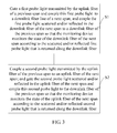
- FIG 3 is a schematic flowchart of this method.
- S1 Gate a first probe light transmitted by an uplink fiber of a previous span and couple this first probe light to a downlink fiber line of a next span; and couple the first probe light scattered and/or reflected in the downlink fiber of the next span to a downlink fiber of the previous span so that the monitoring device monitors the state of the downlink fiber of the next span according to the scattered and/or reflected first probe light that is returned along the downlink fiber.
- the first probe light is sent by the monitoring device on either end of the submarine cable system.
- the monitoring device A on end A sends the first probe light, and the first probe light is coupled by the coupler A into the uplink fiber L11 of the L1 span of the submarine cable.
- the first probe light is transmitted by the uplink fiber L11 to the repeater 1, gated by the repeater 1 and coupled by the repeater 1 to the downlink fiber L22 of the L2 span of the submarine cable, and then transmitted towards the direction of the repeater 2.
- the first probe light undergoes Rayleigh scattering and/or Fresnel reflection.
- a part of the first probe light is returned to the repeater 1, and the repeater 1 amplifies the returned part of the first probe light, and couples the returned part of the first probe light to the downlink fiber L12 of the L1 span of the submarine cable.
- the coupler A separates the first probe light from optical signals in the downlink fiber L12, and sends the first probe light to the monitoring device A.
- the monitoring device A analyzes and monitors the state of the downlink fiber line L22 in the L2 span of the submarine cable according to the first probe light. Specifically, the monitoring device A monitors the state of the downlink fiber L22 (for example, whether the downlink fiber line L22 is cut off) by detecting the optical power of the scattered and/or reflected first probe light.
- the Rayleigh scattering is caused by the defect of a fiber itself or the unevenness of a dopant component, and may occur on each point of the fiber line.
- the Fresnel reflection occurs at the border of two transmission media that have different refractive indexes, for example, occurs at a connector, a mechanical joint, a fiber cut, or a fiber termination.
- S2 Couple a second probe light transmitted by the uplink fiber of the previous span to an uplink fiber of the next span; and gate the second probe light scattered and/or reflected in the uplink fiber of the next span and couple this second probe light to the downlink fiber of the previous span so that the monitoring device monitors the state of the uplink fiber of the next span according to the scattered and/or reflected second probe light that is returned along the downlink fiber.
- the submarine cable system in FIG 1 is still taken as an example to describe this step.
- the monitoring device A on end A sends the second probe light, and the coupler A couples the second probe light to the uplink fiber L11 of the L1 span of the submarine cable.
- the second probe light is transmitted to the repeater 1.
- the repeater 1 amplifies the second probe light and couples it to the uplink fiber L21 of the L2 span of the submarine cable.
- the second probe light undergoes Rayleigh scattering and/or Fresnel reflection. Therefore, a part of the second probe light is returned to the repeater 1.
- the repeater 1 couples the scattered and/or reflected second probe light to the downlink fiber L12 of the L1 span of the submarine cable.
- the scattered and/or reflected second probe light is transmitted back to end A of the submarine cable system along the downlink fiber L12.
- the coupler on end A separates the scattered and/or reflected second probe light from the optical signals transmitted in the downlink fiber of the L1 span, and transmits the second probe light to the monitoring device A.
- the monitoring device A analyzes and monitors the state of the uplink fiber L21 in the L2 span of the submarine cable according to the second probe light.
- the method for monitoring the state of the uplink fiber and the downlink fiber of the L2 span is also applicable to monitoring the state of the uplink fiber and the downlink fiber of other spans.
- FIG 1 shows the submarine cable system in the prior art, in which the repeaters (as illustrated by FIG 2 ) are based on the prior art and are unable to implement the foregoing operations.
- the repeaters of the submarine cable system shown in FIG 1 are cited for the purpose of describing the method for monitoring the state of the submarine cable line according to the present invention.
- step S1 and step S2 may occur simultaneously as long as the monitoring device on either end (such as end A) in the submarine cable system sends the first probe light and the second probe light simultaneously.
- the repeater gates only the first probe light transmitted by the uplink fiber of the previous span and couples only this first probe light to the downlink fiber of the next span, and gates only the second probe light scattered and/or reflected in the uplink fiber of the next span and couples this second probe light to the downlink fiber of the previous span; and therefore, the monitoring device A may determine that a received probe light is scattered and/or reflected in the downlink fiber as long as the received probe light is the first probe light, and may determine that the received probe light is scattered and/or reflected in the uplink fiber as long as the received probe light is the second probe light.
- the monitoring device A may monitor the state of the downlink fiber of the submarine cable according to a received first probe light, and monitor the state of the uplink fiber according to a received second probe light, and therefore, the monitoring device may monitor both the state of the uplink fiber and the state of the downlink fiber of the submarine cable on a single end of the submarine cable system.
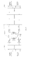
- the repeater includes OA1, OA2, a first gating unit, a second gating unit, a first coupler, a second coupler, a third coupler, and a fourth coupler.
- the first gating unit is configured to gate the first probe light
- the second gating unit is configured to gate the second probe light.
- OA1 is configured to amplify optical signals transmitted in the uplink fiber
- OA2 is configured to amplify optical signals transmitted in the downlink fiber.
- One end (1A) of the first gating unit and an input end of OA1 are connected with one end of the first coupler, the other end of the first coupler is connected with the uplink fiber (such as L11) of the previous span, the other end (1B) of the first gating unit and the input end of OA2 are connected with the fourth coupler, and the other end of the fourth coupler is connected with the downlink fiber (such as L22) of the next span.
- a path formed by "the first coupler - the first gating unit - the third coupler" is called an in-to-in loopback path.
- One end (2A) of the second gating unit and an output end of OA1 are connected with one end of the second coupler, the other end of the second coupler is connected with the uplink fiber (such as L21) of the next span, the other end (2B) of the second gating unit and the output end of OA2 are connected with the third coupler, and the other end of the third coupler is connected with the downlink fiber (such as L12) of the previous span.
- a path formed by "the second coupler - the second gating unit - the third coupler" is called an out-to-out loopback path.
- a monitoring device may monitor both the state of the uplink fiber and the state of the downlink fiber of the submarine cable on a single end of the submarine cable system.
- the following describes a working process of a repeater at the time of monitoring the state of the uplink fiber and the state of the downlink fiber.
- the monitoring device (such as monitoring device A on end A shown in FIG 1 ) on a end of the submarine cable system sends a first probe light to monitor the state of the downlink fiber of the submarine cable.
- the first probe light and a service light that is transmitted by submarine cable line termination A are coupled by the coupler A to the uplink fiber.
- the first probe light and the service light may also be coupled by a multiplexer-demultiplexer to the uplink fiber.
- the service light is optical signals that bear a service, and the wavelength of the service light is different from that of the first probe light.
- the service light and the first probe light are transmitted by the uplink fiber (such as uplink fiber L11) to the repeater shown in FIG 4 .
- the processing of the service light in the repeater is similar to the processing of the first probe light in the repeater. Therefore, the processing of the first probe light in the repeater is detailed below.
- the first coupler divides the first probe light transmitted by the uplink fiber L11 into two parts. One part is amplified by OA1 and coupled by the second coupler to the uplink fiber L21 in the next span L2 of the submarine cable; and the other part is coupled through the in-to-in loopback path that includes the first gating unit to the downlink fiber L22 in the next span L2 of the submarine cable, and the transmission direction of this part of the first probe light in the downlink fiber L22 is opposite to the transmission direction of a service light in the downlink fiber L22.
- the first probe light transmitted in the downlink fiber L22 undergoes Rayleigh scattering and/or Fresnel reflection in the downlink fiber L22, and therefore, a part of the first probe light is returned to the repeater shown in FIG 4 , and the fourth coupler in the repeater divides a scattered and/or reflected part of the first probe light into two parts.
- One part is amplified by OA2 and then coupled by the third coupler to the downlink fiber L12 in the previous span L1 of the submarine cable, and finally returned to the monitoring device A on end A; and the other part is coupled through the in-to-in loopback path to the uplink fiber L11 in the previous span L1 of the submarine cable, and transmitted to a previous repeater along a direction opposite to the transmission direction of the service light in the uplink fiber L11. In the previous repeater, the reversely transmitted scattered and/or reflected part of the first probe light is blocked.
- the first probe light transmitted in the uplink fiber L21 also undergoes Rayleigh scattering and/or Fresnel reflection, and therefore, a part of the first probe light is returned to the repeater shown in FIG 4 , and the second coupler divides the scattered and/or reflected portion of the first probe light into two parts.
- One part is blocked by the second gating unit in the out-to-out loopback path because the second gating unit selects only the second probe light; and the other part is blocked by OA1 because an optical isolator is integrated in every OA to isolate transmission of a reverse light. Therefore, the part of the first probe light, which is scattered and/or reflected in the uplink fiber L21, is not able to return to the monitoring device A on end A.
- the monitoring device A on end A may determine the first probe light as the first probe light scattered and/or reflected in the downlink fiber when receiving the first probe light transmitted back along the downlink fiber, and may analyze the first probe light to know the state of the downlink fiber.
- the monitoring device A on end A sends the second probe light.
- the second probe light is transmitted by the uplink fiber L11 to the repeater shown in FIG 4 .
- the first coupler in the repeater divides the second probe light into two parts. One part is amplified by OA1 and coupled by the second coupler to the uplink fiber L21 in the next span L2 of the submarine cable; and the other part is blocked by the first gating unit when passing through the in-to-in loopback path because the first gating unit selects only the first probe light rather than the second probe light.
- the second probe light transmitted in the uplink fiber L21 undergoes Rayleigh scattering and/or Fresnel reflection in the uplink fiber, and therefore, a part of the second probe light is returned to the repeater shown in FIG 4 , and the second coupler divides the scattered and/or reflected part of the second probe light into two parts. One part is coupled through the out-to-out loopback path to the downlink fiber in the previous span L1 of the submarine cable, and finally returned to the monitoring device A on end A; and the other part is blocked by OA1.
- the second probe light finally transmitted back to end A along the downlink fiber is the second probe light scattered and/or reflected in the uplink fiber L21; and the monitoring device A may determine the second probe light as the second probe light scattered and/or reflected in the uplink fiber when receiving the second probe light transmitted back along the downlink fiber, and may analyze the second probe light to know the state of the uplink fiber.
- wavelength of the first probe light is different from that of the second probe light, and wavelength of the first probe light and wavelength of the second probe light are also different from wavelength of the service light.
- the first gating unit and the second gating unit in this embodiment may be filters.
- the first gating unit is a band-pass filter
- the second gating unit is a band-stop filter.
- a passband range of the band-pass filter may coincide with a stopband range of the band-stop filter, and frequency of the first probe light falls within the passband range of the band-pass filter, but frequency of the second probe light falls outside the stopband range of the band-stop filter.
- the frequency of the first probe light is 193.435 THz
- the frequency of the second probe light is 193.485 THz
- the stopband range of the band-stop filter may be set to 193.425 THz - 193.475 THz
- the passband range of the band-pass filter may be set to 193.425 THz - 193.475 THz.
- the passband range of the band-pass filter does not coincide with the stopband range of the band-stop filter completely, or even does not coincide with the stopband range of the band-stop filter at all.
- the passband range of the band-pass filter is set to 193.430 THz - 193.480 THz
- the stopband range of the band-stop filter is set to 193.415 THz - 193.465 THz.
- This embodiment does not restrict which filter is used as the first gating unit or the second gating unit.
- the filters meet the requirements if the filter serving as the first gating unit lets pass the first probe light and blocks the second probe light, while the filter serving as the second gating unit lets pass of the second probe light and blocks the first probe light. Therefore, the following combinations are also appropriate: (1) The first gating unit is a band-stop filter, and the second gating unit is a band-pass filter; or (2) the first gating unit is a band-pass filter, and the second gating unit is a band-pass filter; or (3) the first gating unit is a band-stop filter, and the second gating unit is a band-stop filter.
- the monitoring device on either end of the submarine cable system may monitor both the state of the uplink fiber and the state of the downlink fiber of the submarine cable. If the repeaters in the submarine cable system shown in FIG 1 apply the structure described in this embodiment, the monitoring device A on end A sends the first probe light, and analyzes and monitors the state of the downlink fiber in the submarine cable according to the received first probe light that is transmitted back from the downlink fiber. The monitoring device A also sends the second probe light, and analyzes and monitors the state of the uplink fiber in the submarine cable according to the received second probe light that is transmitted back from the downlink fiber. Therefore, the monitoring device may monitor both the state of the uplink fiber and the state of the downlink fiber of the submarine cable on a single end of the submarine cable system.
- FIG 5 Another embodiment of the present invention provides a submarine cable system, and a structure of the submarine cable system is as shown in FIG 5 , in which the submarine cable system includes at least one repeater (such as repeater 1) of a structure shown in FIG 4 .
- the submarine cable system also includes submarine cable line termination A, monitoring device A, and coupler A, which are located on end A; and submarine cable line termination B, monitoring device B, and coupler B, which are located on end B.
- Multiplexer-demultiplexers may replace the coupler A and the coupler B in the submarine cable system in this embodiment.
- the following describes how to monitor the state of the uplink fiber and the state of the downlink fiber on a single end of the submarine cable system shown in FIG 5 .
- the monitoring on end A is still taken as an example. It is understandable that monitoring on end B is similar to the monitoring on end A.
- the monitoring device A on end A sends a first probe light, and monitors the state of the downlink fiber according to the received first probe light that is transmitted back from the downlink fiber.
- the monitoring device A further sends a second probe light, and monitors the state of the uplink fiber in the submarine cable according to the received second probe light that is transmitted back from the downlink fiber.
- the following example describes how to monitor the state of the downlink fiber according to the received first probe light that is transmitted back from the downlink fiber.
- the monitoring device A also samples the first probe light returned along the downlink fiber to obtain power information of this first probe light.
- the monitoring device obtains a curve of power of the first probe light returned by the downlink fiber to the monitoring device A, where the power changes with a fiber distance.
- Figure 6 shows the curve.
- a fiber that extends dozens of kilometers is generally spliced from multiple shorter fibers through connectors, splice joints, and mechanical joints.
- the connectors, splice joints, and mechanical joints are called discontinuous points.
- the curve in FIG 6 shows that the power of the first probe light returned from the discontinuous points changes transiently relative to the first probe light returned from the fiber before and after the discontinuous points. That is because the first probe light undergoes Rayleigh scattering in the fiber between the discontinuous points, and undergoes Fresnel reflection at the discontinuous points. In the Rayleigh scattering, scattering strength is very small, only a very small part of the first probe light is scattered back to the monitoring device A on end A.
- the monitoring device may determine locations of the discontinuous points in each span of the fiber accurately. Especially, when a span of a fiber is cut (a fiber cut is a type of terminations shown in FIG 6 ), the fiber cut may be located accurately by the foregoing method, and the purpose of monitoring a fiber state is fulfilled.
- the method for monitoring the state of the uplink fiber according to the second probe light transmitted back from the downlink fiber is almost the same as the method for monitoring the state of the downlink fiber according to the first probe light transmitted back from the downlink fiber, and is not repeated here any further.
- the method for monitoring the state of the downlink fiber or the state of the uplink fiber according to the first probe light or the second probe light transmitted back from the downlink fiber is applicable to other embodiments of the present invention.
- the monitoring device A on end A and the monitoring device B on end B may be an Optical Time Domain Reflector (OTDR).
- OTDR Optical Time Domain Reflector
- the monitoring device may monitor both the uplink fiber and the downlink fiber in the L1 span on end A of the submarine cable system, and may monitor, on end B of the submarine cable system, states of both the uplink fiber and the downlink fiber of the submarine cable between end A and the repeater.
- more or all repeaters in the submarine cable system apply the repeater of the structure shown in FIG 4 , and the monitoring device may monitor, on either end of the submarine cable system, both the uplink fiber and the downlink fiber in more or all spans of the submarine cable.
- the submarine cable system in this embodiment reduces a requirement on a dynamic range of the monitoring device (the dynamic range decides the maximum length of a single span of the fiber that may be detected by a detection device).
- the L1 span of the submarine cable in FIG 5 is 120 km, and the loss of a fiber in the submarine cable is 0.2 dB/km. That is, the monitoring device in a landing station requires a dynamic range of at least 24 dB if the repeaters shown in FIG 2 are applied.
- the monitoring device A and the monitoring device B require a dynamic range of only 12 dB, and the monitoring device A monitors the state of the 60 km fiber on the left end of the L1 span of the submarine cable, and the monitoring device B monitors the state of the 60 km fiber on the right end of the L1 span of the submarine cable.
- the monitoring device A and the monitoring device B each report a monitoring result to a network management system.
- the network management system combines the monitoring result of the monitoring device A with the monitoring result of the monitoring device B to obtain the state of the entire length of the fiber in the L1 span of the submarine cable.
- the monitoring device is unable to monitor the state of the entire length of the fiber in the L1 span of the submarine cable on the condition that the dynamic range of the monitoring device is reduced. Because the requirement on the dynamic range of the monitoring device is lowered, the system cost is reduced.
- both the uplink fiber and the downlink fiber are defined by using end A of the submarine cable system as a reference point in order to unify the expression. It is understandable that, in practice, end B of the submarine cable system may be used as a reference point.
- an originally defined uplink fiber changes to be the downlink fiber
- an originally defined downlink fiber changes to be the uplink fiber.
- the storage media may be a magnetic disk, CD-ROM, Read-Only Memory (ROM), or Random Access Memory (RAM).
Landscapes
- Physics & Mathematics (AREA)
- Electromagnetism (AREA)
- Engineering & Computer Science (AREA)
- Computer Networks & Wireless Communication (AREA)
- Signal Processing (AREA)
- Optical Communication System (AREA)
Applications Claiming Priority (2)
| Application Number | Priority Date | Filing Date | Title |
|---|---|---|---|
| CN2009101082898A CN101931471B (zh) | 2009-06-23 | 2009-06-23 | 一种监控光纤线路状态的方法、中继器和海缆系统 |
| PCT/CN2010/073784 WO2010148960A1 (fr) | 2009-06-23 | 2010-06-11 | Procede, repeteur et systeme de cable sous-marin pour controler le statut de lignes de fibres |
Publications (3)
| Publication Number | Publication Date |
|---|---|
| EP2432142A1 true EP2432142A1 (fr) | 2012-03-21 |
| EP2432142A4 EP2432142A4 (fr) | 2012-12-19 |
| EP2432142B1 EP2432142B1 (fr) | 2018-01-17 |
Family
ID=43370419
Family Applications (1)
| Application Number | Title | Priority Date | Filing Date |
|---|---|---|---|
| EP10791466.5A Not-in-force EP2432142B1 (fr) | 2009-06-23 | 2010-06-11 | Procede, repeteur et systeme de cable sous-marin pour controler le statut de lignes de fibres |
Country Status (4)
| Country | Link |
|---|---|
| US (1) | US8676053B2 (fr) |
| EP (1) | EP2432142B1 (fr) |
| CN (1) | CN101931471B (fr) |
| WO (1) | WO2010148960A1 (fr) |
Families Citing this family (14)
| Publication number | Priority date | Publication date | Assignee | Title |
|---|---|---|---|---|
| CN101931471B (zh) * | 2009-06-23 | 2013-08-07 | 华为海洋网络有限公司 | 一种监控光纤线路状态的方法、中继器和海缆系统 |
| CN102801464B (zh) * | 2011-05-27 | 2015-03-25 | 华为海洋网络有限公司 | 检测海底光缆线路的方法、传送装置和系统 |
| DE202012004728U1 (de) * | 2012-05-10 | 2013-08-13 | Mic Ag | Datenkommunikationsvorrichtung |
| CN103416008B (zh) * | 2012-05-21 | 2016-08-10 | 华为海洋网络有限公司 | 中继器及环回模式切换方法 |
| US9276694B2 (en) * | 2012-10-08 | 2016-03-01 | Tyco Electronics Subsea Communications Llc | Fault recovery in branched optical networks |
| JP6699721B2 (ja) * | 2016-03-30 | 2020-05-27 | 日本電気株式会社 | 信号折返し回路及び信号折返し方法 |
| US9755734B1 (en) * | 2016-06-09 | 2017-09-05 | Google Inc. | Subsea optical communication network |
| EP3588809A4 (fr) * | 2017-02-22 | 2020-02-26 | Nec Corporation | Système de relais optique |
| WO2018210470A1 (fr) | 2017-05-17 | 2018-11-22 | Alcatel Lucent | Utilisation de filtres passe-bande dans des trajets de signaux de supervision d'un système de transport optique |
| EP3599726B1 (fr) | 2018-07-25 | 2021-05-19 | Alcatel Submarine Networks | Équipement de surveillance pour un système de transport optique |
| EP3696997B1 (fr) | 2019-02-15 | 2022-06-15 | Alcatel Submarine Networks | Circuit optique de surveillance symétrique pour un répétiteur optique bidirectionnel |
| WO2021049099A1 (fr) * | 2019-09-10 | 2021-03-18 | 日本電気株式会社 | Système de communication optique sous-marin, procédé de transport de résultats de surveillance et support non transitoire lisible par ordinateur dans lequel est stocké un programme |
| CN113381804B (zh) * | 2020-03-10 | 2022-12-27 | 华为技术有限公司 | 一种同缆概率检测的方法以及装置 |
| CN111953410B (zh) * | 2020-08-20 | 2022-03-04 | 中电科思仪科技股份有限公司 | 一种用于相干光时域反射计海底光缆模拟测试装置及方法 |
Citations (6)
| Publication number | Priority date | Publication date | Assignee | Title |
|---|---|---|---|---|
| GB2294374A (en) * | 1992-06-10 | 1996-04-24 | Kokusai Denshin Denwa Co Ltd | A supervising loopback circuit and a transmitting and receiving circuit for an optical repeater system |
| US5926263A (en) * | 1996-10-10 | 1999-07-20 | Tyco Submarine Systems Ltd. | Side-tone OTDR for in-service optical cable monitoring |
| EP0981215A2 (fr) * | 1998-08-14 | 2000-02-23 | Nec Corporation | Répéteur optique à amplificateur |
| US6301404B1 (en) * | 1998-03-17 | 2001-10-09 | Nec Corporation | Supervisory signal optical bypass circuit, optical amplifying repeater and supervisory system |
| EP1241805A2 (fr) * | 2001-03-16 | 2002-09-18 | Fujitsu Limited | Localisation de défaut dans un système de transmission optique |
| US20050002386A1 (en) * | 2003-06-18 | 2005-01-06 | Nec Corporation | Signal repeater and switching device, method of detecting connecting relation between signal repeater and switching device and communication system |
Family Cites Families (21)
| Publication number | Priority date | Publication date | Assignee | Title |
|---|---|---|---|---|
| JPH0918411A (ja) * | 1995-06-27 | 1997-01-17 | Fujitsu Ltd | 光中継器 |
| GB9526185D0 (en) * | 1995-12-21 | 1996-02-21 | Stc Submarine Systems Ltd | Fiber-break detection in bi-directional optical amplifier systems |
| US6452701B1 (en) * | 1997-03-19 | 2002-09-17 | Fujitsu Limited | Wavelength division multiplexing communications network supervisory system |
| JP3439323B2 (ja) * | 1997-06-18 | 2003-08-25 | 安藤電気株式会社 | 多段多分岐光線路の試験装置 |
| US6317535B1 (en) * | 1999-08-24 | 2001-11-13 | Lucent Technologies Inc. | System and method for testing optical fibers that lead between a telecommunications provider and a customer's premises |
| CN1127234C (zh) | 1999-12-02 | 2003-11-05 | 深圳市中兴通讯股份有限公司 | 波分复用光传输系统中光监控通道装置、系统及实现方法 |
| US6868233B2 (en) * | 2000-12-14 | 2005-03-15 | Alcatel Usa Sourcing, L.P. | Wavelength agile optical transponder for bi-directional, single fiber WDM system testing |
| CN100486148C (zh) | 2001-07-02 | 2009-05-06 | 中兴通讯股份有限公司 | 光监控通道环回保护的装置 |
| JP4632585B2 (ja) * | 2001-07-16 | 2011-02-16 | 富士通株式会社 | 光伝送システム |
| US20040047629A1 (en) * | 2002-08-20 | 2004-03-11 | Red Sky Systems, Inc. | Adaptor arrangement for detecting faults in an optically amplified multi-span transmission system using a remotely located OTDR |
| EP1443685B1 (fr) | 2003-02-01 | 2006-05-24 | Agilent Technologies, Inc., a corporation of the State of Delaware | Méthode et appareil de surveillance de performance des canaux dans des systèmes optiques de multiplexage par répartition en longueur d'onde dense |
| US7388657B2 (en) * | 2005-08-22 | 2008-06-17 | Tyco Telecommunications (Us) Inc. | System and method for monitoring an optical communication system |
| CN201025711Y (zh) * | 2006-09-21 | 2008-02-20 | 黄中海 | 一种光缆故障自检的波分传输系统 |
| US8135274B2 (en) * | 2008-02-11 | 2012-03-13 | Tyco Electronics Subsea Communications Llc | System and method for fault identification in optical communication systems |
| JP5136240B2 (ja) * | 2008-06-26 | 2013-02-06 | 日本電気株式会社 | 伝送路監視システム |
| US8009983B2 (en) * | 2008-06-26 | 2011-08-30 | Tyco Electronics Subsea Communications Llc | High loss loop back for long repeater span |
| WO2010132656A1 (fr) * | 2009-05-14 | 2010-11-18 | Tyco Electronics Subsea Communications Llc | Configuration de dérivation comprenant un module de dérivation séparé ainsi qu'un module de filtrage de longueur d'onde prédéterminée, et système et procédé correspondants |
| CN101931471B (zh) * | 2009-06-23 | 2013-08-07 | 华为海洋网络有限公司 | 一种监控光纤线路状态的方法、中继器和海缆系统 |
| CN101964924B (zh) * | 2009-07-24 | 2013-11-06 | 华为技术有限公司 | 无源光网络中传输信息的方法、装置和系统 |
| CN101998181B (zh) * | 2009-08-10 | 2013-09-11 | 中兴通讯股份有限公司 | Sncp业务迁移方法及装置 |
| US8483559B2 (en) * | 2011-01-07 | 2013-07-09 | Tyco Electronics Subsea Communications Llc | System and method for monitoring a branched optical communication system |
-
2009
- 2009-06-23 CN CN2009101082898A patent/CN101931471B/zh active Active
-
2010
- 2010-06-11 WO PCT/CN2010/073784 patent/WO2010148960A1/fr active Application Filing
- 2010-06-11 EP EP10791466.5A patent/EP2432142B1/fr not_active Not-in-force
-
2011
- 2011-12-19 US US13/330,097 patent/US8676053B2/en active Active
Patent Citations (6)
| Publication number | Priority date | Publication date | Assignee | Title |
|---|---|---|---|---|
| GB2294374A (en) * | 1992-06-10 | 1996-04-24 | Kokusai Denshin Denwa Co Ltd | A supervising loopback circuit and a transmitting and receiving circuit for an optical repeater system |
| US5926263A (en) * | 1996-10-10 | 1999-07-20 | Tyco Submarine Systems Ltd. | Side-tone OTDR for in-service optical cable monitoring |
| US6301404B1 (en) * | 1998-03-17 | 2001-10-09 | Nec Corporation | Supervisory signal optical bypass circuit, optical amplifying repeater and supervisory system |
| EP0981215A2 (fr) * | 1998-08-14 | 2000-02-23 | Nec Corporation | Répéteur optique à amplificateur |
| EP1241805A2 (fr) * | 2001-03-16 | 2002-09-18 | Fujitsu Limited | Localisation de défaut dans un système de transmission optique |
| US20050002386A1 (en) * | 2003-06-18 | 2005-01-06 | Nec Corporation | Signal repeater and switching device, method of detecting connecting relation between signal repeater and switching device and communication system |
Non-Patent Citations (1)
| Title |
|---|
| See also references of WO2010148960A1 * |
Also Published As
| Publication number | Publication date |
|---|---|
| US20120106947A1 (en) | 2012-05-03 |
| US8676053B2 (en) | 2014-03-18 |
| CN101931471A (zh) | 2010-12-29 |
| WO2010148960A1 (fr) | 2010-12-29 |
| EP2432142B1 (fr) | 2018-01-17 |
| EP2432142A4 (fr) | 2012-12-19 |
| CN101931471B (zh) | 2013-08-07 |
Similar Documents
| Publication | Publication Date | Title |
|---|---|---|
| EP2432142B1 (fr) | Procede, repeteur et systeme de cable sous-marin pour controler le statut de lignes de fibres | |
| US7310134B2 (en) | Device and method of optical fiber condition monitoring in optical networks | |
| US8175454B2 (en) | Fault locator for long haul transmission system | |
| US9276672B2 (en) | Method, transport apparatus, and system for detecting submarine optical cable line | |
| CN107332101B (zh) | 一种可动态执行光时域反射检测的组件和检测方法 | |
| EP1023587B1 (fr) | Reflectometre optique dans le domaine temporel (otdr) a effet local destine a la surveillance de cables optiques en service | |
| US6842586B2 (en) | OTDR arrangement for detecting faults in an optical transmission system employing two pairs of unidirectional optical fibers | |
| EP0868793B1 (fr) | Detection de la rupture de fibres dans des reseaux de transmission de signaux optiques | |
| EP1796295A1 (fr) | Procédé destiné à la détection et à la localisation de perturbations sur un trajet de transmission optique et un système de transmission optique | |
| US7099581B2 (en) | OTDR arrangement for detecting faults in an optical transmission system on a span by span basis | |
| EP1095472B1 (fr) | Procede et dispositif pour effectuer des mesures de controle et de surveillance sur des lignes de transmission optique | |
| JP6196124B2 (ja) | 光ファイバ伝送路モニタシステム | |
| CN110945800B (zh) | 一种光性能监测装置及方法 | |
| US9112617B2 (en) | Method and device for monitoring a detachable fiber-optic connection, especially in a fiber-optic transmission device or system | |
| US10128942B2 (en) | Method of transmitting an optical data signal via a fiber optical medium in opposite directions at the same carrier wavelength | |
| KR20170042290A (ko) | 분산형 라만 증폭기 시스템 | |
| CN106100746B (zh) | 一种用于otdr光纤检测的测试波中继设备及其控制方法 | |
| EP3528401A1 (fr) | Mesure otdr unique pour une pluralité de fibres | |
| JPH04351935A (ja) | 光線路試験監視システム | |
| Bréda | Monitoring Optical Data Connection between Protected Rooms in Smart Cities | |
| US20240027259A1 (en) | Multi-span optical fiber das system with amplified-filtered loopback (aflb) | |
| US20240297711A1 (en) | System and Method of Optical Fiber Characterization Via Communication Over Multiple Intelligent Panels | |
| JPS63160436A (ja) | 光信号線路の保守方法 | |
| Ab-Rahman et al. | Graphical User Interface Capabilities of MATLAB in Centralized Failure Detection System (CFDS) | |
| Takaya et al. | Technique for finding and identifying filters that cut off OTDR lights in front of ONU from a central office |
Legal Events
| Date | Code | Title | Description |
|---|---|---|---|
| PUAI | Public reference made under article 153(3) epc to a published international application that has entered the european phase |
Free format text: ORIGINAL CODE: 0009012 |
|
| 17P | Request for examination filed |
Effective date: 20111208 |
|
| AK | Designated contracting states |
Kind code of ref document: A1 Designated state(s): AL AT BE BG CH CY CZ DE DK EE ES FI FR GB GR HR HU IE IS IT LI LT LU LV MC MK MT NL NO PL PT RO SE SI SK SM TR |
|
| DAX | Request for extension of the european patent (deleted) | ||
| A4 | Supplementary search report drawn up and despatched |
Effective date: 20121115 |
|
| RIC1 | Information provided on ipc code assigned before grant |
Ipc: H04B 10/08 20060101AFI20121109BHEP |
|
| REG | Reference to a national code |
Ref country code: DE Ref legal event code: R079 Ref document number: 602010048143 Country of ref document: DE Free format text: PREVIOUS MAIN CLASS: H04B0010080000 Ipc: H04B0010032000 |
|
| GRAP | Despatch of communication of intention to grant a patent |
Free format text: ORIGINAL CODE: EPIDOSNIGR1 |
|
| STAA | Information on the status of an ep patent application or granted ep patent |
Free format text: STATUS: GRANT OF PATENT IS INTENDED |
|
| RIC1 | Information provided on ipc code assigned before grant |
Ipc: H04B 10/077 20130101ALI20170404BHEP Ipc: H04B 10/032 20130101AFI20170404BHEP |
|
| INTG | Intention to grant announced |
Effective date: 20170428 |
|
| GRAS | Grant fee paid |
Free format text: ORIGINAL CODE: EPIDOSNIGR3 |
|
| GRAJ | Information related to disapproval of communication of intention to grant by the applicant or resumption of examination proceedings by the epo deleted |
Free format text: ORIGINAL CODE: EPIDOSDIGR1 |
|
| GRAL | Information related to payment of fee for publishing/printing deleted |
Free format text: ORIGINAL CODE: EPIDOSDIGR3 |
|
| STAA | Information on the status of an ep patent application or granted ep patent |
Free format text: STATUS: REQUEST FOR EXAMINATION WAS MADE |
|
| GRAP | Despatch of communication of intention to grant a patent |
Free format text: ORIGINAL CODE: EPIDOSNIGR1 |
|
| STAA | Information on the status of an ep patent application or granted ep patent |
Free format text: STATUS: GRANT OF PATENT IS INTENDED |
|
| INTC | Intention to grant announced (deleted) | ||
| INTG | Intention to grant announced |
Effective date: 20171012 |
|
| GRAA | (expected) grant |
Free format text: ORIGINAL CODE: 0009210 |
|
| STAA | Information on the status of an ep patent application or granted ep patent |
Free format text: STATUS: THE PATENT HAS BEEN GRANTED |
|
| AK | Designated contracting states |
Kind code of ref document: B1 Designated state(s): AL AT BE BG CH CY CZ DE DK EE ES FI FR GB GR HR HU IE IS IT LI LT LU LV MC MK MT NL NO PL PT RO SE SI SK SM TR |
|
| REG | Reference to a national code |
Ref country code: GB Ref legal event code: FG4D |
|
| REG | Reference to a national code |
Ref country code: CH Ref legal event code: EP |
|
| REG | Reference to a national code |
Ref country code: IE Ref legal event code: FG4D |
|
| REG | Reference to a national code |
Ref country code: AT Ref legal event code: REF Ref document number: 965068 Country of ref document: AT Kind code of ref document: T Effective date: 20180215 |
|
| REG | Reference to a national code |
Ref country code: DE Ref legal event code: R096 Ref document number: 602010048143 Country of ref document: DE |
|
| REG | Reference to a national code |
Ref country code: FR Ref legal event code: PLFP Year of fee payment: 9 |
|
| REG | Reference to a national code |
Ref country code: NL Ref legal event code: MP Effective date: 20180117 |
|
| REG | Reference to a national code |
Ref country code: LT Ref legal event code: MG4D |
|
| REG | Reference to a national code |
Ref country code: AT Ref legal event code: MK05 Ref document number: 965068 Country of ref document: AT Kind code of ref document: T Effective date: 20180117 |
|
| PG25 | Lapsed in a contracting state [announced via postgrant information from national office to epo] |
Ref country code: NL Free format text: LAPSE BECAUSE OF FAILURE TO SUBMIT A TRANSLATION OF THE DESCRIPTION OR TO PAY THE FEE WITHIN THE PRESCRIBED TIME-LIMIT Effective date: 20180117 |
|
| PG25 | Lapsed in a contracting state [announced via postgrant information from national office to epo] |
Ref country code: CY Free format text: LAPSE BECAUSE OF FAILURE TO SUBMIT A TRANSLATION OF THE DESCRIPTION OR TO PAY THE FEE WITHIN THE PRESCRIBED TIME-LIMIT Effective date: 20180117 Ref country code: NO Free format text: LAPSE BECAUSE OF FAILURE TO SUBMIT A TRANSLATION OF THE DESCRIPTION OR TO PAY THE FEE WITHIN THE PRESCRIBED TIME-LIMIT Effective date: 20180417 Ref country code: FI Free format text: LAPSE BECAUSE OF FAILURE TO SUBMIT A TRANSLATION OF THE DESCRIPTION OR TO PAY THE FEE WITHIN THE PRESCRIBED TIME-LIMIT Effective date: 20180117 Ref country code: LT Free format text: LAPSE BECAUSE OF FAILURE TO SUBMIT A TRANSLATION OF THE DESCRIPTION OR TO PAY THE FEE WITHIN THE PRESCRIBED TIME-LIMIT Effective date: 20180117 Ref country code: HR Free format text: LAPSE BECAUSE OF FAILURE TO SUBMIT A TRANSLATION OF THE DESCRIPTION OR TO PAY THE FEE WITHIN THE PRESCRIBED TIME-LIMIT Effective date: 20180117 |
|
| PG25 | Lapsed in a contracting state [announced via postgrant information from national office to epo] |
Ref country code: PL Free format text: LAPSE BECAUSE OF FAILURE TO SUBMIT A TRANSLATION OF THE DESCRIPTION OR TO PAY THE FEE WITHIN THE PRESCRIBED TIME-LIMIT Effective date: 20180117 Ref country code: SE Free format text: LAPSE BECAUSE OF FAILURE TO SUBMIT A TRANSLATION OF THE DESCRIPTION OR TO PAY THE FEE WITHIN THE PRESCRIBED TIME-LIMIT Effective date: 20180117 Ref country code: LV Free format text: LAPSE BECAUSE OF FAILURE TO SUBMIT A TRANSLATION OF THE DESCRIPTION OR TO PAY THE FEE WITHIN THE PRESCRIBED TIME-LIMIT Effective date: 20180117 Ref country code: GR Free format text: LAPSE BECAUSE OF FAILURE TO SUBMIT A TRANSLATION OF THE DESCRIPTION OR TO PAY THE FEE WITHIN THE PRESCRIBED TIME-LIMIT Effective date: 20180418 Ref country code: IS Free format text: LAPSE BECAUSE OF FAILURE TO SUBMIT A TRANSLATION OF THE DESCRIPTION OR TO PAY THE FEE WITHIN THE PRESCRIBED TIME-LIMIT Effective date: 20180517 Ref country code: BG Free format text: LAPSE BECAUSE OF FAILURE TO SUBMIT A TRANSLATION OF THE DESCRIPTION OR TO PAY THE FEE WITHIN THE PRESCRIBED TIME-LIMIT Effective date: 20180417 Ref country code: AT Free format text: LAPSE BECAUSE OF FAILURE TO SUBMIT A TRANSLATION OF THE DESCRIPTION OR TO PAY THE FEE WITHIN THE PRESCRIBED TIME-LIMIT Effective date: 20180117 |
|
| REG | Reference to a national code |
Ref country code: DE Ref legal event code: R097 Ref document number: 602010048143 Country of ref document: DE |
|
| PG25 | Lapsed in a contracting state [announced via postgrant information from national office to epo] |
Ref country code: AL Free format text: LAPSE BECAUSE OF FAILURE TO SUBMIT A TRANSLATION OF THE DESCRIPTION OR TO PAY THE FEE WITHIN THE PRESCRIBED TIME-LIMIT Effective date: 20180117 Ref country code: IT Free format text: LAPSE BECAUSE OF FAILURE TO SUBMIT A TRANSLATION OF THE DESCRIPTION OR TO PAY THE FEE WITHIN THE PRESCRIBED TIME-LIMIT Effective date: 20180117 Ref country code: EE Free format text: LAPSE BECAUSE OF FAILURE TO SUBMIT A TRANSLATION OF THE DESCRIPTION OR TO PAY THE FEE WITHIN THE PRESCRIBED TIME-LIMIT Effective date: 20180117 Ref country code: RO Free format text: LAPSE BECAUSE OF FAILURE TO SUBMIT A TRANSLATION OF THE DESCRIPTION OR TO PAY THE FEE WITHIN THE PRESCRIBED TIME-LIMIT Effective date: 20180117 |
|
| PLBE | No opposition filed within time limit |
Free format text: ORIGINAL CODE: 0009261 |
|
| STAA | Information on the status of an ep patent application or granted ep patent |
Free format text: STATUS: NO OPPOSITION FILED WITHIN TIME LIMIT |
|
| PG25 | Lapsed in a contracting state [announced via postgrant information from national office to epo] |
Ref country code: SK Free format text: LAPSE BECAUSE OF FAILURE TO SUBMIT A TRANSLATION OF THE DESCRIPTION OR TO PAY THE FEE WITHIN THE PRESCRIBED TIME-LIMIT Effective date: 20180117 Ref country code: CZ Free format text: LAPSE BECAUSE OF FAILURE TO SUBMIT A TRANSLATION OF THE DESCRIPTION OR TO PAY THE FEE WITHIN THE PRESCRIBED TIME-LIMIT Effective date: 20180117 Ref country code: SM Free format text: LAPSE BECAUSE OF FAILURE TO SUBMIT A TRANSLATION OF THE DESCRIPTION OR TO PAY THE FEE WITHIN THE PRESCRIBED TIME-LIMIT Effective date: 20180117 Ref country code: DK Free format text: LAPSE BECAUSE OF FAILURE TO SUBMIT A TRANSLATION OF THE DESCRIPTION OR TO PAY THE FEE WITHIN THE PRESCRIBED TIME-LIMIT Effective date: 20180117 |
|
| 26N | No opposition filed |
Effective date: 20181018 |
|
| REG | Reference to a national code |
Ref country code: CH Ref legal event code: PL |
|
| PG25 | Lapsed in a contracting state [announced via postgrant information from national office to epo] |
Ref country code: SI Free format text: LAPSE BECAUSE OF FAILURE TO SUBMIT A TRANSLATION OF THE DESCRIPTION OR TO PAY THE FEE WITHIN THE PRESCRIBED TIME-LIMIT Effective date: 20180117 |
|
| REG | Reference to a national code |
Ref country code: BE Ref legal event code: MM Effective date: 20180630 |
|
| REG | Reference to a national code |
Ref country code: IE Ref legal event code: MM4A |
|
| PG25 | Lapsed in a contracting state [announced via postgrant information from national office to epo] |
Ref country code: MC Free format text: LAPSE BECAUSE OF FAILURE TO SUBMIT A TRANSLATION OF THE DESCRIPTION OR TO PAY THE FEE WITHIN THE PRESCRIBED TIME-LIMIT Effective date: 20180117 Ref country code: LU Free format text: LAPSE BECAUSE OF NON-PAYMENT OF DUE FEES Effective date: 20180611 |
|
| PG25 | Lapsed in a contracting state [announced via postgrant information from national office to epo] |
Ref country code: LI Free format text: LAPSE BECAUSE OF NON-PAYMENT OF DUE FEES Effective date: 20180630 Ref country code: IE Free format text: LAPSE BECAUSE OF NON-PAYMENT OF DUE FEES Effective date: 20180611 Ref country code: CH Free format text: LAPSE BECAUSE OF NON-PAYMENT OF DUE FEES Effective date: 20180630 |
|
| PG25 | Lapsed in a contracting state [announced via postgrant information from national office to epo] |
Ref country code: BE Free format text: LAPSE BECAUSE OF NON-PAYMENT OF DUE FEES Effective date: 20180630 |
|
| PG25 | Lapsed in a contracting state [announced via postgrant information from national office to epo] |
Ref country code: ES Free format text: LAPSE BECAUSE OF FAILURE TO SUBMIT A TRANSLATION OF THE DESCRIPTION OR TO PAY THE FEE WITHIN THE PRESCRIBED TIME-LIMIT Effective date: 20180117 |
|
| PG25 | Lapsed in a contracting state [announced via postgrant information from national office to epo] |
Ref country code: MT Free format text: LAPSE BECAUSE OF NON-PAYMENT OF DUE FEES Effective date: 20180611 |
|
| PG25 | Lapsed in a contracting state [announced via postgrant information from national office to epo] |
Ref country code: TR Free format text: LAPSE BECAUSE OF FAILURE TO SUBMIT A TRANSLATION OF THE DESCRIPTION OR TO PAY THE FEE WITHIN THE PRESCRIBED TIME-LIMIT Effective date: 20180117 |
|
| PG25 | Lapsed in a contracting state [announced via postgrant information from national office to epo] |
Ref country code: PT Free format text: LAPSE BECAUSE OF FAILURE TO SUBMIT A TRANSLATION OF THE DESCRIPTION OR TO PAY THE FEE WITHIN THE PRESCRIBED TIME-LIMIT Effective date: 20180117 Ref country code: HU Free format text: LAPSE BECAUSE OF FAILURE TO SUBMIT A TRANSLATION OF THE DESCRIPTION OR TO PAY THE FEE WITHIN THE PRESCRIBED TIME-LIMIT; INVALID AB INITIO Effective date: 20100611 |
|
| PG25 | Lapsed in a contracting state [announced via postgrant information from national office to epo] |
Ref country code: MK Free format text: LAPSE BECAUSE OF NON-PAYMENT OF DUE FEES Effective date: 20180117 |
|
| PGFP | Annual fee paid to national office [announced via postgrant information from national office to epo] |
Ref country code: FR Payment date: 20210513 Year of fee payment: 12 Ref country code: DE Payment date: 20210518 Year of fee payment: 12 |
|
| PGFP | Annual fee paid to national office [announced via postgrant information from national office to epo] |
Ref country code: GB Payment date: 20210520 Year of fee payment: 12 |
|
| REG | Reference to a national code |
Ref country code: DE Ref legal event code: R119 Ref document number: 602010048143 Country of ref document: DE |
|
| GBPC | Gb: european patent ceased through non-payment of renewal fee |
Effective date: 20220611 |
|
| PG25 | Lapsed in a contracting state [announced via postgrant information from national office to epo] |
Ref country code: FR Free format text: LAPSE BECAUSE OF NON-PAYMENT OF DUE FEES Effective date: 20220630 |
|
| PG25 | Lapsed in a contracting state [announced via postgrant information from national office to epo] |
Ref country code: GB Free format text: LAPSE BECAUSE OF NON-PAYMENT OF DUE FEES Effective date: 20220611 Ref country code: DE Free format text: LAPSE BECAUSE OF NON-PAYMENT OF DUE FEES Effective date: 20230103 |