EP2432116A2 - Control of pole-change induction motors - Google Patents
Control of pole-change induction motors Download PDFInfo
- Publication number
- EP2432116A2 EP2432116A2 EP11177683A EP11177683A EP2432116A2 EP 2432116 A2 EP2432116 A2 EP 2432116A2 EP 11177683 A EP11177683 A EP 11177683A EP 11177683 A EP11177683 A EP 11177683A EP 2432116 A2 EP2432116 A2 EP 2432116A2
- Authority
- EP
- European Patent Office
- Prior art keywords
- air fan
- ram air
- contactor
- pole
- motor
- Prior art date
- Legal status (The legal status is an assumption and is not a legal conclusion. Google has not performed a legal analysis and makes no representation as to the accuracy of the status listed.)
- Granted
Links
- 230000006698 induction Effects 0.000 title claims abstract description 13
- 239000004020 conductor Substances 0.000 claims abstract description 47
- 238000004891 communication Methods 0.000 claims abstract description 26
- 238000004804 winding Methods 0.000 claims description 24
- 230000008859 change Effects 0.000 description 19
- 230000004044 response Effects 0.000 description 8
- 230000000694 effects Effects 0.000 description 3
- 238000010586 diagram Methods 0.000 description 2
- 230000004907 flux Effects 0.000 description 2
- 230000004075 alteration Effects 0.000 description 1
- 238000000034 method Methods 0.000 description 1
- 238000012986 modification Methods 0.000 description 1
- 230000004048 modification Effects 0.000 description 1
- 238000006467 substitution reaction Methods 0.000 description 1
Images



Classifications
-
- H—ELECTRICITY
- H02—GENERATION; CONVERSION OR DISTRIBUTION OF ELECTRIC POWER
- H02P—CONTROL OR REGULATION OF ELECTRIC MOTORS, ELECTRIC GENERATORS OR DYNAMO-ELECTRIC CONVERTERS; CONTROLLING TRANSFORMERS, REACTORS OR CHOKE COILS
- H02P25/00—Arrangements or methods for the control of AC motors characterised by the kind of AC motor or by structural details
- H02P25/16—Arrangements or methods for the control of AC motors characterised by the kind of AC motor or by structural details characterised by the circuit arrangement or by the kind of wiring
- H02P25/18—Arrangements or methods for the control of AC motors characterised by the kind of AC motor or by structural details characterised by the circuit arrangement or by the kind of wiring with arrangements for switching the windings, e.g. with mechanical switches or relays
- H02P25/20—Arrangements or methods for the control of AC motors characterised by the kind of AC motor or by structural details characterised by the circuit arrangement or by the kind of wiring with arrangements for switching the windings, e.g. with mechanical switches or relays for pole-changing
Definitions
- the subject matter disclosed herein relates generally to the field of pole change induction motors, and more particularly to the use and control of pole change induction motors in ram air fan systems.
- an induction motor may be driven through a motor controller.
- a ram air fan motor (RAF) 101 is normally driven by common motor controller 102 at high speed and high power. If the common motor controller 102 is not available, RAF motor controller 103 is used to power the RAF 101 at low speed and low power.
- the switch-over may be accomplished by controlling interlocked contactors (or relays/breakers) 104 and 105. Both contactors 104 and 105, as well as the motor controllers 102 and 103, are located in a motor controller panel or rack.
- the RAF 101 is located remote from the motor controller panel where motor controllers 102-103 and the contactors 104-105 are located. Three phase power is fed to the RAF 101 through high current motor feeder / conductor bus 106.
- I L is the load current that produces the motor torque
- I m is the magnetizing current in the motor.
- This high-speed, high-power operating condition is the rated condition the motor is designed to operate, hence resulting in a higher power factor and efficiency.
- the load torque, and hence the load current is reduced to about 1/4 of rated load current, while magnetizing current I m remains more or less the same as that in the motor's rated condition.
- the magnetizing current becomes a very significant part of the overall current, and the power factor becomes very low.
- RAF motor 101 In addition to the excessive magnetizing current relative to the low load current, the operation of RAF motor 101 at low speed and low terminal voltage with higher current further reduces the efficiency of the RAF motor 101 as well as the motor controller 103.
- the inefficient, low power factor and low terminal voltage operating condition of the RAF 101 results in the necessity of a relatively large rating and weight for contactor 105.
- a ram air fan control system includes a ram air fan motor, the ram air fan motor being a pole-change induction motor with at least two pole-count configurations, a ram air fan contactor in operative communication with a first pole-count configuration of the ram air fan motor over a ram air fan conductor bus, a ram air fan power controller in operative communication with the ram air fan contactor, a common contactor in operative communication with a second pole-count configuration of the ram air fan motor over a common conductor bus, the common conductor bus being separate and electrically isolated from the ram air fan conductor bus, and a common power controller in operative communication with the common contactor.
- a ram air fan control system includes a ram air fan motor, the ram air fan motor being a pole-change induction motor with at least two pole-count configurations, a first ram air fan contactor in operative communication with a first pole-count configuration of the ram air fan motor, a conductor bus in operative communication with the first ram air fan contactor, a second ram air fan contactor in operative communication with the first ram air fan contactor over the conductor bus, a ram air fan power controller in operative communication with the second ram air fan contactor, a first common contactor in operative communication with a second pole-count configuration of the ram air fan motor, a second common contactor in operative communication with the first common contactor over the conductor bus, and a common power controller in operative communication with the common contactor.
- FIG. 1 depicts a conventional ram air fan control system
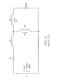
- FIG. 2 depicts an equivalent circuit for a ram air fan motor
- FIG. 3 depicts an equivalent circuit for a ram air fan motor
- FIGS. 4A-4D depict motor winding and terminal connections for a pole-change motor, according to an example embodiment
- FIGS. 5A-5D depict motor winding and terminal connections for a pole-change motor, according to an example embodiment
- FIG. 6 depicts an equivalent circuit for a pole-change motor
- FIG. 7 depicts a ram air fan control system, according to an example embodiment.
- FIG. 8 depicts a ram air fan control system, according to an example embodiment.
- Example embodiments of the present invention provide ram air fan control systems of reduced weight and increased efficiency compared to conventional systems.
- Example embodiments may include novel pole-change motor configurations to facilitate both high and low-speed operation of pole-change motors within an aircraft while maintaining similar operating frequencies and voltages at separate power controllers.
- FIGS. 4A-4D a motor winding and terminal connection diagram for a YY/Y configured pole change motor 401 are illustrated. As shown in FIGS. 4A and 4D , the pole change motor 401 includes midpoint taps at each phase winding.
- terminal connections 2U, 2V, and 2W are connected to three phase power denoted by phases A, B, and C, thereby allowing power to be applied at associated poles.
- terminal connections 1U, 1V, and 1W are also connected to phases A, B, and C, thereby allowing power to be applied at associated poles.
- the windings are connected as two Y's in parallel such that there is a maximum number of poles made available, thereby allowing high-speed operation of the motor 401.
- terminal connections 2U, 2V, and 2W are connected to three phase power denoted by phases A, B, and C, thereby allowing power to be applied at associated poles.
- terminal connections 1U, 1V, and 1W are not connected to phases A, B, and C.
- the windings are connected as a single Y such that there is a minimal number of poles made available, thereby allowing low-speed operation of the motor 401.
- Example embodiments should not be limited to only YY/Y configured pole change motors, however.
- FIGS. 5A-5D a motor winding and terminal connection diagram for a YY/ ⁇ configured pole change motor 501 are illustrated. As shown in FIGS. 5A and 5D , the pole change motor 501 includes midpoint taps at each phase winding.
- terminal connections 2X, 2Y, and 2Z are not connected to three phase power denoted by phases A, B, and C. Further, terminal connections 1X, 1Y, and 1Z are connected to phases A, B, and C, thereby allowing power to be applied at associated poles. In this configuration, there is a minimal number of poles made available, thereby allowing low-speed operation of the motor 501.
- terminal connections 2X, 2Y, and 2Z are connected to three phase power denoted by phases A, B, and C, thereby allowing power to be applied at associated poles.
- terminal connections 1X, 1Y, and 1Z are also connected to phases A, B, and C, thereby allowing power to be applied at associated poles. In this configuration, there is a maximum number of poles made available, thereby allowing high-speed operation of the motor 501.
- FIG. 6 an equivalent circuit for a YY/Y configured pole change motor, driven at low speed (see FIGS. 4C-4D ), is illustrated.
- FIG. 6 is described with reference to a YY/Y pole change motor and associated connections only, it should be understood that any other suitable pole-change configuration is also applicable.
- the ratio between magnetizing current and load current of the motor 401 is now the same as that of a low-speed rated condition, and the same full motor terminal voltage as would be applied in a high-speed condition is applied such that the current is significantly reduced.
- the net result is a relatively smaller and lighter motor controller and contactor are needed to drive the motor 401 when compared to motor controller 103 and contactor 105 of FIG. 1 .
- the parameters in the equivalent circuit depicted in FIG. 6 include a winding factor which is unchanged for the two configurations of low-speed and high-speed.
- the winding factor includes pole pitch effects and winding distribution effects along armature slots of the motor 401.
- pitch of the windings cannot be optimized for both pole counts due to the winding distribution factor being different for different pole counts.
- one possible motor design may have a half pitch, 60-degree winding distribution for a low pole count, and have a full pitch, 120-degree winding distribution for a high pole count.
- Equation 4 T 2 T 1 ⁇ B 2 B 1 ⁇ k P 2 P 1 ⁇ B 2 B 1 * p 1 p 2 ⁇ 1 2 * k
- the maximum available torque and power are above what may be required for a fan-type of load, or for example, a ram air fan load.
- the pole change control of induction motors may also be implemented with a YY/ ⁇ type of motor connected as shown in FIGS. 5A-5D .
- example embodiments provide pole change motor systems which may be of reduced weight as compared to conventional induction motor systems arising from smaller motor controllers and contactors being necessary to provide control and power to induction motors.
- example systems are described with reference to FIGS. 7-8 .
- FIG. 7 is a ram air fan motor control system, according to an example embodiment.
- the system 700 includes a ram air fan motor controller (RFMC) 701.
- the RFMC 701 may be a relatively small power controller configured to address low-power applications for a ram air fan.
- the RFMC 701 may be configured to provide power to ram air fan motors during scenarios where the ram air fans should be driven at low-speed, or situations where other power controllers are providing power to more essential aircraft systems.
- the system 700 further includes ram air fan contactor 711 operatively connected to RFMC 701.
- the contactor 711 may be closed in response to a condition where a ram air fan should be driven at low-speed, as described above.
- the system 700 may further include conductor bus 712 operatively connected to the contactor 711.
- the conductor bus 712 may be a conductor bus with conductors sized to adequately provide power to a ram air fan motor operating in a low-speed configuration.
- the system 700 may further include ram air fan (RAF) 703 operatively connected to the contactor 711 over the conductor bus 712.
- the RAF 703 may include any pole change induction motor configured to drive a ram air fan. Further, the pole change motor may be in any configuration, including a YY/Y and YY/ ⁇ configuration.
- the system 700 further includes contactor 704 operatively connected to RAF 703.
- the contactor 704 may be configured to open in response to a condition where the RAF 703 should be disconnected / powered down completely.
- the system 700 further includes common power controller (CMC) 702.
- the CMC 702 may be a relatively large power controller configured to address power applications for a large portion or entirety of an aircraft.
- the CMC 702 may be configured to provide power to essential and non-essential aircraft systems.
- the system 700 further includes ram air fan contactor 721 operatively connected to CMC 702.
- the contactor 721 may be closed in response to a condition where a ram air fan should be driven at high-speed, as described above.
- the system 700 may further include conductor bus 722 operatively connected to the contactor 721.
- the conductor bus 722 may be a conductor bus with conductors sized to adequately provide power to a ram air fan motor operating in a high-speed configuration.
- the conductor bus 722 is separate and electrically isolated from the conductor bus 712.
- the RAF 703 is operatively connected to the contactor 721 over the conductor bus 722.
- the system 700 may be applicable to aircraft where an additional conductor bus for low-speed operation of a ram air fan is desirable, and would necessitate a relatively small number of contactors.
- an alternative system is described with reference to FIG. 8 .
- FIG. 8 is a ram air fan motor control system, according to an example embodiment.
- the system 800 includes a ram air fan motor controller (RFMC) 801.
- the RFMC 801 may be a relatively small power controller configured to address low-power applications for a ram air fan.
- the RFMC 801 may be configured to provide power to ram air fan motors during scenarios where the ram air fans should be driven at low-speed, or situations where other power controllers are providing power to more essential aircraft systems.
- the system 800 further includes ram air fan contactor 811 operatively connected to RFMC 801.
- the contactor 811 may be closed in response to a condition where a ram air fan should be driven at low-speed, as described above.
- the system 800 may further include conductor bus 822 operatively connected to the contactor 811.
- the conductor bus 822 may be a conductor bus with conductors sized to adequately provide power to a ram air fan motor operating in both a high-speed configuration and a low-speed configuration.
- the system 800 necessitates a single conductor bus to power a ram air fan in both desired configurations.
- the system 800 further includes contactor 805 operatively connected to the contactor 811 over the conductor bus 822.
- the contactor 805 may be configured to close in response to a condition where a ram air fan should be driven at low-speed, as described above.
- the system 800 may further include ram air fan (RAF) 803 operatively connected to the contactor 805.
- the RAF 803 may include any pole change induction motor configured to drive a ram air fan.
- the pole change motor may be in any configuration, including a YY/Y and YY/ ⁇ configuration.
- the system 800 further includes contactor 804 operatively connected to RAF 803.
- the contactor 804 may be configured to open in response to a condition where the RAF 803 should be disconnected / powered down completely.
- the system 800 further includes common power controller (CMC) 802.
- the CMC 802 may be a relatively large power controller configured to address power applications for a large portion or entirety of an aircraft.
- the CMC 802 may be configured to provide power to essential and non-essential aircraft systems.
- the system 800 further includes ram air fan contactor 821 operatively connected to CMC 802.
- the contactor 821 may be closed in response to a condition where a ram air fan should be driven at high-speed, as described above.
- the system 800 further includes contactor 806 operatively connected to the contactor 821 over conductor bus 822.
- the contactor 806 may be closed in response to a condition where a ram air fan should be driven at high-speed, as described above.
- the RAF 803 is operatively connected to the contactor 806 and subsequently to the contactor 821 over the conductor bus 822. Therefore, if contactors 821 and 806 are both closed, the RAF 803 may operate in a high-speed configuration. Alternatively, if both the contactors 811 and 805 are closed, the RAF 803 may operate in a low-speed configuration. However, in contrast to the system 700, both configurations may be available over a common conductor bus 822.
- system 800 may be applicable to aircraft where a single conductor bus for both low-speed and high-speed operation of a ram air fan is desirable, and would necessitate a plurality of contactors 805-806 to facilitate pole changing of the RAF 803.
- example embodiments include relatively reduced weight of ram air fan control systems on an aircraft.
- a ram air fan motor Through changing poles on a ram air fan motor to facilitate a low-speed operating condition with lower current than conventional systems, smaller contactors are necessary to facilitate both high and low-speed operation, resulting in lower overall weight of the ram air fan control system.
- a pole change motor for a ram air fan both a common motor controller and a ram air fan motor controller operate at substantially the same output voltage and frequency.
Landscapes
- Engineering & Computer Science (AREA)
- Power Engineering (AREA)
- Control Of Multiple Motors (AREA)
Abstract
Description
- The subject matter disclosed herein relates generally to the field of pole change induction motors, and more particularly to the use and control of pole change induction motors in ram air fan systems.
- Conventionally, an induction motor may be driven through a motor controller. As illustrated in
FIG. 1 , a ram air fan motor (RAF) 101 is normally driven bycommon motor controller 102 at high speed and high power. If thecommon motor controller 102 is not available, RAFmotor controller 103 is used to power the RAF 101 at low speed and low power. The switch-over may be accomplished by controlling interlocked contactors (or relays/breakers) 104 and 105. Bothcontactors motor controllers - The RAF 101 is located remote from the motor controller panel where motor controllers 102-103 and the contactors 104-105 are located. Three phase power is fed to the RAF 101 through high current motor feeder /
conductor bus 106. - The equivalent circuit of the
RAF motor 101 when driven byCMC 102 is shown inFIG. 2 . IL is the load current that produces the motor torque, while Im is the magnetizing current in the motor. This high-speed, high-power operating condition is the rated condition the motor is designed to operate, hence resulting in a higher power factor and efficiency. - However, if the RAF 101 is driven by
controller 102 at about half the rated speed (seeFIG. 3 ), the load torque, and hence the load current, is reduced to about 1/4 of rated load current, while magnetizing current Im remains more or less the same as that in the motor's rated condition. Hence the magnetizing current becomes a very significant part of the overall current, and the power factor becomes very low. - In addition to the excessive magnetizing current relative to the low load current, the operation of
RAF motor 101 at low speed and low terminal voltage with higher current further reduces the efficiency of theRAF motor 101 as well as themotor controller 103. The inefficient, low power factor and low terminal voltage operating condition of theRAF 101 results in the necessity of a relatively large rating and weight forcontactor 105. - According to one aspect of the invention, a ram air fan control system includes a ram air fan motor, the ram air fan motor being a pole-change induction motor with at least two pole-count configurations, a ram air fan contactor in operative communication with a first pole-count configuration of the ram air fan motor over a ram air fan conductor bus, a ram air fan power controller in operative communication with the ram air fan contactor, a common contactor in operative communication with a second pole-count configuration of the ram air fan motor over a common conductor bus, the common conductor bus being separate and electrically isolated from the ram air fan conductor bus, and a common power controller in operative communication with the common contactor.
- According to another aspect of the invention, a ram air fan control system includes a ram air fan motor, the ram air fan motor being a pole-change induction motor with at least two pole-count configurations, a first ram air fan contactor in operative communication with a first pole-count configuration of the ram air fan motor, a conductor bus in operative communication with the first ram air fan contactor, a second ram air fan contactor in operative communication with the first ram air fan contactor over the conductor bus, a ram air fan power controller in operative communication with the second ram air fan contactor, a first common contactor in operative communication with a second pole-count configuration of the ram air fan motor, a second common contactor in operative communication with the first common contactor over the conductor bus, and a common power controller in operative communication with the common contactor.
- Other aspects, features, and techniques of the invention will become more apparent from the following description taken in conjunction with the drawings.
- Referring now to the drawings wherein like elements are numbered alike in the several FIGURES:
-
FIG. 1 depicts a conventional ram air fan control system; -
FIG. 2 depicts an equivalent circuit for a ram air fan motor; -
FIG. 3 depicts an equivalent circuit for a ram air fan motor; -
FIGS. 4A-4D depict motor winding and terminal connections for a pole-change motor, according to an example embodiment; -
FIGS. 5A-5D depict motor winding and terminal connections for a pole-change motor, according to an example embodiment; -
FIG. 6 depicts an equivalent circuit for a pole-change motor; -
FIG. 7 depicts a ram air fan control system, according to an example embodiment; and -
FIG. 8 depicts a ram air fan control system, according to an example embodiment. - Example embodiments of the present invention provide ram air fan control systems of reduced weight and increased efficiency compared to conventional systems. Example embodiments may include novel pole-change motor configurations to facilitate both high and low-speed operation of pole-change motors within an aircraft while maintaining similar operating frequencies and voltages at separate power controllers.
- Turning to
FIGS. 4A-4D , a motor winding and terminal connection diagram for a YY/Y configuredpole change motor 401 are illustrated. As shown inFIGS. 4A and 4D , thepole change motor 401 includes midpoint taps at each phase winding. - Turning to
FIGS. 4A-4B , high-speed motor winding and terminal connections are illustrated. As shown,terminal connections terminal connections motor 401. - Turning to
FIGS. 4C and 4D , low-speed motor winding and terminal connections are illustrated. As shown,terminal connections terminal connections motor 401. - Example embodiments should not be limited to only YY/Y configured pole change motors, however.
- Turning to
FIGS. 5A-5D , a motor winding and terminal connection diagram for a YY/Δ configuredpole change motor 501 are illustrated. As shown inFIGS. 5A and 5D , thepole change motor 501 includes midpoint taps at each phase winding. - Turning to
FIGS. 5A-5B , low-speed motor winding and terminal connections are illustrated. As shown,terminal connections terminal connections motor 501. - Turning to
FIGS. 5C and 5D , high-speed motor winding and terminal connections are illustrated. As shown,terminal connections terminal connections motor 501. - Turning to
FIG. 6 , an equivalent circuit for a YY/Y configured pole change motor, driven at low speed (seeFIGS. 4C-4D ), is illustrated. Although the example ofFIG. 6 is described with reference to a YY/Y pole change motor and associated connections only, it should be understood that any other suitable pole-change configuration is also applicable. - According to
FIG. 6 , the ratio between magnetizing current and load current of themotor 401 is now the same as that of a low-speed rated condition, and the same full motor terminal voltage as would be applied in a high-speed condition is applied such that the current is significantly reduced. The net result is a relatively smaller and lighter motor controller and contactor are needed to drive themotor 401 when compared tomotor controller 103 andcontactor 105 ofFIG. 1 . - For clarity of comparison, the parameters in the equivalent circuit depicted in
FIG. 6 include a winding factor which is unchanged for the two configurations of low-speed and high-speed. The winding factor includes pole pitch effects and winding distribution effects along armature slots of themotor 401. Depending upon a design of themotor 401, under the two pole count conditions ofFIGS. 4A and 4C , pitch of the windings cannot be optimized for both pole counts due to the winding distribution factor being different for different pole counts. For example, one possible motor design may have a half pitch, 60-degree winding distribution for a low pole count, and have a full pitch, 120-degree winding distribution for a high pole count. Thus, the ratio of winding factors for different pole counts would be given by Equation 1:
- The ratio of flux density after and before pole change is normally given by Equation 2:

- For the YY/Y type
pole change motor 401, the windings are connected as two "Y's" in parallel for high-speed operation, and connected as a single "Y" for low-speed operation. Thus, the ratio of flux density after and before pole change formotor 401 is given by Equation 3:
- Hence the ratio of maximum available torque and maximum available power are given by
Equations 4 and 5:

- The maximum available torque and power are above what may be required for a fan-type of load, or for example, a ram air fan load.
- The pole change control of induction motors according to example embodiments of the present invention may also be implemented with a YY/Δ type of motor connected as shown in
FIGS. 5A-5D . - As described above, example embodiments provide pole change motor systems which may be of reduced weight as compared to conventional induction motor systems arising from smaller motor controllers and contactors being necessary to provide control and power to induction motors. Hereinafter, example systems are described with reference to
FIGS. 7-8 . -
FIG. 7 is a ram air fan motor control system, according to an example embodiment. As illustrated, thesystem 700 includes a ram air fan motor controller (RFMC) 701. TheRFMC 701 may be a relatively small power controller configured to address low-power applications for a ram air fan. For example, theRFMC 701 may be configured to provide power to ram air fan motors during scenarios where the ram air fans should be driven at low-speed, or situations where other power controllers are providing power to more essential aircraft systems. - The
system 700 further includes ramair fan contactor 711 operatively connected toRFMC 701. Thecontactor 711 may be closed in response to a condition where a ram air fan should be driven at low-speed, as described above. - The
system 700 may further includeconductor bus 712 operatively connected to thecontactor 711. Theconductor bus 712 may be a conductor bus with conductors sized to adequately provide power to a ram air fan motor operating in a low-speed configuration. - The
system 700 may further include ram air fan (RAF) 703 operatively connected to thecontactor 711 over theconductor bus 712. TheRAF 703 may include any pole change induction motor configured to drive a ram air fan. Further, the pole change motor may be in any configuration, including a YY/Y and YY/Δ configuration. - The
system 700 further includescontactor 704 operatively connected toRAF 703. Thecontactor 704 may be configured to open in response to a condition where theRAF 703 should be disconnected / powered down completely. - The
system 700 further includes common power controller (CMC) 702. TheCMC 702 may be a relatively large power controller configured to address power applications for a large portion or entirety of an aircraft. For example, theCMC 702 may be configured to provide power to essential and non-essential aircraft systems. - The
system 700 further includes ramair fan contactor 721 operatively connected toCMC 702. Thecontactor 721 may be closed in response to a condition where a ram air fan should be driven at high-speed, as described above. - The
system 700 may further includeconductor bus 722 operatively connected to thecontactor 721. Theconductor bus 722 may be a conductor bus with conductors sized to adequately provide power to a ram air fan motor operating in a high-speed configuration. Theconductor bus 722 is separate and electrically isolated from theconductor bus 712. As illustrated, theRAF 703 is operatively connected to thecontactor 721 over theconductor bus 722. - The
system 700 may be applicable to aircraft where an additional conductor bus for low-speed operation of a ram air fan is desirable, and would necessitate a relatively small number of contactors. Hereinafter, an alternative system is described with reference toFIG. 8 . -
FIG. 8 is a ram air fan motor control system, according to an example embodiment. As illustrated, thesystem 800 includes a ram air fan motor controller (RFMC) 801. TheRFMC 801 may be a relatively small power controller configured to address low-power applications for a ram air fan. For example, theRFMC 801 may be configured to provide power to ram air fan motors during scenarios where the ram air fans should be driven at low-speed, or situations where other power controllers are providing power to more essential aircraft systems. - The
system 800 further includes ramair fan contactor 811 operatively connected toRFMC 801. Thecontactor 811 may be closed in response to a condition where a ram air fan should be driven at low-speed, as described above. - The
system 800 may further includeconductor bus 822 operatively connected to thecontactor 811. Theconductor bus 822 may be a conductor bus with conductors sized to adequately provide power to a ram air fan motor operating in both a high-speed configuration and a low-speed configuration. Thus, in contrast to thesystem 700, thesystem 800 necessitates a single conductor bus to power a ram air fan in both desired configurations. - The
system 800 further includescontactor 805 operatively connected to thecontactor 811 over theconductor bus 822. Thecontactor 805 may be configured to close in response to a condition where a ram air fan should be driven at low-speed, as described above. - The
system 800 may further include ram air fan (RAF) 803 operatively connected to thecontactor 805. TheRAF 803 may include any pole change induction motor configured to drive a ram air fan. Further, the pole change motor may be in any configuration, including a YY/Y and YY/Δ configuration. - The
system 800 further includescontactor 804 operatively connected toRAF 803. Thecontactor 804 may be configured to open in response to a condition where theRAF 803 should be disconnected / powered down completely. - The
system 800 further includes common power controller (CMC) 802. TheCMC 802 may be a relatively large power controller configured to address power applications for a large portion or entirety of an aircraft. For example, theCMC 802 may be configured to provide power to essential and non-essential aircraft systems. - The
system 800 further includes ramair fan contactor 821 operatively connected toCMC 802. Thecontactor 821 may be closed in response to a condition where a ram air fan should be driven at high-speed, as described above. - The
system 800 further includescontactor 806 operatively connected to thecontactor 821 overconductor bus 822. Thecontactor 806 may be closed in response to a condition where a ram air fan should be driven at high-speed, as described above. - As illustrated, the
RAF 803 is operatively connected to thecontactor 806 and subsequently to thecontactor 821 over theconductor bus 822. Therefore, ifcontactors RAF 803 may operate in a high-speed configuration. Alternatively, if both thecontactors RAF 803 may operate in a low-speed configuration. However, in contrast to thesystem 700, both configurations may be available over acommon conductor bus 822. - Thus, the
system 800 may be applicable to aircraft where a single conductor bus for both low-speed and high-speed operation of a ram air fan is desirable, and would necessitate a plurality of contactors 805-806 to facilitate pole changing of theRAF 803. - The technical effects and benefits of example embodiments include relatively reduced weight of ram air fan control systems on an aircraft. Through changing poles on a ram air fan motor to facilitate a low-speed operating condition with lower current than conventional systems, smaller contactors are necessary to facilitate both high and low-speed operation, resulting in lower overall weight of the ram air fan control system. Furthermore, through the use of a pole change motor for a ram air fan, both a common motor controller and a ram air fan motor controller operate at substantially the same output voltage and frequency.
- The terminology used herein is for the purpose of describing particular embodiments only and is not intended to be limiting of the invention. While the description of the present invention has been presented for purposes of illustration and description, it is not intended to be exhaustive or limited to the invention in the form disclosed. Many modifications, variations, alterations, substitutions, or equivalent arrangement not hereto described will be apparent to those of ordinary skill in the art without departing from the scope of the invention, which is defined by the claims. Additionally, while various embodiment of the invention have been described, it is to be understood that aspects of the invention may include only some of the described embodiments. Accordingly, the invention is not to be seen as limited by the foregoing description, but is only limited by the scope of the appended claims.
Claims (11)
- A ram air fan control system (700;800), comprising:a ram air fan motor (703;803), the ram air fan motor being a pole-change induction motor (401;501) with at least two pole-count configurations;a ram air fan contactor (711;811,805) in operative communication with a first pole-count configuration of the ram air fan motor over a conductor bus (712,822);a ram air fan power controller (701,801) in operative communication with the ram air fan contactor;a common contactor (721;821,806) in operative communication with a second pole-count configuration of the ram air fan motor over a second conductor bus (722) or the conductor bus (822); anda common power controller (702,802) in operative communication with the common contactor (721;821,806);wherein either:the ram air fan contactor (711) is in operative communication with the first pole-count configuration of the ram air fan motor over a first conductor bus (712) and the common contactor (721) is in operative communication with the second pole-count configuration of the ram air fan motor over a second conductor bus (722), which is separate and electrically isolated from the first conductor bus (712);
or:the ram air fan contactor (811,805) that is in operative communication with a first pole-count configuration of the ram air fan motor comprises a first ram air fan contactor (811) and a second ram air fan contactor (805) in operative communication with the first ram air fan contactor over the conductor bus (822), with the ram air fan power controller (801) being in operative communication with the second ram air fan contactor (805) and connecting to the first ram air fan contactor (811) via second ram air fan contactor (805) and the conductor bus (822), and the common contactor (821,806) that is in operative communication with the second pole-count configuration of the ram air fan motor comprises a first common contactor (821) and a second common contactor (806) in operative communication with the first common contactor over the conductor bus. - The system of claim 1, wherein the ram air fan motor is a YY/Y pole-change motor (401).
- The system of claim 2, wherein the first pole-count configuration is a configuration where windings of the ram air fan motor are connected as a single Y.
- The system of claim 3, wherein the first pole-count configuration is a low-speed configuration for operation of the ram air fan motor at low-speed.
- The system of claim 2, wherein the second pole-count configuration is a configuration where windings of the ram air fan motor are connected as two Y's in parallel.
- The system of claim 5, wherein the second pole-count configuration is a high-speed configuration for operation of the ram air fan motor at high-speed.
- The system of claim 1, wherein the first pole-count configuration is a low-speed configuration with less poles than the second pole-count configuration.
- The system of claim 1, wherein the second pole-count configuration is a high-speed configuration with more poles than the first pole-count configuration.
- The system of claim 1, comprising first and second conductor buses (712, 722), wherein the ram air fan contactor is of a lower current rating than the common contactor, and the first conductor bus is of a lower current rating than the second conductor bus.
- The system of claim 1, wherein the ram air fan motor is a pole-change motor with midpoint tapped windings.
- The system of claim 1, wherein the ram air fan contactor is of a lower current rating than the common contactor, and the conductor bus is of a current rating at least as high as the common contactor.
Applications Claiming Priority (1)
| Application Number | Priority Date | Filing Date | Title |
|---|---|---|---|
| US12/858,764 US8294409B2 (en) | 2010-08-18 | 2010-08-18 | Control of pole-change induction motors |
Publications (3)
| Publication Number | Publication Date |
|---|---|
| EP2432116A2 true EP2432116A2 (en) | 2012-03-21 |
| EP2432116A3 EP2432116A3 (en) | 2015-07-29 |
| EP2432116B1 EP2432116B1 (en) | 2020-04-08 |
Family
ID=44532666
Family Applications (1)
| Application Number | Title | Priority Date | Filing Date |
|---|---|---|---|
| EP11177683.7A Active EP2432116B1 (en) | 2010-08-18 | 2011-08-16 | Control of pole-change induction motors |
Country Status (2)
| Country | Link |
|---|---|
| US (1) | US8294409B2 (en) |
| EP (1) | EP2432116B1 (en) |
Families Citing this family (2)
| Publication number | Priority date | Publication date | Assignee | Title |
|---|---|---|---|---|
| DE102014006028B4 (en) * | 2014-04-24 | 2022-06-30 | Audi Ag | Multi-battery system to increase the electric range |
| US10137981B2 (en) | 2017-03-31 | 2018-11-27 | General Electric Company | Electric propulsion system for an aircraft |
Family Cites Families (19)
| Publication number | Priority date | Publication date | Assignee | Title |
|---|---|---|---|---|
| US4064420A (en) * | 1975-04-18 | 1977-12-20 | Matsushita Electric Industrial Co., Ltd. | Control system for pole-changing-motor-driven compressor |
| US4370605A (en) * | 1980-09-02 | 1983-01-25 | Westinghouse Electric Corp. | Two-speed motor control |
| US4546939A (en) * | 1982-05-27 | 1985-10-15 | Lockheed Corporation | Energy efficient ECS powered by a variable voltage/variable frequency power system |
| KR890001325B1 (en) | 1983-06-28 | 1989-04-29 | 미쓰비시전기 주식회사 | Boiler air flow controlling apparatus |
| JPS6032596A (en) | 1983-07-30 | 1985-02-19 | Mitsubishi Electric Corp | Control system of pole change motor |
| JPH0665926B2 (en) | 1983-07-30 | 1994-08-24 | 三菱電機株式会社 | Air volume control method |
| US4967096A (en) * | 1989-01-26 | 1990-10-30 | Sundstrand Corporation | Cross-start bus configuration for a variable speed constant frequency electric power system |
| US5031573A (en) | 1990-02-22 | 1991-07-16 | Marco Peter F De | Transportation container for laboratory animals |
| JP3399134B2 (en) * | 1994-12-12 | 2003-04-21 | 株式会社明電舎 | Operation control device for pole number switching motor |
| US5704218A (en) | 1996-04-08 | 1998-01-06 | United Technologies Corporation | Integrated environmental control system |
| US5880571A (en) * | 1997-09-11 | 1999-03-09 | Sundstrand Corporation | Method of and system for controlling a variable speed induction motor |
| JP2001327132A (en) * | 2000-05-18 | 2001-11-22 | Mitsubishi Electric Corp | Induction motor with pole number switching |
| KR100400737B1 (en) | 2000-09-18 | 2003-10-08 | 엘지전자 주식회사 | Pole change motor |
| US6681592B1 (en) | 2001-02-16 | 2004-01-27 | Hamilton Sundstrand Corporation | Electrically driven aircraft cabin ventilation and environmental control system |
| US7210653B2 (en) * | 2002-10-22 | 2007-05-01 | The Boeing Company | Electric-based secondary power system architectures for aircraft |
| US20050151019A1 (en) * | 2003-12-18 | 2005-07-14 | Curtis Edgar Stevens | Electrically pressurized on-board inert gas generation system |
| US7757502B2 (en) | 2004-09-22 | 2010-07-20 | Hamilton Sundstrand Corporation | RAM fan system for an aircraft environmental control system |
| US7513119B2 (en) * | 2005-02-03 | 2009-04-07 | The Boeing Company | Systems and methods for starting aircraft engines |
| CN101395032B (en) * | 2006-12-27 | 2011-11-09 | 三菱电机株式会社 | Drive control device for electrically driven vehicles |
-
2010
- 2010-08-18 US US12/858,764 patent/US8294409B2/en not_active Expired - Fee Related
-
2011
- 2011-08-16 EP EP11177683.7A patent/EP2432116B1/en active Active
Non-Patent Citations (1)
| Title |
|---|
| None |
Also Published As
| Publication number | Publication date |
|---|---|
| US20120043921A1 (en) | 2012-02-23 |
| EP2432116A3 (en) | 2015-07-29 |
| US8294409B2 (en) | 2012-10-23 |
| EP2432116B1 (en) | 2020-04-08 |
Similar Documents
| Publication | Publication Date | Title |
|---|---|---|
| US9800193B2 (en) | Dynamically reconfigurable motors and generators and systems | |
| US8928264B2 (en) | Control device for rotating electrical machine | |
| CN107017673B (en) | Voltage disconnect structure | |
| US20140239876A1 (en) | Electric drive with reconfigurable winding | |
| US8907628B2 (en) | Automotive bipolar electrical system | |
| US20130334998A1 (en) | Systems, apparatus, and methods for soft starting large ac motors with a variable frequency drive | |
| US10924027B2 (en) | Switching power supply device | |
| JPH07298682A (en) | Method and apparatus for reducing voltage induced in induction motor | |
| US20210152108A1 (en) | Electric Winding Exchanger System | |
| JPS6032596A (en) | Control system of pole change motor | |
| EP2432116B1 (en) | Control of pole-change induction motors | |
| CN108715140B (en) | Electronic gear shifting system adopting variable winding permanent magnet synchronous motor | |
| EP2044684B3 (en) | Variable voltage supply system | |
| CN102281030A (en) | Triangle-star (Y) starting method of low power, asynchronous starting and permanent-magnet synchronous motor | |
| US11355973B2 (en) | Direct current motor | |
| Raminosoa et al. | Fault tolerant winding technology comparison for flux switching machine | |
| US11211855B2 (en) | Direct current motor | |
| CN1976179A (en) | Three-phase wound-rotor induction motor | |
| CN110518770A (en) | A kind of series DC machine | |
| CA2519968A1 (en) | Electric generator for vehicle producing dual output voltages | |
| EP3255779B1 (en) | Reconfigurable multi-permanent magnet generator based power generating system | |
| Matoso et al. | Using Field-Oriented Control and Hysteresis Current Control to Obtain a Small Zero-Sequence Current in an Open-End Winding Induction Motor Drive | |
| EP4629503A1 (en) | Reconfigurable synchronous machine | |
| US12451827B2 (en) | Variable frequency drive system with medium voltage input and low voltage output | |
| WO2022137532A1 (en) | Power supply circuit |
Legal Events
| Date | Code | Title | Description |
|---|---|---|---|
| PUAI | Public reference made under article 153(3) epc to a published international application that has entered the european phase |
Free format text: ORIGINAL CODE: 0009012 |
|
| AK | Designated contracting states |
Kind code of ref document: A2 Designated state(s): AL AT BE BG CH CY CZ DE DK EE ES FI FR GB GR HR HU IE IS IT LI LT LU LV MC MK MT NL NO PL PT RO RS SE SI SK SM TR |
|
| AX | Request for extension of the european patent |
Extension state: BA ME |
|
| PUAL | Search report despatched |
Free format text: ORIGINAL CODE: 0009013 |
|
| AK | Designated contracting states |
Kind code of ref document: A3 Designated state(s): AL AT BE BG CH CY CZ DE DK EE ES FI FR GB GR HR HU IE IS IT LI LT LU LV MC MK MT NL NO PL PT RO RS SE SI SK SM TR |
|
| AX | Request for extension of the european patent |
Extension state: BA ME |
|
| RIC1 | Information provided on ipc code assigned before grant |
Ipc: H02P 25/20 20060101AFI20150623BHEP |
|
| 17P | Request for examination filed |
Effective date: 20160129 |
|
| RBV | Designated contracting states (corrected) |
Designated state(s): AL AT BE BG CH CY CZ DE DK EE ES FI FR GB GR HR HU IE IS IT LI LT LU LV MC MK MT NL NO PL PT RO RS SE SI SK SM TR |
|
| STAA | Information on the status of an ep patent application or granted ep patent |
Free format text: STATUS: EXAMINATION IS IN PROGRESS |
|
| 17Q | First examination report despatched |
Effective date: 20181017 |
|
| GRAP | Despatch of communication of intention to grant a patent |
Free format text: ORIGINAL CODE: EPIDOSNIGR1 |
|
| STAA | Information on the status of an ep patent application or granted ep patent |
Free format text: STATUS: GRANT OF PATENT IS INTENDED |
|
| INTG | Intention to grant announced |
Effective date: 20190522 |
|
| GRAJ | Information related to disapproval of communication of intention to grant by the applicant or resumption of examination proceedings by the epo deleted |
Free format text: ORIGINAL CODE: EPIDOSDIGR1 |
|
| STAA | Information on the status of an ep patent application or granted ep patent |
Free format text: STATUS: EXAMINATION IS IN PROGRESS |
|
| GRAP | Despatch of communication of intention to grant a patent |
Free format text: ORIGINAL CODE: EPIDOSNIGR1 |
|
| STAA | Information on the status of an ep patent application or granted ep patent |
Free format text: STATUS: GRANT OF PATENT IS INTENDED |
|
| INTC | Intention to grant announced (deleted) | ||
| INTG | Intention to grant announced |
Effective date: 20191025 |
|
| GRAS | Grant fee paid |
Free format text: ORIGINAL CODE: EPIDOSNIGR3 |
|
| GRAA | (expected) grant |
Free format text: ORIGINAL CODE: 0009210 |
|
| STAA | Information on the status of an ep patent application or granted ep patent |
Free format text: STATUS: THE PATENT HAS BEEN GRANTED |
|
| AK | Designated contracting states |
Kind code of ref document: B1 Designated state(s): AL AT BE BG CH CY CZ DE DK EE ES FI FR GB GR HR HU IE IS IT LI LT LU LV MC MK MT NL NO PL PT RO RS SE SI SK SM TR |
|
| RAP1 | Party data changed (applicant data changed or rights of an application transferred) |
Owner name: HAMILTON SUNDSTRAND CORPORATION |
|
| REG | Reference to a national code |
Ref country code: GB Ref legal event code: FG4D |
|
| REG | Reference to a national code |
Ref country code: CH Ref legal event code: EP Ref country code: AT Ref legal event code: REF Ref document number: 1255719 Country of ref document: AT Kind code of ref document: T Effective date: 20200415 |
|
| REG | Reference to a national code |
Ref country code: DE Ref legal event code: R096 Ref document number: 602011066096 Country of ref document: DE |
|
| REG | Reference to a national code |
Ref country code: IE Ref legal event code: FG4D |
|
| REG | Reference to a national code |
Ref country code: NL Ref legal event code: MP Effective date: 20200408 |
|
| REG | Reference to a national code |
Ref country code: LT Ref legal event code: MG4D |
|
| PG25 | Lapsed in a contracting state [announced via postgrant information from national office to epo] |
Ref country code: PT Free format text: LAPSE BECAUSE OF FAILURE TO SUBMIT A TRANSLATION OF THE DESCRIPTION OR TO PAY THE FEE WITHIN THE PRESCRIBED TIME-LIMIT Effective date: 20200817 Ref country code: NO Free format text: LAPSE BECAUSE OF FAILURE TO SUBMIT A TRANSLATION OF THE DESCRIPTION OR TO PAY THE FEE WITHIN THE PRESCRIBED TIME-LIMIT Effective date: 20200708 Ref country code: IS Free format text: LAPSE BECAUSE OF FAILURE TO SUBMIT A TRANSLATION OF THE DESCRIPTION OR TO PAY THE FEE WITHIN THE PRESCRIBED TIME-LIMIT Effective date: 20200808 Ref country code: FI Free format text: LAPSE BECAUSE OF FAILURE TO SUBMIT A TRANSLATION OF THE DESCRIPTION OR TO PAY THE FEE WITHIN THE PRESCRIBED TIME-LIMIT Effective date: 20200408 Ref country code: LT Free format text: LAPSE BECAUSE OF FAILURE TO SUBMIT A TRANSLATION OF THE DESCRIPTION OR TO PAY THE FEE WITHIN THE PRESCRIBED TIME-LIMIT Effective date: 20200408 Ref country code: GR Free format text: LAPSE BECAUSE OF FAILURE TO SUBMIT A TRANSLATION OF THE DESCRIPTION OR TO PAY THE FEE WITHIN THE PRESCRIBED TIME-LIMIT Effective date: 20200709 Ref country code: SE Free format text: LAPSE BECAUSE OF FAILURE TO SUBMIT A TRANSLATION OF THE DESCRIPTION OR TO PAY THE FEE WITHIN THE PRESCRIBED TIME-LIMIT Effective date: 20200408 Ref country code: NL Free format text: LAPSE BECAUSE OF FAILURE TO SUBMIT A TRANSLATION OF THE DESCRIPTION OR TO PAY THE FEE WITHIN THE PRESCRIBED TIME-LIMIT Effective date: 20200408 |
|
| REG | Reference to a national code |
Ref country code: AT Ref legal event code: MK05 Ref document number: 1255719 Country of ref document: AT Kind code of ref document: T Effective date: 20200408 |
|
| PG25 | Lapsed in a contracting state [announced via postgrant information from national office to epo] |
Ref country code: BG Free format text: LAPSE BECAUSE OF FAILURE TO SUBMIT A TRANSLATION OF THE DESCRIPTION OR TO PAY THE FEE WITHIN THE PRESCRIBED TIME-LIMIT Effective date: 20200708 Ref country code: LV Free format text: LAPSE BECAUSE OF FAILURE TO SUBMIT A TRANSLATION OF THE DESCRIPTION OR TO PAY THE FEE WITHIN THE PRESCRIBED TIME-LIMIT Effective date: 20200408 Ref country code: HR Free format text: LAPSE BECAUSE OF FAILURE TO SUBMIT A TRANSLATION OF THE DESCRIPTION OR TO PAY THE FEE WITHIN THE PRESCRIBED TIME-LIMIT Effective date: 20200408 Ref country code: RS Free format text: LAPSE BECAUSE OF FAILURE TO SUBMIT A TRANSLATION OF THE DESCRIPTION OR TO PAY THE FEE WITHIN THE PRESCRIBED TIME-LIMIT Effective date: 20200408 |
|
| PG25 | Lapsed in a contracting state [announced via postgrant information from national office to epo] |
Ref country code: AL Free format text: LAPSE BECAUSE OF FAILURE TO SUBMIT A TRANSLATION OF THE DESCRIPTION OR TO PAY THE FEE WITHIN THE PRESCRIBED TIME-LIMIT Effective date: 20200408 |
|
| REG | Reference to a national code |
Ref country code: DE Ref legal event code: R097 Ref document number: 602011066096 Country of ref document: DE |
|
| PG25 | Lapsed in a contracting state [announced via postgrant information from national office to epo] |
Ref country code: DK Free format text: LAPSE BECAUSE OF FAILURE TO SUBMIT A TRANSLATION OF THE DESCRIPTION OR TO PAY THE FEE WITHIN THE PRESCRIBED TIME-LIMIT Effective date: 20200408 Ref country code: ES Free format text: LAPSE BECAUSE OF FAILURE TO SUBMIT A TRANSLATION OF THE DESCRIPTION OR TO PAY THE FEE WITHIN THE PRESCRIBED TIME-LIMIT Effective date: 20200408 Ref country code: RO Free format text: LAPSE BECAUSE OF FAILURE TO SUBMIT A TRANSLATION OF THE DESCRIPTION OR TO PAY THE FEE WITHIN THE PRESCRIBED TIME-LIMIT Effective date: 20200408 Ref country code: IT Free format text: LAPSE BECAUSE OF FAILURE TO SUBMIT A TRANSLATION OF THE DESCRIPTION OR TO PAY THE FEE WITHIN THE PRESCRIBED TIME-LIMIT Effective date: 20200408 Ref country code: EE Free format text: LAPSE BECAUSE OF FAILURE TO SUBMIT A TRANSLATION OF THE DESCRIPTION OR TO PAY THE FEE WITHIN THE PRESCRIBED TIME-LIMIT Effective date: 20200408 Ref country code: SM Free format text: LAPSE BECAUSE OF FAILURE TO SUBMIT A TRANSLATION OF THE DESCRIPTION OR TO PAY THE FEE WITHIN THE PRESCRIBED TIME-LIMIT Effective date: 20200408 Ref country code: CZ Free format text: LAPSE BECAUSE OF FAILURE TO SUBMIT A TRANSLATION OF THE DESCRIPTION OR TO PAY THE FEE WITHIN THE PRESCRIBED TIME-LIMIT Effective date: 20200408 Ref country code: AT Free format text: LAPSE BECAUSE OF FAILURE TO SUBMIT A TRANSLATION OF THE DESCRIPTION OR TO PAY THE FEE WITHIN THE PRESCRIBED TIME-LIMIT Effective date: 20200408 |
|
| PLBE | No opposition filed within time limit |
Free format text: ORIGINAL CODE: 0009261 |
|
| STAA | Information on the status of an ep patent application or granted ep patent |
Free format text: STATUS: NO OPPOSITION FILED WITHIN TIME LIMIT |
|
| PG25 | Lapsed in a contracting state [announced via postgrant information from national office to epo] |
Ref country code: PL Free format text: LAPSE BECAUSE OF FAILURE TO SUBMIT A TRANSLATION OF THE DESCRIPTION OR TO PAY THE FEE WITHIN THE PRESCRIBED TIME-LIMIT Effective date: 20200408 Ref country code: SK Free format text: LAPSE BECAUSE OF FAILURE TO SUBMIT A TRANSLATION OF THE DESCRIPTION OR TO PAY THE FEE WITHIN THE PRESCRIBED TIME-LIMIT Effective date: 20200408 |
|
| REG | Reference to a national code |
Ref country code: DE Ref legal event code: R119 Ref document number: 602011066096 Country of ref document: DE |
|
| 26N | No opposition filed |
Effective date: 20210112 |
|
| PG25 | Lapsed in a contracting state [announced via postgrant information from national office to epo] |
Ref country code: MC Free format text: LAPSE BECAUSE OF FAILURE TO SUBMIT A TRANSLATION OF THE DESCRIPTION OR TO PAY THE FEE WITHIN THE PRESCRIBED TIME-LIMIT Effective date: 20200408 |
|
| REG | Reference to a national code |
Ref country code: CH Ref legal event code: PL |
|
| PG25 | Lapsed in a contracting state [announced via postgrant information from national office to epo] |
Ref country code: CH Free format text: LAPSE BECAUSE OF NON-PAYMENT OF DUE FEES Effective date: 20200831 Ref country code: LI Free format text: LAPSE BECAUSE OF NON-PAYMENT OF DUE FEES Effective date: 20200831 Ref country code: LU Free format text: LAPSE BECAUSE OF NON-PAYMENT OF DUE FEES Effective date: 20200816 |
|
| REG | Reference to a national code |
Ref country code: BE Ref legal event code: MM Effective date: 20200831 |
|
| PG25 | Lapsed in a contracting state [announced via postgrant information from national office to epo] |
Ref country code: SI Free format text: LAPSE BECAUSE OF FAILURE TO SUBMIT A TRANSLATION OF THE DESCRIPTION OR TO PAY THE FEE WITHIN THE PRESCRIBED TIME-LIMIT Effective date: 20200408 |
|
| PG25 | Lapsed in a contracting state [announced via postgrant information from national office to epo] |
Ref country code: DE Free format text: LAPSE BECAUSE OF NON-PAYMENT OF DUE FEES Effective date: 20210302 |
|
| PG25 | Lapsed in a contracting state [announced via postgrant information from national office to epo] |
Ref country code: BE Free format text: LAPSE BECAUSE OF NON-PAYMENT OF DUE FEES Effective date: 20200831 Ref country code: IE Free format text: LAPSE BECAUSE OF NON-PAYMENT OF DUE FEES Effective date: 20200816 |
|
| PGFP | Annual fee paid to national office [announced via postgrant information from national office to epo] |
Ref country code: FR Payment date: 20210723 Year of fee payment: 11 |
|
| PGFP | Annual fee paid to national office [announced via postgrant information from national office to epo] |
Ref country code: GB Payment date: 20210720 Year of fee payment: 11 |
|
| PG25 | Lapsed in a contracting state [announced via postgrant information from national office to epo] |
Ref country code: TR Free format text: LAPSE BECAUSE OF FAILURE TO SUBMIT A TRANSLATION OF THE DESCRIPTION OR TO PAY THE FEE WITHIN THE PRESCRIBED TIME-LIMIT Effective date: 20200408 Ref country code: MT Free format text: LAPSE BECAUSE OF FAILURE TO SUBMIT A TRANSLATION OF THE DESCRIPTION OR TO PAY THE FEE WITHIN THE PRESCRIBED TIME-LIMIT Effective date: 20200408 Ref country code: CY Free format text: LAPSE BECAUSE OF FAILURE TO SUBMIT A TRANSLATION OF THE DESCRIPTION OR TO PAY THE FEE WITHIN THE PRESCRIBED TIME-LIMIT Effective date: 20200408 |
|
| PG25 | Lapsed in a contracting state [announced via postgrant information from national office to epo] |
Ref country code: MK Free format text: LAPSE BECAUSE OF FAILURE TO SUBMIT A TRANSLATION OF THE DESCRIPTION OR TO PAY THE FEE WITHIN THE PRESCRIBED TIME-LIMIT Effective date: 20200408 |
|
| GBPC | Gb: european patent ceased through non-payment of renewal fee |
Effective date: 20220816 |
|
| PG25 | Lapsed in a contracting state [announced via postgrant information from national office to epo] |
Ref country code: FR Free format text: LAPSE BECAUSE OF NON-PAYMENT OF DUE FEES Effective date: 20220831 |
|
| PG25 | Lapsed in a contracting state [announced via postgrant information from national office to epo] |
Ref country code: GB Free format text: LAPSE BECAUSE OF NON-PAYMENT OF DUE FEES Effective date: 20220816 |