EP2431637A1 - Anordnung einer Schaltstange mit einer Schaltgabel - Google Patents
Anordnung einer Schaltstange mit einer Schaltgabel Download PDFInfo
- Publication number
- EP2431637A1 EP2431637A1 EP11168152A EP11168152A EP2431637A1 EP 2431637 A1 EP2431637 A1 EP 2431637A1 EP 11168152 A EP11168152 A EP 11168152A EP 11168152 A EP11168152 A EP 11168152A EP 2431637 A1 EP2431637 A1 EP 2431637A1
- Authority
- EP
- European Patent Office
- Prior art keywords
- spacers
- shift
- shift fork
- rod
- switching device
- Prior art date
- Legal status (The legal status is an assumption and is not a legal conclusion. Google has not performed a legal analysis and makes no representation as to the accuracy of the status listed.)
- Granted
Links
- 125000006850 spacer group Chemical group 0.000 claims description 81
- 238000004519 manufacturing process Methods 0.000 description 5
- 230000005540 biological transmission Effects 0.000 description 2
- 238000000576 coating method Methods 0.000 description 2
- 230000000295 complement effect Effects 0.000 description 2
- 238000010276 construction Methods 0.000 description 2
- 238000010521 absorption reaction Methods 0.000 description 1
- 230000002411 adverse Effects 0.000 description 1
- 230000009286 beneficial effect Effects 0.000 description 1
- 150000001875 compounds Chemical class 0.000 description 1
- 230000000694 effects Effects 0.000 description 1
- 238000005461 lubrication Methods 0.000 description 1
- 230000001404 mediated effect Effects 0.000 description 1
- 230000007704 transition Effects 0.000 description 1
Images


Classifications
-
- F—MECHANICAL ENGINEERING; LIGHTING; HEATING; WEAPONS; BLASTING
- F16—ENGINEERING ELEMENTS AND UNITS; GENERAL MEASURES FOR PRODUCING AND MAINTAINING EFFECTIVE FUNCTIONING OF MACHINES OR INSTALLATIONS; THERMAL INSULATION IN GENERAL
- F16H—GEARING
- F16H63/00—Control outputs from the control unit to change-speed- or reversing-gearings for conveying rotary motion or to other devices than the final output mechanism
- F16H63/02—Final output mechanisms therefor; Actuating means for the final output mechanisms
- F16H63/30—Constructional features of the final output mechanisms
- F16H63/32—Gear shift yokes, e.g. shift forks
-
- F—MECHANICAL ENGINEERING; LIGHTING; HEATING; WEAPONS; BLASTING
- F16—ENGINEERING ELEMENTS AND UNITS; GENERAL MEASURES FOR PRODUCING AND MAINTAINING EFFECTIVE FUNCTIONING OF MACHINES OR INSTALLATIONS; THERMAL INSULATION IN GENERAL
- F16H—GEARING
- F16H63/00—Control outputs from the control unit to change-speed- or reversing-gearings for conveying rotary motion or to other devices than the final output mechanism
- F16H63/02—Final output mechanisms therefor; Actuating means for the final output mechanisms
- F16H63/30—Constructional features of the final output mechanisms
- F16H63/32—Gear shift yokes, e.g. shift forks
- F16H2063/321—Gear shift yokes, e.g. shift forks characterised by the interface between fork body and shift rod, e.g. fixing means, bushes, cams or pins
Definitions
- the invention relates to a switching device with a shift fork and a shift rod, which are hinged together.
- Such a switching device is made DE 199 40 628 C1 known.
- the switching device has a shift fork, which is arranged via an opening on a shift rod.
- a pin connection holds the shift fork relative to the shift rod.
- the shift rod and the shift fork is flattened in the region of the opening.
- the shift fork and the shift rod are formed slightly pivotable.
- the shift sleeve is subject to wobbling, which are mediated by the shift fork to the shift rod.
- the pivoting compensates for the tumbling movements. Due to the individual construction of the shift forks and the shift rails, each articulated connection must be made individually. This variety of parts increases production costs and logistics. Due to the flattening of the shift fork, it is necessary to supply the shift fork laterally to the shift rod. In this case, an open cross section of the opening on the shift fork is required, which loses stability. The shift rod is locally weakened by the flats, which adversely affects the stability.
- the object of the invention is therefore to provide a suitable for mass production switching device that compensates for wobbling movements of the shift sleeve and can absorb high moments.
- a switching device according to the preamble of claim 1 has a plurality of spacers with flat surfaces, which are supported on flat counter surfaces and against these are displaced.
- Shift rods including shift rails or shift shafts to understand are used in transmissions for the transmission of switching or Wählmonyen.
- the shift forks are pivotally mounted via a hinge in the opening of the shift fork.
- the hinge axis forms a pin which connects the shift fork with the shift rod.
- a pivoting movement is possible, which compensates for wobbling movements of the shift sleeve to the shift rod.
- a plurality of spacers are arranged between the shift fork opening and the shift rod. Between shift fork opening and shift rod is a radial gap, which is bridged over these spacers locally.
- the spacers can also be penetrated by the pin connection.
- the spacers have flat surfaces and curved surfaces.
- the planar surfaces are in contact with complementary planar surfaces or flats, which are arranged on the shift rod.
- the curved surfaces are in positive contact with the shift fork opening.
- the spacers are taken over their curved surfaces, but can shear on their flat surfaces with the flats. Due to the high remaining surface contact at a certain pivoting angle higher forces can be absorbed.
- the spacers advantageously reinforce the joint.
- coatings for minimizing wear can be provided on the spacers.
- the production cost is low in the simple spacers.
- An advantage for the function here is that with a small swivel angle much contact surface for guiding the pivoting movement remains.
- a concave or convex curved surface can be arranged on the shift rod, which receives the curved surfaces of the spacers.
- the shift fork opening should have the complementary planar surfaces to the flat surfaces of the spacers.
- the spacers can have two surfaces that are plane-parallel to one another.
- the spacers are easy to produce with their simple shape of blocks or cubes.
- the spacers extend in the axial direction of the shift rod.
- the shift fork opening is taken long enough to envelop the spacers. Due to the extended support, the joint is reinforced in the remaining locked degrees of freedom, which has an advantageous effect on the life.
- a plurality of smaller spacers may be serially arranged in the axial direction of the shift rod to increase the contact area.
- the spacers do not need to be penetrated by the pin connection. This is advantageous to save manufacturing costs by forming pin receiving holes on the spacers.
- the spacers are arranged such that the circumference of the shift rod for receiving the shift fork with the shift fork opening is increased.
- the joint in this case has two or more ubenarchenweise opposite spacers. This will be increases the moment-transmitting surface in the joint and can withstand higher loads.
- spacers opens up a further mounting option.
- the spacers can be placed on the flats of the shift rod, while the shift fork with its opening which is larger than the largest circumference of the shift rod, is mounted in alignment along the shift rod.
- a further advantageous embodiment of the invention provides a symmetrical arrangement of the spacers on the shift rod. Due to the symmetrical arrangement of the joint is largely subject to a changing load. Thus, the signed loads are optimally absorbed in a small space.
- the advantageous symmetrical design increases the service life. Alternatively, it can be reacted to different load heights in a targeted asymmetrical arrangement of the spacers on the shift rod.
- a wide variety of materials or life-prolonging coatings can be formed for the spacers. This avoids an expensive arrangement of wear-resistant materials on shift fork or shift rod and a complete design of the shift fork or shift rod by such materials.
- the flats are formed on the shift rod parallel.
- the spacers in this case have a constant cross section in the longitudinal direction. This plane-parallel training simplifies the mounting of the spacers on the shift rod.
- the flats on the shift rod can not be formed plane-parallel.
- the surfaces extend in the longitudinal axis of the shift rod conically toward or away from each other.
- the flat surfaces on the spacers are also conical and taper or widen the cross section. In this training tolerance requirements can be roughly specified on the surfaces.
- a parallelization of the center axes of shift fork opening and shift rod can take place by Zubayen the spacers for each actual state.
- flats on the shift fork can also taper or widen the shift fork opening.
- the conical design in the longitudinal direction is advantageous under load, that when force is introduced in the longitudinal direction of the shift rod, the spacers act in a wedge-splitting manner with the shift fork opening.
- the spacers support the absorption of axial forces in the joint.
- a further advantageous embodiment of the invention provides a coaxiality of the central axis of the shift fork opening and the central axis of the shift rod.
- the central axes can be advantageously formed in alignment. This can be done by a sorting of the corresponding spacers with their different heights. If no central axis can be defined due to a non-existent circular cross-section, the radial distances between the shift fork opening and the shift rod can be adjusted via the spacers.
- a largely symmetrical arrangement has advantages in minimizing possible tilting moments by the axial movement of the shift rod on the shift fork.
- the invention provides a further advantageous embodiment such that a radius on the circumference of the spacer is equal to the radius in the receptacle of the shift fork opening.
- the shift fork opening is formed circumferentially closed.
- the shift fork opening may alternatively be closed peripherally at discrete locations. Breakthroughs that expose part of the joint are beneficial to the accessibility of the lubrication of the joint, which increases the life. A fully closed over the entire length shift fork opening provides maximum stability.
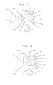
- Fig. 1 an arrangement with a shift rod 1 and a shift fork 2 is shown.
- the shift fork 2 has a circular passage opening 3 in which two spacers 4, 5 are located.
- the shift fork 2 has a blind hole 7 centrally and perpendicular to its central axis 6.
- the shift rod 1 also has a bore 9 perpendicular to its central axis 8.
- the spacers 4, 5 each have a hinged plane surface 4a, 5a.
- the spacers 4, 5 in the middle each have a through hole 4b, 5b.
- the holes 7, 9, 4b, 5b are arranged in alignment. Through the holes 7, 9, 4b, 5b a pin 10 is inserted. This pin 10 forms the pivot axis 11.
- the bore 9 is larger in diameter than the diameter of the pin 10.
- the shift rod 1 has flats 12, 13, which are formed equal deep.
- the length of the flats 12, 13 is also the same.
- the flats 12, 13 are formed symmetrically to the central axis 8 of the shift rod 1.
- the flats 12, 13 are in contact with planar surfaces 4a, 5a.
- On the opposite side of the respective planar surfaces 4a, 5a is in each case a surface 4c, 5c in contact with the passage opening 3 of the shift fork 2.
- a pivoting movement 14 about the pivot axis 11 slide the surfaces 4a, 5a at the flats 12, 13 from.
- the spacers 4, 5 have an identical height.
- Fig. 2 is a cross section from Fig. 1 to see.
- a radial distance which is determined by the spacers 4, 5.
- the curved surface 4c, 5c of the spacers 4, 5 has the same radius as the circular passage opening 3 of the shift fork 2.
- the two spacers 4, 5 are identical in their cross-sectional shape. In this case, both spacers 4, 5 at the transition of the respective surfaces 4a to 4c and 5a to 5c a rounding.
- Fig. 3 shows a cross section through a further shift fork 2.
- This shift fork 2 has a claw-like opening 15 with two opposite plane-parallel surfaces 15 a.
- a shift rod 1 which comprises two spacers 4, 5.
- the two spacers 4, 5 point a rectangular cross section. Height and width of the spacers 4, 5 is identical.
- the spacers 4, 5 contact the flat surfaces 4a, 5a each other.
- the respective opposite planar surfaces 4a, 5a contact the corresponding contact surfaces 15a.
- the shift rod 1 has a passage opening 19 in which the spacers 4, 5 are located.
- the pivot axis 11 is again formed by a pin 10 which penetrates the shift fork 2, the shift rod 1 and the two spacers 4, 5. In a pivoting movement 14, the surfaces 4a, 5a shear off at 15a.
- Fig. 4 shows a similar arrangement as Fig. 3
- the spacers 4, 5 one of Fig. 3 different cross section.
- the spacers 4, 5 each have a planar surface 4a, 5a, which are in contact with the respective surfaces 15a and shear.
- the shift rod 1 has no passage opening for the spacers 4, 5.
- With the shift rod 1 are the curved surfaces 4c, 5c of the spacers 4, 5 in contact.
- the pivoting movement 14 via a pin connection with a pin 10 about the pivot axis eleventh
- Fig. 5 shows a cross section through a compound of a shift fork 2 with a shift rod 1.
- the shift fork 2 in this case has a circular passage opening 3.
- spacers 4, 5 are arranged between shift fork 2 and shift rod 1 spacers 4, 5 are arranged.
- the spacers 4, 5 are arranged doubled here.
- a radial distance between the shift rod 1 and passage opening 3 is ensured.
- the arrangement is penetrated by a pin 10, which has a pivot axis 11.
- the spacers 4, 5 are identical in their cross-section and, opposite their flat surfaces 4a, 5a, have a curved surface 4c, 5c. These curved surfaces are in contact with the shift rod 1 or the through hole 3 of the shift fork 2.
- Fig. 6 shows an arrangement based on Fig. 1 however, the shift rod 1 has a flat 12. On this flat 12, two spacers 4, 5 are arranged serially in one another. These two spacers 4, 5 are identically formed. In this arrangement, the two spacers 4 , 5 mirror images of the central axis 8 on the opposite side have additional identical spacers.
Landscapes
- Engineering & Computer Science (AREA)
- General Engineering & Computer Science (AREA)
- Mechanical Engineering (AREA)
- Gear-Shifting Mechanisms (AREA)
Abstract
Description
- Die Erfindung betrifft eine Schaltvorrichtung mit einer Schaltgabel und einer Schaltstange, die gelenkig miteinander verbunden sind.
- Eine derartige Schaltvorrichtung ist aus
DE 199 40 628 C1 bekannt. Die Schaltvorrichtung weist eine Schaltgabel auf, welche über eine Öffnung auf einer Schaltstange angeordnet ist. Eine Stiftverbindung hält die Schaltgabel relativ zur Schaltstange fest. Die Schaltstange und die Schaltgabel ist im Bereich der Öffnung abgeflacht. Die Schaltgabel und die Schaltstange sind geringfügig verschwenkbar ausgebildet. Die Schaltmuffe unterliegt Taumelbewegungen, welche durch die Schaltgabel an die Schaltstange vermittelt werden. Das Verschwenken gleicht die Taumelbewegungen aus. Aufgrund der individuellen Bauweisen der Schaltgabeln und der Schaltstangen, muss auch jede gelenkige Verbindung individuell ausgeführt sein. Diese Teilevielfalt erhöht den Fertigungsaufwand und die Logistik. Aufgrund der Abflachungen an der Schaltgabel ist es notwendig, die Schaltgabel seitlich zur Schaltstange zuzuführen. Dabei ist ein offener Querschnitt der Öffnung an der Schaltgabel erforderlich, welcher an Stabilität verliert. Die Schaltstange ist durch die Abflachungen lokal geschwächt, was sich nachteilig auf die Stabilität auswirkt. - Aufgabe der Erfindung ist es daher, eine für die Massenfertigung geeignete Schaltvorrichtung zu schaffen, die Taumelbewegungen der Schaltmuffe ausgleicht und hohe Momente aufnehmen kann.
- Erfindungsgemäß wird diese Aufgabe dadurch gelöst, dass eine Schaltvorrichtung nach dem Oberbegriff des Anspruchs 1 mehrere Distanzstücke mit planen Flächen aufweist, die sich an planen Gegenflächen abstützen und gegenüber diesen verschiebbar sind.
- Schaltstangen, darunter sind auch Schaltschienen oder Schaltwellen zu verstehen, werden in Getrieben zur Übertragung von Schalt- oder Wählbewegungen eingesetzt. Auf den Schaltstangen sind die Schaltgabeln verschwenkbeweglich über ein Gelenk in der Öffnung der Schaltgabel angeordnet. Die Gelenkachse bildet ein Stift, welcher die Schaltgabel mit der Schaltstange verbindet. Über die Stiftachse ist eine Verschwenkbewegung möglich, die Taumelbewegungen von der Schaltmuffe zur Schaltstange ausgleicht.
- Erfindungsgemäß werden zwischen der Schaltgabelöffnung und dem Schaltstange mehrere Distanzstücke angeordnet. Zwischen Schaltgabelöffnung und Schaltstange ist ein radialer Zwischenraum, der über diese Distanzstücke lokal überbrückt wird. Die Distanzstücke können dabei auch von der Stiftverbindung durchdrungen sein. Die Distanzstücke besitzen plane Flächen und gewölbte Flächen. Die planen Flächen stehen in Kontakt mit komplementären planen Flächen oder Abflachungen, welche an dem Schaltstange angeordnet sind. Die gewölbten Flächen stehen in formschlüssigen Kontakt mit der Schaltgabelöffnung. Bei einer Verschwenkbewegung der Schaltgabel werden die Distanzstücke über ihre gewölbten Flächen mitgenommen, können jedoch an ihren planen Flächen mit den Abflachungen abscheren. Durch den hohen verbleibenden Flächenkontakt bei einem bestimmten Verschwenkwinkel können höhere Kräfte aufgenommen werden. Somit verstärken die Distanzstücke vorteilhafterweise das Gelenk.
- Weiterhin können auf den Distanzstücken Beschichtungen zur Verschleißminimierung vorgesehen werden. Der Herstellungsaufwand ist bei den einfachen Distanzstücken gering. Vorteilhaft für die Funktion ist hierbei, dass bei geringem Schwenkwinkel viel Kontaktfläche zur Führung der Schwenkbewegung verbleibt.
- Alternativ kann auch auf der Schaltstange eine konkav oder konvex gewölbte Fläche angeordnet sein, die die gewölbten Flächen der Distanzstücke aufnimmt. Dabei sollte die Schaltgabelöffnung die komplementären planen Flächen zu den planen Flächen der Distanzstücke aufweisen.
- Erfindungsgemäß können die Distanzstücke zwei zueinander planparallele Flächen aufweisen. Die Distanzstücke sind mit ihrer einfachen Form von Quadern oder Würfeln leicht herzustellen.
- In einer weiterführenden Ausbildung der Erfindung erstrecken sich die Distanzstücke in Axialrichtung der Schaltstange. Die Schaltgabelöffnung ist entsprechend lang gefasst, um die Distanzstücke einzuhüllen. Durch die verlängerte Abstützung wird das Gelenk in den verbleibenden gesperrten Freiheitsgraden verstärkt ausgebildet, was sich vorteilhaft auf die Lebensdauer auswirkt.
- Alternativ können mehrere kleinere Distanzstücke seriell in Axialrichtung der Schaltstange angeordnet werden, um die Kontaktfläche zu erhöhen. Dabei müssen die Distanzstücke nicht von der Stiftverbindung durchdrungen werden. Dies ist vorteilhaft, um Herstellkosten durch das Ausbilden von Stiftaufnahmelöchern an den Distanzstücken zu sparen.
- In einer weiteren Ausbildung der Erfindung sind die Distanzstücke derart angeordnet, dass der Umfang der Schaltstange zur Aufnahme der Schaltgabel mit der Schaltgabelöffnung vergrößert wird. Das Gelenk weist dabei zwei oder mehrere sich päarchenweise gegenüberliegende Distanzstücke auf. Damit wird die momentenübertragende Fläche im Gelenk vergrößert und kann höheren Belastungen standhalten.
- Ein weiterer Vorteil der Umfangsvergrößerung durch die Distanzstücke ist, dass sich eine weitere Montagemöglichkeit erschließt. Die Distanzstücke können auf den Abflachungen der Schaltstange angeordnet werden, während die Schaltgabel mit ihrer Öffnung, die größer ist als der größte Umfang der Schaltstange, fluchtend entlang der Schaltstange montiert wird.
- Eine weitere vorteilhafte Ausbildung der Erfindung stellt eine symmetrische Anordnung der Distanzstücke auf dem Schaltstange dar. Durch die symmetrische Anordnung unterliegt das Gelenk weitestgehend einer wechselnden Belastung. Somit werden die vorzeichenbehafteten Belastungen im geringen Bauraum optimal aufgenommen. Durch die vorteilhafte symmetrische Ausbildung wird die Lebensdauer erhöht. Alternativ kann bei einer gezielten unsymmetrischen Anordnung der Distanzstücke an dem Schaltstange auf unterschiedliche Belastungshöhen reagiert werden.
- Erfindungsgemäß sind die Distanzstücke identisch ausgebildet. Dadurch ist kein Zupaaren erforderlich, so dass die Montage weiter vereinfacht wird. Ebenfalls wird ein Sortieren für die Montage vermieden und der Aufwand reduziert.
- Vorteilhafterweise können für die Distanzstücke verschiedenste Materialien oder lebensdauerverlängernde Beschichtungen ausgebildet werden. Dies vermeidet eine teure Anordnung verschleißfester Materialien an Schaltgabel oder Schaltstange sowie eine komplette Ausbildung der Schaltgabel oder Schaltstange durch solche Werkstoffe.
- In einer vorteilhaften Ausgestaltung der Erfindung sind die Abflachungen an der Schaltstange parallel ausgebildet. Die Distanzstücke weisen hierbei in Längsrichtung einen konstanten Querschnitt auf. Diese planparallele Ausbildung vereinfacht die Montage der Distanzstücke an der Schaltstange.
- Alternativ können die Abflachungen auf der Schaltstange nicht planparallel ausgebildet sein. Dabei erstrecken sich die Flächen in Längsachse der Schaltstange konisch aufeinander zu oder voneinander weg. Die planen Flächen an den Distanzstücken sind ebenfalls konisch ausgebildet und verjüngen oder verbreitern den Querschnitt. In dieser Ausbildung können Toleranzanforderungen an die Flächen grob angegeben werden. Eine Parallelisierung der Mittelachsen von Schaltgabelöffnung und Schaltstange kann durch Zupaaren der Distanzstücke zum jeweiligen Ist-Stand stattfinden. Alternativ können auch Abflachungen an der Schaltgabel die Schaltgabelöffnung verjüngen oder verbreitern.
- Die konische Ausbildung in Längsrichtung ist unter Belastung vorteilhaft, dass bei Krafteinleitung in Längsrichtung der Schaltstange die Distanzstücke keilig verspannend mit der Schaltgabelöffnung wirken. Die Distanzstücke unterstützen die Aufnahme axialer Kräfte im Gelenk. Bei einem Einrasten der Schaltstange in ein Rastelement erfolgt ein geringer Rückweg, der die Keilverbindung wieder entlastet, damit das Gelenk die Taumelbewegung der im Eingriff befindlichen Schaltmuffe ausgleichen kann.
- Eine weitere vorteilhafte Ausbildung der Erfindung stellt eine Koaxialität der Mittelachse der Schaltgabelöffnung und der Mittelachse der Schaltstange dar. Durch die Distanzstücke und deren Höhen können die Mittelachsen vorteilhafterweise fluchtend ausgebildet werden. Dies kann durch eine Zusortierung der entsprechenden Distanzstücke mit deren verschiedenen Höhen erfolgen. Sofern keine Mittelachse aufgrund eines nicht vorhandenen kreisförmigen Querschnittes definiert werden kann, können über die Distanzstücke die radialen Abstände zwischen der Schaltgabelöffnung und der Schaltstange eingestellt werden. Eine weitestgehend symmetrische Anordnung hat Vorteile bei der Minimierung möglicher Kippmomente durch die axiale Bewegung der Schaltstange auf die Schaltgabel.
- Die Erfindung sieht eine weitere vorteilhafte Ausgestaltung derart vor, dass ein Radius am Umfang des Distanzstückes gleich dem Radius in der Aufnahme der Schaltgabelöffnung ist. Bei einer Verdrehbewegung der Schaltgabel um die Längsachse der Schaltstange können dadurch Kräfte über eine größtmögliche Fläche zwischen der Schaltgabel und dem Distanzstück übertragen werden. Durch die Schmiegung wird die Stiftverbindung entlastet.
- In einer Ausgestaltung der Erfindung ist die Schaltgabelöffnung umfangsseitig geschlossen ausgebildet. Für eine Leichtbauweise kann die Schaltgabelöffnung alternativ an diskreten Stellen umfangsseitig geschlossen sein. Durchbrüche, die einen Teil des Gelenkes freilegen sind vorteilhaft für die Zugängigkeit der Schmierung des Gelenkes, was die Lebensdauer erhöht. Eine vollständig über die gesamte Länge hinweg umfangsseitig geschlossene Schaltgabelöffnung stellt die maximale Stabilität zur Verfügung.
- Durch die erfindungsgemäßen Ausgestaltungen der Distanzstücke und deren Anordnung mit der Verbindung zwischen Schaltgabelöffnung und Schaltstange lässt sich ein Verschwenkgelenk in der Massenfertigung herstellen.
- Kurze Beschreibung der Zeichnungen Ausführungsbeispiele der Erfindung sind in den Figuren dargestellt.
-
- Fig. 1
- einen Längsschnitt durch eine Anordnung mit einer Schaltstange und balligen Distanzstücken,
- Fig. 2
- einen Querschnitt durch die Anordnung nach
Fig. 1 , - Fig. 3
- einen Querschnitt durch eine weitere Anordnung mit einer Schaltschiene und quaderförmigen Distanzstücken,
- Fig. 4
- einen Querschnitt durch eine weitere Anordnungsform mit einer Schaltschiene und gewölbten Distanzstücken,
- Fig. 5
- einen Querschnitt durch eine weitere Anordnung mit einer Schaltstange und mehreren miteinander verbundenen konvexen Distanzstücken und
- Fig. 6
- einen Längsschnitt durch eine weitere Anordnung mit einer Schaltstange und mehreren seriell angeordneten Distanzstücken.
- In
Fig. 1 ist eine Anordnung mit einer Schaltstange 1 und einer Schaltgabel 2 dargestellt. Die Schaltgabel 2 hat eine kreisförmige Durchgangsöffnung 3 in denen sich zwei Distanzstücke 4, 5 befinden. Die Schaltgabel 2 weist mittig und senkrecht zu ihrer Mittelachse 6 eine Sacklochbohrung 7 auf. Die Schaltstange 1 weist ebenfalls senkrecht zu ihrer Mittelachse 8 eine Bohrung 9 auf. Die Distanzstücke 4, 5 weisen jeweils eine gelenkig wirkende plane Fläche 4a, 5a auf. Weiterhin weisen die Distanzstücke 4, 5 mittig jeweils eine Durchgangsbohrung 4b, 5b auf. Die Bohrungen 7, 9, 4b, 5b sind fluchtend angeordnet. Durch die Bohrungen 7, 9, 4b, 5b ist ein Stift 10 durchgesteckt. Dieser Stift 10 bildet die Verschwenkachse 11. Die Bohrung 9 ist in ihrem Durchmesser größer als der Durchmesser des Stifts 10. Die Schaltstange 1 weist Abflachungen 12, 13 auf, die gleich tief ausgebildet sind. Die Länge der Abflachungen 12, 13 ist ebenfalls gleich. Die Abflachungen 12, 13 sind symmetrisch zur Mittelachse 8 der Schaltstange 1 ausgebildet. Die Abflachungen 12, 13 stehen in Kontakt mit planen Flächen 4a, 5a. Auf der Gegenseite der jeweiligen planen Flächen 4a, 5a ist jeweils eine Fläche 4c, 5c in Kontakt mit der Durchgangsöffnung 3 der Schaltgabel 2. Bei einer Verschwenkbewegung 14 um die Verschwenkachse 11 gleiten die Flächen 4a, 5a an den Abflachungen 12, 13 ab. Die Distanzstücke 4, 5 weisen eine identische Höhe auf. - In
Fig. 2 ist ein Querschnitt ausFig. 1 zu sehen. Zwischen der Schaltgabel 2 und der Schaltstange 1 ist ein radialer Abstand, der von den Distanzstücken 4, 5 bestimmt wird. Dabei hat die gewölbte Fläche 4c, 5c der Distanzstücke 4, 5 den gleichen Radius, wie die kreisförmige Durchgangsöffnung 3 der Schaltgabel 2. Die beiden Distanzstücke 4, 5 sind in ihrer Querschnittsform identisch. Dabei weisen beide Distanzstücke 4, 5 am Übergang der jeweiligen Flächen 4a zu 4c bzw. 5a zu 5c eine Abrundung auf. -
Fig. 3 zeigt einen Querschnitt durch eine weitere Schaltgabel 2. Diese Schaltgabel 2 hat eine klauenartige Öffnung 15 mit zwei gegenüberliegenden planparallelen Flächen 15a. In der Öffnung 15 befindet sich eine Schaltstange 1, welche zwei Distanzstücke 4, 5 umfasst. Die beiden Distanzstücke 4, 5 weisen einen rechteckigen Querschnitt auf. Höhe und Breite der Distanzstücke 4, 5 ist identisch. Dabei kontaktieren die Distanzstücke 4, 5 mit den planen Flächen 4a, 5a einander. Die jeweiligen gegenüberliegenden planen Flächen 4a, 5a kontaktieren die entsprechenden Anlageflächen 15a. Die Schaltstange 1 weist eine Durchgangsöffnung 19 auf, in der sich die Distanzstücke 4, 5 befinden. Die Verschwenkachse 11 wird wiederum durch einen Stift 10 gebildet, welche die Schaltgabel 2, die Schaltstange 1 und die beiden Distanzstücken 4, 5 durchdringt. Bei einer Verschwenkbewegung 14 scheren die Flächen 4a, 5a mit 15a ab. -
Fig. 4 zeigt eine ähnliche Anordnung wieFig. 3 , jedoch weisen die Distanzstücke 4, 5 einen vonFig. 3 verschiedenen Querschnitt auf. Die Distanzstücke 4, 5 haben jeweils eine plane Fläche 4a, 5a, welche mit den jeweiligen Flächen 15a in Kontakt stehen und abscheren. In dieser Anordnung weist die Schaltstange 1 keine Durchgangsöffnung für die Distanzstücke 4, 5 auf. Mit der Schaltstange 1 stehen die gewölbten Flächen 4c, 5c der Distanzstücke 4, 5 in Kontakt. Die Verschwenkbewegung 14 erfolgt über eine Stiftverbindung mit einem Stift 10 um die Verschwenkachse 11. -
Fig. 5 zeigt einen Querschnitt durch eine Verbindung einer Schaltgabel 2 mit einer Schaltstange 1. Die Schaltgabel 2 weist hierbei eine kreisrunde Durchgangsöffnung 3 auf. Zwischen Schaltgabel 2 und Schaltstange 1 sind Distanzstücke 4, 5 angeordnet. Die Distanzstücke 4, 5 sind hier gedoppelt angeordnet. Über diese Distanzstücke 4, 5 ist ein radialer Abstand zwischen Schaltstange 1 und Durchgangsöffnung 3 gewährleistet. Die Anordnung wird von einem Stift 10 durchdrungen, welcher eine Verschwenkachse 11 aufweist. Bei einer Verschwenkbewegung 14 um die Verschwenkachse 11 scheren die planen Flächen 4a mit 5a der Distanzstücke 4, 5 aufeinander ab. Die Distanzstücke 4, 5, sind identisch in ihrem Querschnitt und weisen gegenüberliegend ihrer planen Flächen 4a, 5a eine gewölbte Fläche 4c, 5c auf. Diese gewölbten Flächen stehen mit der Schaltstange 1 oder der Durchgangsöffnung 3 der Schaltgabel 2 in Kontakt. -
Fig. 6 zeigt eine Anordnung basierend aufFig. 1 wobei jedoch die Schaltstange 1 eine Abflachung 12 aufweist. Auf dieser Abflachung 12 sind zwei Distanzstücke 4, 5 seriell ineinander angeordnet. Diese beiden Distanzstücke 4, 5 sind identisch ausgebildet. In dieser Anordnung können auch die beiden Distanzstücke 4, 5 spiegelbildlich zur Mittelachse 8 auf der Gegenseite zusätzliche identische Distanzstücke aufweisen. -
- 1)
- Schaltstange
- 2)
- Schaltgabel
- 3)
- Durchgangsöffnung
- 4)
- Distanzstück
- 4a)
- plane Fläche
- 4b)
- Durchgangsbohrung
- 4c)
- gewölbte Fläche
- 5)
- Distanzstück
- 5a)
- plane Fläche
- 5b)
- Durchgangsbohrung
- 5c)
- gewölbte Fläche
- 6)
- Mittelachse (Schaltgabel)
- 7)
- Sacklochbohrung
- 8)
- Mittelachse (Schaltstange)
- 9)
- Durchgangsöffnung 10) Stift 11)Verschwenkachse 12)Abflachung 13)Abflachung 14)Verschwenkbewegung 15)klauenartige Öffnung
- 15a)
- planparallele Fläche
Claims (11)
- Schaltvorrichtung mit einer Schaltstange (1) und einer Schaltgabel (2), wobei die Schaltstange (1) in einer Öffnung (3) der Schaltgabel (2) angeordnet ist und zwischen der Schaltstange (1) und der Schaltgabel (2) ein Zwischenraum verbleibt, dadurch gekennzeichnet, dass in dem Zwischenraum mehrere Distanzstücke (4, 5) angeordnet sind, die gelenkig wirkende plane Flächen (4a, 5a) zur Ausbildung eines Flächenkontaktes aufweisen.
- Schaltvorrichtung nach Anspruch 1, dadurch gekennzeichnet, dass die Schaltstange (1) gelenkig wirkende Abflachungen (12, 13) aufweist.
- Schaltvorrichtung nach Anspruch 1, dadurch gekennzeichnet, dass die Distanzstücke (4, 5) in Längsrichtung der Schaltstange (1) die größte Dimension aufweisen.
- Schaltvorrichtung nach Anspruch 1, dadurch gekennzeichnet, dass die Distanzstücke (4, 5) den Umfang der Schaltstange (1) vergrößern.
- Schaltvorrichtung nach Anspruch 1, dadurch gekennzeichnet, dass die Schaltgabel (2) eine umfangsseitig vollständig geschlossene Öffnung (3) aufweist.
- Schaltvorrichtung nach Anspruch 1, dadurch gekennzeichnet, dass die Schaltstange (1), die Schaltgabel (2) und Distanzstücke (4, 5) von einem Stift durchdrungen sind.
- Schaltvorrichtung nach Anspruch 1, dadurch gekennzeichnet, dass die Distanzstücke (4, 5) symmetrisch auf der Schaltstange (1) angeordnet sind.
- Schaltvorrichtung nach Anspruch 1, dadurch gekennzeichnet, dass die Distanzstücke (4, 5) identisch sind.
- Schaltvorrichtung nach Anspruch 1, dadurch gekennzeichnet, dass die planen Flächen (4a, 5a) der Distanzstücke (4, 5) planparallel zueinander sind.
- Schaltvorrichtung nach Anspruch 1, dadurch gekennzeichnet, dass die Schaltgabel (2) axialbeweglich auf der Schaltstange (1) angeordnet ist.
- Schaltvorrichtung nach Anspruch 1, dadurch gekennzeichnet, dass zur Maximierung der Kontaktfläche zwischen der Schaltgabel (2) und den Distanzstücken (4, 5) eine Krümmung einer gewölbten Fläche (4c, 5c) des Distanzstückes (4, 5)) und eine Krümmung der Öffnung (3) gleich groß ist.
Applications Claiming Priority (1)
| Application Number | Priority Date | Filing Date | Title |
|---|---|---|---|
| DE201010045873 DE102010045873A1 (de) | 2010-09-17 | 2010-09-17 | Anordnung einer Schaltstange mit einer Schaltgabel |
Publications (2)
| Publication Number | Publication Date |
|---|---|
| EP2431637A1 true EP2431637A1 (de) | 2012-03-21 |
| EP2431637B1 EP2431637B1 (de) | 2012-12-05 |
Family
ID=44681521
Family Applications (1)
| Application Number | Title | Priority Date | Filing Date |
|---|---|---|---|
| EP20110168152 Not-in-force EP2431637B1 (de) | 2010-09-17 | 2011-05-31 | Anordnung einer Schaltstange mit einer Schaltgabel |
Country Status (2)
| Country | Link |
|---|---|
| EP (1) | EP2431637B1 (de) |
| DE (1) | DE102010045873A1 (de) |
Citations (3)
| Publication number | Priority date | Publication date | Assignee | Title |
|---|---|---|---|---|
| DE19940628C1 (de) | 1999-08-27 | 2001-03-08 | Selzer Fertigungstech | Schaltschiene mit daran befestigter Schaltgabel für Kraftfahrzeug-Schaltgetriebe |
| DE10159441A1 (de) * | 2001-12-04 | 2003-06-18 | Ina Schaeffler Kg | Schaltgabel an einer relativ zu einem Wechselgetriebe verschiebbaren Schaltschiene |
| DE10236594A1 (de) * | 2002-08-09 | 2004-02-26 | Audi Ag | Schaltvorrichtung |
-
2010
- 2010-09-17 DE DE201010045873 patent/DE102010045873A1/de not_active Withdrawn
-
2011
- 2011-05-31 EP EP20110168152 patent/EP2431637B1/de not_active Not-in-force
Patent Citations (3)
| Publication number | Priority date | Publication date | Assignee | Title |
|---|---|---|---|---|
| DE19940628C1 (de) | 1999-08-27 | 2001-03-08 | Selzer Fertigungstech | Schaltschiene mit daran befestigter Schaltgabel für Kraftfahrzeug-Schaltgetriebe |
| DE10159441A1 (de) * | 2001-12-04 | 2003-06-18 | Ina Schaeffler Kg | Schaltgabel an einer relativ zu einem Wechselgetriebe verschiebbaren Schaltschiene |
| DE10236594A1 (de) * | 2002-08-09 | 2004-02-26 | Audi Ag | Schaltvorrichtung |
Also Published As
| Publication number | Publication date |
|---|---|
| DE102010045873A1 (de) | 2012-03-22 |
| EP2431637B1 (de) | 2012-12-05 |
Similar Documents
| Publication | Publication Date | Title |
|---|---|---|
| EP2994625B1 (de) | Nockenwelle | |
| DE69722198T2 (de) | Kettentrieb und kette dafür | |
| EP3752694B1 (de) | Autoparkvorrichtung | |
| DE102009045275B4 (de) | Schwenkmodul für eine Anhängerkupplung | |
| EP2875533B1 (de) | Aktuatorvorrichtung mit magnetischem formgedächtniselement | |
| EP1876363B1 (de) | Verstellvorrichtung für eine Bowdenzuganordnung | |
| DE102011013357A1 (de) | Leistungsfähige miniaturisierte Schubkette mit einer reduzierten Drucklaschenhöhe aufgrund des Einsatzes von Drucklaschen mit multifunktionalen Drehgelenken | |
| EP2431637B1 (de) | Anordnung einer Schaltstange mit einer Schaltgabel | |
| DE102004007045B3 (de) | Beschlag für einen Fahrzeugsitz | |
| EP2201257A1 (de) | Elastische wellenkupplung | |
| EP1019642A1 (de) | Gelenkanordnung zur übertragung von drehmomentgeeigneten gelenkwellen | |
| EP2581614A2 (de) | Kugelschwenkmodul | |
| DE102008049348A1 (de) | Kreuzgelenkanordnung für eine Gelenkwelle | |
| WO2007121957A1 (de) | Förderkette | |
| EP3789186A1 (de) | Ultraschallbearbeitungsvorrichtung | |
| DE102013202764B4 (de) | Koppelstange | |
| EP3042104B1 (de) | Stufenloses getriebe | |
| DE2302457C3 (de) | Kettenschloß | |
| EP4112416B1 (de) | Kupplungsvorrichtung mit einstückigen federpaketen | |
| EP3832154B1 (de) | Kugelgelenklager und kugelgelenkanordnung mit einem kugelgelenklager | |
| DE102005058743A1 (de) | Kreuzgelenkanordnung | |
| WO2025131608A1 (de) | Mehrteilige wellenvorrichtung eines triebstrangs einer aufzuganlage sowie entsprechend ausgestatteter triebstrang und verwendung | |
| WO2007009811A2 (de) | Hydrostatische kolbenmaschine nach floating-cup-prinzip mit anlagefläche an trägerplatte | |
| EP1466082A1 (de) | Schaltbarer nockenfolger oder schaltbares abstützelement eines ventiltriebs einer brennkraftmaschine | |
| EP1518623B1 (de) | Vorrichtung zum Verbinden eines Werkzeugteils mit einem Aufnahmeteil |
Legal Events
| Date | Code | Title | Description |
|---|---|---|---|
| PUAI | Public reference made under article 153(3) epc to a published international application that has entered the european phase |
Free format text: ORIGINAL CODE: 0009012 |
|
| 17P | Request for examination filed |
Effective date: 20110531 |
|
| AK | Designated contracting states |
Kind code of ref document: A1 Designated state(s): AL AT BE BG CH CY CZ DE DK EE ES FI FR GB GR HR HU IE IS IT LI LT LU LV MC MK MT NL NO PL PT RO RS SE SI SK SM TR |
|
| AX | Request for extension of the european patent |
Extension state: BA ME |
|
| 17Q | First examination report despatched |
Effective date: 20111028 |
|
| GRAP | Despatch of communication of intention to grant a patent |
Free format text: ORIGINAL CODE: EPIDOSNIGR1 |
|
| RIC1 | Information provided on ipc code assigned before grant |
Ipc: F16H 63/32 20060101AFI20120509BHEP |
|
| GRAS | Grant fee paid |
Free format text: ORIGINAL CODE: EPIDOSNIGR3 |
|
| GRAA | (expected) grant |
Free format text: ORIGINAL CODE: 0009210 |
|
| AK | Designated contracting states |
Kind code of ref document: B1 Designated state(s): AL AT BE BG CH CY CZ DE DK EE ES FI FR GB GR HR HU IE IS IT LI LT LU LV MC MK MT NL NO PL PT RO RS SE SI SK SM TR |
|
| REG | Reference to a national code |
Ref country code: GB Ref legal event code: FG4D Free format text: NOT ENGLISH |
|
| REG | Reference to a national code |
Ref country code: CH Ref legal event code: EP |
|
| REG | Reference to a national code |
Ref country code: AT Ref legal event code: REF Ref document number: 587465 Country of ref document: AT Kind code of ref document: T Effective date: 20121215 |
|
| REG | Reference to a national code |
Ref country code: IE Ref legal event code: FG4D Free format text: LANGUAGE OF EP DOCUMENT: GERMAN |
|
| REG | Reference to a national code |
Ref country code: DE Ref legal event code: R096 Ref document number: 502011000255 Country of ref document: DE Effective date: 20130131 |
|
| PG25 | Lapsed in a contracting state [announced via postgrant information from national office to epo] |
Ref country code: LT Free format text: LAPSE BECAUSE OF FAILURE TO SUBMIT A TRANSLATION OF THE DESCRIPTION OR TO PAY THE FEE WITHIN THE PRESCRIBED TIME-LIMIT Effective date: 20121205 Ref country code: ES Free format text: LAPSE BECAUSE OF FAILURE TO SUBMIT A TRANSLATION OF THE DESCRIPTION OR TO PAY THE FEE WITHIN THE PRESCRIBED TIME-LIMIT Effective date: 20130316 Ref country code: SE Free format text: LAPSE BECAUSE OF FAILURE TO SUBMIT A TRANSLATION OF THE DESCRIPTION OR TO PAY THE FEE WITHIN THE PRESCRIBED TIME-LIMIT Effective date: 20121205 Ref country code: HR Free format text: LAPSE BECAUSE OF FAILURE TO SUBMIT A TRANSLATION OF THE DESCRIPTION OR TO PAY THE FEE WITHIN THE PRESCRIBED TIME-LIMIT Effective date: 20121205 Ref country code: FI Free format text: LAPSE BECAUSE OF FAILURE TO SUBMIT A TRANSLATION OF THE DESCRIPTION OR TO PAY THE FEE WITHIN THE PRESCRIBED TIME-LIMIT Effective date: 20121205 Ref country code: NO Free format text: LAPSE BECAUSE OF FAILURE TO SUBMIT A TRANSLATION OF THE DESCRIPTION OR TO PAY THE FEE WITHIN THE PRESCRIBED TIME-LIMIT Effective date: 20130305 |
|
| REG | Reference to a national code |
Ref country code: NL Ref legal event code: VDEP Effective date: 20121205 |
|
| REG | Reference to a national code |
Ref country code: LT Ref legal event code: MG4D |
|
| PG25 | Lapsed in a contracting state [announced via postgrant information from national office to epo] |
Ref country code: LV Free format text: LAPSE BECAUSE OF FAILURE TO SUBMIT A TRANSLATION OF THE DESCRIPTION OR TO PAY THE FEE WITHIN THE PRESCRIBED TIME-LIMIT Effective date: 20121205 Ref country code: GR Free format text: LAPSE BECAUSE OF FAILURE TO SUBMIT A TRANSLATION OF THE DESCRIPTION OR TO PAY THE FEE WITHIN THE PRESCRIBED TIME-LIMIT Effective date: 20130306 Ref country code: SI Free format text: LAPSE BECAUSE OF FAILURE TO SUBMIT A TRANSLATION OF THE DESCRIPTION OR TO PAY THE FEE WITHIN THE PRESCRIBED TIME-LIMIT Effective date: 20121205 Ref country code: PL Free format text: LAPSE BECAUSE OF FAILURE TO SUBMIT A TRANSLATION OF THE DESCRIPTION OR TO PAY THE FEE WITHIN THE PRESCRIBED TIME-LIMIT Effective date: 20121205 |
|
| PG25 | Lapsed in a contracting state [announced via postgrant information from national office to epo] |
Ref country code: SK Free format text: LAPSE BECAUSE OF FAILURE TO SUBMIT A TRANSLATION OF THE DESCRIPTION OR TO PAY THE FEE WITHIN THE PRESCRIBED TIME-LIMIT Effective date: 20121205 Ref country code: EE Free format text: LAPSE BECAUSE OF FAILURE TO SUBMIT A TRANSLATION OF THE DESCRIPTION OR TO PAY THE FEE WITHIN THE PRESCRIBED TIME-LIMIT Effective date: 20121205 Ref country code: RS Free format text: LAPSE BECAUSE OF FAILURE TO SUBMIT A TRANSLATION OF THE DESCRIPTION OR TO PAY THE FEE WITHIN THE PRESCRIBED TIME-LIMIT Effective date: 20121205 Ref country code: IS Free format text: LAPSE BECAUSE OF FAILURE TO SUBMIT A TRANSLATION OF THE DESCRIPTION OR TO PAY THE FEE WITHIN THE PRESCRIBED TIME-LIMIT Effective date: 20130405 Ref country code: CZ Free format text: LAPSE BECAUSE OF FAILURE TO SUBMIT A TRANSLATION OF THE DESCRIPTION OR TO PAY THE FEE WITHIN THE PRESCRIBED TIME-LIMIT Effective date: 20121205 Ref country code: BG Free format text: LAPSE BECAUSE OF FAILURE TO SUBMIT A TRANSLATION OF THE DESCRIPTION OR TO PAY THE FEE WITHIN THE PRESCRIBED TIME-LIMIT Effective date: 20130305 |
|
| PG25 | Lapsed in a contracting state [announced via postgrant information from national office to epo] |
Ref country code: NL Free format text: LAPSE BECAUSE OF FAILURE TO SUBMIT A TRANSLATION OF THE DESCRIPTION OR TO PAY THE FEE WITHIN THE PRESCRIBED TIME-LIMIT Effective date: 20121205 Ref country code: RO Free format text: LAPSE BECAUSE OF FAILURE TO SUBMIT A TRANSLATION OF THE DESCRIPTION OR TO PAY THE FEE WITHIN THE PRESCRIBED TIME-LIMIT Effective date: 20121205 Ref country code: PT Free format text: LAPSE BECAUSE OF FAILURE TO SUBMIT A TRANSLATION OF THE DESCRIPTION OR TO PAY THE FEE WITHIN THE PRESCRIBED TIME-LIMIT Effective date: 20130405 |
|
| PLBE | No opposition filed within time limit |
Free format text: ORIGINAL CODE: 0009261 |
|
| STAA | Information on the status of an ep patent application or granted ep patent |
Free format text: STATUS: NO OPPOSITION FILED WITHIN TIME LIMIT |
|
| PG25 | Lapsed in a contracting state [announced via postgrant information from national office to epo] |
Ref country code: DK Free format text: LAPSE BECAUSE OF FAILURE TO SUBMIT A TRANSLATION OF THE DESCRIPTION OR TO PAY THE FEE WITHIN THE PRESCRIBED TIME-LIMIT Effective date: 20121205 |
|
| 26N | No opposition filed |
Effective date: 20130906 |
|
| PG25 | Lapsed in a contracting state [announced via postgrant information from national office to epo] |
Ref country code: CY Free format text: LAPSE BECAUSE OF FAILURE TO SUBMIT A TRANSLATION OF THE DESCRIPTION OR TO PAY THE FEE WITHIN THE PRESCRIBED TIME-LIMIT Effective date: 20121205 |
|
| BERE | Be: lapsed |
Owner name: SCHAEFFLER TECHNOLOGIES A.G. & CO. KG Effective date: 20130531 |
|
| PG25 | Lapsed in a contracting state [announced via postgrant information from national office to epo] |
Ref country code: MC Free format text: LAPSE BECAUSE OF FAILURE TO SUBMIT A TRANSLATION OF THE DESCRIPTION OR TO PAY THE FEE WITHIN THE PRESCRIBED TIME-LIMIT Effective date: 20121205 Ref country code: IT Free format text: LAPSE BECAUSE OF FAILURE TO SUBMIT A TRANSLATION OF THE DESCRIPTION OR TO PAY THE FEE WITHIN THE PRESCRIBED TIME-LIMIT Effective date: 20121205 |
|
| REG | Reference to a national code |
Ref country code: DE Ref legal event code: R097 Ref document number: 502011000255 Country of ref document: DE Effective date: 20130906 |
|
| REG | Reference to a national code |
Ref country code: IE Ref legal event code: MM4A |
|
| PG25 | Lapsed in a contracting state [announced via postgrant information from national office to epo] |
Ref country code: BE Free format text: LAPSE BECAUSE OF NON-PAYMENT OF DUE FEES Effective date: 20130531 |
|
| REG | Reference to a national code |
Ref country code: FR Ref legal event code: ST Effective date: 20140131 |
|
| REG | Reference to a national code |
Ref country code: DE Ref legal event code: R081 Ref document number: 502011000255 Country of ref document: DE Owner name: SCHAEFFLER TECHNOLOGIES AG & CO. KG, DE Free format text: FORMER OWNER: SCHAEFFLER TECHNOLOGIES AG & CO. KG, 91074 HERZOGENAURACH, DE Effective date: 20140218 Ref country code: DE Ref legal event code: R081 Ref document number: 502011000255 Country of ref document: DE Owner name: SCHAEFFLER TECHNOLOGIES GMBH & CO. KG, DE Free format text: FORMER OWNER: SCHAEFFLER TECHNOLOGIES AG & CO. KG, 91074 HERZOGENAURACH, DE Effective date: 20140218 |
|
| PG25 | Lapsed in a contracting state [announced via postgrant information from national office to epo] |
Ref country code: IE Free format text: LAPSE BECAUSE OF NON-PAYMENT OF DUE FEES Effective date: 20130531 |
|
| PG25 | Lapsed in a contracting state [announced via postgrant information from national office to epo] |
Ref country code: FR Free format text: LAPSE BECAUSE OF NON-PAYMENT OF DUE FEES Effective date: 20130531 |
|
| REG | Reference to a national code |
Ref country code: CH Ref legal event code: PL |
|
| PG25 | Lapsed in a contracting state [announced via postgrant information from national office to epo] |
Ref country code: CH Free format text: LAPSE BECAUSE OF NON-PAYMENT OF DUE FEES Effective date: 20140531 Ref country code: LI Free format text: LAPSE BECAUSE OF NON-PAYMENT OF DUE FEES Effective date: 20140531 |
|
| PG25 | Lapsed in a contracting state [announced via postgrant information from national office to epo] |
Ref country code: MT Free format text: LAPSE BECAUSE OF FAILURE TO SUBMIT A TRANSLATION OF THE DESCRIPTION OR TO PAY THE FEE WITHIN THE PRESCRIBED TIME-LIMIT Effective date: 20121205 |
|
| REG | Reference to a national code |
Ref country code: DE Ref legal event code: R081 Ref document number: 502011000255 Country of ref document: DE Owner name: SCHAEFFLER TECHNOLOGIES AG & CO. KG, DE Free format text: FORMER OWNER: SCHAEFFLER TECHNOLOGIES GMBH & CO. KG, 91074 HERZOGENAURACH, DE Effective date: 20150407 |
|
| PG25 | Lapsed in a contracting state [announced via postgrant information from national office to epo] |
Ref country code: SM Free format text: LAPSE BECAUSE OF FAILURE TO SUBMIT A TRANSLATION OF THE DESCRIPTION OR TO PAY THE FEE WITHIN THE PRESCRIBED TIME-LIMIT Effective date: 20121205 |
|
| PG25 | Lapsed in a contracting state [announced via postgrant information from national office to epo] |
Ref country code: TR Free format text: LAPSE BECAUSE OF FAILURE TO SUBMIT A TRANSLATION OF THE DESCRIPTION OR TO PAY THE FEE WITHIN THE PRESCRIBED TIME-LIMIT Effective date: 20121205 |
|
| PG25 | Lapsed in a contracting state [announced via postgrant information from national office to epo] |
Ref country code: HU Free format text: LAPSE BECAUSE OF FAILURE TO SUBMIT A TRANSLATION OF THE DESCRIPTION OR TO PAY THE FEE WITHIN THE PRESCRIBED TIME-LIMIT; INVALID AB INITIO Effective date: 20110531 Ref country code: MK Free format text: LAPSE BECAUSE OF FAILURE TO SUBMIT A TRANSLATION OF THE DESCRIPTION OR TO PAY THE FEE WITHIN THE PRESCRIBED TIME-LIMIT Effective date: 20121205 Ref country code: LU Free format text: LAPSE BECAUSE OF NON-PAYMENT OF DUE FEES Effective date: 20130531 |
|
| GBPC | Gb: european patent ceased through non-payment of renewal fee |
Effective date: 20150531 |
|
| PG25 | Lapsed in a contracting state [announced via postgrant information from national office to epo] |
Ref country code: GB Free format text: LAPSE BECAUSE OF NON-PAYMENT OF DUE FEES Effective date: 20150531 |
|
| REG | Reference to a national code |
Ref country code: AT Ref legal event code: MM01 Ref document number: 587465 Country of ref document: AT Kind code of ref document: T Effective date: 20160531 |
|
| PG25 | Lapsed in a contracting state [announced via postgrant information from national office to epo] |
Ref country code: AT Free format text: LAPSE BECAUSE OF NON-PAYMENT OF DUE FEES Effective date: 20160531 |
|
| PG25 | Lapsed in a contracting state [announced via postgrant information from national office to epo] |
Ref country code: AL Free format text: LAPSE BECAUSE OF FAILURE TO SUBMIT A TRANSLATION OF THE DESCRIPTION OR TO PAY THE FEE WITHIN THE PRESCRIBED TIME-LIMIT Effective date: 20121205 |
|
| PGFP | Annual fee paid to national office [announced via postgrant information from national office to epo] |
Ref country code: DE Payment date: 20210721 Year of fee payment: 11 |
|
| REG | Reference to a national code |
Ref country code: DE Ref legal event code: R119 Ref document number: 502011000255 Country of ref document: DE |
|
| PG25 | Lapsed in a contracting state [announced via postgrant information from national office to epo] |
Ref country code: DE Free format text: LAPSE BECAUSE OF NON-PAYMENT OF DUE FEES Effective date: 20221201 |
|
| P01 | Opt-out of the competence of the unified patent court (upc) registered |
Effective date: 20230522 |