EP2431229A1 - Item holder - Google Patents
Item holder Download PDFInfo
- Publication number
- EP2431229A1 EP2431229A1 EP10774835A EP10774835A EP2431229A1 EP 2431229 A1 EP2431229 A1 EP 2431229A1 EP 10774835 A EP10774835 A EP 10774835A EP 10774835 A EP10774835 A EP 10774835A EP 2431229 A1 EP2431229 A1 EP 2431229A1
- Authority
- EP
- European Patent Office
- Prior art keywords
- gear
- article
- holding device
- pinion
- housing
- Prior art date
- Legal status (The legal status is an assumption and is not a legal conclusion. Google has not performed a legal analysis and makes no representation as to the accuracy of the status listed.)
- Withdrawn
Links
Images


Classifications
-
- B—PERFORMING OPERATIONS; TRANSPORTING
- B60—VEHICLES IN GENERAL
- B60R—VEHICLES, VEHICLE FITTINGS, OR VEHICLE PARTS, NOT OTHERWISE PROVIDED FOR
- B60R11/00—Arrangements for holding or mounting articles, not otherwise provided for
- B60R11/02—Arrangements for holding or mounting articles, not otherwise provided for for radio sets, television sets, telephones, or the like; Arrangement of controls thereof
-
- F—MECHANICAL ENGINEERING; LIGHTING; HEATING; WEAPONS; BLASTING
- F16—ENGINEERING ELEMENTS AND UNITS; GENERAL MEASURES FOR PRODUCING AND MAINTAINING EFFECTIVE FUNCTIONING OF MACHINES OR INSTALLATIONS; THERMAL INSULATION IN GENERAL
- F16M—FRAMES, CASINGS OR BEDS OF ENGINES, MACHINES OR APPARATUS, NOT SPECIFIC TO ENGINES, MACHINES OR APPARATUS PROVIDED FOR ELSEWHERE; STANDS; SUPPORTS
- F16M11/00—Stands or trestles as supports for apparatus or articles placed thereon ; Stands for scientific apparatus such as gravitational force meters
- F16M11/02—Heads
- F16M11/04—Means for attachment of apparatus; Means allowing adjustment of the apparatus relatively to the stand
- F16M11/041—Allowing quick release of the apparatus
-
- F—MECHANICAL ENGINEERING; LIGHTING; HEATING; WEAPONS; BLASTING
- F16—ENGINEERING ELEMENTS AND UNITS; GENERAL MEASURES FOR PRODUCING AND MAINTAINING EFFECTIVE FUNCTIONING OF MACHINES OR INSTALLATIONS; THERMAL INSULATION IN GENERAL
- F16M—FRAMES, CASINGS OR BEDS OF ENGINES, MACHINES OR APPARATUS, NOT SPECIFIC TO ENGINES, MACHINES OR APPARATUS PROVIDED FOR ELSEWHERE; STANDS; SUPPORTS
- F16M11/00—Stands or trestles as supports for apparatus or articles placed thereon ; Stands for scientific apparatus such as gravitational force meters
- F16M11/02—Heads
- F16M11/04—Means for attachment of apparatus; Means allowing adjustment of the apparatus relatively to the stand
- F16M11/06—Means for attachment of apparatus; Means allowing adjustment of the apparatus relatively to the stand allowing pivoting
- F16M11/10—Means for attachment of apparatus; Means allowing adjustment of the apparatus relatively to the stand allowing pivoting around a horizontal axis
- F16M11/105—Means for attachment of apparatus; Means allowing adjustment of the apparatus relatively to the stand allowing pivoting around a horizontal axis the horizontal axis being the roll axis, e.g. for creating a landscape-portrait rotation
-
- F—MECHANICAL ENGINEERING; LIGHTING; HEATING; WEAPONS; BLASTING
- F16—ENGINEERING ELEMENTS AND UNITS; GENERAL MEASURES FOR PRODUCING AND MAINTAINING EFFECTIVE FUNCTIONING OF MACHINES OR INSTALLATIONS; THERMAL INSULATION IN GENERAL
- F16M—FRAMES, CASINGS OR BEDS OF ENGINES, MACHINES OR APPARATUS, NOT SPECIFIC TO ENGINES, MACHINES OR APPARATUS PROVIDED FOR ELSEWHERE; STANDS; SUPPORTS
- F16M11/00—Stands or trestles as supports for apparatus or articles placed thereon ; Stands for scientific apparatus such as gravitational force meters
- F16M11/20—Undercarriages with or without wheels
- F16M11/2007—Undercarriages with or without wheels comprising means allowing pivoting adjustment
- F16M11/2021—Undercarriages with or without wheels comprising means allowing pivoting adjustment around a horizontal axis
-
- F—MECHANICAL ENGINEERING; LIGHTING; HEATING; WEAPONS; BLASTING
- F16—ENGINEERING ELEMENTS AND UNITS; GENERAL MEASURES FOR PRODUCING AND MAINTAINING EFFECTIVE FUNCTIONING OF MACHINES OR INSTALLATIONS; THERMAL INSULATION IN GENERAL
- F16M—FRAMES, CASINGS OR BEDS OF ENGINES, MACHINES OR APPARATUS, NOT SPECIFIC TO ENGINES, MACHINES OR APPARATUS PROVIDED FOR ELSEWHERE; STANDS; SUPPORTS
- F16M11/00—Stands or trestles as supports for apparatus or articles placed thereon ; Stands for scientific apparatus such as gravitational force meters
- F16M11/20—Undercarriages with or without wheels
- F16M11/2092—Undercarriages with or without wheels comprising means allowing depth adjustment, i.e. forward-backward translation of the head relatively to the undercarriage
-
- B—PERFORMING OPERATIONS; TRANSPORTING
- B60—VEHICLES IN GENERAL
- B60R—VEHICLES, VEHICLE FITTINGS, OR VEHICLE PARTS, NOT OTHERWISE PROVIDED FOR
- B60R11/00—Arrangements for holding or mounting articles, not otherwise provided for
- B60R2011/0042—Arrangements for holding or mounting articles, not otherwise provided for characterised by mounting means
- B60R2011/0049—Arrangements for holding or mounting articles, not otherwise provided for characterised by mounting means for non integrated articles
- B60R2011/0064—Connection with the article
- B60R2011/0075—Connection with the article using a containment or docking space
-
- B—PERFORMING OPERATIONS; TRANSPORTING
- B60—VEHICLES IN GENERAL
- B60R—VEHICLES, VEHICLE FITTINGS, OR VEHICLE PARTS, NOT OTHERWISE PROVIDED FOR
- B60R11/00—Arrangements for holding or mounting articles, not otherwise provided for
- B60R2011/0042—Arrangements for holding or mounting articles, not otherwise provided for characterised by mounting means
- B60R2011/008—Adjustable or movable supports
- B60R2011/0085—Adjustable or movable supports with adjustment by rotation in their operational position
- B60R2011/0087—Adjustable or movable supports with adjustment by rotation in their operational position around two axes
Definitions
- the present invention relates to an article holding device when using an article, particularly a cellular telephone, music player, or the like, in a state being held on a dashboard, or the like, inside a vehicle compartment.
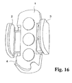
- FIG. 16 illustrates an article holding device disclosed in Patent Document 1 as a conventional example.
- This article holding device has a base 1, holding members 2 and 3, and a release button 4.
- the holding members 2 and 3 are provided in a direction orthogonal to a long direction of the base 1, and grip an article disposed on the base from both sides.
- at least one of the holding members 2 and 3 is provided to be capable of sliding so as to be able to change a width of gripping an article with the holding member 2 and the holding member 3 in accordance with a height of the article.
- the holding member 2 and the holding member 3 are urged in a direction of widening of the distance between the two, by an urging force from an urging member not illustrated.
- the release button 4 has a portion to be pressed and locking device provided on the opposite side. Also, the locking device of the release button 4 couple with a gear that rotates together with movement of the holding members 2 and 3. Here, the locking device of the release button 4 is urged to the abovementioned gear by an urging force from an urging member not illustrated.
- a force opposing the abovementioned urging force is applied to the abovementioned locking device, and the coupling between the release button 4 and the abovementioned gear is released, by pressing of the release button 4 (in opposition to the abovementioned urging force).
- the holding member 2 and the holding member 3 are moved by the abovementioned urging force up to a position where the distance between the two becomes maximal. Also, at this time, the distance between the holding member 2 and the holding member 3 is maintained by coupling of the engaging device of the release button 4 with the abovementioned gear.
- the release button 4 is pressed in a state in which the article is placed on the base 1, and pressing of the release button 4 is then stopped after the holding members 2 and 3 have been moved in a direction to move closer to each other in opposition to the abovementioned urging force up to contact the holding members 2 and 3 to both sides of the article, whereby the article is held.
- the release button 4 is pressed to release holding of the article.
- the coupling between the engaging device of the release button 4 and the abovementioned gear is thereby released, and the holding member 2 and the holding member 3 are moved by the abovementioned urging force up to a position where the distance between the two becomes maximal.
- Patent Document 1 German Patent Publication No. 19542720
- the abovementioned article holding device can stably hold an article without rattling and the state of holding of the article can be released at once by pressing of the release button 4, there are problems such as the following. Specifically, in such article holding device, because the engaging device of the release button 4 and the gear are always engaged as long as the release button 4 is not pressed, a clicking sound is produced by rotation of the gear while contacting the engaging device on the side of the release button 4 when the holding member 2 and the holding member 3 are slid in a direction narrowing the distance between the two.
- An object of the present invention is to solve problems such as the above, and to provide a holding tool to which a rotary damper can be easily added as needed.
- the present invention is an article holding device, comprising a base for placing an article, a holding member capable of sliding along a grip width of gripping an article, and locking device including a gear, a release button coupling and decoupling the gear, and an urging member applying an urging force in a direction of coupling the release button with the gear, for holding in a position after sliding and adjusting the holding member, wherein the locking device includes a rack provided on the holding member, a pinion engaging with the rack and being placed roughly coaxially with the gear, and a one-way clutch interposed between the gear and the pinion and configured to become disconnected from the gear and to slip only when the pinion is rotated in one direction.
- the locking device preferably further includes an urging member for applying an urging force for causing the engaging portion to couple with the gear, and a release button releasing the coupling between the engaging portion and the gear by being pressed.
- the one-way clutch preferably causes the pinion to slip against the gear when the holding member is slid in a direction of reducing the grip width, and preferably puts the pinion and the gear in the connected state when the holding member is slid in a direction of enlarging the grip width by pressing of the release button and releasing of the coupling between the engaging portion and the gear.
- the article holding device of the present invention is preferably switched between a housing position housed in a housing space on the side of a vehicle and a drawn-out position drawn out from the housing space. Also, the article holding device of the present invention is preferably fixed to a slider capable of sliding inside a housing embedded in the housing space, and is preferably switched by way of the slider between the housing position housed inside the housing and the drawn-out position drawn out from an opening provided on one end of the housing.
- the article holding device of the present invention is preferably connected to the slider by way of an adjustable connection device, and is preferably connected to be capable of adjusting an angle downward and to be capable of adjusting rotation to the left and right in the drawn-out position.
- an adjustable connection device preferably connected to be capable of adjusting an angle downward and to be capable of adjusting rotation to the left and right in the drawn-out position.
- a tilting mechanism described in Japanese Patent Application Publication No. 2010-023786 and a rotating mechanism and angle adjusting mechanism disclosed in Japanese Patent Application Publication No. 2004-210150 also may be included.
- the article holding device 9 of the present embodiment has a board-form base 1 for placing an article K, a holding member 2 disposed to be capable of sliding on one side of the base 1, an urging member S1 for applying an urging force to the holding member 2, and locking device 4 for holding in a position after sliding the holding member 2.
- the base 1 has a flat board part 10 for placing the article K, an extended part 11 provided on one end side in the long direction of the flat board part 10, and a holding piece part 12 provided roughly in the middle of one edge part following the long direction on the flat board part 10.
- the extended part 11 projects in a direction orthogonal to the surface direction of the flat board part 10.
- the holding piece part 12 projects in the same direction as the extended part 11 from the abovementioned one end side of the flat board part 10.
- the members described later are placed on the underside of the flat board part 10 of the base 1, that is, on the opposite side in the direction of projection of the extended part 11 and the holding piece part 12 of the flat board part 10, and the members are covered by a cover 17.
- An opening 13a cut out into a roughly rectangular shape is provided inside an edge part on the opposite side of the edge part in the short direction (width direction) of the flat board part 10 where the holding piece part 12 is provided.
- a roughly rectangular opening 13b cutting out one edge part in the width direction is provided near the extended part 11 on the edge part of the flat board part 10 where the holding piece part 12 is provided.
- boss-form shaft parts 10a respectively projecting in the width direction of the flat board part 10 are provided on both side parts of the edge part on the opposite side of the extended part 11 in the long direction of the flat board part 10.
- a buffering cushion material C1 of nonwoven cloth, or the like, is provided on the upper face of the flat board part 10.
- a plurality of placement spaces delineated by partition walls is provided on the underside of the flat board part 10.
- a pinion 44, a gear 38, a gear 40, a rotary damper 35, a clutch member 46 being one example of a one-way clutch, and the like, are placed in a placement space 14 provided toward the side of the extended part 11 from the middle in the long direction on the underside of the flat board part 10.
- a sliding board part 21 of the holding member 2, and the like are placed in a placement space 15 provided on the opposite side of the extended part 11 with respect to the placement space 14.
- an urging member S1 is placed in a placement space 15b provided adjacent to the placement space 15.
- a release button 3 is placed in a placement space 16 provided further to the side of the extended part 11 from the placement space 14.
- a rib 10b, a boss 10c, installation holes 10d, and a bearing part 16a are further provided on the underside of the flat board part 10.
- the rib 10b is provided following the width direction of the flat board part 10 on the opposite side of the extended part 10 in the long direction of the flat board 10.
- the boss 10c is provided in a position corresponding to a positioning hole 18c on the cover 17, to be described later, covering the underside of the flat board part 10, and couples with the positioning hole 18c.
- the installation holes 10d are installation holes provided in a plurality of places on the underside of the flat board part 10.
- the symbol 16a indicates a bearing part provided toward the side of the extended part 11 inside the placement space 16, to contact one end part of an urging member S2.
- a clearance part 15a where the height of the partition wall is formed lower than the other portions is provided on the partition wall delineating the placement space 14 and the placement space 15 so that the sliding board part 21 of the holding member 2 and the gear 40 do not collide.
- a rotating board 25 capable of rotating roughly 90 degrees, an urging member S3 for urging the rotating board 25 in a direction of standing up, and a pair of restricting pieces 27 for restricting the rotating board 25 so as not to rotate to the upper face side of the flat board part 10 are provided on an end part on the opposite side of the extended part 11 in the long direction of the flat board part 10.
- the rotating board 25 is urged by an urging member S3 placed on one side of the lower end side, with one end being stopped on the side of the rib 10b or the flat board part 10 and the other end pressing with a prescribed urging force, and is in contact with a restricting part 29 on the side of the restricting piece.
- a space 11a inside of the extended part 11 has a size sufficient for placement of an adjustable connection device 7 to be described later.
- This space 11a has a rectangular container form of a generally inverted concave form, and has a window part 11b cutting out a middle part of a rear wall part, clearance holes 11d provided on an upper face inside the concavity, and locking hole 11c for cover provided on an upper side of the concavity on the rear wall part.
- the holding member 2 has a roughly L-shaped body 20, and has a sliding board part 21, and a holding piece part 22 provided roughly perpendicular to the sliding board part 21.
- a rack 23 is formed on one side face of the sliding board part 21.
- a bearing part 24 projecting in a direction orthogonal to the direction of sliding of the sliding board part 21 is provided on the other side face of the sliding board part 21.
- the rack 23 is provided along an end face of a step part provided on the abovementioned one side face.
- the sliding board part 21 of the holding member 2 is placed in the opening 13a and the placement space 15 provided on the flat board part 10 of the base 1, so as to be capable of sliding in the width direction of the flat board part 10 of the base 1, that is, the direction (sliding direction) indicated by the arrow in FIGS. 10 and 12 .
- the bearing part 24 of the holding member 2 is placed in contact with one end of the urging member S1 disposed in the placement space 15b of the base 1.
- the other end of this urging member S1 contacts the inner end face of the placement space 15b.
- the urging member S1 is a coil spring.
- the urging member S1 applies an urging force moving to return the sliding board part 21 to the position indicated in FIG. 7 by way of the bearing part 24.
- a buffering cushion material C2 is installed on the mutually opposite faces of the holding piece part 12 and the holding piece part 22. Also, when the sliding board part 21 is slid, the rack 23 moves following the clearance part 15a, and the bearing part 24 moves following a clearance part provided on the rib delineating the placement space 15b.
- the release button 3 has a body 30, an operating part 31, a cutout part 32, and a cutout part 34.
- the maximum width of the body 30 is roughly equal to the inner width of the placement part placement space 16.
- the operating part 31 is exposed from the opening 13b provided on the flat board part 10 when the body 30 of the release button 3 is placed in the placement space 16.
- the cutout part 32 and the cutout part 34 are portions where both edges following the long direction of the body 30 are cut out inside. Of these, an engaging portion 33 for coupling with the gear 40 is provided in the cutout part 32, and the urging member S2 is disposed in the cutout part 34.
- the urging member S2 is a coil spring, one end thereof contacts the bearing part 16a provided in the placement space 16 as mentioned above, and the other end contacts an end face of the cutout part 34.
- the engaging portion 33 provided in the cutout part 32 is coupled with the teeth provided on the outer perimeter of the gear 40, by the urging force applied to the body 30 of the release button 3 by the urging member S2.
- the engaging portion 33 is formed in an acute angular form so as to couple easily with the teeth on the outer perimeter of the gear 40.
- the body 30 slides in the width direction of the flat board part 10 in opposition to the abovementioned applied urging force. Also, the engaging portion 33 separates from the gear 40 (the coupling is released), and the gear 40 becomes capable of rotation.
- the release button 3 returns to the position before pressing by the urging force from the urging member S2.
- the locking device 4 include the gear 40 rotating centered on a rotating shaft fixed to the base 1, the urging member S2 urging the engaging portion 33 integrally provided with the release button 3 in the direction of coupling with the gear 40, the rack 23 provided on the holding member 2, the pinion 44 engaging with the rack 23 and rotating centered on the same rotating shaft as of the gear 40, and the clutch member 46 disposed between the gear 40 and the pinion 44.
- the locking device 4 also includes the rotary damper 35 and the gear 38 interposed between a damping gear 37 of the damper 35 and the pinion 44.
- the clutch member 46 is a one-way clutch that becomes disconnected from the gear 40 and slips only when the pinion 44 is rotated in one direction.
- the gear 40, pinion 44, and clutch member 36 which are the main members of the locking device 4, constitute a double-gear one-way clutch together with the release button 3.
- the gear 40 couples the engaging portion 33 in the state when the release button 3 is not pressed, and the coupling with the engaging portion 33 is released and the gear 40 becomes capable of rotation by pressing of the release button 3, as described above.
- a recessed part 42 hollowed out in a circular shape is provided on one of the upper and lower faces of the gear 40.
- a boss part 43 projecting perpendicularly to the upper and lower faces of the gear 40 is provided in the center of the recessed part 42.
- a shaft hole is provided in the center of this boss part 43.
- the depth of the hollow of the recessed part 42 is shallower than the thickness of the pinion 44. Accordingly, teeth on the outer perimeter of the pinion 44 protrude from the recessed part 42 when the pinion 44 is placed in the recessed part 42. Also, these protruding teeth engage with the rack 23 provided on the holding member 2. Accordingly, for example, when the holding member 2 is slid from the position illustrated in FIG. 9 to the position indicated by the arrow in FIGS. 10 and 12 , the pinion 44 is rotated along with that sliding.
- the pinion 44 has formed an installation hole 45 for installing the clutch member 46 in the center part.
- the clutch member 46 has a through-hole 47 provided in the center, and has a D-cut part 48 provided on the outer perimeter. Also, the clutch member 46 is pressed against the installation hole 45 of the pinion 44 by way of the D-cut part 48. Also, the clutch member 46 is connected to the gear 40 by pressing of the boss part 43 of the gear 40 into the through-hole 47 of the clutch member 46.
- the members of the locking device 4 are assembled in this manner, and the shaft part 14a provided in the placement space 14 is then insertion-coupled in the shaft hole of the boss part 43 in a state in which the pinion 44 is turned downward, whereby the entirety is placed on the axial line of the shaft part 14a.
- the gear 38 and the rotary damper 35 are first incorporated in the placement space 14 when the members of the locking device 4 are assembled in this manner.
- the gear 38 is such that a shaft hole provided therein is insertion-coupled with a shaft part, not illustrated, provided in the placement space 14, and teeth on the outer perimeter thereof are engaged with the pinion 44.
- the rotary damper 35 has a body 36 and a gear 37, and is damped with a fluid injected inside the body 36.
- the gear 37 and the gear 38 engage when the body 36 of the rotary damper 36 is installed in the placement space 14 by way of screws M2, and the like.
- the holding member 2 is thereby damped so as not to be slid rapidly by the urging force of the urging member S1.
- the cover 17 is installed on the base 1 so as to cover the lower face of the base 1 after the members of the locking device 4, and the like, are placed on the side of the flat board part 10 in the above manner.
- the cover 17 includes a board part 18 corresponding to the flat board part 10, and a step part 19 corresponding to the extended part 11.
- An opening 18a in which a part of the sliding part 21 of the holding member 2 is exposed, an opening 18b in which a part of the operating part 31 on the button side is exposed, the abovementioned positioning hole 18c, an insertion-coupling hole 18d allowing clearance for the shaft part 14a, and a plurality of screw insertion holes 18e are formed on the board part 18.
- a boss part 19a to be inserted in the locking hole 11c, an insertion-coupling hole 19b corresponding to the adjustable connection device 7, and installation holes 19c for screwing in the screws M2 are formed on the step part 19.
- the cover 17 is attached to the base 1 by screwing a plurality of screws M into the insertion holes 18e provided on the cover 17 and the installation holes 10d provided on the base 1.
- the above article holding device 9 is moved in and out of the housing 5 by way of the slider 6 to be switched between the housing position and the drawn-out position, and is supported to be capable of adjusting an angle downward and to be capable of adjusting rotation to the left and right by way of the adjustable connection device 7 in the drawn-out position, for example, as illustrated in FIGS. 1 to 3 and 14 .
- the housing 5 is a roughly parallelepiped-shaped case covered by an upper face 50, a lower face 51, side faces 52, and a back face 53, and has an opening provided on one end in the long direction.
- This housing 5 is fixed, for example, in a state being embedded in an instrument panel, or the like, of an automobile.
- the upper face 50 has a long and slender through-slot 54 provided from front to back, a rack part 55 provided on an inside end face of the through-slot 54 and extending in the long direction, for engaging with the gear 37 of the rotary damper 35 to be described later, and a support hole 50a running through in a position in the middle from left to right on the rear end side.
- a rocking member 80 constituting latch device 8 is pivotally supported to be capable of rotation in the support hole 50a.
- the rocking member 80 constitutes a push-push locking mechanism of the latch device 8 together with a heart cam groove 83 on the slider side to be described later.
- the rocking member 80 includes a shaft part 81 for installation placed projecting on an upper face on one end of the rocking member 80, to be insertion-coupled in the support hole 50a, and a pin part 82 placed projecting on a lower face on the other end of the rocking member 80.
- both side faces 52 have an installation part 56 placed projecting on the outside at the front, and have a guide slot 57 extending from front to back on the inside as a guide for rocking of the slider 6.
- a spring stopping part 58 is provided on the lower face 51 on the side of the opening.
- the symbol 59 indicates an opening cut out toward the rear from slightly toward the depth from the opening, positioned roughly in the middle from left to right.
- the slider 6 has a small block form, and integrally has a heart cam groove 83 provided in an upper recessed part formed in a middle part 60 from left to right, a damper installation hole 66a provided in an upper recessed part 66 formed in a left-side part 61, a hole part 67 running through a right-side part 62 from top to bottom and supporting a coil spring 85 to be capable of rotation, guide ribs 63 provided on left and right side faces, to be insertion-coupled in corresponding guide slots 57 on the sides of the housing, an inverted concave-form part 64 for installation provided on a lower face of the middle part 60, and an inverted concave-form part 65 for guiding provided on a lower face of the right-side part, allowing clearance for a spring 87.
- the rotary damper 35 is inserted inside the installation hole 66a, and the coil spring 85 is supported in the hole part 67.
- the damper 35 is the same as the abovementioned damper 35.
- a gear 37 damped by a fluid is provided inside a body 36, and the gear 37 projects from the upper recessed part 66 and engages with the rack part 55 disposed on the side of the housing 5 in a state in which the body 36 is installed in the installation hole 66a.
- the coil spring 85 has a band-form spring wound onto a corresponding part of a body 86, and is supported to be capable of rotation in a state in which shaft parts 86a on both sides are insertion-coupled in corresponding recessed parts of the hole part 67.
- the spring 87 is drawn out in the course of movement of the slider 6 to the depth part of the housing 5 in a state in which a drawn-out end 87a of the spring 87 is stopped on a stopping part 58 on the side of the housing, and the coil spring 85 urges the slider 6 and the article holding device 9 in the direction of projecting to the front of the housing 5 by virtue of the return force thereof.
- the heart cam groove 83 locks the slider 6 and the article holding device 9 in the housing position in the housing 2 in opposition to the urging force of the coil spring 85 by coupling of the pin part 82 in a locking recessed part provided on the perimeter of a protruding island.
- the slider 6 retreats slightly when being pressed by way of the article holding device 9 from this state, and the pin part 82 is unlocked from the locking recessed part.
- the article holding device 9 is locked in the housing position by operation of the pin part 82 and the heart cam 83, having been pushed inside the housing in opposition to the urging force of the coil spring 85 by the slider 6, and when the article holding device 9 is next pushed in the direction of pushing inward and the hand is let go, the locking is unlocked and the article holding device 9 is enabled to advance to the drawn-out position by the urging force of the coil spring 85 by way of the slider 6.
- the adjustable connection device 7 includes a slider-side installation body 70, a base-side installation body 79, and a movable body 74 interposed between the installation bodies 70 and 79, as illustrated in FIG. 15 .
- the installation body 70 has integrally formed a horizontal board-form attachment part 71 placed in the inverted concave-form part 64 on the side of the slider, a pair of connecting parts 72 having bent a portion on the near side in the drawing of the attachment part 71 roughly into a U shape, to be placed inside the extended part 11 on the side of the base, and a circular bulging part 73 on the outer face side of each connecting part 72.
- Connecting holes for press-connection are respectively provided on the connecting parts 72 and the bulging parts 73 on both sides.
- a movable body 74 is bent roughly into an angle-bracket shape having a size sufficient to be placed between both connecting parts.
- a shaft part 78 is provided in a center part of a middle part 75 of the angle-bracket shape. Shaft parts to be insertion-coupled in the connecting holes are provided on both side parts 76 of the angle-bracket shape.
- the movable part 74 is connected to the installation body 70, in a state in which both side parts 76 are placed between both connecting parts 72 and each aforementioned connecting part is insertion-coupled in the corresponding aforementioned connecting hole, to be capable of being adjusted to an arbitrary angle in the front-to-back direction in the same drawing, that is, downward, specified in claim 5, and of being held elastically after adjustment.
- the installation body 79 includes a long and slender board, and has installation holes 79a provided on both sides, and a coupling hole 79b running through a center part.
- the installation body 79 is connected to the movable body 74 by insertion-coupling between the shaft part 78 and the coupling hole 79b, and is connected with the shaft part 78 as fulcrum, to be capable of being adjusted in the direction of the arrow in the same drawing, that is, to the left and right, specified in claim 5, and of being held elastically after adjustment.
- the numeral 68 in FIG. 14 indicates a cover for covering the main parts, being additionally provided to the adjustable connection device 7.
- the installation body 79 of the above adjustable connection device 7 is fixed to the step part 19 on the side of the cover attached to the base 1 with two screws M2 being screwed into the corresponding installation holes 19c. At that time, the projecting end of the shaft part 78 is allowed clearance by the insertion-coupling hole 19.
- the article holding device 9 is such that only the attachment part 71 of the installation body 70 is projected to the outside from the window part 11b on the side of the extended part in the state in which the adjustable connection device 7 is attached.
- the attachment part 71 is then fastened by screws to the concave-form part 64 on the side of the slider.
- the article holding device 9 is thus switched between the housing position and the drawn-out position with respect to the housing 5 by way of the slider 6, and is used in a most easily used mode by way of the adjustable connection device 7 in the drawn-out position.
- a mode in which the article holding device 9 is installed in an instrument panel of a vehicle by way of the housing 5 is next described as an example while referring to the drawings.
- the housing 5 is normally attached in a state being embedded in an instrument panel, console, or other suitable place in a vehicle.
- the article holding device 9 may be received in a receiving part corresponding to the housing 5, integrally provided in an instrument panel or any kind of console in a vehicle, instead of the housing 5.
- FIG. 1 illustrates a state in which the article holding device 9 is in the housing position being stored inside the housing 5, that is, the article holding device 9 and the slider 6 are in the housing position.
- the slider 6 and the article holding device 9 are locked by operation of the pin part 82 and the heart cam groove 83 in the standard position inside the housing 5 in opposition to the urging force of the coil spring 85.
- the rotating board 25 is pushed by a user's finger as illustrated in FIG.
- FIG. 2 illustrates a state in which the article-holding device 9 is thus drawn out to the drawn-out position. At this time, the advancing movement of the article holding device 9 and the slider 6 is damped by way of the damper 35.
- FIGS. 3 to 5 are an example in which the article holding device 9 is made usable in a posture most convenient for the operator by adjusting the angle of tilt or angle of rotation by way of the abovementioned adjustable connection device 7 from the above drawn-out state.
- the article holding device 9 described above is such that, when in a state not in use, the distance, that is, the grip width between the holding piece part 22 on the holding member 2 and the holding piece part 12 on the stationary side was brought to the maximum width L by the urging force of the urging member S1, as illustrated in FIGS. 7 to 9 . Also, in the case when holding a cellular telephone K or other article in the article holding device 9, illustrated in FIG. 5 , the article is placed between the holding piece part 22 and the holding piece part 12 of the article holding device 9 in the abovementioned state not in use, and the holding member 2 is then operated to slide in the direction indicated by the arrow in FIGS. 10 and 12 .
- the holding member 2 moves to return to the original position by the urging force of the urging member S1. Also, at this time, the pinion 44 engaged with the rack 23 on the side of the holding member 2 relays counterclockwise rotational torque to the gear 40. However, the gear 40 is coupled with the engaging portion 33 and therefore cannot rotate. Accordingly, the holding member 2 stops at the position where pressing was stopped. The state in which the article is held between the holding piece part 22 and the holding piece part 12 is thereby maintained.
- the release button 3 When removing the held article from the article holding device 9, the release button 3 is pressed in opposition to the urging force of the urging member S2. The coupling between the gear 40 and the engaging portion 33 is thus released and the gear 40 becomes in a state capable of rotation.
- the holding member 2 thereby returns to the original initial force (the grip width becomes L) by the urging force of the urging member S1.
- the clutch member 46 becomes clutch-on, and the gear 40 and the pinion 44 rotate clockwise together.
- the pinion 44 is engaged with the damper 35 by way of the second gear 38 and is therefore damped, and the holding member 2 thereby returns gently.
- the defect of an impact sound can therefore be eliminated ⁇ even when the urging force of the urging member S1 is set strongly.
- the damper 35 is adopted because of the increase of quality, but there is no problem even if it is omitted.
- the article holding device 9 is such that the pinion 44 becomes in a state not connected with the gear 40 and slips (the pinion 44 is rotated alone) when the pinion 44 is rotated in one direction by way of the clutch member 46 (one-way clutch), and the pinion 44 is connected with the gear 40 and rotates in synchronization when the pinion 44 is rotated in the direction opposite the abovementioned one direction.
- the article holding device 9 of the present embodiment can prevent the production of a sound (the abovementioned clicking sound) caused by engagement between the engaging portion 33 and the gear 40 when the pinion 44 is rotated in the abovementioned one direction, compared with an article holding device in which the gear 40 always operates in linkage with the sliding of the holding member 2 regardless of the sliding direction of the holding member 2.
- the pinion 44 is rotated in the abovementioned one direction when the holding member 2 is slid in the direction of reducing the grip width, but in another example of the article holding device 9, the pinion 44 may be rotated in the abovementioned rotation when the holding member 2 is slid in the direction of enlarging the grip width.
- the pinion 44 engaging with the rack 23 on the side of the holding member 2 is provided, and (the damping gear 37 of) the rotary damper 35 can therefore be easily connected to the pinion 44 by way of the gear 38.
- the rotary damper 35 may be directly connected to the pinion 44 instead of the present example.
- the pinion slips when the holding member 2 is slid in the direction of reducing the grip width (for example, to hold an article). Accordingly, the production of a sound caused by engagement between the engaging portion 33 and the gear 40 can be prevented.
- the holding member 2 is slid by urging force in the direction of enlarging the grip width when the release button 3 is pressed (for example, to again remove the article from the held state). Also, at this time, the holding member 2 returns to the original position while sliding gently rather than returning to the original position suddenly, because of the presence of the abovementioned rotary damper 35.
- the article holding device 9 can be received inside a housing space on the side of a vehicle, or in a housing 5 installed in an embedded state in that housing space.
- the article holding device 9 therefore does not occupy space inside the vehicle compartment when not in use, and the comfortableness of the vehicle compartment can be improved.
- the article holding device 9 according to the present embodiment can be set so that the long direction is oriented downward from the slider 6 or is oriented sideways in the state drawn out to the drawn-out position, and adjustment of the angle, and the like, can thus be performed easily.
Landscapes
- Engineering & Computer Science (AREA)
- General Engineering & Computer Science (AREA)
- Mechanical Engineering (AREA)
- Vehicle Step Arrangements And Article Storage (AREA)
- Fittings On The Vehicle Exterior For Carrying Loads, And Devices For Holding Or Mounting Articles (AREA)
- Telephone Set Structure (AREA)
Abstract
Description
- The present invention relates to an article holding device when using an article, particularly a cellular telephone, music player, or the like, in a state being held on a dashboard, or the like, inside a vehicle compartment.
- All kinds of article holding devices have been used from the past for holding cellular telephones and other articles in a gripped state on a dashboard, or the like, inside a vehicle compartment. Also, of such article holding devices, there is a type in which a grip width is easily variably adjusted whereby articles having different width dimensions can be held.
FIG. 16 illustrates an article holding device disclosed inPatent Document 1 as a conventional example. This article holding device has abase 1, holdingmembers release button 4. Theholding members base 1, and grip an article disposed on the base from both sides. Here, at least one of theholding members holding member 2 and theholding member 3 in accordance with a height of the article. - Also, the
holding member 2 and theholding member 3 are urged in a direction of widening of the distance between the two, by an urging force from an urging member not illustrated. Therelease button 4 has a portion to be pressed and locking device provided on the opposite side. Also, the locking device of therelease button 4 couple with a gear that rotates together with movement of theholding members release button 4 is urged to the abovementioned gear by an urging force from an urging member not illustrated. Also, a force opposing the abovementioned urging force is applied to the abovementioned locking device, and the coupling between therelease button 4 and the abovementioned gear is released, by pressing of the release button 4 (in opposition to the abovementioned urging force). - Also, when the coupling between the
release button 4 and the abovementioned gear is released by pressing of therelease button 4, theholding member 2 and theholding member 3 are moved by the abovementioned urging force up to a position where the distance between the two becomes maximal. Also, at this time, the distance between theholding member 2 and theholding member 3 is maintained by coupling of the engaging device of therelease button 4 with the abovementioned gear. Also, to hold an article, therelease button 4 is pressed in a state in which the article is placed on thebase 1, and pressing of therelease button 4 is then stopped after theholding members holding members release button 4 is pressed to release holding of the article. The coupling between the engaging device of therelease button 4 and the abovementioned gear is thereby released, and theholding member 2 and theholding member 3 are moved by the abovementioned urging force up to a position where the distance between the two becomes maximal. - Patent Document 1: German Patent Publication No.
19542720 - Although the abovementioned article holding device can stably hold an article without rattling and the state of holding of the article can be released at once by pressing of the
release button 4, there are problems such as the following. Specifically, in such article holding device, because the engaging device of therelease button 4 and the gear are always engaged as long as therelease button 4 is not pressed, a clicking sound is produced by rotation of the gear while contacting the engaging device on the side of therelease button 4 when theholding member 2 and theholding member 3 are slid in a direction narrowing the distance between the two. Also, because theholding members release button 4 is pressed, an impact sound is produced at that time giving discomfort to the user. The problems such as the above are the same also in the case of a configuration in which an urging force is applied to theholding members - An object of the present invention is to solve problems such as the above, and to provide a holding tool to which a rotary damper can be easily added as needed.
- In order to achieve the abovementioned object, the present invention is an article holding device, comprising a base for placing an article, a holding member capable of sliding along a grip width of gripping an article, and locking device including a gear, a release button coupling and decoupling the gear, and an urging member applying an urging force in a direction of coupling the release button with the gear, for holding in a position after sliding and adjusting the holding member, wherein the locking device includes a rack provided on the holding member, a pinion engaging with the rack and being placed roughly coaxially with the gear, and a one-way clutch interposed between the gear and the pinion and configured to become disconnected from the gear and to slip only when the pinion is rotated in one direction.
- Also, in the article holding device of the present invention, the locking device preferably further includes an urging member for applying an urging force for causing the engaging portion to couple with the gear, and a release button releasing the coupling between the engaging portion and the gear by being pressed.
- Also, in the article holding device of the present invention, the one-way clutch preferably causes the pinion to slip against the gear when the holding member is slid in a direction of reducing the grip width, and preferably puts the pinion and the gear in the connected state when the holding member is slid in a direction of enlarging the grip width by pressing of the release button and releasing of the coupling between the engaging portion and the gear.
- Also, the article holding device of the present invention is preferably switched between a housing position housed in a housing space on the side of a vehicle and a drawn-out position drawn out from the housing space.
Also, the article holding device of the present invention is preferably fixed to a slider capable of sliding inside a housing embedded in the housing space, and is preferably switched by way of the slider between the housing position housed inside the housing and the drawn-out position drawn out from an opening provided on one end of the housing. - Also, the article holding device of the present invention is preferably connected to the slider by way of an adjustable connection device, and is preferably connected to be capable of adjusting an angle downward and to be capable of adjusting rotation to the left and right in the drawn-out position. A tilting mechanism described in Japanese Patent Application Publication No.
2010-023786 2004-210150 -
-
FIG. 1 is a diagram of the case when the article holding device of the present embodiment is in the housing position housed in the housing. -
FIG. 2 is a diagram of the case when the article holding device of the present embodiment is in the drawn-out position drawn out from the housing. -
FIG. 3 is a diagram of the case when the article holding device of the present embodiment is in an in-use position. -
FIG. 4 is a diagram of the case when the article holding device of the present embodiment is in an in-use position different from that inFIG. 3 . -
FIG. 5 is a diagram of the case when the article holding device of the present embodiment is in an in-use position different from those inFIGS. 3 and 4 , and is a diagram of a state in which the article holding device is holding a cellular telephone as the article. -
FIG. 6 is a generalized perspective view showing the article holding device of the present embodiment viewed from the bottom in a state in which the cover is removed. -
FIG. 7 is a plan view showing a state in which the cover of the article holding device of the present embodiment is removed and the grip width of the holding members is at maximum width L. -
FIG. 8 is a side view showing a state in which the cover of the article holding device of the present embodiment is removed and the grip width of the holding members is at maximum width L. -
FIG. 9 is a bottom view showing a state in which the cover of the article holding device of the present embodiment is removed and the grip width of the holding members is at maximum width L. -
FIG. 10 is a plan view showing a state in which the grip width of the holding members of the article holding device of the present embodiment is reduced to L1. -
FIG. 11 is a side view showing a state in which the grip width of the holding members of the article holding device of the present embodiment is reduced to L1. -
FIG. 12 is a bottom view showing a state in which the grip width of the holding members of the article holding device of the present embodiment is reduced to L1. -
FIG. 13 is a generalized exploded perspective view showing the essential parts of the abovementioned article holding device. -
FIG. 14 is a generalized exploded perspective view showing the housing side of the abovementioned article holding device. -
FIG. 15 is a structural diagram showing the structure supporting the abovementioned article holding device to be capable of angle adjustment and rotation. -
FIG. 16 is an explanatory diagram showing a conventional article holding device disclosed inPatent Document 1. - An embodiment of the present invention is described below while referring to the attached drawings. The structure of the
article holding device 9, the structure for supporting and receiving thearticle holding device 9, and the operating characteristics of thearticle holding device 9 are described in detail in sequence in the description below. - The article holding
device 9 of the present embodiment has a board-form base 1 for placing an article K, aholding member 2 disposed to be capable of sliding on one side of thebase 1, an urging member S1 for applying an urging force to theholding member 2, andlocking device 4 for holding in a position after sliding theholding member 2. - The
base 1 has aflat board part 10 for placing the article K, anextended part 11 provided on one end side in the long direction of theflat board part 10, and aholding piece part 12 provided roughly in the middle of one edge part following the long direction on theflat board part 10. The extendedpart 11 projects in a direction orthogonal to the surface direction of theflat board part 10. Also, theholding piece part 12 projects in the same direction as theextended part 11 from the abovementioned one end side of theflat board part 10. The members described later are placed on the underside of theflat board part 10 of thebase 1, that is, on the opposite side in the direction of projection of theextended part 11 and theholding piece part 12 of theflat board part 10, and the members are covered by acover 17. An opening 13a cut out into a roughly rectangular shape is provided inside an edge part on the opposite side of the edge part in the short direction (width direction) of theflat board part 10 where theholding piece part 12 is provided. Also, a roughlyrectangular opening 13b cutting out one edge part in the width direction is provided near the extendedpart 11 on the edge part of theflat board part 10 where theholding piece part 12 is provided. Also, boss-form shaft parts 10a respectively projecting in the width direction of theflat board part 10 are provided on both side parts of the edge part on the opposite side of theextended part 11 in the long direction of theflat board part 10. Also, a buffering cushion material C1 of nonwoven cloth, or the like, is provided on the upper face of theflat board part 10. - Also, a plurality of placement spaces delineated by partition walls is provided on the underside of the
flat board part 10. For example, apinion 44, agear 38, agear 40, arotary damper 35, aclutch member 46, being one example of a one-way clutch, and the like, are placed in aplacement space 14 provided toward the side of theextended part 11 from the middle in the long direction on the underside of theflat board part 10. Also, a slidingboard part 21 of the holdingmember 2, and the like, are placed in aplacement space 15 provided on the opposite side of theextended part 11 with respect to theplacement space 14. Also, an urging member S1 is placed in aplacement space 15b provided adjacent to theplacement space 15. Also, arelease button 3 is placed in aplacement space 16 provided further to the side of theextended part 11 from theplacement space 14. - A
rib 10b, aboss 10c,installation holes 10d, and abearing part 16a are further provided on the underside of theflat board part 10. Therib 10b is provided following the width direction of theflat board part 10 on the opposite side of theextended part 10 in the long direction of theflat board 10. Theboss 10c is provided in a position corresponding to apositioning hole 18c on thecover 17, to be described later, covering the underside of theflat board part 10, and couples with thepositioning hole 18c. The installation holes 10d are installation holes provided in a plurality of places on the underside of theflat board part 10. Thesymbol 16a indicates a bearing part provided toward the side of theextended part 11 inside theplacement space 16, to contact one end part of an urging member S2. - A
clearance part 15a where the height of the partition wall is formed lower than the other portions is provided on the partition wall delineating theplacement space 14 and theplacement space 15 so that the slidingboard part 21 of the holdingmember 2 and thegear 40 do not collide. - A rotating
board 25 capable of rotating roughly 90 degrees, an urging member S3 for urging the rotatingboard 25 in a direction of standing up, and a pair of restrictingpieces 27 for restricting the rotatingboard 25 so as not to rotate to the upper face side of theflat board part 10 are provided on an end part on the opposite side of theextended part 11 in the long direction of theflat board part 10. Also, the rotatingboard 25 is urged by an urging member S3 placed on one side of the lower end side, with one end being stopped on the side of therib 10b or theflat board part 10 and the other end pressing with a prescribed urging force, and is in contact with a restrictingpart 29 on the side of the restricting piece. This makes holding possible in a case such as when the article as an object is longer than theflat board part 10, by rotating the rotatingboard 25 in opposition to the urging force of the urging member S3 to lengthen theflat board part 10 in the amount of the rotating board. - As opposed to this, a
space 11a inside of theextended part 11 has a size sufficient for placement of anadjustable connection device 7 to be described later. Thisspace 11a has a rectangular container form of a generally inverted concave form, and has awindow part 11b cutting out a middle part of a rear wall part,clearance holes 11d provided on an upper face inside the concavity, and lockinghole 11c for cover provided on an upper side of the concavity on the rear wall part. - The holding
member 2 has a roughly L-shapedbody 20, and has a slidingboard part 21, and a holdingpiece part 22 provided roughly perpendicular to the slidingboard part 21. Arack 23 is formed on one side face of the slidingboard part 21. Also, a bearingpart 24 projecting in a direction orthogonal to the direction of sliding of the slidingboard part 21 is provided on the other side face of the slidingboard part 21. Also, therack 23 is provided along an end face of a step part provided on the abovementioned one side face. The slidingboard part 21 of the holdingmember 2 is placed in theopening 13a and theplacement space 15 provided on theflat board part 10 of thebase 1, so as to be capable of sliding in the width direction of theflat board part 10 of thebase 1, that is, the direction (sliding direction) indicated by the arrow inFIGS. 10 and 12 . Also, the bearingpart 24 of the holdingmember 2 is placed in contact with one end of the urging member S1 disposed in theplacement space 15b of thebase 1. Also, the other end of this urging member S1 contacts the inner end face of theplacement space 15b. In the present example, the urging member S1 is a coil spring. - When the sliding
board part 21 of the holdingmember 2 is slid in the abovementioned sliding direction, the space between the bearingpart 24 of the holdingmember 2 and the inner end face of theplacement space 15b is narrowed, and the urging member S1 is compressed. That is, when the slidingboard part 21 of the holdingmember 2 is slid in the abovementioned sliding direction, the slidingboard part 21 comes to be slid in opposition to the urging force applied to the slidingboard part 21 by way of the bearingpart 24 from the urging member S1. Accordingly, for example, when the slidingboard part 21 of the holdingmember 2 is slid so that the grip width between the holdingpiece part 12 and the holdingpiece part 22 is narrowed from the width (initial width) indicated by L inFIG. 7 to the width indicated by L1 inFIG. 10 , the urging member S1 applies an urging force moving to return the slidingboard part 21 to the position indicated inFIG. 7 by way of the bearingpart 24. Also, a buffering cushion material C2 is installed on the mutually opposite faces of the holdingpiece part 12 and the holdingpiece part 22. Also, when the slidingboard part 21 is slid, therack 23 moves following theclearance part 15a, and the bearingpart 24 moves following a clearance part provided on the rib delineating theplacement space 15b. - The
release button 3 has abody 30, an operatingpart 31, acutout part 32, and acutout part 34. The maximum width of thebody 30 is roughly equal to the inner width of the placementpart placement space 16. The operatingpart 31 is exposed from theopening 13b provided on theflat board part 10 when thebody 30 of therelease button 3 is placed in theplacement space 16. Thecutout part 32 and thecutout part 34 are portions where both edges following the long direction of thebody 30 are cut out inside. Of these, an engagingportion 33 for coupling with thegear 40 is provided in thecutout part 32, and the urging member S2 is disposed in thecutout part 34. In the present example, the urging member S2 is a coil spring, one end thereof contacts thebearing part 16a provided in theplacement space 16 as mentioned above, and the other end contacts an end face of thecutout part 34. Also, the engagingportion 33 provided in thecutout part 32 is coupled with the teeth provided on the outer perimeter of thegear 40, by the urging force applied to thebody 30 of therelease button 3 by the urging member S2. In the present example, the engagingportion 33 is formed in an acute angular form so as to couple easily with the teeth on the outer perimeter of thegear 40. - When the operating
part 31 of therelease button 3 exposed from theopening 13b is pressed, thebody 30 slides in the width direction of theflat board part 10 in opposition to the abovementioned applied urging force. Also, the engagingportion 33 separates from the gear 40 (the coupling is released), and thegear 40 becomes capable of rotation. When pressing of therelease button 3 is stopped, therelease button 3 returns to the position before pressing by the urging force from the urging member S2. - The
locking device 4 include thegear 40 rotating centered on a rotating shaft fixed to thebase 1, the urging member S2 urging the engagingportion 33 integrally provided with therelease button 3 in the direction of coupling with thegear 40, therack 23 provided on the holdingmember 2, thepinion 44 engaging with therack 23 and rotating centered on the same rotating shaft as of thegear 40, and theclutch member 46 disposed between thegear 40 and thepinion 44. Thelocking device 4 also includes therotary damper 35 and thegear 38 interposed between a dampinggear 37 of thedamper 35 and thepinion 44. - In the present example, the
clutch member 46 is a one-way clutch that becomes disconnected from thegear 40 and slips only when thepinion 44 is rotated in one direction. Also, thegear 40,pinion 44, andclutch member 36, which are the main members of thelocking device 4, constitute a double-gear one-way clutch together with therelease button 3. Thegear 40 couples the engagingportion 33 in the state when therelease button 3 is not pressed, and the coupling with the engagingportion 33 is released and thegear 40 becomes capable of rotation by pressing of therelease button 3, as described above. A recessedpart 42 hollowed out in a circular shape is provided on one of the upper and lower faces of thegear 40. Also, aboss part 43 projecting perpendicularly to the upper and lower faces of thegear 40 is provided in the center of the recessedpart 42. Also, a shaft hole is provided in the center of thisboss part 43. In the present example, the depth of the hollow of the recessedpart 42 is shallower than the thickness of thepinion 44. Accordingly, teeth on the outer perimeter of thepinion 44 protrude from the recessedpart 42 when thepinion 44 is placed in the recessedpart 42. Also, these protruding teeth engage with therack 23 provided on the holdingmember 2. Accordingly, for example, when the holdingmember 2 is slid from the position illustrated inFIG. 9 to the position indicated by the arrow inFIGS. 10 and 12 , thepinion 44 is rotated along with that sliding. - The
pinion 44 has formed aninstallation hole 45 for installing theclutch member 46 in the center part. Theclutch member 46 has a through-hole 47 provided in the center, and has a D-cutpart 48 provided on the outer perimeter. Also, theclutch member 46 is pressed against theinstallation hole 45 of thepinion 44 by way of the D-cutpart 48. Also, theclutch member 46 is connected to thegear 40 by pressing of theboss part 43 of thegear 40 into the through-hole 47 of theclutch member 46. - The members of the
locking device 4 are assembled in this manner, and theshaft part 14a provided in theplacement space 14 is then insertion-coupled in the shaft hole of theboss part 43 in a state in which thepinion 44 is turned downward, whereby the entirety is placed on the axial line of theshaft part 14a. Thegear 38 and therotary damper 35 are first incorporated in theplacement space 14 when the members of thelocking device 4 are assembled in this manner. Thegear 38 is such that a shaft hole provided therein is insertion-coupled with a shaft part, not illustrated, provided in theplacement space 14, and teeth on the outer perimeter thereof are engaged with thepinion 44. Therotary damper 35 has abody 36 and agear 37, and is damped with a fluid injected inside thebody 36. Thegear 37 and thegear 38 engage when thebody 36 of therotary damper 36 is installed in theplacement space 14 by way of screws M2, and the like. The holdingmember 2 is thereby damped so as not to be slid rapidly by the urging force of the urging member S1. - The
cover 17 is installed on thebase 1 so as to cover the lower face of thebase 1 after the members of thelocking device 4, and the like, are placed on the side of theflat board part 10 in the above manner. Thecover 17 includes aboard part 18 corresponding to theflat board part 10, and astep part 19 corresponding to theextended part 11. Anopening 18a in which a part of the slidingpart 21 of the holdingmember 2 is exposed, anopening 18b in which a part of the operatingpart 31 on the button side is exposed, theabovementioned positioning hole 18c, an insertion-coupling hole 18d allowing clearance for theshaft part 14a, and a plurality ofscrew insertion holes 18e are formed on theboard part 18. Aboss part 19a to be inserted in thelocking hole 11c, an insertion-coupling hole 19b corresponding to theadjustable connection device 7, andinstallation holes 19c for screwing in the screws M2 are formed on thestep part 19. Also, thecover 17 is attached to thebase 1 by screwing a plurality of screws M into theinsertion holes 18e provided on thecover 17 and theinstallation holes 10d provided on thebase 1. - The above
article holding device 9 is moved in and out of thehousing 5 by way of theslider 6 to be switched between the housing position and the drawn-out position, and is supported to be capable of adjusting an angle downward and to be capable of adjusting rotation to the left and right by way of theadjustable connection device 7 in the drawn-out position, for example, as illustrated inFIGS. 1 to 3 and14 . - The
housing 5 is a roughly parallelepiped-shaped case covered by anupper face 50, alower face 51, side faces 52, and aback face 53, and has an opening provided on one end in the long direction. Thishousing 5 is fixed, for example, in a state being embedded in an instrument panel, or the like, of an automobile. Theupper face 50 has a long and slender through-slot 54 provided from front to back, arack part 55 provided on an inside end face of the through-slot 54 and extending in the long direction, for engaging with thegear 37 of therotary damper 35 to be described later, and asupport hole 50a running through in a position in the middle from left to right on the rear end side. - A rocking
member 80 constitutinglatch device 8 is pivotally supported to be capable of rotation in thesupport hole 50a. The rockingmember 80 constitutes a push-push locking mechanism of thelatch device 8 together with aheart cam groove 83 on the slider side to be described later. In this example, the rockingmember 80 includes ashaft part 81 for installation placed projecting on an upper face on one end of the rockingmember 80, to be insertion-coupled in thesupport hole 50a, and apin part 82 placed projecting on a lower face on the other end of the rockingmember 80. The above rockingmember 80 is supported in a state in which both sides of theshaft part 81 are lightly held inside an angle-bracket-shaped spring sheet not illustrated, and is rocked in opposition to the elasticity of the spring sheet. Meanwhile, both side faces 52 have aninstallation part 56 placed projecting on the outside at the front, and have aguide slot 57 extending from front to back on the inside as a guide for rocking of theslider 6. Aspring stopping part 58 is provided on thelower face 51 on the side of the opening. Thesymbol 59 indicates an opening cut out toward the rear from slightly toward the depth from the opening, positioned roughly in the middle from left to right. - The
slider 6 has a small block form, and integrally has aheart cam groove 83 provided in an upper recessed part formed in amiddle part 60 from left to right, adamper installation hole 66a provided in an upper recessedpart 66 formed in a left-side part 61, ahole part 67 running through a right-side part 62 from top to bottom and supporting acoil spring 85 to be capable of rotation, guideribs 63 provided on left and right side faces, to be insertion-coupled incorresponding guide slots 57 on the sides of the housing, an inverted concave-form part 64 for installation provided on a lower face of themiddle part 60, and an inverted concave-form part 65 for guiding provided on a lower face of the right-side part, allowing clearance for aspring 87. - The
rotary damper 35 is inserted inside theinstallation hole 66a, and thecoil spring 85 is supported in thehole part 67. Thedamper 35 is the same as theabovementioned damper 35. Agear 37 damped by a fluid is provided inside abody 36, and thegear 37 projects from the upper recessedpart 66 and engages with therack part 55 disposed on the side of thehousing 5 in a state in which thebody 36 is installed in theinstallation hole 66a. Thecoil spring 85 has a band-form spring wound onto a corresponding part of abody 86, and is supported to be capable of rotation in a state in whichshaft parts 86a on both sides are insertion-coupled in corresponding recessed parts of thehole part 67. Also, thespring 87 is drawn out in the course of movement of theslider 6 to the depth part of thehousing 5 in a state in which a drawn-outend 87a of thespring 87 is stopped on a stoppingpart 58 on the side of the housing, and thecoil spring 85 urges theslider 6 and thearticle holding device 9 in the direction of projecting to the front of thehousing 5 by virtue of the return force thereof. - The
heart cam groove 83 locks theslider 6 and thearticle holding device 9 in the housing position in thehousing 2 in opposition to the urging force of thecoil spring 85 by coupling of thepin part 82 in a locking recessed part provided on the perimeter of a protruding island. Theslider 6 retreats slightly when being pressed by way of thearticle holding device 9 from this state, and thepin part 82 is unlocked from the locking recessed part. With this push-push locking mechanism, thearticle holding device 9 is locked in the housing position by operation of thepin part 82 and theheart cam 83, having been pushed inside the housing in opposition to the urging force of thecoil spring 85 by theslider 6, and when thearticle holding device 9 is next pushed in the direction of pushing inward and the hand is let go, the locking is unlocked and thearticle holding device 9 is enabled to advance to the drawn-out position by the urging force of thecoil spring 85 by way of theslider 6. - The
adjustable connection device 7 includes a slider-side installation body 70, a base-side installation body 79, and amovable body 74 interposed between theinstallation bodies FIG. 15 . Of these, theinstallation body 70 has integrally formed a horizontal board-form attachment part 71 placed in the inverted concave-form part 64 on the side of the slider, a pair of connectingparts 72 having bent a portion on the near side in the drawing of theattachment part 71 roughly into a U shape, to be placed inside theextended part 11 on the side of the base, and a circular bulgingpart 73 on the outer face side of each connectingpart 72. Connecting holes for press-connection, not illustrated, being provided in a recessed shape from the side of the connecting part, are respectively provided on the connectingparts 72 and the bulgingparts 73 on both sides. Amovable body 74 is bent roughly into an angle-bracket shape having a size sufficient to be placed between both connecting parts. Ashaft part 78 is provided in a center part of a middle part 75 of the angle-bracket shape. Shaft parts to be insertion-coupled in the connecting holes are provided on bothside parts 76 of the angle-bracket shape. - Also, the
movable part 74 is connected to theinstallation body 70, in a state in which bothside parts 76 are placed between both connectingparts 72 and each aforementioned connecting part is insertion-coupled in the corresponding aforementioned connecting hole, to be capable of being adjusted to an arbitrary angle in the front-to-back direction in the same drawing, that is, downward, specified inclaim 5, and of being held elastically after adjustment. Theinstallation body 79 includes a long and slender board, and hasinstallation holes 79a provided on both sides, and acoupling hole 79b running through a center part. Also, theinstallation body 79 is connected to themovable body 74 by insertion-coupling between theshaft part 78 and thecoupling hole 79b, and is connected with theshaft part 78 as fulcrum, to be capable of being adjusted in the direction of the arrow in the same drawing, that is, to the left and right, specified inclaim 5, and of being held elastically after adjustment. The numeral 68 inFIG. 14 indicates a cover for covering the main parts, being additionally provided to theadjustable connection device 7. - The
installation body 79 of the aboveadjustable connection device 7 is fixed to thestep part 19 on the side of the cover attached to thebase 1 with two screws M2 being screwed into thecorresponding installation holes 19c. At that time, the projecting end of theshaft part 78 is allowed clearance by the insertion-coupling hole 19. Thearticle holding device 9 is such that only theattachment part 71 of theinstallation body 70 is projected to the outside from thewindow part 11b on the side of the extended part in the state in which theadjustable connection device 7 is attached. Theattachment part 71 is then fastened by screws to the concave-form part 64 on the side of the slider. Thearticle holding device 9 is thus switched between the housing position and the drawn-out position with respect to thehousing 5 by way of theslider 6, and is used in a most easily used mode by way of theadjustable connection device 7 in the drawn-out position. - A mode in which the
article holding device 9 is installed in an instrument panel of a vehicle by way of thehousing 5 is next described as an example while referring to the drawings. Thehousing 5 is normally attached in a state being embedded in an instrument panel, console, or other suitable place in a vehicle. Thearticle holding device 9 may be received in a receiving part corresponding to thehousing 5, integrally provided in an instrument panel or any kind of console in a vehicle, instead of thehousing 5. -
FIG. 1 illustrates a state in which thearticle holding device 9 is in the housing position being stored inside thehousing 5, that is, thearticle holding device 9 and theslider 6 are in the housing position. In this state, theslider 6 and thearticle holding device 9 are locked by operation of thepin part 82 and theheart cam groove 83 in the standard position inside thehousing 5 in opposition to the urging force of thecoil spring 85.
When the rotatingboard 25 is pushed by a user's finger as illustrated inFIG. 1 and the finger is released from the above housing position, thearticle holding device 9 is unlocked by operation of theabovementioned pin 82 andheart cam groove 83, and is drawn out by the urging force of thecoil spring 85 together with theslider 6 to the drawn-out position (in this drawn-out position, a locking claw, not illustrated, provided on theslider 6 contacts the front inner end of theopening 59 on the side of the housing 5).FIG. 2 illustrates a state in which the article-holdingdevice 9 is thus drawn out to the drawn-out position. At this time, the advancing movement of thearticle holding device 9 and theslider 6 is damped by way of thedamper 35.
FIGS. 3 to 5 are an example in which thearticle holding device 9 is made usable in a posture most convenient for the operator by adjusting the angle of tilt or angle of rotation by way of the abovementionedadjustable connection device 7 from the above drawn-out state. - Specifically, the
article holding device 9 described above is such that, when in a state not in use, the distance, that is, the grip width between the holdingpiece part 22 on the holdingmember 2 and the holdingpiece part 12 on the stationary side was brought to the maximum width L by the urging force of the urging member S1, as illustrated inFIGS. 7 to 9 .
Also, in the case when holding a cellular telephone K or other article in thearticle holding device 9, illustrated inFIG. 5 , the article is placed between the holdingpiece part 22 and the holdingpiece part 12 of thearticle holding device 9 in the abovementioned state not in use, and the holdingmember 2 is then operated to slide in the direction indicated by the arrow inFIGS. 10 and 12 . At that time, when the holdingmember 2 is pressed in the direction indicated by the arrow inFIGS. 10 and 12 , in the abovementioned double-gear one-way clutch, thepinion 44 engaged with therack 23 is rotated counterclockwise (the clutch member becomes clutch-off) and slips. The production of a "clicking" sound, mentioned as a problem, is thereby assuredly eliminated.
Next, when pressing of the holdingmember 2 is stopped in a state in which both side faces of the article as article of holding are gripped by the holdingpiece part 22 and the holdingpiece part 12 on the stationary side, that is, at a position where the width between the holdingpiece part 22 and the holdingpiece part 12 on the stationary side becomes about equal to the width of the article, the holdingmember 2 moves to return to the original position by the urging force of the urging member S1. Also, at this time, thepinion 44 engaged with therack 23 on the side of the holdingmember 2 relays counterclockwise rotational torque to thegear 40. However, thegear 40 is coupled with the engagingportion 33 and therefore cannot rotate. Accordingly, the holdingmember 2 stops at the position where pressing was stopped. The state in which the article is held between the holdingpiece part 22 and the holdingpiece part 12 is thereby maintained. - When removing the held article from the
article holding device 9, therelease button 3 is pressed in opposition to the urging force of the urging member S2. The coupling between thegear 40 and the engagingportion 33 is thus released and thegear 40 becomes in a state capable of rotation. The holdingmember 2 thereby returns to the original initial force (the grip width becomes L) by the urging force of the urging member S1. At that time, theclutch member 46 becomes clutch-on, and thegear 40 and thepinion 44 rotate clockwise together. In this structure, thepinion 44 is engaged with thedamper 35 by way of thesecond gear 38 and is therefore damped, and the holdingmember 2 thereby returns gently. The defect of an impact sound can therefore be eliminated \even when the urging force of the urging member S1 is set strongly. Of course, thedamper 35 is adopted because of the increase of quality, but there is no problem even if it is omitted. - As above, the
article holding device 9 according to the present embodiment is such that thepinion 44 becomes in a state not connected with thegear 40 and slips (thepinion 44 is rotated alone) when thepinion 44 is rotated in one direction by way of the clutch member 46 (one-way clutch), and thepinion 44 is connected with thegear 40 and rotates in synchronization when thepinion 44 is rotated in the direction opposite the abovementioned one direction. Accordingly, thearticle holding device 9 of the present embodiment can prevent the production of a sound (the abovementioned clicking sound) caused by engagement between the engagingportion 33 and thegear 40 when thepinion 44 is rotated in the abovementioned one direction, compared with an article holding device in which thegear 40 always operates in linkage with the sliding of the holdingmember 2 regardless of the sliding direction of the holdingmember 2. - In the
article holding device 9 of the present embodiment, thepinion 44 is rotated in the abovementioned one direction when the holdingmember 2 is slid in the direction of reducing the grip width, but in another example of thearticle holding device 9, thepinion 44 may be rotated in the abovementioned rotation when the holdingmember 2 is slid in the direction of enlarging the grip width. - Also, in the
article holding device 9 according to the present embodiment, thepinion 44 engaging with therack 23 on the side of the holdingmember 2 is provided, and (the dampinggear 37 of) therotary damper 35 can therefore be easily connected to thepinion 44 by way of thegear 38. Therotary damper 35 may be directly connected to thepinion 44 instead of the present example. - Also, in the
article holding device 9 according to the present invention, the pinion slips when the holdingmember 2 is slid in the direction of reducing the grip width (for example, to hold an article). Accordingly, the production of a sound caused by engagement between the engagingportion 33 and thegear 40 can be prevented. In thearticle holding device 9, the holdingmember 2 is slid by urging force in the direction of enlarging the grip width when therelease button 3 is pressed (for example, to again remove the article from the held state). Also, at this time, the holdingmember 2 returns to the original position while sliding gently rather than returning to the original position suddenly, because of the presence of the abovementionedrotary damper 35. - Also, the
article holding device 9 according to the present embodiment can be received inside a housing space on the side of a vehicle, or in ahousing 5 installed in an embedded state in that housing space. Thearticle holding device 9 therefore does not occupy space inside the vehicle compartment when not in use, and the comfortableness of the vehicle compartment can be improved. - Also, the
article holding device 9 according to the present embodiment can be set so that the long direction is oriented downward from theslider 6 or is oriented sideways in the state drawn out to the drawn-out position, and adjustment of the angle, and the like, can thus be performed easily. - The present invention has been described above using the embodiment, but the technological scope of the present invention is not limited to the scope of the abovementioned embodiment. It is evident to those skilled in the art that various modifications and improvements are possible.
- The present specification is based on a Japanese patent application (Patent Application No.
2009-116258 -
- 1: Base (10: Flat board part, 11: Extended part, 12: Holding piece part, 17: Cover)
- 2: Holding member (20: Body, 21: Sliding part, 22: Holding piece part, 24: Bearing part, 25: Rotating board)
- 3: Release button (30: Body, 31: Operating part, 32, 34: Cutout part)
- 4: Locking device (33: Engaging portion, 40: Gear, 44: Pinion, 46: Clutch member (One-way clutch)
- 5: Housing (55: Rack part, 57: Guide groove, 58: Locking part)
- 6: Slider (60: Recessed part, 61: Space for placement of damper, 62: Space for placement of coil spring)
- 7: Adjustable connection device (70: Installation body on slider side, 79: Installation body on base side, 74: Movable body)
- 8: Latch device (80: Rocking member, 82: Pin part, 83: Heart-shaped cam groove)
- 9: Article holding device
M, M1, M2: Screw
S1, S2, S3: Urging member
K: cellular telephone (article)
Claims (6)
- An article holding device, comprising:a base for placing an article;a holding member capable of sliding along a grip width for sandwiching the article; anda locking device for holding said holding member in a position after sliding;wherein said locking device includes a gear, an engaging portion engageable with said gear, an urging member to apply an urging force to engage said engaging portion with said gear, a rack disposed on said holding member, a pinion having a common rotating shaft with said gear and engaging with said rack, and a one-way clutch interposed between said gear and said pinion, and slipping as a state disconnected from said gear only when said pinion rotates in one direction.
- An article holding device according to claim 1, further comprising a release button releasing the coupling between said engaging portion and said gear by being pressed.
- An article holding device according to claim 2, wherein said one-way clutch is arranged to slip said pinion against said gear when said holding member is sliding in a direction of reducing the grip width, and said pinion and said gear are in the connected state when said holding member is sliding in a direction of enlarging the grip width by pressing the release button and releasing the coupling between said engaging portion and said gear.
- An article holding device according to any of claims 1 to 3, wherein said article holding device is switchable between a housing position housed in a housing space on a side of a vehicle and a drawn-out position drawn out from said housing space.
- An article holding device according to claim 4, wherein said article holding device is fixed to a slider capable of sliding inside a housing embedded in said housing space, and through said slider, is capable of switching between the housing position housed inside said housing and the drawn-out position drawn out from an opening provided on one end of said housing.
- An article holding device according to claim 4 or 5, wherein said article holding device is connected to said slider through an adjustable connection device, and is connected adjustably to angle downward and to rotate to the left and right in said drawn-out position.
Applications Claiming Priority (2)
| Application Number | Priority Date | Filing Date | Title |
|---|---|---|---|
| JP2009116258A JP5242497B2 (en) | 2009-05-13 | 2009-05-13 | Goods holder |
| PCT/JP2010/057507 WO2010131577A1 (en) | 2009-05-13 | 2010-04-27 | Item holder |
Publications (2)
| Publication Number | Publication Date |
|---|---|
| EP2431229A1 true EP2431229A1 (en) | 2012-03-21 |
| EP2431229A4 EP2431229A4 (en) | 2013-04-03 |
Family
ID=43084950
Family Applications (1)
| Application Number | Title | Priority Date | Filing Date |
|---|---|---|---|
| EP10774835A Withdrawn EP2431229A4 (en) | 2009-05-13 | 2010-04-27 | Item holder |
Country Status (6)
| Country | Link |
|---|---|
| US (1) | US8708296B2 (en) |
| EP (1) | EP2431229A4 (en) |
| JP (1) | JP5242497B2 (en) |
| KR (1) | KR101206683B1 (en) |
| CN (1) | CN102421638B (en) |
| WO (1) | WO2010131577A1 (en) |
Cited By (7)
| Publication number | Priority date | Publication date | Assignee | Title |
|---|---|---|---|---|
| WO2013072794A1 (en) * | 2011-11-04 | 2013-05-23 | Koninklijke Philips Electronics N.V. | Docking device |
| ITFI20120135A1 (en) * | 2012-06-29 | 2013-12-30 | Miro Di Gargini Roberto E Ingrassia Michele S N C | "SUPPORT DEVICE FOR TELEVISION, MONITOR AND THE LIKE" |
| WO2014125137A1 (en) * | 2013-02-12 | 2014-08-21 | Rafael Camps Camps | Quick coupling support for electronic devices |
| CN104527528A (en) * | 2015-01-13 | 2015-04-22 | 北京汽车研究总院有限公司 | Containing box and vehicle |
| FR3012566A1 (en) * | 2013-10-30 | 2015-05-01 | Peugeot Citroen Automobiles Sa | APPARATUS SUPPORT NOMADE ADJUSTABLE IN HEIGHT |
| GB2563211A (en) * | 2017-06-05 | 2018-12-12 | Ford Global Tech Llc | A portable electronic device support assembly |
| US10569719B2 (en) * | 2018-02-01 | 2020-02-25 | Toyota Jidosha Kabushiki Kaisha | Display holder |
Families Citing this family (40)
| Publication number | Priority date | Publication date | Assignee | Title |
|---|---|---|---|---|
| JP5443140B2 (en) | 2009-12-02 | 2014-03-19 | 株式会社ニフコ | Holding device |
| JP5629602B2 (en) * | 2010-11-18 | 2014-11-26 | 株式会社ニフコ | Electronic equipment holder |
| JP5657423B2 (en) * | 2011-02-23 | 2015-01-21 | 株式会社ニフコ | Electronic equipment holder |
| JP5168385B2 (en) * | 2011-05-11 | 2013-03-21 | 株式会社Jvcケンウッド | Electronics |
| EP2546105B1 (en) * | 2011-07-14 | 2014-05-21 | LG Electronics Inc. | Holding apparatus for portable electronic device |
| DE102011116097B4 (en) * | 2011-09-15 | 2020-06-25 | Bury Sp.Z.O.O | Holding device |
| CN104024720B (en) * | 2011-11-04 | 2016-03-09 | 皇家飞利浦有限公司 | Docking facilities |
| CN102750968B (en) * | 2012-06-30 | 2015-10-14 | 惠州市德赛西威汽车电子股份有限公司 | A kind of multifunctional vehicle mounted player |
| JP5959406B2 (en) * | 2012-11-02 | 2016-08-02 | 株式会社ニフコ | Holding device |
| CN105308534B (en) | 2013-06-11 | 2018-11-02 | Invue安全产品公司 | Anti-theft device for portable electronic devices |
| CN103475761B (en) * | 2013-09-11 | 2016-04-13 | 昆山市巴城镇顺拓工程机械配件厂 | A kind of mobile phone grip slipper |
| AT514575B1 (en) * | 2013-09-20 | 2015-02-15 | Cmode Gmbh | Charging unit for charging devices |
| KR101601112B1 (en) * | 2014-05-14 | 2016-03-08 | 현대자동차 주식회사 | Smart phone holder for vehicle |
| US10406919B2 (en) * | 2014-09-11 | 2019-09-10 | Kojima Industries Corporation | Display audio device |
| CN106263848A (en) * | 2015-06-03 | 2017-01-04 | 迪亚姆展示设备(昆山)有限公司 | A kind of adjustable cosmetic display module |
| US20170108167A1 (en) * | 2015-10-15 | 2017-04-20 | Eagle Fan | Clamping device with auxiliary functions |
| KR101714275B1 (en) * | 2015-12-14 | 2017-03-08 | 현대자동차주식회사 | Mobile phone holding device of vehicle |
| US10391950B2 (en) * | 2016-12-30 | 2019-08-27 | Faurecia Interior Systems, Inc. | Stowable docking module |
| KR102299333B1 (en) * | 2017-01-04 | 2021-09-09 | 현대자동차주식회사 | Mobility container apparatus of vehicle |
| CN108799709A (en) * | 2017-05-05 | 2018-11-13 | 富泰华工业(深圳)有限公司 | Clamping device |
| JP6969906B2 (en) * | 2017-06-01 | 2021-11-24 | パイオニア株式会社 | Holding device |
| WO2018221394A1 (en) | 2017-06-01 | 2018-12-06 | パイオニア株式会社 | Retention mechanism and retention device |
| JP2022023927A (en) * | 2017-06-01 | 2022-02-08 | パイオニア株式会社 | Retainer |
| JP6879830B2 (en) * | 2017-06-09 | 2021-06-02 | パイオニア株式会社 | Holding device |
| US11299105B2 (en) * | 2017-06-23 | 2022-04-12 | Pioneer Corporation | Holding device |
| US10279753B1 (en) * | 2017-11-03 | 2019-05-07 | Ford Global Technologies, Llc | Retractable electronic device holder |
| JP6927898B2 (en) * | 2018-02-01 | 2021-09-01 | トヨタ自動車株式会社 | Display holder |
| US10788857B2 (en) | 2018-09-05 | 2020-09-29 | ACCO Brands Corporation | Dock for a portable electronic device |
| USD901507S1 (en) | 2018-09-05 | 2020-11-10 | ACCO Brands Corporation | Electronic dock |
| JP7060493B2 (en) * | 2018-11-16 | 2022-04-26 | トヨタ自動車株式会社 | Holder device |
| CN109367489B (en) * | 2018-12-14 | 2020-06-30 | 北京新能源汽车股份有限公司 | Fixing support of automobile data recorder, vehicle and control method |
| CN109572579B (en) * | 2018-12-20 | 2024-08-02 | 惠州市华阳多媒体电子有限公司 | Slide-out mobile phone support |
| CN210485038U (en) * | 2019-01-30 | 2020-05-08 | 中山宝益五金塑胶制品有限公司 | Photography holder with portable equipment clamping function and application thereof |
| JP7125065B2 (en) * | 2020-06-29 | 2022-08-24 | 株式会社ユピテル | cradle |
| CN112026908B (en) * | 2020-08-03 | 2022-08-16 | 盐城工学院 | A variable transmission ratio steering-by-wire system |
| JP2023113745A (en) * | 2021-10-27 | 2023-08-16 | パイオニア株式会社 | Retainer |
| CN114909587B (en) * | 2022-04-29 | 2024-02-20 | 无锡和源精密机械有限公司 | Scalable and multidirectional adjustable PED support of aviation passenger seat |
| CN115234778B (en) * | 2022-07-26 | 2024-12-20 | 镇江市德利克真空设备科技有限公司 | A high stability insulating bracket for magnetron sputtering coating equipment |
| US12428878B1 (en) | 2024-05-31 | 2025-09-30 | Invue Security Products Inc. | Security device |
| CN119502252B (en) * | 2025-01-23 | 2025-04-18 | 宁波海雄塑料机械有限公司 | A movable mold adjusting device for injection molding machine |
Family Cites Families (20)
| Publication number | Priority date | Publication date | Assignee | Title |
|---|---|---|---|---|
| JPH0227843A (en) * | 1988-07-16 | 1990-01-30 | Mitsubishi Electric Corp | Programmable controller |
| JPH0351744U (en) * | 1989-09-27 | 1991-05-20 | ||
| US5438936A (en) * | 1993-11-19 | 1995-08-08 | Wang; Chin-Yang | Clamping table for automobiles |
| DE19542720C1 (en) * | 1995-11-16 | 1997-06-05 | Herbert Richter | Bracket for installation in vehicles |
| JPH09193690A (en) * | 1996-01-18 | 1997-07-29 | Harness Sogo Gijutsu Kenkyusho:Kk | Vehicle instrument panel |
| JPH0927843A (en) * | 1996-07-19 | 1997-01-28 | Rinku Kk | Support device for portable telephone set or the like |
| US5836563A (en) * | 1997-09-12 | 1998-11-17 | Hsin-Yung; Tao | Mobile phone holder |
| JP3051744U (en) * | 1998-02-23 | 1998-09-02 | 信勇 陶 | Mobile phone holder |
| JP4108987B2 (en) * | 2002-02-07 | 2008-06-25 | 星光産業株式会社 | Retainer |
| JP2004210150A (en) | 2003-01-06 | 2004-07-29 | Toyota Auto Body Co Ltd | Mirror apparatus for console box |
| CN2676512Y (en) * | 2004-02-03 | 2005-02-02 | 范裕雄 | Fixing seat |
| US7272984B2 (en) * | 2004-04-27 | 2007-09-25 | Eagle Fan | Electronic appliance holding device |
| US7580254B2 (en) * | 2005-10-19 | 2009-08-25 | David Anderson | Apparatus, system, and method for secure storage bay for an electronic handheld device |
| JP2007145300A (en) | 2005-11-30 | 2007-06-14 | Toyoda Gosei Co Ltd | Storage body |
| US20070262223A1 (en) * | 2006-05-15 | 2007-11-15 | Leland Wang | Clamping device |
| US7537190B2 (en) * | 2006-06-13 | 2009-05-26 | Eagle Fan | Holding device for electronic apparatus |
| JP2008202771A (en) * | 2007-02-19 | 2008-09-04 | Napolex Co | Article holder |
| US7407143B1 (en) * | 2007-06-12 | 2008-08-05 | Supa Technology Co., Ltd. | Communication device holder for vehicles |
| JP2009116258A (en) | 2007-11-09 | 2009-05-28 | Olympus Corp | Diaphragm device |
| JP2010023786A (en) | 2008-07-24 | 2010-02-04 | Nifco Inc | Drawing device |
-
2009
- 2009-05-13 JP JP2009116258A patent/JP5242497B2/en active Active
-
2010
- 2010-04-27 EP EP10774835A patent/EP2431229A4/en not_active Withdrawn
- 2010-04-27 WO PCT/JP2010/057507 patent/WO2010131577A1/en not_active Ceased
- 2010-04-27 US US13/138,978 patent/US8708296B2/en not_active Expired - Fee Related
- 2010-04-27 CN CN201080021347.4A patent/CN102421638B/en not_active Expired - Fee Related
- 2010-05-12 KR KR1020100044501A patent/KR101206683B1/en not_active Expired - Fee Related
Cited By (13)
| Publication number | Priority date | Publication date | Assignee | Title |
|---|---|---|---|---|
| WO2013072794A1 (en) * | 2011-11-04 | 2013-05-23 | Koninklijke Philips Electronics N.V. | Docking device |
| ITFI20120135A1 (en) * | 2012-06-29 | 2013-12-30 | Miro Di Gargini Roberto E Ingrassia Michele S N C | "SUPPORT DEVICE FOR TELEVISION, MONITOR AND THE LIKE" |
| WO2014002072A1 (en) * | 2012-06-29 | 2014-01-03 | Miro Di Gargini Roberto E Ingrassia Michele S.N.C. | Support device for televisions, monitors and the like |
| WO2014125137A1 (en) * | 2013-02-12 | 2014-08-21 | Rafael Camps Camps | Quick coupling support for electronic devices |
| WO2015063421A1 (en) * | 2013-10-30 | 2015-05-07 | Peugeot Citroen Automobiles Sa | Height-adjustable support for a mobile device |
| FR3012566A1 (en) * | 2013-10-30 | 2015-05-01 | Peugeot Citroen Automobiles Sa | APPARATUS SUPPORT NOMADE ADJUSTABLE IN HEIGHT |
| US10086771B2 (en) | 2013-10-30 | 2018-10-02 | Faurecia Interieur Industrie | Height-adjustable support for a mobile device |
| DE112014005009B4 (en) | 2013-10-30 | 2022-03-17 | Faurecia Interieur Industrie | Height-adjustable holder for a mobile device |
| CN104527528A (en) * | 2015-01-13 | 2015-04-22 | 北京汽车研究总院有限公司 | Containing box and vehicle |
| GB2563211A (en) * | 2017-06-05 | 2018-12-12 | Ford Global Tech Llc | A portable electronic device support assembly |
| GB2563211B (en) * | 2017-06-05 | 2019-09-04 | Ford Global Tech Llc | A portable electronic device support assembly |
| US10814797B2 (en) | 2017-06-05 | 2020-10-27 | Ford Global Technologies, Llc | Portable electronic device support assembly |
| US10569719B2 (en) * | 2018-02-01 | 2020-02-25 | Toyota Jidosha Kabushiki Kaisha | Display holder |
Also Published As
| Publication number | Publication date |
|---|---|
| EP2431229A4 (en) | 2013-04-03 |
| US8708296B2 (en) | 2014-04-29 |
| CN102421638B (en) | 2015-03-11 |
| KR101206683B1 (en) | 2012-11-29 |
| JP2010264812A (en) | 2010-11-25 |
| KR20100122866A (en) | 2010-11-23 |
| JP5242497B2 (en) | 2013-07-24 |
| US20120126083A1 (en) | 2012-05-24 |
| CN102421638A (en) | 2012-04-18 |
| WO2010131577A1 (en) | 2010-11-18 |
Similar Documents
| Publication | Publication Date | Title |
|---|---|---|
| US8708296B2 (en) | Article holding device | |
| US8777173B2 (en) | Holding apparatus | |
| US8220759B2 (en) | Terminal apparatus having tilting mechanism | |
| US10569719B2 (en) | Display holder | |
| CN102781727B (en) | Retaining device | |
| US5836563A (en) | Mobile phone holder | |
| US20180079369A1 (en) | Vehicle interior component | |
| EP3275735B1 (en) | A motor vehicle drawer assembly | |
| EP2420405A1 (en) | Drawer | |
| JP2012171531A (en) | Electronic apparatus holder | |
| CN107000626B (en) | Lockable folding table with comfort equipment | |
| JP3737691B2 (en) | Accessories storage device | |
| JP2720804B2 (en) | Portable radio holding device | |
| EP2262118B1 (en) | A holder for a mobile phone with an inclined socket | |
| JP3017540U (en) | Mobile phone car holding device | |
| JPH0976811A (en) | Cup holder unit | |
| JPH08132948A (en) | Drink container holder | |
| JP4332381B2 (en) | Storage device in vehicle | |
| JP3650831B2 (en) | Cup holder | |
| JP2001262918A (en) | Lid opening / closing device | |
| US20120111880A1 (en) | Container-supporting apparatus | |
| JP4245598B2 (en) | Vehicle storage device | |
| JP2004168122A (en) | Vehicular article holding device | |
| JPH04278846A (en) | Cup holder for vehicle | |
| JPH111139A (en) | Arm rest for automobile |
Legal Events
| Date | Code | Title | Description |
|---|---|---|---|
| PUAI | Public reference made under article 153(3) epc to a published international application that has entered the european phase |
Free format text: ORIGINAL CODE: 0009012 |
|
| 17P | Request for examination filed |
Effective date: 20111122 |
|
| AK | Designated contracting states |
Kind code of ref document: A1 Designated state(s): AT BE BG CH CY CZ DE DK EE ES FI FR GB GR HR HU IE IS IT LI LT LU LV MC MK MT NL NO PL PT RO SE SI SK SM TR |
|
| DAX | Request for extension of the european patent (deleted) | ||
| A4 | Supplementary search report drawn up and despatched |
Effective date: 20130306 |
|
| RIC1 | Information provided on ipc code assigned before grant |
Ipc: B60R 11/02 20060101AFI20130228BHEP Ipc: F16M 11/04 20060101ALI20130228BHEP Ipc: F16M 11/20 20060101ALI20130228BHEP Ipc: F16M 11/10 20060101ALI20130228BHEP Ipc: H04M 1/12 20060101ALI20130228BHEP |
|
| STAA | Information on the status of an ep patent application or granted ep patent |
Free format text: STATUS: THE APPLICATION IS DEEMED TO BE WITHDRAWN |
|
| 18D | Application deemed to be withdrawn |
Effective date: 20131002 |