EP2431207A2 - Roof Apparatus - Google Patents
Roof Apparatus Download PDFInfo
- Publication number
- EP2431207A2 EP2431207A2 EP11170008A EP11170008A EP2431207A2 EP 2431207 A2 EP2431207 A2 EP 2431207A2 EP 11170008 A EP11170008 A EP 11170008A EP 11170008 A EP11170008 A EP 11170008A EP 2431207 A2 EP2431207 A2 EP 2431207A2
- Authority
- EP
- European Patent Office
- Prior art keywords
- weather strip
- roof
- panel
- base portion
- movable
- Prior art date
- Legal status (The legal status is an assumption and is not a legal conclusion. Google has not performed a legal analysis and makes no representation as to the accuracy of the status listed.)
- Granted
Links
- 238000007789 sealing Methods 0.000 claims abstract description 93
- 230000000694 effects Effects 0.000 description 16
- XLYOFNOQVPJJNP-UHFFFAOYSA-N water Substances O XLYOFNOQVPJJNP-UHFFFAOYSA-N 0.000 description 7
- 239000003795 chemical substances by application Substances 0.000 description 6
- 238000004519 manufacturing process Methods 0.000 description 6
- 230000006866 deterioration Effects 0.000 description 3
- 238000010586 diagram Methods 0.000 description 3
- 239000000463 material Substances 0.000 description 3
- 229920002943 EPDM rubber Polymers 0.000 description 2
- 238000007599 discharging Methods 0.000 description 2
- 230000009977 dual effect Effects 0.000 description 2
- 238000000034 method Methods 0.000 description 2
- 238000000465 moulding Methods 0.000 description 2
- 230000002787 reinforcement Effects 0.000 description 2
- 239000007787 solid Substances 0.000 description 2
- 239000003086 colorant Substances 0.000 description 1
- 229920001971 elastomer Polymers 0.000 description 1
- 230000002708 enhancing effect Effects 0.000 description 1
- 229920001821 foam rubber Polymers 0.000 description 1
- 239000011796 hollow space material Substances 0.000 description 1
- 230000013011 mating Effects 0.000 description 1
- 239000002184 metal Substances 0.000 description 1
- 230000001105 regulatory effect Effects 0.000 description 1
- 239000011347 resin Substances 0.000 description 1
- 229920005989 resin Polymers 0.000 description 1
Images


Classifications
-
- B—PERFORMING OPERATIONS; TRANSPORTING
- B60—VEHICLES IN GENERAL
- B60J—WINDOWS, WINDSCREENS, NON-FIXED ROOFS, DOORS, OR SIMILAR DEVICES FOR VEHICLES; REMOVABLE EXTERNAL PROTECTIVE COVERINGS SPECIALLY ADAPTED FOR VEHICLES
- B60J7/00—Non-fixed roofs; Roofs with movable panels, e.g. rotary sunroofs
- B60J7/02—Non-fixed roofs; Roofs with movable panels, e.g. rotary sunroofs of sliding type, e.g. comprising guide shoes
- B60J7/022—Sliding roof trays or assemblies
-
- B—PERFORMING OPERATIONS; TRANSPORTING
- B60—VEHICLES IN GENERAL
- B60J—WINDOWS, WINDSCREENS, NON-FIXED ROOFS, DOORS, OR SIMILAR DEVICES FOR VEHICLES; REMOVABLE EXTERNAL PROTECTIVE COVERINGS SPECIALLY ADAPTED FOR VEHICLES
- B60J10/00—Sealing arrangements
- B60J10/15—Sealing arrangements characterised by the material
- B60J10/16—Sealing arrangements characterised by the material consisting of two or more plastic materials having different physical or chemical properties
-
- B—PERFORMING OPERATIONS; TRANSPORTING
- B60—VEHICLES IN GENERAL
- B60J—WINDOWS, WINDSCREENS, NON-FIXED ROOFS, DOORS, OR SIMILAR DEVICES FOR VEHICLES; REMOVABLE EXTERNAL PROTECTIVE COVERINGS SPECIALLY ADAPTED FOR VEHICLES
- B60J10/00—Sealing arrangements
- B60J10/15—Sealing arrangements characterised by the material
- B60J10/18—Sealing arrangements characterised by the material provided with reinforcements or inserts
-
- B—PERFORMING OPERATIONS; TRANSPORTING
- B60—VEHICLES IN GENERAL
- B60J—WINDOWS, WINDSCREENS, NON-FIXED ROOFS, DOORS, OR SIMILAR DEVICES FOR VEHICLES; REMOVABLE EXTERNAL PROTECTIVE COVERINGS SPECIALLY ADAPTED FOR VEHICLES
- B60J10/00—Sealing arrangements
- B60J10/20—Sealing arrangements characterised by the shape
- B60J10/24—Sealing arrangements characterised by the shape having tubular parts
-
- B—PERFORMING OPERATIONS; TRANSPORTING
- B60—VEHICLES IN GENERAL
- B60J—WINDOWS, WINDSCREENS, NON-FIXED ROOFS, DOORS, OR SIMILAR DEVICES FOR VEHICLES; REMOVABLE EXTERNAL PROTECTIVE COVERINGS SPECIALLY ADAPTED FOR VEHICLES
- B60J10/00—Sealing arrangements
- B60J10/30—Sealing arrangements characterised by the fastening means
- B60J10/32—Sealing arrangements characterised by the fastening means using integral U-shaped retainers
- B60J10/33—Sealing arrangements characterised by the fastening means using integral U-shaped retainers characterised by the configuration of the retaining lips
-
- B—PERFORMING OPERATIONS; TRANSPORTING
- B60—VEHICLES IN GENERAL
- B60J—WINDOWS, WINDSCREENS, NON-FIXED ROOFS, DOORS, OR SIMILAR DEVICES FOR VEHICLES; REMOVABLE EXTERNAL PROTECTIVE COVERINGS SPECIALLY ADAPTED FOR VEHICLES
- B60J10/00—Sealing arrangements
- B60J10/80—Sealing arrangements specially adapted for opening panels, e.g. doors
- B60J10/82—Sealing arrangements specially adapted for opening panels, e.g. doors for movable panels in roofs
Definitions
- This disclosure generally relates to a roof apparatus.
- Patent reference 1 A known roof apparatus is disclosed in JPH7-117582A (hereinafter referred to as Patent reference 1).
- the roof apparatus 101 disclosed in Patent reference 1 includes a movable panel 120 for opening and closing an opening portion of a roof panel 140, and a weather strip 130 provided between an opening edge of the roof panel 140 and the movable panel 120 so as to serve as a sealing between the opening edge and the movable panel 120.
- the opening edge of the roof panel 140 is defined by an outer surface (a surface facing the left side in Fig. 6 ) of a flange portion 142 that extends vertically downward from a roof panel body 141.
- the weather strip 130 includes a trim portion 131 and a seal portion 137.
- the trim portion 131 has a substantially U-shaped cross section and includes a core 133 embedded into an inside of the trim portion 131.
- the seal portion 137 having a hollow configuration so as to be expanded from an outer surface of the trim portion 131.
- the trim portion 131 is clamped by using a jig so that an opening of the trim portion 131 is narrowed, in a state where the flange portion 142 is accommodated inside of the trim portion 131.
- a sponge member 150 is provided at an inner surface of the trim portion 131 and an inner surface of the sponge member 150 is in a pressure contact with the flange portion 141.
- the inner surface of the trim portion 131 press-fittingly contacts with the flange portion 142 by clamping the trim portion 131 of the weather strip 130, and thus the weather strip 130 is assembled on the flange portion 142.
- an assembly state of the weather strip 130 may become unstable, which may decrease a sealing performance of the weather strip 130. Therefore, there remains room for improving a reliability of the weather strip of the known roof apparatus disclosed Patent reference 1
- a roof apparatus includes a movable panel for opening and closing an opening portion adapted to be provided on a roof panel, and a weather strip disposed between an opening edge of the roof panel and the movable panel so as to serve as a sealing between the opening edge and the movable panel.
- the opening edge of the roof panel includes a flange portion formed to extend vertically downward from a roof panel body of the roof panel.
- the weather strip includes a base portion accommodating the flange portion of the roof panel inside the base portion.
- a supporting member mounted on the roof panel and supporting the movable panel includes a holding portion holding the base portion of the weather strip.
- the weather strip is assembled in a state where the base portion accommodates therein the flange portion of the roof panel and that the weather strip is held inside the holding portion provided at the supporting member.
- the weather strip is securely held by the holding portion after being assembled. Consequently, a reliability of the weather strip, which is provided to the roof apparatus whose opening edge of the roof panel includes the flange extending from the roof panel body downward in the vertical direction, may be enhanced.
- the holding portion includes at least one of an inner-side vertical wall portion extending in a vertical direction and positioned inward toward the roof apparatus relative to the flange portion and an outer-side vertical wall portion extending in the vertical direction and positioned outward toward the roof apparatus relative to the flange portion.
- the base portion of the weather strip is held between the flange portion and at least one of the inner-side vertical wall portion and the outer-side vertical wall portion in a manner that the weather strip is sandwiched between the flange portion and at least one of the inner-side vertical wall portion and the outer-side vertical wall portion.
- the base portion is held by the flange portion and at least one of the inner-side vertical wall portion and the outer-side vertical wall portion.
- the holding portion desirably includes the inner-side vertical wall portion and the outer-side vertical wall portion. This allows the supporting member and the weather strip to be assembled on the roof panel in a state where the inner-side vertical wall portion and the outer-side vertical wall portion, both of which constitute the supporting member, hold therebetween the base portion of the weather strip. Consequently, an assemblability or an assembly performance may be improved compared to the manufacturing process where the weather strip is assembled independently from the supporting member on the roof apparatus in a production line of the vehicle, thereby simplifying the manufacturing process of the vehicle.
- an outer surface of the base portion of the weather strip is in pressure contact with the holding portion which faces the outer surface of the base portion of the weather strip.
- the weather strip is even more securely held by the holding portion after being assembled.
- the outer surface of the base portion of the weather strip is in pressure contact with the inner surface of the holding portion opposing the outer surface of the base portion, and thus a sealing effect between the outer surface of the base portion and the holding portion may be improved.
- a protrusion is formed at an inner surface of the base portion of the weather strip.
- the protrusion protrudes toward the flange portion of the roof panel so as to be in contact with the flange portion.
- the protrusion formed on the base portion of the weather strip is maintained in pressure contact with the flange portion of the roof panel, and thus a sealing effect between the inner surface of the base portion and the flange portion may be enhanced.
- the weather strip includes a sealing portion formed into a hollow configuration and formed integrally with the base portion so as to be in contact with the movable panel at least when the movable panel is in a fully closed position, and the protrusion includes an inner-side protrusion positioned inwardly of the roof apparatus relative to the flange portion and an outer-side protrusion positioned outwardly of the roof apparatus relative to the flange portion.
- the inner-side protrusion and the outer-side protrusion are formed on the inner surface of the base portion, and thus the sealing effect between the inner surface of the base portion and the flange portion may be further improved when comparing to the structure where either one of the inner-side protrusion and the outer-side protrusion is formed.
- the inner-side protrusion includes a plurality of inner-side protrusions formed to be in parallel with each other in the vertical direction, and a number of the plurality of the inner-side protrusions relative to the vertical direction is greater than a number of the outer-side protrusion relative to the vertical direction.
- the degree of deflection of the inner-side protrusions may become smaller than that of the outer-side protrusion. This stabilizes the posture of the sealing portion relative to the flange portion, thereby properly improving the sealing performance of the weather strip.
- a smaller area of the weather strip is exposed between the roof panel and the movable panel compared to a case that the number of the inner-side protrusions is equal to or less than the number of the outer-side protrusion relative to the vertical. This contributes to improvement in a design, that is, an esthetic appearance of the roof apparatus.
- a length of the inner-side protrusion in a direction in which the inner-side protrusion protrudes is formed to be shorter than a length of the outer-side protrusion in a direction in which the outer-side protrusion protrudes.
- the degree of deflection of the inner-side protrusions may become smaller than that of the outer-side protrusion. This stabilizes the posture of the sealing portion relative to the flange portion, thereby properly improving the sealing performance of the weather strip.
- the smaller area of the weather strip is exposed between the roof panel and the movable panel compared to a case that the length of the inner-side protrusions is shorter than the length of the outer-side protrusion in the protruding direction. This contributes to improvement in the design, that is, the esthetic appearance of the roof apparatus.
- a protrusion is formed at the base portion of the weather strip, and the protrusion formed at the base portion of the weather strip protrudes toward an inner surface of the roof panel body so as to be in contact with the inner surface of the roof panel body.
- the sealing effect between the base portion of the weather strip and the inner surface of the roof panel body may be improved by maintaining the protrusion formed at the base portion in contact with the inner surface of the roof panel body.
- the roof panel body is constituted by a single panel
- the roof panel body serves as the panel.
- the roof panel body is constituted by plural panels overlaid on each other or in case that the roof panel body includes a reinforcement member in addition to the panel, all these panels and the reinforcement member serve as the roof panel body.
- the weather strip includes a sealing portion formed into a hollow configuration and formed integrally with the base portion so as to be in contact with the movable panel at least when the movable panel is in the fully closed position, and the sealing portion is provided in a manner that a first portion of the sealing portion, which is positioned at a lowest position in the sealing portion in the vertical direction, is located lower than a second portion of the holding portion of the supporting member, which is positioned at a highest position relative to the holding portion in the vertical direction, between the sealing portion and the base portion.
- the second portion of the holding portion is conveniently positioned higher relative to the base portion.
- the weather strip is even more securely held by the holding portion.
- the sealing portion of the weather strip includes a sealing portion body positioned between the movable panel and the base portion, and an extending portion extending from the sealing portion body and being positioned higher than the base portion in the vertical direction between the movable panel and the flange portion so as to be in contact with the flange portion.
- the roof apparatus when the roof apparatus is viewed from the outside of the roof apparatus, only the sealing portion is visible between the flange portion of the roof panel and the movable panel. Therefore, deterioration of the appearance of the weather strip, and eventually, the appearance of the roof apparatus may be avoided even in case that the base portion and the sealing portion, both of which constitute the weather strip, are made in the dual molding process so as to have different colors between the base portion and the sealing portion.
- the roof apparatus includes a guide rail extending in a direction in which the movable panel moves to open and close the opening portion of the roof panel and supporting a movable member for moving the movable panel in a manner that the movable member is movable relative to the guide rail, where the supporting member includes the guide rail.
- the holding portion holding the weather strip that extends in the direction of the opening and closing operation of the movable panel may be readily achieved by partly changing a structure of the existing guide rail.
- the roof apparatus includes a pair of guide rails extending in the direction in which the movable panel moves to open and close the opening portion of the roof panel and supporting the movable member for moving the movable panel in a manner that the movable member is movable relative to the pair of the guide rails and a connecting member extending in a direction perpendicular to the direction in which the movable panel moves and connecting the pair of guide rails to each other, where the supporting member includes the connecting member.
- the holding portion holding the weather strip that extends in the perpendicular direction to the direction of the opening and closing operation of the movable panel may be readily achieved by partly changing structure of the existing supporting member.
- a fitting member is formed on one of the weather strip and the holding portion and a receiving member is formed on the other one of the weather strip and the holding portion, and the fitting member is fittedly engaged with the receiving member.
- the fitting member is fittedly engaged with the receiving member, and thus the base portion of the weather strip is securely held by the holding portion.
- the roof apparatus in which the opening edge of the roof panel includes the flange portion extending vertically downward from the roof panel body and which enhances the reliability of the weather strip, may be provided.
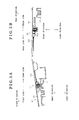
- Fig. 1 is a diagram illustrating a plane structure of, in particular, a roof panel of a vehicle on which a roof apparatus according to a first embodiment disclosed here is mounted;
- Fig. 2 is a cross section view which is taken along line II-II in Fig. 1 and illustrates a cross section structure of the roof apparatus according to the first embodiment disclosed here;
- Fig. 3A is a cross section view which is taken along line IIIA-IIIA in Fig. 1 and illustrates the cross section structure of the roof apparatus according to the first embodiment disclosed here;
- Fig. 3B is a cross section view which is taken along line IIIB-IIIB in Fig. 1 and illustrates the cross section structure of the roof apparatus according to the first embodiment disclosed here;
- Fig. 4 is a cross section view illustrating a cross section structure of a weather strip according to the first embodiment disclosed here;
- Fig. 5 is a diagram illustrating a cross section structure of, in particular, the weather strip that is assembled on a roof panel and on a guide rail of the roof apparatus according to the first embodiment disclosed here;
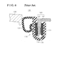
- Fig. 6 is a diagram illustrating a cross section structure of, in particular, a weather strip of a known roof apparatus.
- a roof apparatus 1 an on-vehicle roof apparatus (hereinafter referred to as "a roof apparatus 1 ").
- a front/rear direction of a vehicle is referred to as “a front/rear direction”
- a vertical direction is referred to as "a upper/lower direction”.
- An “inner side” refers to a side that is closer to the center of the roof apparatus 1 in a width direction of the vehicle and an “outer side” refers to a side that is away from the center of the roof apparatus 1 in the width direction of the vehicle.
- the roof apparatus 1 is configured so as to open and close an opening portion A formed at a roof panel 40 of a vehicle on which the roof apparatus 1 is mounted.
- the roof apparatus 1 includes a movable panel 20 for opening and closing the opening portion A by moving in the front/rear direction, and a weather strip 30 which is provided between an opening edge of the roof panel 40 and the movable panel 20 so as to serve as a sealing between the opening edge and the movable panel 20.
- a cross section structure of the roof apparatus 1 will be explained below with reference to Figs. 2 , 3A and 3B .
- the roof panel 40 includes a roof panel body 41 formed into a substantially plane shape and a flange portion 42 formed so as to extend downward from an end portion of the roof panel body 41 located closer to the opening portion A.
- An outer surface 42a of the flange portion 42 that is, the surface facing the movable panel 20, serves as the opening edge of the roof panel 40.
- a guide rail 13 is provided below a right hand end portion of the movable panel 20 and below the roof panel 40 so as to extend in a direction of an opening and closing operation of the movable panel 20, that is, in the front/rear direction of the vehicle. Also, a guide rail mating the above-mentioned guide rail 13 is provided below a left hand end portion of the movable panel 20 and below the roof panel 40 so as to extend in the direction of the opening and closing operation of the movable panel 20, that is, in the front/rear direction of the vehicle.
- the pair of guide rails 13, 13 supports a pair of respective movable members 25, 25 connected to the movable panel 20 so as to drive and move the movable panel 20 for opening and closing the opening portion A in a manner that the pair of the movable members 25, 25 moves relative to the pair of the respective guide rails 13, 13.
- a front housing 11 is provided below a front end portion of the movable panel 20 and below the roof panel 40 so as to extend in a direction perpendicular to the direction of the opening and closing operation of the movable panel 20, that is, in the width direction of the vehicle.
- a rear housing 12 is provided below a rear end portion of the movable panel 20 and below the roof panel 40 so as to extend in the direction perpendicular to the direction of the opening and closing operation of the movable panel 20, that is, in the width direction of the vehicle.
- the guide rails 13, 13, the front housing 11 and the rear housing 12 may be made of metal, resin or other material while maintaining a necessary rigidity.
- the pair of guide rails 13, 13 is formed to be longer than a length from a front end portion to a rear end portion of the flange portion 42 so that the pair of guide rails 13, 13 extends below the entire flange portion 42 at least in the front/rear direction.
- the pair of guide rails 13, 13 is fixedly mounted on the roof panel 40.
- Each of the front housing 11 and the rear housing 12 is formed to be longer than a length from a left hand end portion to a right hand end portion of the flange portion 42 so that each of the front housing 11 and the rear housing 12 extends below the entire flange portion 42 at least in the width direction of the vehicle.
- the front housing 11 and the rear housing 12 are fixedly mounted on the roof panel 40.
- the weather strip 30 is assembled on the flange portion 42 of the roof panel 40 and, as will be explained later, is assembled on the guide rail 13, the front housing 11 and the rear housing 12.
- the guide rail 13, the front housing 11 and the rear housing 12 serve as a supporting member.
- the structure of the weather strip 30 according to this embodiment and an assembly structure of the weather strip 30 are not influenced by an assembly target, i.e. the guide rail 13, the front housing 11 or the rear housing 12, on which the weather strip 30 is assembled.
- the structure of the weather strip 30 and the assembly structure of the weather strip 30 do not need to be modified or changed depending on the assembly target.
- the weather strip 30 and the assembly structure thereof in the case where the weather strip 30 is assembled on the guide rail 13 will be explained in detail as an example with reference to Figs. 4 and 5 .
- the explanation in the case where the weather strip 30 is assembled on the front housing 11 or on the rear housing 12 is omitted.
- a solid line shows the weather strip 30 that is assembled on the guide rail 13 and a chain double-dashed line shows the weather strip 30 before being assembled on the guide rail 13.
- the weather strip 30 includes a base portion 31 and a sealing portion 37 formed integrally with the base portion 31.
- the base portion 31 having a substantially U-shaped cross section includes a base body 32, a core 33, plural protrusions (a first inner-side protrusion 34a, a second inner-side protrusion 34b, and an outer-side protrusion 35) and an upper protrusion 36.
- the first and second inner-side protrusions 34a, 34b serve as inner-side protrusions.
- the sealing portion 37 is connected to a first end of the base body 32 (the upper left end of the base body 32 in Fig. 4 ).
- the core 33 has a substantially U-shaped cross section and is embedded into an inside of the base body 32.
- Each of the plural protrusions protrudes diagonally downward from an inner surface of the base body 32.
- the upper protrusion 36 is formed at a second end of the base body 32 (the upper right end of the base body 32 in Fig. 4 ).
- the sealing portion 37 has a substantially C-shaped cross section and includes a sealing portion body 38 and an extending portion 39. End portions (an upper connecting portion 38a and an inner-side connecting portion 38b) of the sealing portion body 38 are connected to the first end of the base body 32.
- the extending portion 39 is formed at an upper portion of the sealing portion body 38.
- An inner surface of the sealing portion body 38 and an outer surface of the base body 32 define an internal hollow space, and thus the weather strip 30 is formed to have a hollow configuration.
- the base portion 31 of the weather strip 30 is made of a solid rubber, on the contrary, the sealing portion 37 is made of a foam rubber. Additionally the base portion 31 and the sealing portion 37 are made of an identical material. In other words, the base portion 31 and the sealing portion 37, both of which constitute the weather strip 30, are made in a dual molding process.
- ethylene propylene diene monomer rubber (EPDM) is used as a material of the base portion 31 and the sealing portion 37.
- a holding portion 15 which includes an inner-side vertical wall portion 16, an outer-side vertical wall portion 17 and a bottom portion 18, is connected to a guide rail body 14.
- the inner-side vertical wall portion 16 is formed into a substantially plate shape extending upward and is positioned inwardly of the flange portion 42, that is, closer to the center of the roof apparatus 1 relative to the flange portion 42.
- the outer-side vertical wall portion 17 is formed into a substantially plate shape extending upward and is positioned outwardly of the flange portion 42, that is, away from the center of the roof apparatus 1 relative to the flange portion 42.
- the inner-side vertical wall portion 16 and the outer-side vertical wall portion 17 serve as vertical wall portions.
- the bottom portion 18 is positioned below the inner-side and outer-side vertical wall portions 16, 17 so as to extend in a substantially horizontal direction.
- the inner-side vertical wall portion 16 and the outer-side vertical wall portion 17 are connected to end portion of the bottom portion 18, respectively.
- An upper end portion 16a of the inner-side vertical wall portion 16 and an upper end portion 17a of the outer-side vertical wall portion 17 are positioned at a substantially identical height to each other in the vertical direction.
- the upper end portion 16a and the upper end portion 17a serve as a second portion.
- a lower end portion 42c of the flange portion 42 is positioned lower than the upper end portion 16a of the inner-side vertical wall portion 16 and the upper end portion 17a of the outer-side vertical wall portion 17.
- the bottom portion 18 serves as a portion of the guide rail body 14.
- the base portion 31 of the weather strip 30 is positioned between an inner surface of the inner-side vertical wall portion 16 and the flange portion 42, and between an inner surface of the outer-side vertical wall portion 17 and the flange portion 42.
- the inner surfaces of the inner-side and outer-side vertical wall portions 16, 17 and an outer surface of the base portion 31 are in pressure contact with each other.
- the base portion 31 receives the flange portion 42 from an opening of the U-shaped configuration of the base portion 31 so that the base portion 31 accommodates or contains therein the flange portion 42 of the roof panel 40. That is, the flange portion 42 is surrounded by the base portion 31 from below and in the width direction of the vehicle.
- the holding portion 15 holds the base portion 31 of the weather strip 30 in a manner that the base portion 31 is sandwiched by the inner-side vertical wall portion 16 and the outer-side vertical wall portion 17.
- the bottom portion 18 may support the base portion 31 as shown in Fig. 2 .
- a cut-out portion 17c formed on an inner surface of the outer-side vertical wall portion 17 receives therein a projection 32c formed on the outer surface of the base body 32 so as to project from the outer surface of the base body 32 so that the projection 32c is fittedly engaged with the cut-out portion 17c.
- the cut-out portion 17c serves as a receiving member and the projection 32c serves as a fitting member.
- the first and second inner-side protrusions 34a and 34b are formed on the inner surface, which faces the outer surface 42a of the flange portion 42, of the base portion 31 in a manner that the first and second inner-side protrusions 34a and 34b are separated from each other in the vertical direction.
- the first inner-side protrusion 34a formed above the second inner-side protrusion 34b is positioned higher than the upper end portion 16a of the inner-side vertical wall portion 16 and the inner-side protrusion 34b formed below the first inner-side protrusion 34a is positioned lower than the upper end portion 16a.
- the first and second inner-side protrusions 34a and 34b have an identical length to each other in protruding directions. Furthermore, the length of the first and second inner-side protrusions 34a and 34b is shorter than a length of the outer-side protrusion 35 in the protruding directions.
- the outer-side protrusion 35 is formed on the inner surface, which faces an inner surface 42b of the flange portion 42, of the base portion 31.
- the outer-side protrusion 35 is formed to be positioned lower than the first inner-side protrusion 34a, which is positioned higher than the inner-side protrusion 34b, and is formed higher than the inner-side protrusion 34b, which is positioned lower than the first inner-side protrusion 34a.
- the outer-side protrusion 35 is positioned between the first and second inner-side protrusions 34a and 34b in the vertical direction.
- upper surfaces of the first and second inner-side protrusions 34a and 34b are in pressure contact with the outer surface 42a of the flange portion 42.
- An upper surface of the outer-side protrusion 35 is in pressure contact with the inner surface 42b of the flange portion 42.
- the upper protrusion 36 is provided at the second end of the base portion 31, specifically, at the end portion that is positioned between the flange portion 42 and the outer-side vertical wall portion 17.
- An upper surface of the upper protrusion 36 is in pressure contact with an inner surface of the roof panel body 41 as shown by the solid line in Fig. 5 .
- the upper surfaces of the first and second inner-side protrusions 34a and 34b and the upper protrusion 36 refer to the surfaces facing upward before the weather strip 30 is assembled on the flange portion 42 of the roof panel 40.
- the inside of the base portion 31, that is, a clearance formed between the lower end portion 42c of the flange portion 42 and an inner surface facing the lower end portion 42c, of the base portion 31, is filled with a sealing agent.
- the sealing portion 37 is configured so that an outer surface, in particular, a side surface facing the movable panel 20, of the sealing portion body 38 is in contact with the movable panel 20 at least when the movable panel 20 is in a fully closed position.
- the sealing portion body 38 is positioned between the movable panel 20 and the base portion 31.
- the upper connecting portion 38a which is one end portion of the sealing portion body 38, is connected to an inner-side upper end portion 32a of the base body 32.
- the inner-side connecting portion 38b which is the other end portion of the sealing portion body 38, is connected to an inner-side projection 32b protruding from a side surface of the base body 32 toward an upper surface of the upper end portion 16a of the inner-side vertical wall portion 16 so as to be located above the upper surface of the upper end portion 16a of the inner-side vertical wall portion 16 while keeping a clearance therefrom in the vertical direction.
- the sealing portion body 38 is formed in a manner that a lowermost end portion 38c, which is the lowest portion of the sealing portion body 38, is positioned lower than the upper end portion 16a of the inner-side vertical wall portion 16.
- the lowermost end portion 38c serves as a first portion.
- the sealing portion body 38 is in pressure contact with the inner-side vertical wall portion 16 at one portion that is included in an area from the lowermost end portion 38c to the inner-side connecting portion 38b.
- the projection 32c formed on the outer surface of the base body 32 fits in the cut-out portion 17c formed on the inner surface of the outer-side vertical wall portion 17.
- the holding portion 15 holds the base portion 31 of the weather strip 30 in a secure manner.
- the extending portion 39 extends from the upper connecting portion 38a of the sealing portion body 38 outwardly in a manner that an upper surface of the extending portion 39 is in pressure contact with the outer surface 42a of the flange portion 42 as shown by the solid in Fig. 5 .
- the upper surface of the extending portion 39 is referred to as the surface facing upward before the weather strip 30 is assembled on the flange portion 42 of the roof panel 40.
- the sealing portion 37 of the weather strip 30 is positioned between the outer surface 42a of the flange portion 42 of the roof panel 40 and the movable panel 20, and higher than the base portion 31 of the weather strip 30.
- the above-explained roof apparatus 1 is assembled on the roof panel 40 in the following manner.
- the base portion 31 of the weather strip 30 is fitted into the holding portion 15 so that an outer surface of the base portion 31 and an inner surface of the holding portion 15 (the inner-side vertical wall portion 16 and the outer-side vertical wall portion 17) are in pressure contact with each other.
- the inside of the base portion 31 is filled with the sealing agent.
- the flange portion 42 is inserted and fitted into the inside of the base portion 31 from an opening of the base portion 31.
- the weather strip 30 includes the base portion 31 that accommodates therein the flange portion 42 of the roof panel 40.
- the front housing 11, the rear housing 12 and the guide rail 13 which are mounted on the roof panel 40 and support the movable panel 20, are provided with the holding portion 15 that holds the base portion 31 of the weather strip 30.
- the weather strip 30 is assembled in the state where the base portion 31 accommodates therein the flange portion 42 of the roof panel 40 and where the weather strip 30 is held inside the holding portion 15 provided at the front housing 11, the rear housing 12 and the guide rail 13.
- the weather strip 30 is securely held by the holding portion 15 after being assembled. Consequently, reliability of the weather strip 30 may be improved in the case where the weather strip 30 is adapted to the outer surface 42a of the roof panel 40 including the flange 42 that extends from the roof panel body 41 downward in the vertical direction.
- the outer surface of the base portion 31 of the weather strip 30 is in pressure contact with the inner surface of the holding portion 15 (the inner-side vertical wall portion 16 and the outer-side vertical wall portion 17). According to the above described structure, the weather strip 30 is securely held by the holding portion 15 after being assembled. In addition, the outer surface of the base portion 31 of the weather strip 30 is in pressure contact with the inner surface of the holding portion 15, and thus a sealing effect between the outer surface of the base portion 31 and the inner surface of the holding portion 15 may be improved.
- the protrusions (the first inner-side protrusion 34a, the second inner-side protrusion 34b, and the outer-side protrusion 35), each of which protrudes toward the flange portion 42 of the roof panel 40 are formed on the inner surface of the base portion 31 of the weather strip 30 so as to be in contact with the flange portion 42.
- a sealing effect between the inner surface of the base portion 31 and the flange portion 42 may be improved by maintaining the protrusions 34a, 34b and 35 in contact (pressure contact) with the flange portion 42 of the roof panel 40.
- the upper protrusion 36 protruding toward the inner surface of the roof panel body 41 so as to be in contact with the inner surface of the roof panel 41 is provided at the base portion 31 of the weather strip 30. According to the above described structure, a sealing effect between the base portion 31 and the inner surface of the roof panel body 41 may be improved by maintaining the upper protrusion 36 in contact (pressure contact) with the inner surface of the roof panel body 41.
- the weather strip 30 includes the sealing portion 37 having the hollow configuration which is formed integrally with the base portion 31 and is in contact with the movable panel 20 at least when the movable panel 20 is in the fully closed position.
- the lowermost end portion 38c which is the lowest portion of the sealing portion 37 in the vertical direction, is positioned lower than the upper end portion 16a, which is the highest portion of the inner-side vertical wall portion 16 in the vertical direction.
- the upper end portion 16a which is the highest portion of the holding portion 15 in the vertical direction, is conveniently positioned at a higher position relative to the base portion 31 of the weather strip 30 related to the roof apparatus 1 including the weather strip 30 provided with the base portion 31 and the sealing portion 37 having the hollow configuration.
- the weather strip 30 is securely held by the holding portion 15.
- the sealing portion 37 of the weather strip 30 includes the sealing portion body 38 positioned between the movable panel 20 and the base portion 31, and the extending portion 39 extending from the sealing portion body 38 so as to be in contact with the flange portion 42.
- the extending portion 39 is positioned higher than the base portion 31 in the vertical direction between the movable panel 20 and the flange portion 42.
- the guide rail 13 is adapted as the supporting member at which the holding portion 15 is provided.
- the guide rail 13 extends in the direction of the opening and closing operation of the movable panel 20, that is, in the front/rear direction of the vehicle so as to support the movable member 25 which drives and moves the movable panel 20 for opening and closing the opening portion A.
- the holding portion 15 holding the weather strip 30 that extends in the front/rear direction of the vehicle is readily provided by partly changing structures of the existing guide rails 13.
- the front housing 11 and the rear housing 12 are adapted as the supporting members at which the holding portion 15 is provided.
- Each of the front housing 11 and the rear housing 12 extends in the direction perpendicular to the direction of the opening and closing operation of the movable panel 20 (the width direction of the vehicle) and connects the pair of guide rails 13, 13 with each other.
- the holding portion 15 holding the weather strip 30 that extends in the width direction of the vehicle is readily provided by partly changing structures of the existing front housing 11 and the rear housing 12.
- a sealing effect between the movable panel 20 and the inner-side vertical wall portion 16 may be enhanced by means of the sealing portion body 38.
- the sealing effect between the base portion 31 and the flange portion 42 may be enhanced by means of the extending portion 39, the first and second inner-side protrusions 34a and 34b, the sealing agent and the outer-side protrusion 35.
- the sealing effect between the base portion 31 and the inner surface of the roof panel body 41 may be enhanced by means of the upper protrusion 36.
- the sealing effect between the inner surface of the holding portion 15 and the base portion 31 may be enhanced because the holding portion 15 and the base portion 31 are in pressure contact with each other.
- the inside of the base portion 31 is filled with the sealing agent in the state where the weather strip 30 is assembled on the guide rail 13.
- the flange portion 42 is inserted and fitted into the inside of the base portion 31 from the opening of the base portion 31.
- the roof apparatus 1 is assembled on the roof panel 40. This allows the roof apparatus 1 to be shipped in the state where the weather strip 30 is assembled on, for example, any one of the guide rail 13, the front housing 11, the rear housing 12 or the like. Consequently, an assembly time is reduced compared to a manufacturing process where the weather strip 30 alone is assembled on the roof apparatus 1 in a production line of the vehicle, thereby simplifying the manufacturing process of the vehicle.
- the first and second inner-side protrusions 34a and 34b are arranged while being apart from each other in the vertical direction. Furthermore, in this embodiment, the number of the inner-side protrusions 34a and 34b is set to be greater than the number of the outer-side protrusion 35 relative to the vertical direction. The length of the first and second inner-side protrusions 34a and 34b is shorter than the length of the outer-side protrusion 35 in the protruding direction. According to the above described structure, a degree of deflection of the first and second inner-side protrusions 34a and 34b becomes smaller than that of the outer-side protrusion 35. This stabilizes a posture of the sealing portion 37 relative to the flange portion 42, thereby properly improving a sealing performance of the weather strip 30.
- a smaller area of the weather strip 30 is exposed between the roof panel 40 and the movable panel 20 compared to a case that the number of the first and second inner-side protrusions 34a and 34b is set to be equal to or less than the number of the outer-side protrusion 35 relative to the vertical direction or a case that the length of the first and second inner-side protrusions 34a and 34b is formed to be longer than the length of the outer-side protrusion 35 in the protruding direction.
- This may contribute to improvement in a design, that is, an esthetic appearance of the roof apparatus 1.
- the roof apparatus 1 includes no water discharge path for discharging the water that is entering or has entered into the interior of the vehicle from the gap between the movable panel 20 and the roof panel 40.
- the structure of the roof apparatus 1 is not limited thereto and the water discharge path may be provided.
- the holding portion 15 that holds the weather strip 30 is formed by partly changing the structure of the front housing 11, the rear housing 12 and the guide rail 13, however, other structures than the front housing 11, the housing 12 or the guide rail 13 may be used as the supporting member as long as the supporting member is mounted on the roof panel 40 and supports the moveable panel 20 directly or indirectly.
- the sealing portion 37 desirably includes the sealing portion body 38 which is positioned between the movable panel 20 and the base portion 31, and the extending portion 39 extending from the sealing portion body 38 so as to be positioned between the movable panel 20 and the flange portion 42 and to be in contact with the flange portion 42 at the higher position than the base portion 31 in the vertical direction in order to avoid the deterioration of the appearance of the weather strip 30, and eventually, the appearance of the roof apparatus.
- the extending portion 39 may be omitted from the sealing portion 37 in case that no consideration of the appearance of the roof apparatus 1 is necessary.
- the lowermost end portion 38c which is the lowest portion of the sealing portion 37, is desirably positioned lower than the upper end portion 16a, which is the highest portion of the inner-side vertical wall portion 16 in the vertical direction, in view that the upper end portion 16a, which is the highest portion of the holding portion 15 (the inner-side vertical wall portion 16), is conveniently positioned at the high position relative to the base portion 31.
- the configuration of the sealing portion 37 is not limited thereto.
- the lowermost end portion 38c of the sealing portion body 38 may be positioned higher than the upper end portion 16a of the inner-side vertical wall portion 16 as long as the weather strip 30 is surely held in place by means of other configurations than the inner-side vertical wall portion 16.
- the upper protrusion 36 is desirably provided at the base portion 31 in order to improve the sealing effect between the base portion 31 and the inner surface of the roof panel body 41.
- the upper protrusion 36 may be omitted from the weather strip 30 in case that the entry of the water into the interior of the vehicle is properly regulated by means of, for example, the first and second inner-side protrusions 34a, 34b or the outer-side protrusion 35.
- two outer-side protrusions may be provided in a manner similar to the forming of the first and second inner-side protrusions 34a and 34b as explained in this embodiment.
- three or more outer-side protrusions may be provided.
- one inner-side protrusion may be provided in a manner similar to the forming of the outer-side protrusion 35 as explained in this embodiment.
- three or more inner-side protrusions may be provided.
- the length of the outer-side protrusion 35 may be set to be equal to or shorter than the length of the first and second inner-side protrusions 34a and 34b.
- the protrusions are desirably formed on the inner surface of the base portion 31 so as to protrude toward the flange portion 42 of the roof panel 40 and to be in contact with the flange portion 42 in order to improve the sealing effect between the inner surface of the base portion 31 and the flange portion 42.
- the roof panel 1 according to this embodiment is not limited thereto.
- the protrusions formed on the inner surface of the base portion 31 may be omitted and the inner surface of the base portion 31 may be formed to be in pressure contact with the flange portion 42 as long as the sealing effect is ensured between the inner surface of the base portion 31 and the flange portion 42 simply by providing the sealing agent therebetween.
- the first and second inner-side protrusions 34a and 34b may be omitted, or only the outer-side protrusion 35 may be omitted.
- the outer surface of the base portion 31 of the weather strip 30 is in pressure contact with the inner surface, which faces the outer surface of the base portion 31, of the holding portion 15 (the inner-side vertical wall portion 16 and the outer-side vertical wall portion 17) in order to enhance the sealing effect between the outer surface of the base portion 31 and the inner surface of the holding portion 15.
- the base portion 31 and the inner surface of the holding portion 15 are not necessarily to be in pressure contact with each other as long as the sealing portion 37 appropriately blocks the waterfrom entering into the interior of the vehicle from the gap between the movable panel 20 and the roof panel 40 into the interior of the vehicle, in other words, in case that a necessity of the sealing effect between the outer surface of the base portion 31 and the inner surface of the holding portion 15 is not high.
- a size or a length of the inner-side vertical wall portion 16 and the outer-side vertical wall portion 17 in the vertical direction is set to be the same level to each other.
- the size of either one of the inner-side vertical wall portion 16 and the outer-side vertical wall portion 17 in the vertical direction may be larger than that of the other one of the inner-side vertical wall portion 16 and the outer-side vertical wall portion 17.
- the inner-side vertical wall portion 16, the outer-side vertical wall portion 17, the base portion 31 of the weather strip 31 and the flange portion 42 are located at positions so as to substantially correspond to each other in the vertical direction, that is, the inner-side vertical wall portion 16, the outer-side vertical wall portion 17, the base portion 31 of the weather strip 31 and the flange portion 42 are overlapping with one another in the vertical direction.
- the configuration of the roof apparatus 1 according to this embodiment is not limited thereto.
- the roof apparatus 1 may include a configuration where the inner-side and outer-side vertical wall portions 16, 17 and the base portion 31 of the weather strip 30 are overlapping with each other at a position in the vertical direction by forming either one of the inner-side vertical wall portion 16 and the outer-side vertical wall portion 17 to be smaller than the other one in the size in the vertical direction while, the inner-side and outer-side vertical wall portions 16, 17 and the flange portion 42 do not overlap with each other.
- the holding portion 15 includes the inner-side vertical wall portion 16 and the outer-side vertical wall portion 17, however, the holding portion 15 of this embodiment is not limited thereto.
- the holding portion may include either one of the inner-side vertical wall portion 16 and the outer-side vertical wall portion 17.
- any suitable member mounted on the roof panel 40 for supporting the movable panel 20 may be adapted as the supporting member.
- Any portion provided at the supporting member for holding the base portion 31 of the weather strip 30 may be adapted as the holding portion.
Landscapes
- Engineering & Computer Science (AREA)
- Mechanical Engineering (AREA)
- Seal Device For Vehicle (AREA)
Abstract
Description
- This disclosure generally relates to a roof apparatus.
- A known roof apparatus is disclosed in JPH7-117582A (hereinafter referred to as Patent reference 1).
- Illustrated in
Fig. 6 is a configuration example of the known roof apparatus according to thePatent reference 1. As shown inFig. 6 , theroof apparatus 101 disclosed inPatent reference 1 includes amovable panel 120 for opening and closing an opening portion of aroof panel 140, and aweather strip 130 provided between an opening edge of theroof panel 140 and themovable panel 120 so as to serve as a sealing between the opening edge and themovable panel 120. The opening edge of theroof panel 140 is defined by an outer surface (a surface facing the left side inFig. 6 ) of aflange portion 142 that extends vertically downward from aroof panel body 141. Theweather strip 130 includes atrim portion 131 and aseal portion 137. Thetrim portion 131 has a substantially U-shaped cross section and includes acore 133 embedded into an inside of thetrim portion 131. Theseal portion 137 having a hollow configuration so as to be expanded from an outer surface of thetrim portion 131. In order to assemble theweather strip 131 on theroof panel 140, thetrim portion 131 is clamped by using a jig so that an opening of thetrim portion 131 is narrowed, in a state where theflange portion 142 is accommodated inside of thetrim portion 131. According toPatent reference 1, asponge member 150 is provided at an inner surface of thetrim portion 131 and an inner surface of thesponge member 150 is in a pressure contact with theflange portion 141. - According to the
known roof apparatus 101 disclosed inPatent reference 1, the inner surface of thetrim portion 131, more specifically, thesponge member 150, press-fittingly contacts with theflange portion 142 by clamping thetrim portion 131 of theweather strip 130, and thus theweather strip 130 is assembled on theflange portion 142. However, once the opening of thetrim portion 131 is enlarged due to an application of some force or due to other causes, an assembly state of theweather strip 130 may become unstable, which may decrease a sealing performance of theweather strip 130. Therefore, there remains room for improving a reliability of the weather strip of the known roof apparatus disclosedPatent reference 1 - A need thus exists for a roof apparatus in which an opening edge of the roof panel includes a flange portion extending vertically downward from a roof panel body and which enhances a reliability of a weather strip.
- According to an aspect of this disclosure, a roof apparatus includes a movable panel for opening and closing an opening portion adapted to be provided on a roof panel, and a weather strip disposed between an opening edge of the roof panel and the movable panel so as to serve as a sealing between the opening edge and the movable panel. The opening edge of the roof panel includes a flange portion formed to extend vertically downward from a roof panel body of the roof panel. The weather strip includes a base portion accommodating the flange portion of the roof panel inside the base portion. A supporting member mounted on the roof panel and supporting the movable panel includes a holding portion holding the base portion of the weather strip.
- According to the above described structure, the weather strip is assembled in a state where the base portion accommodates therein the flange portion of the roof panel and that the weather strip is held inside the holding portion provided at the supporting member. Thus, unlike a structure where for example the flange portion of the roof panel is simply sandwiched by the base portion, the weather strip is securely held by the holding portion after being assembled. Consequently, a reliability of the weather strip, which is provided to the roof apparatus whose opening edge of the roof panel includes the flange extending from the roof panel body downward in the vertical direction, may be enhanced.
- According to another aspect of this disclosure, the holding portion includes at least one of an inner-side vertical wall portion extending in a vertical direction and positioned inward toward the roof apparatus relative to the flange portion and an outer-side vertical wall portion extending in the vertical direction and positioned outward toward the roof apparatus relative to the flange portion. The base portion of the weather strip is held between the flange portion and at least one of the inner-side vertical wall portion and the outer-side vertical wall portion in a manner that the weather strip is sandwiched between the flange portion and at least one of the inner-side vertical wall portion and the outer-side vertical wall portion.
- According to the above described structure, the base portion is held by the flange portion and at least one of the inner-side vertical wall portion and the outer-side vertical wall portion. Thus, the weather strip is even more securely held after being assembled, thereby enhancing the reliability of the weather strip. The holding portion desirably includes the inner-side vertical wall portion and the outer-side vertical wall portion. This allows the supporting member and the weather strip to be assembled on the roof panel in a state where the inner-side vertical wall portion and the outer-side vertical wall portion, both of which constitute the supporting member, hold therebetween the base portion of the weather strip. Consequently, an assemblability or an assembly performance may be improved compared to the manufacturing process where the weather strip is assembled independently from the supporting member on the roof apparatus in a production line of the vehicle, thereby simplifying the manufacturing process of the vehicle.
- According to a further aspect of this disclosure, an outer surface of the base portion of the weather strip is in pressure contact with the holding portion which faces the outer surface of the base portion of the weather strip.
- According to the above described structure, the weather strip is even more securely held by the holding portion after being assembled. In addition, the outer surface of the base portion of the weather strip is in pressure contact with the inner surface of the holding portion opposing the outer surface of the base portion, and thus a sealing effect between the outer surface of the base portion and the holding portion may be improved.
- According to a further aspect of this disclosure, a protrusion is formed at an inner surface of the base portion of the weather strip. The protrusion protrudes toward the flange portion of the roof panel so as to be in contact with the flange portion.
- According to the above described structure, the protrusion formed on the base portion of the weather strip is maintained in pressure contact with the flange portion of the roof panel, and thus a sealing effect between the inner surface of the base portion and the flange portion may be enhanced.
- According to a further aspect of this disclosure, the weather strip includes a sealing portion formed into a hollow configuration and formed integrally with the base portion so as to be in contact with the movable panel at least when the movable panel is in a fully closed position, and the protrusion includes an inner-side protrusion positioned inwardly of the roof apparatus relative to the flange portion and an outer-side protrusion positioned outwardly of the roof apparatus relative to the flange portion.
- According to the above described structure, the inner-side protrusion and the outer-side protrusion are formed on the inner surface of the base portion, and thus the sealing effect between the inner surface of the base portion and the flange portion may be further improved when comparing to the structure where either one of the inner-side protrusion and the outer-side protrusion is formed.
- According to a further aspect of this disclosure, the inner-side protrusion includes a plurality of inner-side protrusions formed to be in parallel with each other in the vertical direction, and a number of the plurality of the inner-side protrusions relative to the vertical direction is greater than a number of the outer-side protrusion relative to the vertical direction.
- According to the above described structure, the degree of deflection of the inner-side protrusions may become smaller than that of the outer-side protrusion. This stabilizes the posture of the sealing portion relative to the flange portion, thereby properly improving the sealing performance of the weather strip. In addition, a smaller area of the weather strip is exposed between the roof panel and the movable panel compared to a case that the number of the inner-side protrusions is equal to or less than the number of the outer-side protrusion relative to the vertical. This contributes to improvement in a design, that is, an esthetic appearance of the roof apparatus.
- According to a further aspect of this disclosure, a length of the inner-side protrusion in a direction in which the inner-side protrusion protrudes is formed to be shorter than a length of the outer-side protrusion in a direction in which the outer-side protrusion protrudes.
- According to the above described structure, the degree of deflection of the inner-side protrusions may become smaller than that of the outer-side protrusion. This stabilizes the posture of the sealing portion relative to the flange portion, thereby properly improving the sealing performance of the weather strip. In addition, the smaller area of the weather strip is exposed between the roof panel and the movable panel compared to a case that the length of the inner-side protrusions is shorter than the length of the outer-side protrusion in the protruding direction. This contributes to improvement in the design, that is, the esthetic appearance of the roof apparatus.
- According to a further aspect of this disclosure, a protrusion is formed at the base portion of the weather strip, and the protrusion formed at the base portion of the weather strip protrudes toward an inner surface of the roof panel body so as to be in contact with the inner surface of the roof panel body.
- According to the above described structure, the sealing effect between the base portion of the weather strip and the inner surface of the roof panel body may be improved by maintaining the protrusion formed at the base portion in contact with the inner surface of the roof panel body.
- In case that the roof panel body is constituted by a single panel, the roof panel body serves as the panel. On the other hand, in case that the roof panel body is constituted by plural panels overlaid on each other or in case that the roof panel body includes a reinforcement member in addition to the panel, all these panels and the reinforcement member serve as the roof panel body.
- According to a further aspect of this disclosure, the weather strip includes a sealing portion formed into a hollow configuration and formed integrally with the base portion so as to be in contact with the movable panel at least when the movable panel is in the fully closed position, and the sealing portion is provided in a manner that a first portion of the sealing portion, which is positioned at a lowest position in the sealing portion in the vertical direction, is located lower than a second portion of the holding portion of the supporting member, which is positioned at a highest position relative to the holding portion in the vertical direction, between the sealing portion and the base portion.
- According to the above described structure, in case that the roof apparatus includes the weather strip provided with the base portion and the sealing portion formed into the hollow configuration, the second portion of the holding portion is conveniently positioned higher relative to the base portion. Thus, the weather strip is even more securely held by the holding portion.
- According to a further aspect of this disclosure, the sealing portion of the weather strip includes a sealing portion body positioned between the movable panel and the base portion, and an extending portion extending from the sealing portion body and being positioned higher than the base portion in the vertical direction between the movable panel and the flange portion so as to be in contact with the flange portion.
- According to the above described structure, when the roof apparatus is viewed from the outside of the roof apparatus, only the sealing portion is visible between the flange portion of the roof panel and the movable panel. Therefore, deterioration of the appearance of the weather strip, and eventually, the appearance of the roof apparatus may be avoided even in case that the base portion and the sealing portion, both of which constitute the weather strip, are made in the dual molding process so as to have different colors between the base portion and the sealing portion.
- According to a further aspect of this disclosure, the roof apparatus includes a guide rail extending in a direction in which the movable panel moves to open and close the opening portion of the roof panel and supporting a movable member for moving the movable panel in a manner that the movable member is movable relative to the guide rail, where the supporting member includes the guide rail.
- According to the above described structure, the holding portion holding the weather strip that extends in the direction of the opening and closing operation of the movable panel, may be readily achieved by partly changing a structure of the existing guide rail.
- According to a further aspect of this disclosure, the roof apparatus includes a pair of guide rails extending in the direction in which the movable panel moves to open and close the opening portion of the roof panel and supporting the movable member for moving the movable panel in a manner that the movable member is movable relative to the pair of the guide rails and a connecting member extending in a direction perpendicular to the direction in which the movable panel moves and connecting the pair of guide rails to each other, where the supporting member includes the connecting member.
- According to the above described structure, the holding portion holding the weather strip that extends in the perpendicular direction to the direction of the opening and closing operation of the movable panel, may be readily achieved by partly changing structure of the existing supporting member.
- According to a further aspect of this disclosure, a fitting member is formed on one of the weather strip and the holding portion and a receiving member is formed on the other one of the weather strip and the holding portion, and the fitting member is fittedly engaged with the receiving member.
- According to the above described structure, the fitting member is fittedly engaged with the receiving member, and thus the base portion of the weather strip is securely held by the holding portion.
- According to the above described structure, the roof apparatus, in which the opening edge of the roof panel includes the flange portion extending vertically downward from the roof panel body and which enhances the reliability of the weather strip, may be provided.
- The foregoing and additional features and characteristics of this disclosure will become more apparent from the following detailed description considered with the reference to the accompanying drawings, wherein:
-
Fig. 1 is a diagram illustrating a plane structure of, in particular, a roof panel of a vehicle on which a roof apparatus according to a first embodiment disclosed here is mounted; -
Fig. 2 is a cross section view which is taken along line II-II inFig. 1 and illustrates a cross section structure of the roof apparatus according to the first embodiment disclosed here; -
Fig. 3A is a cross section view which is taken along line IIIA-IIIA inFig. 1 and illustrates the cross section structure of the roof apparatus according to the first embodiment disclosed here; -
Fig. 3B is a cross section view which is taken along line IIIB-IIIB inFig. 1 and illustrates the cross section structure of the roof apparatus according to the first embodiment disclosed here; -
Fig. 4 is a cross section view illustrating a cross section structure of a weather strip according to the first embodiment disclosed here; -
Fig. 5 is a diagram illustrating a cross section structure of, in particular, the weather strip that is assembled on a roof panel and on a guide rail of the roof apparatus according to the first embodiment disclosed here; and -
Fig. 6 is a diagram illustrating a cross section structure of, in particular, a weather strip of a known roof apparatus. - A first embodiment of a roof apparatus related to this disclosure will be explained with reference to illustrations of
Figs. 1 to 5 of the attached drawings. In this embodiment, the roof apparatus is adapted as an on-vehicle roof apparatus (hereinafter referred to as "aroof apparatus 1 "). Hereinafter, a front/rear direction of a vehicle is referred to as "a front/rear direction" and a vertical direction is referred to as "a upper/lower direction". An "inner side" refers to a side that is closer to the center of theroof apparatus 1 in a width direction of the vehicle and an "outer side" refers to a side that is away from the center of theroof apparatus 1 in the width direction of the vehicle. - As shown in
Fig. 1 , theroof apparatus 1 is configured so as to open and close an opening portion A formed at aroof panel 40 of a vehicle on which theroof apparatus 1 is mounted. Theroof apparatus 1 includes amovable panel 20 for opening and closing the opening portion A by moving in the front/rear direction, and aweather strip 30 which is provided between an opening edge of theroof panel 40 and themovable panel 20 so as to serve as a sealing between the opening edge and themovable panel 20. - A cross section structure of the
roof apparatus 1 will be explained below with reference toFigs. 2 ,3A and 3B . - As shown in
Figs. 2 ,3A and 3B , theroof panel 40 includes aroof panel body 41 formed into a substantially plane shape and aflange portion 42 formed so as to extend downward from an end portion of theroof panel body 41 located closer to the opening portion A. Anouter surface 42a of theflange portion 42, that is, the surface facing themovable panel 20, serves as the opening edge of theroof panel 40. - As shown in
Fig. 2 , aguide rail 13 is provided below a right hand end portion of themovable panel 20 and below theroof panel 40 so as to extend in a direction of an opening and closing operation of themovable panel 20, that is, in the front/rear direction of the vehicle. Also, a guide rail mating the above-mentionedguide rail 13 is provided below a left hand end portion of themovable panel 20 and below theroof panel 40 so as to extend in the direction of the opening and closing operation of themovable panel 20, that is, in the front/rear direction of the vehicle. The pair ofguide rails movable members movable panel 20 so as to drive and move themovable panel 20 for opening and closing the opening portion A in a manner that the pair of themovable members respective guide rails - As shown in
Fig. 3A , a front housing 11 is provided below a front end portion of themovable panel 20 and below theroof panel 40 so as to extend in a direction perpendicular to the direction of the opening and closing operation of themovable panel 20, that is, in the width direction of the vehicle. - As shown in
Fig. 3B , arear housing 12 is provided below a rear end portion of themovable panel 20 and below theroof panel 40 so as to extend in the direction perpendicular to the direction of the opening and closing operation of themovable panel 20, that is, in the width direction of the vehicle. The guide rails 13, 13, the front housing 11 and therear housing 12 may be made of metal, resin or other material while maintaining a necessary rigidity. - The pair of
guide rails flange portion 42 so that the pair ofguide rails entire flange portion 42 at least in the front/rear direction. The pair ofguide rails roof panel 40. - Each of the front housing 11 and the
rear housing 12 is formed to be longer than a length from a left hand end portion to a right hand end portion of theflange portion 42 so that each of the front housing 11 and therear housing 12 extends below theentire flange portion 42 at least in the width direction of the vehicle. The front housing 11 and therear housing 12 are fixedly mounted on theroof panel 40. - As shown in
Figs. 2 ,3A and 3B , theweather strip 30 is assembled on theflange portion 42 of theroof panel 40 and, as will be explained later, is assembled on theguide rail 13, the front housing 11 and therear housing 12. - The
guide rail 13, the front housing 11 and therear housing 12 serve as a supporting member. The structure of theweather strip 30 according to this embodiment and an assembly structure of theweather strip 30 are not influenced by an assembly target, i.e. theguide rail 13, the front housing 11 or therear housing 12, on which theweather strip 30 is assembled. In other words, the structure of theweather strip 30 and the assembly structure of theweather strip 30 do not need to be modified or changed depending on the assembly target. - The
weather strip 30 and the assembly structure thereof in the case where theweather strip 30 is assembled on theguide rail 13 will be explained in detail as an example with reference toFigs. 4 and5 . The explanation in the case where theweather strip 30 is assembled on the front housing 11 or on therear housing 12 is omitted. - In
Fig. 5 , a solid line shows theweather strip 30 that is assembled on theguide rail 13 and a chain double-dashed line shows theweather strip 30 before being assembled on theguide rail 13. - As shown in
Fig. 4 , theweather strip 30 includes abase portion 31 and a sealingportion 37 formed integrally with thebase portion 31. Thebase portion 31 having a substantially U-shaped cross section includes abase body 32, acore 33, plural protrusions (a first inner-side protrusion 34a, a second inner-side protrusion 34b, and an outer-side protrusion 35) and anupper protrusion 36. The first and second inner-side protrusions portion 37 is connected to a first end of the base body 32 (the upper left end of thebase body 32 inFig. 4 ). Thecore 33 has a substantially U-shaped cross section and is embedded into an inside of thebase body 32. Each of the plural protrusions (the first and second inner-side protrusions base body 32. Theupper protrusion 36 is formed at a second end of the base body 32 (the upper right end of thebase body 32 inFig. 4 ). - The sealing
portion 37 has a substantially C-shaped cross section and includes a sealingportion body 38 and an extendingportion 39. End portions (an upper connectingportion 38a and an inner-side connecting portion 38b) of the sealingportion body 38 are connected to the first end of thebase body 32. The extendingportion 39 is formed at an upper portion of the sealingportion body 38. An inner surface of the sealingportion body 38 and an outer surface of thebase body 32 define an internal hollow space, and thus theweather strip 30 is formed to have a hollow configuration. - In this embodiment, the
base portion 31 of theweather strip 30 is made of a solid rubber, on the contrary, the sealingportion 37 is made of a foam rubber. Additionally thebase portion 31 and the sealingportion 37 are made of an identical material. In other words, thebase portion 31 and the sealingportion 37, both of which constitute theweather strip 30, are made in a dual molding process. In this embodiment, ethylene propylene diene monomer rubber (EPDM) is used as a material of thebase portion 31 and the sealingportion 37. - As shown in
Fig. 5 , a holdingportion 15, which includes an inner-sidevertical wall portion 16, an outer-sidevertical wall portion 17 and abottom portion 18, is connected to aguide rail body 14. The inner-sidevertical wall portion 16 is formed into a substantially plate shape extending upward and is positioned inwardly of theflange portion 42, that is, closer to the center of theroof apparatus 1 relative to theflange portion 42. The outer-sidevertical wall portion 17 is formed into a substantially plate shape extending upward and is positioned outwardly of theflange portion 42, that is, away from the center of theroof apparatus 1 relative to theflange portion 42. The inner-sidevertical wall portion 16 and the outer-sidevertical wall portion 17 serve as vertical wall portions. Thebottom portion 18 is positioned below the inner-side and outer-sidevertical wall portions vertical wall portion 16 and the outer-sidevertical wall portion 17 are connected to end portion of thebottom portion 18, respectively. Anupper end portion 16a of the inner-sidevertical wall portion 16 and anupper end portion 17a of the outer-sidevertical wall portion 17 are positioned at a substantially identical height to each other in the vertical direction. Theupper end portion 16a and theupper end portion 17a serve as a second portion. Alower end portion 42c of theflange portion 42 is positioned lower than theupper end portion 16a of the inner-sidevertical wall portion 16 and theupper end portion 17a of the outer-sidevertical wall portion 17. Thebottom portion 18 serves as a portion of theguide rail body 14. - The
base portion 31 of theweather strip 30 is positioned between an inner surface of the inner-sidevertical wall portion 16 and theflange portion 42, and between an inner surface of the outer-sidevertical wall portion 17 and theflange portion 42. The inner surfaces of the inner-side and outer-sidevertical wall portions base portion 31 are in pressure contact with each other. In other words, thebase portion 31 receives theflange portion 42 from an opening of the U-shaped configuration of thebase portion 31 so that thebase portion 31 accommodates or contains therein theflange portion 42 of theroof panel 40. That is, theflange portion 42 is surrounded by thebase portion 31 from below and in the width direction of the vehicle. At the same time, the holdingportion 15 holds thebase portion 31 of theweather strip 30 in a manner that thebase portion 31 is sandwiched by the inner-sidevertical wall portion 16 and the outer-sidevertical wall portion 17. Thebottom portion 18 may support thebase portion 31 as shown inFig. 2 . - A cut-out
portion 17c formed on an inner surface of the outer-sidevertical wall portion 17 receives therein aprojection 32c formed on the outer surface of thebase body 32 so as to project from the outer surface of thebase body 32 so that theprojection 32c is fittedly engaged with the cut-outportion 17c. The cut-outportion 17c serves as a receiving member and theprojection 32c serves as a fitting member. The first and second inner-side protrusions outer surface 42a of theflange portion 42, of thebase portion 31 in a manner that the first and second inner-side protrusions side protrusion 34a formed above the second inner-side protrusion 34b is positioned higher than theupper end portion 16a of the inner-sidevertical wall portion 16 and the inner-side protrusion 34b formed below the first inner-side protrusion 34a is positioned lower than theupper end portion 16a. The first and second inner-side protrusions side protrusions side protrusion 35 in the protruding directions. The outer-side protrusion 35 is formed on the inner surface, which faces aninner surface 42b of theflange portion 42, of thebase portion 31. Specifically, the outer-side protrusion 35 is formed to be positioned lower than the first inner-side protrusion 34a, which is positioned higher than the inner-side protrusion 34b, and is formed higher than the inner-side protrusion 34b, which is positioned lower than the first inner-side protrusion 34a. In other words, the outer-side protrusion 35 is positioned between the first and second inner-side protrusions Fig. 5 , upper surfaces of the first and second inner-side protrusions outer surface 42a of theflange portion 42. An upper surface of the outer-side protrusion 35 is in pressure contact with theinner surface 42b of theflange portion 42. Theupper protrusion 36 is provided at the second end of thebase portion 31, specifically, at the end portion that is positioned between theflange portion 42 and the outer-sidevertical wall portion 17. An upper surface of theupper protrusion 36 is in pressure contact with an inner surface of theroof panel body 41 as shown by the solid line inFig. 5 . The upper surfaces of the first and second inner-side protrusions upper protrusion 36 refer to the surfaces facing upward before theweather strip 30 is assembled on theflange portion 42 of theroof panel 40. - The inside of the
base portion 31, that is, a clearance formed between thelower end portion 42c of theflange portion 42 and an inner surface facing thelower end portion 42c, of thebase portion 31, is filled with a sealing agent. The sealingportion 37 is configured so that an outer surface, in particular, a side surface facing themovable panel 20, of the sealingportion body 38 is in contact with themovable panel 20 at least when themovable panel 20 is in a fully closed position. - The sealing
portion body 38 is positioned between themovable panel 20 and thebase portion 31. The upper connectingportion 38a, which is one end portion of the sealingportion body 38, is connected to an inner-sideupper end portion 32a of thebase body 32. The inner-side connecting portion 38b, which is the other end portion of the sealingportion body 38, is connected to an inner-side projection 32b protruding from a side surface of thebase body 32 toward an upper surface of theupper end portion 16a of the inner-sidevertical wall portion 16 so as to be located above the upper surface of theupper end portion 16a of the inner-sidevertical wall portion 16 while keeping a clearance therefrom in the vertical direction. As shown by the solid line and the chain double-dashed line inFig. 5 , the sealingportion body 38 is formed in a manner that alowermost end portion 38c, which is the lowest portion of the sealingportion body 38, is positioned lower than theupper end portion 16a of the inner-sidevertical wall portion 16. Thelowermost end portion 38c serves as a first portion. As shown by the full line inFig. 5 , the sealingportion body 38 is in pressure contact with the inner-sidevertical wall portion 16 at one portion that is included in an area from thelowermost end portion 38c to the inner-side connecting portion 38b. As described before, theprojection 32c formed on the outer surface of thebase body 32 fits in the cut-outportion 17c formed on the inner surface of the outer-sidevertical wall portion 17. Thus, the holdingportion 15 holds thebase portion 31 of theweather strip 30 in a secure manner. - The extending
portion 39 extends from the upper connectingportion 38a of the sealingportion body 38 outwardly in a manner that an upper surface of the extendingportion 39 is in pressure contact with theouter surface 42a of theflange portion 42 as shown by the solid inFig. 5 . The upper surface of the extendingportion 39 is referred to as the surface facing upward before theweather strip 30 is assembled on theflange portion 42 of theroof panel 40. Thus, the sealingportion 37 of theweather strip 30 is positioned between theouter surface 42a of theflange portion 42 of theroof panel 40 and themovable panel 20, and higher than thebase portion 31 of theweather strip 30. - The above-explained
roof apparatus 1 is assembled on theroof panel 40 in the following manner. First, thebase portion 31 of theweather strip 30 is fitted into the holdingportion 15 so that an outer surface of thebase portion 31 and an inner surface of the holding portion 15 (the inner-sidevertical wall portion 16 and the outer-side vertical wall portion 17) are in pressure contact with each other. In the state where theweather strip 30 is assembled on the front housing 11, therear housing 12 and theguide rail 13, the inside of thebase portion 31 is filled with the sealing agent. Then, theflange portion 42 is inserted and fitted into the inside of thebase portion 31 from an opening of thebase portion 31. - As explained above, according to this embodiment, the following advantages and merits may be obtained. According to this embodiment, the
weather strip 30 includes thebase portion 31 that accommodates therein theflange portion 42 of theroof panel 40. The front housing 11, therear housing 12 and theguide rail 13 which are mounted on theroof panel 40 and support themovable panel 20, are provided with the holdingportion 15 that holds thebase portion 31 of theweather strip 30. According to the above described structure, theweather strip 30 is assembled in the state where thebase portion 31 accommodates therein theflange portion 42 of theroof panel 40 and where theweather strip 30 is held inside the holdingportion 15 provided at the front housing 11, therear housing 12 and theguide rail 13. Thus, unlike a structure, where for example, a flange portion of a roof panel is simply sandwiched by a base portion, theweather strip 30 is securely held by the holdingportion 15 after being assembled. Consequently, reliability of theweather strip 30 may be improved in the case where theweather strip 30 is adapted to theouter surface 42a of theroof panel 40 including theflange 42 that extends from theroof panel body 41 downward in the vertical direction. - According to this embodiment, the outer surface of the
base portion 31 of theweather strip 30 is in pressure contact with the inner surface of the holding portion 15 (the inner-sidevertical wall portion 16 and the outer-side vertical wall portion 17). According to the above described structure, theweather strip 30 is securely held by the holdingportion 15 after being assembled. In addition, the outer surface of thebase portion 31 of theweather strip 30 is in pressure contact with the inner surface of the holdingportion 15, and thus a sealing effect between the outer surface of thebase portion 31 and the inner surface of the holdingportion 15 may be improved. - According to this embodiment, the protrusions (the first inner-
side protrusion 34a, the second inner-side protrusion 34b, and the outer-side protrusion 35), each of which protrudes toward theflange portion 42 of theroof panel 40 are formed on the inner surface of thebase portion 31 of theweather strip 30 so as to be in contact with theflange portion 42. According to the above described structure, a sealing effect between the inner surface of thebase portion 31 and theflange portion 42 may be improved by maintaining theprotrusions flange portion 42 of theroof panel 40. - According to this embodiment, the
upper protrusion 36 protruding toward the inner surface of theroof panel body 41 so as to be in contact with the inner surface of theroof panel 41 is provided at thebase portion 31 of theweather strip 30. According to the above described structure, a sealing effect between thebase portion 31 and the inner surface of theroof panel body 41 may be improved by maintaining theupper protrusion 36 in contact (pressure contact) with the inner surface of theroof panel body 41. - According to this embodiment, the
weather strip 30 includes the sealingportion 37 having the hollow configuration which is formed integrally with thebase portion 31 and is in contact with themovable panel 20 at least when themovable panel 20 is in the fully closed position. In addition, thelowermost end portion 38c, which is the lowest portion of the sealingportion 37 in the vertical direction, is positioned lower than theupper end portion 16a, which is the highest portion of the inner-sidevertical wall portion 16 in the vertical direction. According to the above described structure, theupper end portion 16a, which is the highest portion of the holdingportion 15 in the vertical direction, is conveniently positioned at a higher position relative to thebase portion 31 of theweather strip 30 related to theroof apparatus 1 including theweather strip 30 provided with thebase portion 31 and the sealingportion 37 having the hollow configuration. Thus, theweather strip 30 is securely held by the holdingportion 15. - According to this embodiment, the sealing
portion 37 of theweather strip 30 includes the sealingportion body 38 positioned between themovable panel 20 and thebase portion 31, and the extendingportion 39 extending from the sealingportion body 38 so as to be in contact with theflange portion 42. The extendingportion 39 is positioned higher than thebase portion 31 in the vertical direction between themovable panel 20 and theflange portion 42. According to the above described structure, when theroof apparatus 1 is viewed from the outside of theroof apparatus 1, only the sealingportion 37 is visible between theflange portion 42 of theroof panel 40 and themovable panel 20. As a result, deterioration of an appearance of theweather strip 30, and eventually, an appearance of theroof apparatus 1, may be avoidable. - According to this embodiment, the
guide rail 13 is adapted as the supporting member at which the holdingportion 15 is provided. Theguide rail 13 extends in the direction of the opening and closing operation of themovable panel 20, that is, in the front/rear direction of the vehicle so as to support themovable member 25 which drives and moves themovable panel 20 for opening and closing the opening portion A. Thus, the holdingportion 15 holding theweather strip 30 that extends in the front/rear direction of the vehicle is readily provided by partly changing structures of the existing guide rails 13. - According to this embodiment, the front housing 11 and the
rear housing 12 are adapted as the supporting members at which the holdingportion 15 is provided. Each of the front housing 11 and therear housing 12 extends in the direction perpendicular to the direction of the opening and closing operation of the movable panel 20 (the width direction of the vehicle) and connects the pair ofguide rails portion 15 holding theweather strip 30 that extends in the width direction of the vehicle is readily provided by partly changing structures of the existing front housing 11 and therear housing 12. - According to this embodiment, a sealing effect between the
movable panel 20 and the inner-sidevertical wall portion 16 may be enhanced by means of the sealingportion body 38. In addition, the sealing effect between thebase portion 31 and theflange portion 42 may be enhanced by means of the extendingportion 39, the first and second inner-side protrusions side protrusion 35. Furthermore, the sealing effect between thebase portion 31 and the inner surface of theroof panel body 41 may be enhanced by means of theupper protrusion 36. Further, the sealing effect between the inner surface of the holdingportion 15 and thebase portion 31 may be enhanced because the holdingportion 15 and thebase portion 31 are in pressure contact with each other. Thus, an entry of water from a gap between themovable panel 20 and theroof panel 40 into an interior of the vehicle may be avoidable. This alleviates a need to provide a water discharge path for discharging water that is entering or has entered into the interior of the vehicle. Consequently, the structure of theroof apparatus 1 and eventually a structure of the vehicle may be simplified. - According to this embodiment, the inside of the
base portion 31 is filled with the sealing agent in the state where theweather strip 30 is assembled on theguide rail 13. After the inside of thebase portion 31 is filled with the sealing agent, theflange portion 42 is inserted and fitted into the inside of thebase portion 31 from the opening of thebase portion 31. Thus, theroof apparatus 1 is assembled on theroof panel 40. This allows theroof apparatus 1 to be shipped in the state where theweather strip 30 is assembled on, for example, any one of theguide rail 13, the front housing 11, therear housing 12 or the like. Consequently, an assembly time is reduced compared to a manufacturing process where theweather strip 30 alone is assembled on theroof apparatus 1 in a production line of the vehicle, thereby simplifying the manufacturing process of the vehicle. - According to this embodiment, the first and second inner-
side protrusions side protrusions side protrusion 35 relative to the vertical direction. The length of the first and second inner-side protrusions side protrusion 35 in the protruding direction. According to the above described structure, a degree of deflection of the first and second inner-side protrusions side protrusion 35. This stabilizes a posture of the sealingportion 37 relative to theflange portion 42, thereby properly improving a sealing performance of theweather strip 30. - Further, according to this embodiment, a smaller area of the
weather strip 30 is exposed between theroof panel 40 and themovable panel 20 compared to a case that the number of the first and second inner-side protrusions side protrusion 35 relative to the vertical direction or a case that the length of the first and second inner-side protrusions side protrusion 35 in the protruding direction. This may contribute to improvement in a design, that is, an esthetic appearance of theroof apparatus 1. - Variations or changes may be made to the above-explained embodiment as follows. The
roof apparatus 1 according to this embodiment includes no water discharge path for discharging the water that is entering or has entered into the interior of the vehicle from the gap between themovable panel 20 and theroof panel 40. However, the structure of theroof apparatus 1 is not limited thereto and the water discharge path may be provided. - According to this embodiment, the holding
portion 15 that holds theweather strip 30 is formed by partly changing the structure of the front housing 11, therear housing 12 and theguide rail 13, however, other structures than the front housing 11, thehousing 12 or theguide rail 13 may be used as the supporting member as long as the supporting member is mounted on theroof panel 40 and supports themoveable panel 20 directly or indirectly. - According to this embodiment, the sealing
portion 37 desirably includes the sealingportion body 38 which is positioned between themovable panel 20 and thebase portion 31, and the extendingportion 39 extending from the sealingportion body 38 so as to be positioned between themovable panel 20 and theflange portion 42 and to be in contact with theflange portion 42 at the higher position than thebase portion 31 in the vertical direction in order to avoid the deterioration of the appearance of theweather strip 30, and eventually, the appearance of the roof apparatus. However, the extendingportion 39 may be omitted from the sealingportion 37 in case that no consideration of the appearance of theroof apparatus 1 is necessary. - According to this embodiment, the
lowermost end portion 38c, which is the lowest portion of the sealingportion 37, is desirably positioned lower than theupper end portion 16a, which is the highest portion of the inner-sidevertical wall portion 16 in the vertical direction, in view that theupper end portion 16a, which is the highest portion of the holding portion 15 (the inner-side vertical wall portion 16), is conveniently positioned at the high position relative to thebase portion 31. However, the configuration of the sealingportion 37 is not limited thereto. For example, thelowermost end portion 38c of the sealingportion body 38 may be positioned higher than theupper end portion 16a of the inner-sidevertical wall portion 16 as long as theweather strip 30 is surely held in place by means of other configurations than the inner-sidevertical wall portion 16. - According to this embodiment, the
upper protrusion 36 is desirably provided at thebase portion 31 in order to improve the sealing effect between thebase portion 31 and the inner surface of theroof panel body 41. However, theupper protrusion 36 may be omitted from theweather strip 30 in case that the entry of the water into the interior of the vehicle is properly regulated by means of, for example, the first and second inner-side protrusions side protrusion 35. - Instead of the single outer-
side protrusion 35 formed on the inner surface of thebase portion 31, two outer-side protrusions may be provided in a manner similar to the forming of the first and second inner-side protrusions - Instead of the two inner-
side protrusions base portion 31, one inner-side protrusion may be provided in a manner similar to the forming of the outer-side protrusion 35 as explained in this embodiment. Alternatively, three or more inner-side protrusions may be provided. - The length of the outer-
side protrusion 35 may be set to be equal to or shorter than the length of the first and second inner-side protrusions base portion 31 so as to protrude toward theflange portion 42 of theroof panel 40 and to be in contact with theflange portion 42 in order to improve the sealing effect between the inner surface of thebase portion 31 and theflange portion 42. However, theroof panel 1 according to this embodiment is not limited thereto. For example, the protrusions formed on the inner surface of thebase portion 31 may be omitted and the inner surface of thebase portion 31 may be formed to be in pressure contact with theflange portion 42 as long as the sealing effect is ensured between the inner surface of thebase portion 31 and theflange portion 42 simply by providing the sealing agent therebetween. In this case, only the first and second inner-side protrusions side protrusion 35 may be omitted. - According to this embodiment, the outer surface of the
base portion 31 of theweather strip 30 is in pressure contact with the inner surface, which faces the outer surface of thebase portion 31, of the holding portion 15 (the inner-sidevertical wall portion 16 and the outer-side vertical wall portion 17) in order to enhance the sealing effect between the outer surface of thebase portion 31 and the inner surface of the holdingportion 15. However, thebase portion 31 and the inner surface of the holdingportion 15 are not necessarily to be in pressure contact with each other as long as the sealingportion 37 appropriately blocks the waterfrom entering into the interior of the vehicle from the gap between themovable panel 20 and theroof panel 40 into the interior of the vehicle, in other words, in case that a necessity of the sealing effect between the outer surface of thebase portion 31 and the inner surface of the holdingportion 15 is not high. - According to this embodiment, a size or a length of the inner-side
vertical wall portion 16 and the outer-sidevertical wall portion 17 in the vertical direction is set to be the same level to each other. However, the size of either one of the inner-sidevertical wall portion 16 and the outer-sidevertical wall portion 17 in the vertical direction may be larger than that of the other one of the inner-sidevertical wall portion 16 and the outer-sidevertical wall portion 17. - According to this embodiment, as shown in
Fig. 5 , the inner-sidevertical wall portion 16, the outer-sidevertical wall portion 17, thebase portion 31 of theweather strip 31 and theflange portion 42 are located at positions so as to substantially correspond to each other in the vertical direction, that is, the inner-sidevertical wall portion 16, the outer-sidevertical wall portion 17, thebase portion 31 of theweather strip 31 and theflange portion 42 are overlapping with one another in the vertical direction. However, the configuration of theroof apparatus 1 according to this embodiment is not limited thereto. For example, theroof apparatus 1 may include a configuration where the inner-side and outer-sidevertical wall portions base portion 31 of theweather strip 30 are overlapping with each other at a position in the vertical direction by forming either one of the inner-sidevertical wall portion 16 and the outer-sidevertical wall portion 17 to be smaller than the other one in the size in the vertical direction while, the inner-side and outer-sidevertical wall portions flange portion 42 do not overlap with each other. - According to this embodiment, the holding
portion 15 includes the inner-sidevertical wall portion 16 and the outer-sidevertical wall portion 17, however, the holdingportion 15 of this embodiment is not limited thereto. The holding portion may include either one of the inner-sidevertical wall portion 16 and the outer-sidevertical wall portion 17. - In essence, any suitable member mounted on the
roof panel 40 for supporting themovable panel 20 may be adapted as the supporting member. Any portion provided at the supporting member for holding thebase portion 31 of theweather strip 30 may be adapted as the holding portion.
Claims (13)
- A roof apparatus (1), comprising:a movable panel (20) for opening and closing an opening portion (A) adapted to be provided on a roof panel (40); anda weather strip (30) disposed between an opening edge (42a) of the roof panel (40) and the movable panel (20) so as to serve as a sealing between the opening edge (42a) and the movable panel (20), the opening edge (42a) of the roof panel (40) including a flange portion (42) formed to extend vertically downward from a roof panel body (41) of the roof panel (40), whereinthe weather strip (30) includes a base portion (31) accommodating the flange portion (42) of the roof panel (40) inside the base portion (31) and a supporting member (11, 12, 13) mounted on the roof panel (40) and supporting the movable panel (20) includes a holding portion (15) holding the base portion (31) of the weather strip (30).
- The roof apparatus (1) according to claim 1, wherein the holding portion (15) includes at least one of an inner-side vertical wall portion (16) extending in a vertical direction and positioned inward toward the roof apparatus (1) relative to the flange portion (42) and an outer-side vertical wall portion (17) extending in the vertical direction and positioned outward toward the roof apparatus (1) relative to the flange portion (42), and
the base portion (31) of the weather strip (30) is held between the flange portion (42) and at least one of the inner-side vertical wall portion (16) and the outer-side vertical wall portion (17) in a manner that the weather strip (30) is sandwiched between the flange portion (42) and at least one of the inner-side vertical wall portion (16) and the outer-side vertical wall portion (17). - The roof apparatus (1) according to either claim 1 or 2, wherein an outer surface of the base portion (31) of the weather strip (30) is in pressure contact with the holding portion (15) which faces the outer surface of the base portion (31) of the weather strip (30).
- The roof apparatus (1) according to any one of claims 1 through 3, wherein a protrusion (34a, 34b, 35) is formed at an inner surface of the base portion (31) of the weather strip (30), the protrusion (34a, 34b, 35) protrudes toward the flange portion (42) of the roof panel (40) so as to be in contact with the flange portion (42).
- The roof apparatus (1) according to claim 4, wherein the weather strip (30) includes a sealing portion (37) formed into a hollow configuration and formed integrally with the base portion (31) so as to be in contact with the movable panel (20) at least when the movable panel (20) is in a fully closed position, and the protrusion (34a, 34b, 35) includes an inner-side protrusion (34a, 34b) positioned inwardly of the roof apparatus (1) relative to the flange portion (42) and an outer-side protrusion (35) positioned outwardly of the roof apparatus (1) relative to the flange portion (42).
- The roof apparatus (1) according to claim 5, wherein the inner-side protrusion (34a, 34b) includes a plurality of inner-side protrusions (34a, 34b) formed to be in parallel with each other in the vertical direction, and a number of the plurality of the inner-side protrusions (34a, 34b) relative to the vertical direction being greater than a number of the outer-side protrusion (35) relative to the vertical direction.
- The roof apparatus (1) according to either claim 5 or 6, wherein a length of the inner-side protrusion (34a, 34b) in a direction in which the inner-side protrusion (34a, 34b) protrude is formed to be shorter than a length of the outer-side protrusion (35) in a direction in which the outer-side protrusion (35) protrudes.
- The roof apparatus (1) according to any one of claims 1 through 7, wherein a protrusion (36) is formed at the base portion (31) of the weather strip (30), and the protrusion (36) protrudes toward an inner surface of the roof panel body (41) so as to be in contact with the inner surface of the roof panel body (41).
- The roof apparatus (1) according to any one of claims 1 through 8, wherein
the weather strip (30) includes a sealing portion (37) formed into a hollow configuration and formed integrally with the base portion (31) so as to be in contact with the movable panel (20) at least when the movable panel (20) is in a fully closed position, and
the sealing portion (37) is provided in a manner that a first portion (38c) of the sealing portion (37), which is positioned at a lowest position in the sealing portion (37) in the vertical direction, is located lower than a second portion (16a, 17a) of the holding portion (15) of the supporting member (11, 12, 13), which is positioned at a highest position relative to the holding portion (15) in the vertical direction, between the sealing portion (37) and the base portion (31). - The roof apparatus (1) according to claim 9, wherein the sealing portion (37) of the weather strip (30) includes a sealing portion body (38) positioned between the movable panel (20) and the base portion (31), and an extending portion (39) extending from the sealing portion body (38) and being positioned higher than the base portion (31) in the vertical direction between the movable panel (20) and the flange portion (42) so as to be in contact with the flange portion (42).
- The roof apparatus (1) according to any one of claims 1 through 10, further comprising
a guide rail (13) extending in a direction in which the movable panel (20) moves to open and close the opening portion (A) of the roof panel (40) and supporting a movable member (25) for moving the movable panel (20) in a manner that the movable member (25) is movable relative to the guide rail (13), wherein the supporting member (11, 12, 13) includes the guide rail (13). - The roof apparatus (1) according to any one of claims 1 through 11, further comprising
a pair of guide rails (13, 13) extending in a direction in which the movable panel (20) moves to open and close the opening portion (A) of the roof panel (40) and supporting a movable member (25) for moving the movable panel (20) in a manner that the movable member (25) is movable relative to the pair of the guide rails (13, 13) and
a connecting member (11, 12) extending in a direction perpendicular to the direction in which the movable panel (20) moves and connecting the pair of guide rails (13, 13) to each other, wherein the supporting member (11, 12, 13) includes the connecting member (11, 12). - The roof apparatus (1) according to claim 1, wherein
a fitting member (32c) is formed on one of the weather strip (30) and the holding portion (15) and a receiving member (17c) is formed on the other one of the weather strip (30) and the holding portion (15), and the fitting member (32c) is fittedly engaged with the receiving member (17c).
Applications Claiming Priority (1)
| Application Number | Priority Date | Filing Date | Title |
|---|---|---|---|
| JP2010209948A JP5614199B2 (en) | 2010-09-17 | 2010-09-17 | Roof device |
Publications (3)
| Publication Number | Publication Date |
|---|---|
| EP2431207A2 true EP2431207A2 (en) | 2012-03-21 |
| EP2431207A3 EP2431207A3 (en) | 2013-07-17 |
| EP2431207B1 EP2431207B1 (en) | 2016-05-25 |
Family
ID=45349665
Family Applications (1)
| Application Number | Title | Priority Date | Filing Date |
|---|---|---|---|
| EP11170008.4A Not-in-force EP2431207B1 (en) | 2010-09-17 | 2011-06-15 | Roof Apparatus |
Country Status (4)
| Country | Link |
|---|---|
| US (1) | US8333427B2 (en) |
| EP (1) | EP2431207B1 (en) |
| JP (1) | JP5614199B2 (en) |
| CN (1) | CN102407756B (en) |
Cited By (1)
| Publication number | Priority date | Publication date | Assignee | Title |
|---|---|---|---|---|
| EP3381750A1 (en) * | 2017-03-30 | 2018-10-03 | Aisin Seiki Kabushiki Kaisha | Sunroof apparatus for vehicle |
Families Citing this family (12)
| Publication number | Priority date | Publication date | Assignee | Title |
|---|---|---|---|---|
| JP5802159B2 (en) * | 2012-03-23 | 2015-10-28 | 豊田合成株式会社 | Automotive roof weather strip |
| JP6007585B2 (en) | 2012-05-17 | 2016-10-12 | アイシン精機株式会社 | Roof device |
| JP5906940B2 (en) | 2012-05-17 | 2016-04-20 | アイシン精機株式会社 | Roof device |
| JP6264783B2 (en) | 2013-08-29 | 2018-01-24 | アイシン精機株式会社 | Roof device |
| DE202014104110U1 (en) * | 2014-09-02 | 2014-09-16 | Knorr-Bremse Gmbh | Door seal device, door seal system and door leaf for a rail vehicle |
| JP6681193B2 (en) * | 2015-12-28 | 2020-04-15 | 西川ゴム工業株式会社 | Close-up seal and seal structure of close-up part |
| US10358020B2 (en) | 2017-09-18 | 2019-07-23 | Honda Motor Co., Ltd. | Sunroof seal assembly and method for a vehicle |
| CN108237880A (en) * | 2018-02-10 | 2018-07-03 | 英纳法企业管理(上海)有限公司 | Vehicle dormer window sealing ring and skylight sash sealing structure |
| CN108556601B (en) * | 2018-03-30 | 2020-04-21 | 浙江吉利控股集团有限公司 | Sunroof front beam and car |
| CN110281750A (en) * | 2019-07-12 | 2019-09-27 | 河北览众专用汽车制造有限公司 | a curved skylight |
| US20220072937A1 (en) * | 2020-09-04 | 2022-03-10 | Toyoda Gosei Co., Ltd. | Weather strips having retention features and vehicles incorporating the same |
| CN112248777A (en) * | 2020-10-30 | 2021-01-22 | 东风商用车有限公司 | Door opening sealing strip assembly |
Family Cites Families (18)
| Publication number | Priority date | Publication date | Assignee | Title |
|---|---|---|---|---|
| US2208712A (en) * | 1938-04-16 | 1940-07-23 | Briggs Mfg Co | Vehicle body |
| GB1550666A (en) * | 1976-11-06 | 1979-08-15 | Draftex Dev Ag | Channel-shaped sealing and finishing strips |
| JPS6111066Y2 (en) | 1980-01-24 | 1986-04-08 | ||
| JPS6277219A (en) | 1985-09-30 | 1987-04-09 | Aisin Seiki Co Ltd | Weather strip mounting device on openable roof for vehicle |
| DE3535126C1 (en) * | 1985-10-02 | 1986-12-04 | Rockwell Golde Gmbh, 6000 Frankfurt | Sunroof for motor vehicles |
| JPH0425377Y2 (en) | 1986-04-28 | 1992-06-17 | ||
| DE3840491C1 (en) * | 1988-12-01 | 1990-04-26 | Rockwell Golde Gmbh, 6000 Frankfurt, De | |
| JPH02112526U (en) * | 1989-02-27 | 1990-09-10 | ||
| EP0653332A1 (en) * | 1993-10-28 | 1995-05-17 | Toyoda Gosei Co., Ltd. | Weather strip for motor vehicle |
| JPH07117582A (en) | 1993-10-28 | 1995-05-09 | Toyoda Gosei Co Ltd | Weather strip for automobile |
| JPH07125579A (en) * | 1993-10-29 | 1995-05-16 | Toyoda Gosei Co Ltd | Weather strip for automobile |
| JP2000296718A (en) | 1999-04-14 | 2000-10-24 | Toyota Autom Loom Works Ltd | Weather strip installing structure of sliding roof |
| JP3752627B2 (en) * | 2002-09-03 | 2006-03-08 | 西川ゴム工業株式会社 | Metal insertless automotive weatherstrip |
| JP4329000B2 (en) * | 2002-11-27 | 2009-09-09 | 豊田合成株式会社 | Automotive door opening trim weather strip |
| US7368174B2 (en) * | 2005-12-14 | 2008-05-06 | Lord Corporation | Aqueous dispersion coating composition having noise and/or friction abatement properties |
| CN2936813Y (en) * | 2006-08-22 | 2007-08-22 | 比亚迪股份有限公司 | Automotive sunroof sealing structure |
| JP2009006774A (en) * | 2007-06-27 | 2009-01-15 | Toyoda Gosei Co Ltd | Roof weather strip |
| JP2009073316A (en) * | 2007-09-20 | 2009-04-09 | Toyoda Gosei Co Ltd | Roof weather strip for automobile |
-
2010
- 2010-09-17 JP JP2010209948A patent/JP5614199B2/en not_active Expired - Fee Related
-
2011
- 2011-05-16 US US13/067,194 patent/US8333427B2/en not_active Expired - Fee Related
- 2011-06-15 EP EP11170008.4A patent/EP2431207B1/en not_active Not-in-force
- 2011-06-22 CN CN201110177392.5A patent/CN102407756B/en not_active Expired - Fee Related
Non-Patent Citations (1)
| Title |
|---|
| None |
Cited By (1)
| Publication number | Priority date | Publication date | Assignee | Title |
|---|---|---|---|---|
| EP3381750A1 (en) * | 2017-03-30 | 2018-10-03 | Aisin Seiki Kabushiki Kaisha | Sunroof apparatus for vehicle |
Also Published As
| Publication number | Publication date |
|---|---|
| US20120068502A1 (en) | 2012-03-22 |
| JP2012062023A (en) | 2012-03-29 |
| CN102407756A (en) | 2012-04-11 |
| CN102407756B (en) | 2015-05-13 |
| EP2431207B1 (en) | 2016-05-25 |
| EP2431207A3 (en) | 2013-07-17 |
| US8333427B2 (en) | 2012-12-18 |
| JP5614199B2 (en) | 2014-10-29 |
Similar Documents
| Publication | Publication Date | Title |
|---|---|---|
| EP2431207B1 (en) | Roof Apparatus | |
| CN203410283U (en) | Automobile door seal strip | |
| JP6700979B2 (en) | Glass run for car door | |
| US7648188B2 (en) | Glass run mounting structure | |
| JP5321919B2 (en) | Door weather strip | |
| US9987911B2 (en) | Open roof construction for a vehicle | |
| CN108116202A (en) | The installation constitution of arrangements for automotive doors glass run | |
| JP4320728B2 (en) | Seal structure and sealing strip for vehicle panel assembly | |
| JP3508596B2 (en) | Glass run | |
| CN103863208B (en) | The mounting structure of sealing strip | |
| JP6280883B2 (en) | Door weather strip | |
| US11607930B2 (en) | Vehicle door assembly | |
| JP3778196B2 (en) | Glass run assembly structure | |
| JP4220222B2 (en) | Weather strip and its sealing structure | |
| JP2010234998A (en) | Mounting structure of door weatherstrip | |
| JP7790388B2 (en) | Roof weatherstrip mounting structure | |
| CN119840398B (en) | Seal assembly and vehicle | |
| JP2018114793A (en) | Door weather strip for vehicle | |
| JP2003118390A (en) | Door seal structure for automobile | |
| CN112706595B (en) | Door assembly and vehicle | |
| CN120735566A (en) | Door opening sealing structure and vehicle | |
| CN120816879A (en) | Side sealing structure and vehicle | |
| JP2006224916A (en) | Glass run mold structure | |
| JP3666272B2 (en) | Automotive door glass run | |
| KR100925833B1 (en) | Wheel arch panel of vehicle |
Legal Events
| Date | Code | Title | Description |
|---|---|---|---|
| PUAI | Public reference made under article 153(3) epc to a published international application that has entered the european phase |
Free format text: ORIGINAL CODE: 0009012 |
|
| AK | Designated contracting states |
Kind code of ref document: A2 Designated state(s): AL AT BE BG CH CY CZ DE DK EE ES FI FR GB GR HR HU IE IS IT LI LT LU LV MC MK MT NL NO PL PT RO RS SE SI SK SM TR |
|
| AX | Request for extension of the european patent |
Extension state: BA ME |
|
| PUAL | Search report despatched |
Free format text: ORIGINAL CODE: 0009013 |
|
| AK | Designated contracting states |
Kind code of ref document: A3 Designated state(s): AL AT BE BG CH CY CZ DE DK EE ES FI FR GB GR HR HU IE IS IT LI LT LU LV MC MK MT NL NO PL PT RO RS SE SI SK SM TR |
|
| AX | Request for extension of the european patent |
Extension state: BA ME |
|
| RIC1 | Information provided on ipc code assigned before grant |
Ipc: B60J 10/12 20060101AFI20130607BHEP Ipc: B60J 7/02 20060101ALI20130607BHEP Ipc: B60J 10/00 20060101ALI20130607BHEP |
|
| 17P | Request for examination filed |
Effective date: 20140115 |
|
| RBV | Designated contracting states (corrected) |
Designated state(s): AL AT BE BG CH CY CZ DE DK EE ES FI FR GB GR HR HU IE IS IT LI LT LU LV MC MK MT NL NO PL PT RO RS SE SI SK SM TR |
|
| GRAP | Despatch of communication of intention to grant a patent |
Free format text: ORIGINAL CODE: EPIDOSNIGR1 |
|
| RIC1 | Information provided on ipc code assigned before grant |
Ipc: B60J 10/12 20060101AFI20151023BHEP Ipc: B60J 10/00 20060101ALI20151023BHEP Ipc: B60J 7/02 20060101ALI20151023BHEP |
|
| INTG | Intention to grant announced |
Effective date: 20151125 |
|
| RIN1 | Information on inventor provided before grant (corrected) |
Inventor name: SAWADA, KAZUKI |
|
| GRAS | Grant fee paid |
Free format text: ORIGINAL CODE: EPIDOSNIGR3 |
|
| REG | Reference to a national code |
Ref country code: DE Ref legal event code: R079 Ref document number: 602011026839 Country of ref document: DE Free format text: PREVIOUS MAIN CLASS: B60J0010120000 Ipc: B60J0010820000 |
|
| GRAA | (expected) grant |
Free format text: ORIGINAL CODE: 0009210 |
|
| AK | Designated contracting states |
Kind code of ref document: B1 Designated state(s): AL AT BE BG CH CY CZ DE DK EE ES FI FR GB GR HR HU IE IS IT LI LT LU LV MC MK MT NL NO PL PT RO RS SE SI SK SM TR |
|
| REG | Reference to a national code |
Ref country code: GB Ref legal event code: FG4D |
|
| RIC1 | Information provided on ipc code assigned before grant |
Ipc: B60J 10/82 20160101AFI20160418BHEP Ipc: B60J 10/16 20160101ALI20160418BHEP Ipc: B60J 10/18 20160101ALI20160418BHEP Ipc: B60J 10/24 20160101ALI20160418BHEP Ipc: B60J 10/33 20160101ALI20160418BHEP Ipc: B60J 7/02 20060101ALI20160418BHEP |
|
| REG | Reference to a national code |
Ref country code: CH Ref legal event code: EP |
|
| REG | Reference to a national code |
Ref country code: FR Ref legal event code: PLFP Year of fee payment: 6 |
|
| REG | Reference to a national code |
Ref country code: IE Ref legal event code: FG4D Ref country code: AT Ref legal event code: REF Ref document number: 801972 Country of ref document: AT Kind code of ref document: T Effective date: 20160615 |
|
| REG | Reference to a national code |
Ref country code: DE Ref legal event code: R096 Ref document number: 602011026839 Country of ref document: DE |
|
| REG | Reference to a national code |
Ref country code: LT Ref legal event code: MG4D |
|
| REG | Reference to a national code |
Ref country code: NL Ref legal event code: MP Effective date: 20160525 |
|
| PG25 | Lapsed in a contracting state [announced via postgrant information from national office to epo] |
Ref country code: NO Free format text: LAPSE BECAUSE OF FAILURE TO SUBMIT A TRANSLATION OF THE DESCRIPTION OR TO PAY THE FEE WITHIN THE PRESCRIBED TIME-LIMIT Effective date: 20160825 Ref country code: LT Free format text: LAPSE BECAUSE OF FAILURE TO SUBMIT A TRANSLATION OF THE DESCRIPTION OR TO PAY THE FEE WITHIN THE PRESCRIBED TIME-LIMIT Effective date: 20160525 Ref country code: FI Free format text: LAPSE BECAUSE OF FAILURE TO SUBMIT A TRANSLATION OF THE DESCRIPTION OR TO PAY THE FEE WITHIN THE PRESCRIBED TIME-LIMIT Effective date: 20160525 Ref country code: NL Free format text: LAPSE BECAUSE OF FAILURE TO SUBMIT A TRANSLATION OF THE DESCRIPTION OR TO PAY THE FEE WITHIN THE PRESCRIBED TIME-LIMIT Effective date: 20160525 |
|
| REG | Reference to a national code |
Ref country code: AT Ref legal event code: MK05 Ref document number: 801972 Country of ref document: AT Kind code of ref document: T Effective date: 20160525 |
|
| PG25 | Lapsed in a contracting state [announced via postgrant information from national office to epo] |
Ref country code: ES Free format text: LAPSE BECAUSE OF FAILURE TO SUBMIT A TRANSLATION OF THE DESCRIPTION OR TO PAY THE FEE WITHIN THE PRESCRIBED TIME-LIMIT Effective date: 20160525 Ref country code: SE Free format text: LAPSE BECAUSE OF FAILURE TO SUBMIT A TRANSLATION OF THE DESCRIPTION OR TO PAY THE FEE WITHIN THE PRESCRIBED TIME-LIMIT Effective date: 20160525 Ref country code: HR Free format text: LAPSE BECAUSE OF FAILURE TO SUBMIT A TRANSLATION OF THE DESCRIPTION OR TO PAY THE FEE WITHIN THE PRESCRIBED TIME-LIMIT Effective date: 20160525 Ref country code: PT Free format text: LAPSE BECAUSE OF FAILURE TO SUBMIT A TRANSLATION OF THE DESCRIPTION OR TO PAY THE FEE WITHIN THE PRESCRIBED TIME-LIMIT Effective date: 20160926 Ref country code: RS Free format text: LAPSE BECAUSE OF FAILURE TO SUBMIT A TRANSLATION OF THE DESCRIPTION OR TO PAY THE FEE WITHIN THE PRESCRIBED TIME-LIMIT Effective date: 20160525 Ref country code: GR Free format text: LAPSE BECAUSE OF FAILURE TO SUBMIT A TRANSLATION OF THE DESCRIPTION OR TO PAY THE FEE WITHIN THE PRESCRIBED TIME-LIMIT Effective date: 20160826 Ref country code: LV Free format text: LAPSE BECAUSE OF FAILURE TO SUBMIT A TRANSLATION OF THE DESCRIPTION OR TO PAY THE FEE WITHIN THE PRESCRIBED TIME-LIMIT Effective date: 20160525 |
|
| PG25 | Lapsed in a contracting state [announced via postgrant information from national office to epo] |
Ref country code: IT Free format text: LAPSE BECAUSE OF FAILURE TO SUBMIT A TRANSLATION OF THE DESCRIPTION OR TO PAY THE FEE WITHIN THE PRESCRIBED TIME-LIMIT Effective date: 20160525 Ref country code: BE Free format text: LAPSE BECAUSE OF NON-PAYMENT OF DUE FEES Effective date: 20160630 |
|
| PG25 | Lapsed in a contracting state [announced via postgrant information from national office to epo] |
Ref country code: CZ Free format text: LAPSE BECAUSE OF FAILURE TO SUBMIT A TRANSLATION OF THE DESCRIPTION OR TO PAY THE FEE WITHIN THE PRESCRIBED TIME-LIMIT Effective date: 20160525 Ref country code: RO Free format text: LAPSE BECAUSE OF FAILURE TO SUBMIT A TRANSLATION OF THE DESCRIPTION OR TO PAY THE FEE WITHIN THE PRESCRIBED TIME-LIMIT Effective date: 20160525 Ref country code: EE Free format text: LAPSE BECAUSE OF FAILURE TO SUBMIT A TRANSLATION OF THE DESCRIPTION OR TO PAY THE FEE WITHIN THE PRESCRIBED TIME-LIMIT Effective date: 20160525 Ref country code: SK Free format text: LAPSE BECAUSE OF FAILURE TO SUBMIT A TRANSLATION OF THE DESCRIPTION OR TO PAY THE FEE WITHIN THE PRESCRIBED TIME-LIMIT Effective date: 20160525 Ref country code: DK Free format text: LAPSE BECAUSE OF FAILURE TO SUBMIT A TRANSLATION OF THE DESCRIPTION OR TO PAY THE FEE WITHIN THE PRESCRIBED TIME-LIMIT Effective date: 20160525 |
|
| REG | Reference to a national code |
Ref country code: CH Ref legal event code: PL |
|
| PG25 | Lapsed in a contracting state [announced via postgrant information from national office to epo] |
Ref country code: SM Free format text: LAPSE BECAUSE OF FAILURE TO SUBMIT A TRANSLATION OF THE DESCRIPTION OR TO PAY THE FEE WITHIN THE PRESCRIBED TIME-LIMIT Effective date: 20160525 Ref country code: BE Free format text: LAPSE BECAUSE OF FAILURE TO SUBMIT A TRANSLATION OF THE DESCRIPTION OR TO PAY THE FEE WITHIN THE PRESCRIBED TIME-LIMIT Effective date: 20160525 Ref country code: AT Free format text: LAPSE BECAUSE OF FAILURE TO SUBMIT A TRANSLATION OF THE DESCRIPTION OR TO PAY THE FEE WITHIN THE PRESCRIBED TIME-LIMIT Effective date: 20160525 Ref country code: PL Free format text: LAPSE BECAUSE OF FAILURE TO SUBMIT A TRANSLATION OF THE DESCRIPTION OR TO PAY THE FEE WITHIN THE PRESCRIBED TIME-LIMIT Effective date: 20160525 |
|
| REG | Reference to a national code |
Ref country code: DE Ref legal event code: R097 Ref document number: 602011026839 Country of ref document: DE |
|
| REG | Reference to a national code |
Ref country code: IE Ref legal event code: MM4A |
|
| PG25 | Lapsed in a contracting state [announced via postgrant information from national office to epo] |
Ref country code: MC Free format text: LAPSE BECAUSE OF FAILURE TO SUBMIT A TRANSLATION OF THE DESCRIPTION OR TO PAY THE FEE WITHIN THE PRESCRIBED TIME-LIMIT Effective date: 20160525 |
|
| PLBE | No opposition filed within time limit |
Free format text: ORIGINAL CODE: 0009261 |
|
| STAA | Information on the status of an ep patent application or granted ep patent |
Free format text: STATUS: NO OPPOSITION FILED WITHIN TIME LIMIT |
|
| PG25 | Lapsed in a contracting state [announced via postgrant information from national office to epo] |
Ref country code: LI Free format text: LAPSE BECAUSE OF NON-PAYMENT OF DUE FEES Effective date: 20160630 Ref country code: CH Free format text: LAPSE BECAUSE OF NON-PAYMENT OF DUE FEES Effective date: 20160630 |
|
| 26N | No opposition filed |
Effective date: 20170228 |
|
| REG | Reference to a national code |
Ref country code: FR Ref legal event code: PLFP Year of fee payment: 7 |
|
| PG25 | Lapsed in a contracting state [announced via postgrant information from national office to epo] |
Ref country code: IE Free format text: LAPSE BECAUSE OF NON-PAYMENT OF DUE FEES Effective date: 20160615 Ref country code: SI Free format text: LAPSE BECAUSE OF FAILURE TO SUBMIT A TRANSLATION OF THE DESCRIPTION OR TO PAY THE FEE WITHIN THE PRESCRIBED TIME-LIMIT Effective date: 20160525 |
|
| REG | Reference to a national code |
Ref country code: FR Ref legal event code: PLFP Year of fee payment: 8 |
|
| PG25 | Lapsed in a contracting state [announced via postgrant information from national office to epo] |
Ref country code: CY Free format text: LAPSE BECAUSE OF FAILURE TO SUBMIT A TRANSLATION OF THE DESCRIPTION OR TO PAY THE FEE WITHIN THE PRESCRIBED TIME-LIMIT Effective date: 20160525 Ref country code: HU Free format text: LAPSE BECAUSE OF FAILURE TO SUBMIT A TRANSLATION OF THE DESCRIPTION OR TO PAY THE FEE WITHIN THE PRESCRIBED TIME-LIMIT; INVALID AB INITIO Effective date: 20110615 |
|
| PG25 | Lapsed in a contracting state [announced via postgrant information from national office to epo] |
Ref country code: LU Free format text: LAPSE BECAUSE OF NON-PAYMENT OF DUE FEES Effective date: 20160615 Ref country code: MT Free format text: LAPSE BECAUSE OF NON-PAYMENT OF DUE FEES Effective date: 20160630 Ref country code: TR Free format text: LAPSE BECAUSE OF FAILURE TO SUBMIT A TRANSLATION OF THE DESCRIPTION OR TO PAY THE FEE WITHIN THE PRESCRIBED TIME-LIMIT Effective date: 20160525 Ref country code: IS Free format text: LAPSE BECAUSE OF FAILURE TO SUBMIT A TRANSLATION OF THE DESCRIPTION OR TO PAY THE FEE WITHIN THE PRESCRIBED TIME-LIMIT Effective date: 20160525 Ref country code: MK Free format text: LAPSE BECAUSE OF FAILURE TO SUBMIT A TRANSLATION OF THE DESCRIPTION OR TO PAY THE FEE WITHIN THE PRESCRIBED TIME-LIMIT Effective date: 20160525 |
|
| PG25 | Lapsed in a contracting state [announced via postgrant information from national office to epo] |
Ref country code: BG Free format text: LAPSE BECAUSE OF FAILURE TO SUBMIT A TRANSLATION OF THE DESCRIPTION OR TO PAY THE FEE WITHIN THE PRESCRIBED TIME-LIMIT Effective date: 20160525 |
|
| PG25 | Lapsed in a contracting state [announced via postgrant information from national office to epo] |
Ref country code: AL Free format text: LAPSE BECAUSE OF FAILURE TO SUBMIT A TRANSLATION OF THE DESCRIPTION OR TO PAY THE FEE WITHIN THE PRESCRIBED TIME-LIMIT Effective date: 20160525 |
|
| PGFP | Annual fee paid to national office [announced via postgrant information from national office to epo] |
Ref country code: DE Payment date: 20190604 Year of fee payment: 9 |
|
| PGFP | Annual fee paid to national office [announced via postgrant information from national office to epo] |
Ref country code: FR Payment date: 20190510 Year of fee payment: 9 |
|
| PGFP | Annual fee paid to national office [announced via postgrant information from national office to epo] |
Ref country code: GB Payment date: 20190612 Year of fee payment: 9 |
|
| REG | Reference to a national code |
Ref country code: DE Ref legal event code: R119 Ref document number: 602011026839 Country of ref document: DE |
|
| GBPC | Gb: european patent ceased through non-payment of renewal fee |
Effective date: 20200615 |
|
| PG25 | Lapsed in a contracting state [announced via postgrant information from national office to epo] |
Ref country code: FR Free format text: LAPSE BECAUSE OF NON-PAYMENT OF DUE FEES Effective date: 20200630 Ref country code: GB Free format text: LAPSE BECAUSE OF NON-PAYMENT OF DUE FEES Effective date: 20200615 |
|
| PG25 | Lapsed in a contracting state [announced via postgrant information from national office to epo] |
Ref country code: DE Free format text: LAPSE BECAUSE OF NON-PAYMENT OF DUE FEES Effective date: 20210101 |