EP2431076A2 - Shock absorbing lanyard - Google Patents
Shock absorbing lanyard Download PDFInfo
- Publication number
- EP2431076A2 EP2431076A2 EP11181890A EP11181890A EP2431076A2 EP 2431076 A2 EP2431076 A2 EP 2431076A2 EP 11181890 A EP11181890 A EP 11181890A EP 11181890 A EP11181890 A EP 11181890A EP 2431076 A2 EP2431076 A2 EP 2431076A2
- Authority
- EP
- European Patent Office
- Prior art keywords
- lanyard
- segment
- tether
- coupled
- anchoring
- Prior art date
- Legal status (The legal status is an assumption and is not a legal conclusion. Google has not performed a legal analysis and makes no representation as to the accuracy of the status listed.)
- Withdrawn
Links
Images


Classifications
-
- A—HUMAN NECESSITIES
- A62—LIFE-SAVING; FIRE-FIGHTING
- A62B—DEVICES, APPARATUS OR METHODS FOR LIFE-SAVING
- A62B35/00—Safety belts or body harnesses; Similar equipment for limiting displacement of the human body, especially in case of sudden changes of motion
- A62B35/04—Safety belts or body harnesses; Similar equipment for limiting displacement of the human body, especially in case of sudden changes of motion incorporating energy absorbing means
-
- F—MECHANICAL ENGINEERING; LIGHTING; HEATING; WEAPONS; BLASTING
- F16—ENGINEERING ELEMENTS AND UNITS; GENERAL MEASURES FOR PRODUCING AND MAINTAINING EFFECTIVE FUNCTIONING OF MACHINES OR INSTALLATIONS; THERMAL INSULATION IN GENERAL
- F16F—SPRINGS; SHOCK-ABSORBERS; MEANS FOR DAMPING VIBRATION
- F16F7/00—Vibration-dampers; Shock-absorbers
- F16F7/003—One-shot shock absorbers
- F16F7/006—One-shot shock absorbers using textile means
Definitions
- the present invention concerns a shock absorbing lanyard. More particularly the invention concerns a lanyard having a portion which provides a fall arrest energy absorber.
- the safety devices can be attached to a lifeline or lanyard.
- the lanyard in turn is securely affixed to a convenient anchorage point. Should the worker fall, his descent is quickly checked by the lanyard. A rapid deceleration of the falling worker caused by a sudden taughtness in the lanyard could result in serious bodily injury.
- shock absorbing lanyards have developed to absorb a substantial portion of the kinetic energy generated during a fall. In this manner, the worker is decelerated gradually rather than being brought to an abrupt halt.
- fall arrest energy absorbers such as elastic fibers, and tear away elements.
- U.S. Patent Publication 2008/0190691 Shock Absorbing Lanyards, Tanaka, discloses a shock absorbing lanyard made as a one-piece webbing.
- the shock absorbing lanyard has a tubular-shaped high strength outer sheet and a high elongation member inside the outer sheet.
- the outer sheet and the high elongation member are secured together at connection locations.
- the high elongation member is generally not secured to the outer sheet between the connection locations.
- the high elongation member can be formed from partially oriented yarn.
- U.S. Patent 6,533,066 Lanyard with Integral Fall Arrest Energy Absorber, O'Dell, discloses a shock absorbing lanyard having an integral fall arrest energy absorber formed in a one-piece woven, knitted or braided construction wherein partial oriented yarn (poy) fibers and high modulus yarn fibers are combined integrally in one section and are separate in another section. In the other section the high modulus yarn fibers preferable form a sheet around a core of POY fibers.
- Figs. 1-3 discloses a preferred lanyard 20 which embodies the present invention.
- the lanyard has an energy absorbing section 21.
- the energy absorbing section has a first anchoring portion 22 at first lanyard area and a second anchoring portion 24 at a second lanyard area.
- Snap hooks are at each end of the lanyard.
- the snap hooks can be separated a distance X from each other.
- the distance X is the length of the lanyard from snap hook to snap hook when the lanyard is packed and ready for use, i.e., before the energy absorbing section 21 has been activated by a falling object. See Fig. 1 .
- section 21 is shown packed only by bands it would also be packed with a plastic shrink wrap. In the present embodiment the distance X is 4 to 6 feet.
- the anchoring portions during a fall can be separated a maximum distance Y.
- the distance Y is up to 69 inches.
- the lanyard 20 has an energy absorbing section 21 which includes first 26 and second 28 segments.
- an overlapping or tear apart portion 52 of the energy absorber first segment 26 will at least partially tear apart, and the segment 26 will elongate.
- Fig. 3 shows the tear apart portion 52 partially torn apart into portions 52a, 52b.
- the energy absorber first segment 26 resists the force of the falling worker by absorbing kinetic energy from the fall, and decelerates the worker.
- an overlapping or tear apart portion 58 of energy absorber second segment 28 may begin to tear apart. Whether overlapping portion 58 of the energy absorber second segment completely tears apart depends upon the weight of the worker and distance of the fall. During a tearing apart of the second segment 28, the first segment continues to tear apart.
- Fig. 3 shows the tear apart portion 58 completely torn apart into portions 58a and 58b. In any event, the distance between the anchoring portions will stop increasing when the distance reaches Y. The distance Y depends on the construction of the energy absorbing section's tethering member 30. The tethering member 30 does not elongate. Rather it unfolds from a folded or bunched orientation, see figures 1-2 , to a less folded or unfolded or unbunched orientation. See Figure 3
- Fig. 3 shows tether first 42 and second 46 folded over portions after lanyard 20 has been subjected to a force which tore portion 52 of the first segment partially apart and the portion 58 of second segment 28 completely apart. Folded over portion 42 is completely unfolded. Folded over portion 46 is partially unfolded.
- the tethering member 30 of the energy absorbing section 21 has a first looped portion 32 at the first anchoring portion 22.
- the tethering member 30 has a second looped portion 34 at the second anchoring portion 24.
- a clasp, hook, latch or other fastener 36 is coupled to the first looped portion 32.
- a tether extension 33 is, coupled to the second looped portion 34.
- a clasp, hook, latch or other fastener is coupled to tether extension 33.
- the first loop portion 32 and second loop portion 34 have respective base portions 40a, 40b formed by stitching tether portions together.
- the tether's first folded over portion 42 extends from second anchoring portion 24 to a portion of the lanyard between the first anchoring and second anchoring portion.
- the portion between is an intermediate portion 44. This is the tether intermediate portion 44.
- the tether's second folded over portion 46 extends from said tether intermediate portion 44 to said first anchoring portion 22. As explained in more detail below, the first 42 and second 46 folded over portions unfold as the first 26 and second segment 28 of the energy absorbing section tears apart.
- the energy absorber first segment 26 has a first end 48 connected to the tether 30 at the first anchoring portion 22. More particularly it is coupled to the base 40a of the first loop 32.
- the first segment 26 has a second end 50 coupled to the tether 30 at the second anchoring portion 24. More particularly, it is coupled to the base 40b of the second loop 34.
- the first segment's overlapping portion 52 extends between said first 48 and second ends 50 of said first segment 26.
- the overlapping portion is formed from overlapping portions 52a, 52b. The portions 52a, 52b are adhered together to form portion 52.
- the construction which adheres the overlapping portions 52a, 52b together exhibits a minimum arrest force of no less than 2 kilo newtons and a maximum arrest force greater than 3 kilo newtons and no more than 4 kilo newtons when subjected to a load of 160 kg which free fell from 5.9 feet.
- the falling object is attached to said lanyard at one end.
- the lanyard is attached to a fixed anchoring point at the other end.
- the object free falls 5.9 feet before the lanyard reaches its unfolded not yet activated length X.
- the object is free to continue to fall until its fall is stopped by the lanyard.
- the test is known as the Energy Absorbers Dynamic Drop Test.
- the arrest force exhibited will go from 2 to 4 kilo newtons when subjected to the above load.
- the overlapping portion 52 can be called the first energy absorbing portion of the first segment 26.
- the overlapping portion 52 has a length greater than the length of the first tether folded over portion 42. Thus, the folded over portion 42 will completely unfold prior to a complete tearing apart of the overlapping potion 52.
- Fig. 4 shows the overlapping portion 52 partially torn apart into portions 52a and 52b.
- the second segment 28 has a first end 54 connected to the tether 30 at the intermediate portion 44.
- the second segment 28 has a second end 56 connected to the tether at the first anchoring portion 22. More particularly it is coupled to the base 40a of the first loop.
- the second segment has an overlapping portion 58 which extends between the first 54 and second ends 56 of the second segment 28.
- the overlapping portion is formed from overlapping portions 58a, 58b.
- the portions 58a and 58b are adhered together to form portion 58.
- the construction which adheres the overlapping portion 58 together has an arrest force, which when combined with the arrest force of the first segment 26, exhibits a minimum arrest force greater than 4 kilo newtons and a maximum arrest force greater than 5 kilo newtons but no more than 6 kilo newtons.
- the arrest force exhibited will go from 4 to at least 5.5 kilo newtons when subjected to the above load.
- the overlapping portion 58 can be called the second energy absorbing portion 58 of the second segment.
- the overlapping portion 58 has a length less than the length of the second tether folded over portion 46. Thus, the overlapping portion 58 will completely tear apart prior to unfolding of the second folded over portion.
- Fig. 4 shows the overlapping portion 58 completely torn apart into portions 58a and 58b.
- the overlapping portion 52 of the first segment 26 begins to tear apart.
- the tearing apart causes the first segment 26 to elongate.
- the elongation is accompanied by an unfolding of the first folded over portion 42.
- the tearing apart absorbs kinetic energy from the fall thereby decreasing the speed at which a person is falling. If the person is 100 -254 lbs the persons fall will be halted prior to second segment overlapping portion 58 tearing apart. If the person is 254-386 pounds the energy absorbing portion 58 of the second segment 28 will tear apart in a manner similar to the first segment. During a tearing apart, the second segment will elongate. The first segment will continue to elongate.
- the elongation will be accompanied by an unfolding of second folder over portion.
- the second energy absorbing portion 58 and first energy absorbing portion will continue to tear apart will continue to tear apart and absorb kinetic energy of the fall until the person is brought to a stop or until the second energy absorbing portion 58 completely tears apart, at which time the tether second folded over portion 46 will continue to unfold.
- the first segment will continue to tear apart after the second segment has been torn apart.
- the above described lanyard provides an energy absorbing section 21 with a construction that exhibits a minimum arrest force between 0 and 3 kilo newtons and maximum arrest force between 4 and 6 kilo newtons when subjected to the above described load. More particularly the construction exhibits a minimum arrest force greater than or equal to 2 kilo newtons and a maximum arrest force greater than 5 kilo newtons and no more than 6 kilo newtons when subjected to the above described load.
- the construction can fairly be said to exhibit an arrest force which goes from at least 2 kilo newtons to at least 5 kilo newtons when subjected to the load of 160 kg which free fell from 5.9 feet.
- Figs. 5-8 show an alternative embodiment of a lanyard 1020 which embodies the present invention.
- Lanyard 1020 has a construction similar to Lanyard 20.
- the reference numbers used to call out elements of Lanyard 1020 have been used to call out similar elements found in Lanyard 20. Except the prefix "10" has been added to reference numbers of Lanyard.
- Lanyard 1020 includes first 1022 and second 1024 anchoring portions at first and second Lanyard ends.
- the lanyard includes a tether 1030.
- the tethering member has a first looped portion 1032 at the first anchoring portion 1022 and a second looped portion 1034 at the second anchoring portion 1024.
- a clasp, hook, latch, or other fastener 1036 is coupled to the first looped portion.
- a clasp, hook, latch, or other fastener 1038 is coupled to the second looped portion.
- the tether has a first folded over portion 1042 between tether intermediate portion 1044 and tether first anchoring portion 1022.
- the tether has a second folded over portion 1046 between tether second anchoring portion 1024 and tether intermediate portion 1044.
- the lanyard includes an energy absorbing portion formed from first 1026 and second 1028 segments.
- First segment 1026 is mounted to tether 1030 in a different manner than first segment 26 mounts to tether 30.
- First segment 1026 has its first end 1048 mounted to first loop base 1040a.
- First segment's second end 1050 is coupled to the tether intermediate portion 1044.
- the second segment 1028 is mounted to tether 1030 in a manner different than second segment 28 is mounted to tether 30.
- the second segment 1028 first end 1054 is mounted to the tether intermediate portion 1044.
- the second segment second end 1056 is mounted to the base 1040b of the second loop 1034.
- First segment 1026 has an overlapping portion 1052 between first 1048 and second 1050 ends of segment 1026.
- Second segment 1028 has an overlapping portion 1058 between first 1054 and second 1056 end of segment 1028.
- the first overlapping portion 1052 is formed from overlapping portions 1052a and 1052b.
- the first overlapping potion in this example is designed to tear apart after the second segment. Therefore the portions 1052a and 1052b of the first segment are adhered together with a construction that exhibits a minimum arrest force of at least 2 kilo newtons a and a maximum arrest force greater than 3 kilo newtons but no more than 4 kilo newtons.
- the arrest force thus goes from 2 to at least 3.5 kilo newtons when subjected to a load of 160 kg which free fell from 5.9 feet.
- the overlapping portion 1058 of the second segment has a construction so its overlapping portions 1058a and 1058b are adhered together to exhibit a minimum arrest force no less than 3.4 kilo newtons and no more than and a maximum arrest force greater than 5 kilo newtons and no more than 6 kilo newtons when subjected to a load of 160 kg which free fell from 5.9 feet.
- the arrest force exhibited will go from 2 to at least 5 kilo newtons when subjected to the above load.
- the base 100 of the first overlapping portion 1052 may be stitched to the base 102 of the first folded over portion 1042 of the tether 1030.
- the base 104 of second segment overlapping portion 1058 may be stitched to the base 106 of the second folded over portion 1046 of the tether.
- the segments are designed to tear in series as opposed to at the same time.
- Fig. 8 shows lanyard 1020 after it has been subjected to a force which tore overlapping portion 1052 at least partially apart into portion 1052a and 1052b. The force also for overlapping portion 1058 into portions 1058a and 1058b.
Landscapes
- Engineering & Computer Science (AREA)
- General Engineering & Computer Science (AREA)
- Health & Medical Sciences (AREA)
- General Health & Medical Sciences (AREA)
- Business, Economics & Management (AREA)
- Emergency Management (AREA)
- Textile Engineering (AREA)
- Mechanical Engineering (AREA)
- Emergency Lowering Means (AREA)
Abstract
Description
- The present invention concerns a shock absorbing lanyard. More particularly the invention concerns a lanyard having a portion which provides a fall arrest energy absorber.
- Workers, exposed to the danger of falling, often wear safety harnesses or belts. The safety devices can be attached to a lifeline or lanyard. The lanyard in turn is securely affixed to a convenient anchorage point. Should the worker fall, his descent is quickly checked by the lanyard. A rapid deceleration of the falling worker caused by a sudden taughtness in the lanyard could result in serious bodily injury.
- To reduce the potential for bodily injury, shock absorbing lanyards have developed to absorb a substantial portion of the kinetic energy generated during a fall. In this manner, the worker is decelerated gradually rather than being brought to an abrupt halt. To provide the gradual deceleration lanyards employ fall arrest energy absorbers such as elastic fibers, and tear away elements.
-
U.S. Patent Publication 2008/0190691 , Shock Absorbing Lanyards, Tanaka, discloses a shock absorbing lanyard made as a one-piece webbing. The shock absorbing lanyard has a tubular-shaped high strength outer sheet and a high elongation member inside the outer sheet. The outer sheet and the high elongation member are secured together at connection locations. The high elongation member is generally not secured to the outer sheet between the connection locations. The high elongation member can be formed from partially oriented yarn. -
U.S. Patent 6,533,066 , Lanyard with Integral Fall Arrest Energy Absorber, O'Dell, discloses a shock absorbing lanyard having an integral fall arrest energy absorber formed in a one-piece woven, knitted or braided construction wherein partial oriented yarn (poy) fibers and high modulus yarn fibers are combined integrally in one section and are separate in another section. In the other section the high modulus yarn fibers preferable form a sheet around a core of POY fibers. -
-
Fig. 1 is a top perspective view of a lanyard embodying the invention packed and ready for use by a worker. -
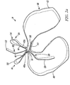
Fig. 2a is a front perspective view of the lanyard shown inFig. 1 , except the snap hooks and tethering extension have been removed; the lanyard has been removed from its packing and laid out to show the various portions and features of the lanyard; the lanyard has not been subjected to a force to tear apart its energy absorbing segments. -
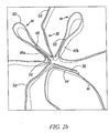
Fig. 2b is a blown-up view of a portion of the lanyard shown inFig. 2 . -
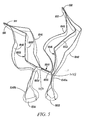
Fig. 3 is a top perspective view of a lanyard like the lanyard shown inFig. 2 ; the lanyard has been subjected to a force to partially tear apart the energy absorbing portion of the first segment and completely tear apart the energy absorbing portion of the second segment. -
Fig. 4 is top perspective view of a lanyard showing an alternative embodiment of my invention; the lanyard is packed and ready for use by a worker. -
Fig. 5 is a front perspective view of the lanyard ofFig. 5 except the snap hooks and tethering extension have been removed; the lanyard has been removed from its packing and laid out to show the various portions and features; the lanyard has not been subjected to a force to tear apart its energy absorbing segments. -
Fig. 6 is a top perspective view of a lanyard similar to a lanyard of Fig. 7; the lanyard has been subjected to a force to partially tear apart the energy absorbing portion of the first segment and the energy absorbing portion of the second segment. -
Figs. 1-3 discloses a preferredlanyard 20 which embodies the present invention. The lanyard has anenergy absorbing section 21. The energy absorbing section has afirst anchoring portion 22 at first lanyard area and asecond anchoring portion 24 at a second lanyard area. Snap hooks are at each end of the lanyard. The snap hooks can be separated a distance X from each other. The distance X is the length of the lanyard from snap hook to snap hook when the lanyard is packed and ready for use, i.e., before theenergy absorbing section 21 has been activated by a falling object. SeeFig. 1 . Althoughsection 21 is shown packed only by bands it would also be packed with a plastic shrink wrap. In the present embodiment the distance X is 4 to 6 feet. The anchoring portions during a fall can be separated a maximum distance Y. The distance Y is up to 69 inches. - As shown in
Figs. 2-3 , thelanyard 20 has anenergy absorbing section 21 which includes first 26 and second 28 segments. Under sufficient load, such as the force caused by a falling worker, an overlapping or tear apartportion 52 of the energy absorberfirst segment 26 will at least partially tear apart, and thesegment 26 will elongate.Fig. 3 shows the tear apartportion 52 partially torn apart intoportions 52a, 52b. During tearing and elongation, the distance between theanchoring portions first segment 26 resists the force of the falling worker by absorbing kinetic energy from the fall, and decelerates the worker. If the worker does not come to a complete stop by the time the energy absorber first segment tears apart a maximum allowed by the a first folded overtether portion 42, than an overlapping or tear apartportion 58 of energy absorbersecond segment 28 may begin to tear apart. Whether overlappingportion 58 of the energy absorber second segment completely tears apart depends upon the weight of the worker and distance of the fall. During a tearing apart of thesecond segment 28, the first segment continues to tear apart.Fig. 3 shows the tear apartportion 58 completely torn apart intoportions member 30. Thetethering member 30 does not elongate. Rather it unfolds from a folded or bunched orientation, seefigures 1-2 , to a less folded or unfolded or unbunched orientation. SeeFigure 3 -
Fig. 3 shows tether first 42 and second 46 folded over portions afterlanyard 20 has been subjected to a force which toreportion 52 of the first segment partially apart and theportion 58 ofsecond segment 28 completely apart. Folded overportion 42 is completely unfolded. Folded overportion 46 is partially unfolded. - In more detail the
tethering member 30 of theenergy absorbing section 21 has a first loopedportion 32 at thefirst anchoring portion 22. Thetethering member 30 has a second loopedportion 34 at thesecond anchoring portion 24. A clasp, hook, latch or other fastener 36 is coupled to the first loopedportion 32. Atether extension 33 is, coupled to the second loopedportion 34. A clasp, hook, latch or other fastener is coupled totether extension 33. Thefirst loop portion 32 andsecond loop portion 34 haverespective base portions 40a, 40b formed by stitching tether portions together. - The tether's first folded over
portion 42 extends fromsecond anchoring portion 24 to a portion of the lanyard between the first anchoring and second anchoring portion. The portion between is anintermediate portion 44. This is the tetherintermediate portion 44. - The tether's second folded over
portion 46 extends from said tetherintermediate portion 44 to said first anchoringportion 22. As explained in more detail below, the first 42 and second 46 folded over portions unfold as the first 26 andsecond segment 28 of the energy absorbing section tears apart. - The energy absorber
first segment 26 has afirst end 48 connected to thetether 30 at thefirst anchoring portion 22. More particularly it is coupled to thebase 40a of thefirst loop 32. Thefirst segment 26 has asecond end 50 coupled to thetether 30 at thesecond anchoring portion 24. More particularly, it is coupled to the base 40b of thesecond loop 34. The first segment's overlappingportion 52 extends between said first 48 and second ends 50 of saidfirst segment 26. The overlapping portion is formed from overlappingportions 52a, 52b. Theportions 52a, 52b are adhered together to formportion 52. The construction which adheres the overlappingportions 52a, 52b together exhibits a minimum arrest force of no less than 2 kilo newtons and a maximum arrest force greater than 3 kilo newtons and no more than 4 kilo newtons when subjected to a load of 160 kg which free fell from 5.9 feet. In more detail the falling object is attached to said lanyard at one end. The lanyard is attached to a fixed anchoring point at the other end. The object free falls 5.9 feet before the lanyard reaches its unfolded not yet activated length X. The object is free to continue to fall until its fall is stopped by the lanyard. The test is known as the Energy Absorbers Dynamic Drop Test. - The arrest force exhibited will go from 2 to 4 kilo newtons when subjected to the above load. The overlapping
portion 52 can be called the first energy absorbing portion of thefirst segment 26. The overlappingportion 52 has a length greater than the length of the first tether folded overportion 42. Thus, the folded overportion 42 will completely unfold prior to a complete tearing apart of the overlappingpotion 52.Fig. 4 shows the overlappingportion 52 partially torn apart intoportions 52a and 52b. - The
second segment 28 has afirst end 54 connected to thetether 30 at theintermediate portion 44. Thesecond segment 28 has asecond end 56 connected to the tether at thefirst anchoring portion 22. More particularly it is coupled to thebase 40a of the first loop. The second segment has an overlappingportion 58 which extends between the first 54 and second ends 56 of thesecond segment 28. The overlapping portion is formed from overlappingportions portions portion 58. The construction which adheres the overlappingportion 58 together has an arrest force, which when combined with the arrest force of thefirst segment 26, exhibits a minimum arrest force greater than 4 kilo newtons and a maximum arrest force greater than 5 kilo newtons but no more than 6 kilo newtons. The arrest force calculated when the segments are subjected to the load of 160 kg which free fell from 5.9 feet. The arrest force exhibited will go from 4 to at least 5.5 kilo newtons when subjected to the above load. The overlappingportion 58 can be called the secondenergy absorbing portion 58 of the second segment. The overlappingportion 58 has a length less than the length of the second tether folded overportion 46. Thus, the overlappingportion 58 will completely tear apart prior to unfolding of the second folded over portion.Fig. 4 shows the overlappingportion 58 completely torn apart intoportions - In operation when the worker falls off a support such as a scaffold and the fall creates sufficient force the overlapping
portion 52 of thefirst segment 26 begins to tear apart. The tearing apart causes thefirst segment 26 to elongate. The elongation is accompanied by an unfolding of the first folded overportion 42. The tearing apart absorbs kinetic energy from the fall thereby decreasing the speed at which a person is falling. If the person is 100 -254 lbs the persons fall will be halted prior to secondsegment overlapping portion 58 tearing apart. If the person is 254-386 pounds theenergy absorbing portion 58 of thesecond segment 28 will tear apart in a manner similar to the first segment. During a tearing apart, the second segment will elongate. The first segment will continue to elongate. The elongation will be accompanied by an unfolding of second folder over portion. The secondenergy absorbing portion 58 and first energy absorbing portion will continue to tear apart will continue to tear apart and absorb kinetic energy of the fall until the person is brought to a stop or until the secondenergy absorbing portion 58 completely tears apart, at which time the tether second folded overportion 46 will continue to unfold. As the length of thetether 30, completely unfolded, exceeds the length of the first and second segment, the first segment will continue to tear apart after the second segment has been torn apart. - The above described lanyard provides an
energy absorbing section 21 with a construction that exhibits a minimum arrest force between 0 and 3 kilo newtons and maximum arrest force between 4 and 6 kilo newtons when subjected to the above described load. More particularly the construction exhibits a minimum arrest force greater than or equal to 2 kilo newtons and a maximum arrest force greater than 5 kilo newtons and no more than 6 kilo newtons when subjected to the above described load. The construction can fairly be said to exhibit an arrest force which goes from at least 2 kilo newtons to at least 5 kilo newtons when subjected to the load of 160 kg which free fell from 5.9 feet. -
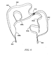
Figs. 5-8 show an alternative embodiment of alanyard 1020 which embodies the present invention.Lanyard 1020 has a construction similar toLanyard 20. For simplicity the reference numbers used to call out elements ofLanyard 1020 have been used to call out similar elements found inLanyard 20. Except the prefix "10" has been added to reference numbers of Lanyard. -
Lanyard 1020 includes first 1022 and second 1024 anchoring portions at first and second Lanyard ends. The lanyard includes atether 1030. The tethering member has a first loopedportion 1032 at thefirst anchoring portion 1022 and a second loopedportion 1034 at thesecond anchoring portion 1024. A clasp, hook, latch, or other fastener 1036 is coupled to the first looped portion. A clasp, hook, latch, or other fastener 1038 is coupled to the second looped portion. The tether has a first folded overportion 1042 between tetherintermediate portion 1044 and tether first anchoringportion 1022. The tether has a second folded overportion 1046 between tethersecond anchoring portion 1024 and tetherintermediate portion 1044. The lanyard includes an energy absorbing portion formed from first 1026 and second 1028 segments.First segment 1026 is mounted totether 1030 in a different manner thanfirst segment 26 mounts to tether 30.First segment 1026 has itsfirst end 1048 mounted to first loop base 1040a. First segment'ssecond end 1050, however, is coupled to the tetherintermediate portion 1044. - The
second segment 1028 is mounted totether 1030 in a manner different thansecond segment 28 is mounted totether 30. Thesecond segment 1028first end 1054 is mounted to the tetherintermediate portion 1044. The second segmentsecond end 1056 is mounted to the base 1040b of thesecond loop 1034. -
First segment 1026 has an overlappingportion 1052 between first 1048 and second 1050 ends ofsegment 1026.Second segment 1028 has an overlappingportion 1058 between first 1054 and second 1056 end ofsegment 1028. The first overlappingportion 1052 is formed from overlapping portions 1052a and 1052b. The first overlapping potion in this example is designed to tear apart after the second segment. Therefore the portions 1052a and 1052b of the first segment are adhered together with a construction that exhibits a minimum arrest force of at least 2 kilo newtons a and a maximum arrest force greater than 3 kilo newtons but no more than 4 kilo newtons. The arrest force thus goes from 2 to at least 3.5 kilo newtons when subjected to a load of 160 kg which free fell from 5.9 feet. The overlappingportion 1058 of the second segment has a construction so its overlappingportions portion 1052 may be stitched to thebase 102 of the first folded overportion 1042 of thetether 1030. Thebase 104 of secondsegment overlapping portion 1058 may be stitched to thebase 106 of the second folded overportion 1046 of the tether. The segments are designed to tear in series as opposed to at the same time. - Fig. 8 shows lanyard 1020 after it has been subjected to a force which tore overlapping
portion 1052 at least partially apart into portion 1052a and 1052b. The force also for overlappingportion 1058 intoportions
Claims (10)
said second tethering portion forms a second looped portion having a base.
said first end of second segment is coupled to said intermediate portion of said lanyard, said second end of said second segment is coupled to said base of said second looped portion.
said first end of said second segment is coupled to said intermediate portion of said lanyard, said second end of said second segment is coupled to said base of said second looped portion.
Applications Claiming Priority (1)
| Application Number | Priority Date | Filing Date | Title |
|---|---|---|---|
| US12/887,155 US8701826B2 (en) | 2010-09-21 | 2010-09-21 | Shock absorbing lanyard |
Publications (2)
| Publication Number | Publication Date |
|---|---|
| EP2431076A2 true EP2431076A2 (en) | 2012-03-21 |
| EP2431076A3 EP2431076A3 (en) | 2012-08-08 |
Family
ID=44651426
Family Applications (1)
| Application Number | Title | Priority Date | Filing Date |
|---|---|---|---|
| EP11181890A Withdrawn EP2431076A3 (en) | 2010-09-21 | 2011-09-19 | Shock absorbing lanyard |
Country Status (4)
| Country | Link |
|---|---|
| US (1) | US8701826B2 (en) |
| EP (1) | EP2431076A3 (en) |
| AU (1) | AU2011224137A1 (en) |
| CA (1) | CA2752418A1 (en) |
Families Citing this family (19)
| Publication number | Priority date | Publication date | Assignee | Title |
|---|---|---|---|---|
| US8584799B1 (en) * | 2011-06-28 | 2013-11-19 | Mark Dennington | Fall-arresting safety harness assembly |
| US10335619B2 (en) * | 2014-12-08 | 2019-07-02 | Fire Innovations Llc | Firefighter multifunction ladder and escape belt |
| US20160178307A1 (en) * | 2014-12-19 | 2016-06-23 | William Johnson | Hoist device with shooting aid |
| AU2016250232A1 (en) * | 2015-04-11 | 2017-11-30 | Tore BUER | Assembly for extrication and rescue |
| USD828638S1 (en) * | 2016-02-04 | 2018-09-11 | David C. Williams | Fireman's carry strap |
| US10844922B2 (en) | 2016-12-22 | 2020-11-24 | Velcro BVBA | Multi-closure energy dissipating touch fastener links |
| US10537758B2 (en) | 2016-12-22 | 2020-01-21 | Velcro BVBA | Energy dissipating touch fastener links |
| US10556701B2 (en) * | 2017-04-14 | 2020-02-11 | Rohr, Inc. | Bird-strike energy absorbing net |
| US10125837B1 (en) * | 2017-08-01 | 2018-11-13 | Honeywell International Inc. | Cylindrically rolled energy absorber for use with a self-retracting lifeline |
| US10343001B2 (en) * | 2017-09-07 | 2019-07-09 | Honeywell International Inc. | Fall protection lanyard capable of direct connection to harness webbing |
| USD834262S1 (en) | 2017-10-20 | 2018-11-20 | Werner Co. | Energy absorber cover |
| USD848884S1 (en) | 2017-10-20 | 2019-05-21 | Werner Co. | Load indicator |
| US10413762B2 (en) | 2017-10-20 | 2019-09-17 | Werner Co. | Load indicator and horizontal lifeline system including the same |
| US10512802B2 (en) * | 2017-10-20 | 2019-12-24 | Werner Co. | Energy absorber cover and horizontal lifeline system including the same |
| US10532234B2 (en) * | 2017-12-05 | 2020-01-14 | Frank C Hsu | Fall arrest lanyard with restraint relief arrangement |
| US11198027B2 (en) * | 2018-01-10 | 2021-12-14 | Sherry Green Mullins | Decelerator packed tether as an intermediate article of manufacture |
| US11633633B2 (en) * | 2018-02-09 | 2023-04-25 | 3M Innovative Properties Company | Fall protection equipment having inductive sensor for connection status and control |
| KR102159741B1 (en) * | 2019-06-19 | 2020-09-24 | 주식회사 코리아탑세이프티 | Shock absorption device comprising dual fall prevention band |
| US11511141B2 (en) | 2020-09-17 | 2022-11-29 | Korea Top Safety Co., Ltd | Shock absorption device including dual fall prevention band |
Citations (2)
| Publication number | Priority date | Publication date | Assignee | Title |
|---|---|---|---|---|
| US6533066B1 (en) | 1999-10-14 | 2003-03-18 | Rose Manufacturing Company | Lanyard with integral fall arrest energy absorber |
| US20080190691A1 (en) | 2004-03-01 | 2008-08-14 | Ykk Corporation Of America | Shock Absorbing Lanyards |
Family Cites Families (23)
| Publication number | Priority date | Publication date | Assignee | Title |
|---|---|---|---|---|
| US3444957A (en) * | 1967-12-13 | 1969-05-20 | Rose Mfg Co | Shock absorber for safety belt |
| US4100996A (en) * | 1977-06-06 | 1978-07-18 | Sharp Jonathan E | Shock absorber for a safety belt lanyard |
| US4253544A (en) * | 1980-02-11 | 1981-03-03 | Inco Safety Products Company | Energy absorbing lanyard |
| US4446944A (en) | 1983-03-09 | 1984-05-08 | Forrest Mountaineering, Inc. | Shock absorbing device and method |
| US4538702A (en) * | 1983-03-21 | 1985-09-03 | D B Industries, Inc. | Shock absorber for fall protection system |
| US5113981A (en) * | 1989-10-19 | 1992-05-19 | Lantz Michael D | Safety line shock absorber |
| US5090503A (en) * | 1990-10-29 | 1992-02-25 | Michael Bell | Visually inspectable safety lanyard |
| US5316102A (en) * | 1992-02-12 | 1994-05-31 | Michael Bell | Safety system for use in erecting static structures |
| GB9314063D0 (en) | 1993-07-06 | 1993-08-18 | Latchways Ltd | Shock absorber |
| DE9401314U1 (en) * | 1994-01-26 | 1994-04-07 | Trw Repa Gmbh, 73553 Alfdorf | Seat belt with tear seam |
| US5598900A (en) * | 1994-10-21 | 1997-02-04 | Surety Manufacturing & Testing Ltd. | Horizontal lifeline energy absorber |
| US5960480A (en) * | 1995-05-26 | 1999-10-05 | Otis Elevator Company | Fall protection safety suit |
| US5658012A (en) * | 1995-11-02 | 1997-08-19 | Trw Vehicle Safety Systems Inc. | Seat belt webbing energy management device |
| US6581725B2 (en) * | 2000-08-31 | 2003-06-24 | Gary E. Choate | Method to reduce horizontal lifeline tension and extension during fall arrest |
| US6883640B2 (en) * | 2001-05-24 | 2005-04-26 | Michael P. Kurtgis | Fall protection lanyard apparatus |
| US6990928B2 (en) * | 2001-05-24 | 2006-01-31 | Kurtgis Michael P | Method for providing fall protection for a load in an elevated environment |
| US6648101B2 (en) * | 2001-05-24 | 2003-11-18 | Michael P. Kurtgis | Fall protection lanyard apparatus |
| FR2836052B1 (en) * | 2002-02-20 | 2004-04-02 | Zedel | FASTENING DEVICE WITH ENERGY ABSORBER AND SAFETY LONGS |
| US7237650B2 (en) * | 2004-05-19 | 2007-07-03 | D B Industries, Inc. | Tension device for use with a self-retracting lifeline |
| US7392881B1 (en) * | 2004-09-09 | 2008-07-01 | Choate Gary E | Multiple stage personal fall arrest energy absorber |
| EP1915548B1 (en) * | 2005-08-16 | 2016-03-09 | YKK Corporation of America | Energy absorbing webbings |
| US20100252361A1 (en) * | 2009-04-02 | 2010-10-07 | Wood Norman E | Controlled descent system with an increased recovery range |
| US8675823B2 (en) * | 2009-10-30 | 2014-03-18 | Hooten Investments, Inc. | Method and apparatus for activating a communication device operably connected to a safety lanyard |
-
2010
- 2010-09-21 US US12/887,155 patent/US8701826B2/en not_active Expired - Fee Related
-
2011
- 2011-09-19 EP EP11181890A patent/EP2431076A3/en not_active Withdrawn
- 2011-09-19 CA CA2752418A patent/CA2752418A1/en not_active Abandoned
- 2011-09-20 AU AU2011224137A patent/AU2011224137A1/en not_active Abandoned
Patent Citations (2)
| Publication number | Priority date | Publication date | Assignee | Title |
|---|---|---|---|---|
| US6533066B1 (en) | 1999-10-14 | 2003-03-18 | Rose Manufacturing Company | Lanyard with integral fall arrest energy absorber |
| US20080190691A1 (en) | 2004-03-01 | 2008-08-14 | Ykk Corporation Of America | Shock Absorbing Lanyards |
Also Published As
| Publication number | Publication date |
|---|---|
| AU2011224137A1 (en) | 2012-04-05 |
| US20120067666A1 (en) | 2012-03-22 |
| US8701826B2 (en) | 2014-04-22 |
| EP2431076A3 (en) | 2012-08-08 |
| CA2752418A1 (en) | 2012-03-21 |
Similar Documents
| Publication | Publication Date | Title |
|---|---|---|
| US8701826B2 (en) | Shock absorbing lanyard | |
| EP3551296B1 (en) | Harness with integrated energy absorber | |
| US8584799B1 (en) | Fall-arresting safety harness assembly | |
| US9643034B2 (en) | Fall arrest system and lanyard | |
| EP0034458B1 (en) | An energy absorbing lanyard and a safety belt or harness comprising such a lanyard | |
| US10702723B2 (en) | Harness with structural tear tape | |
| KR100626420B1 (en) | Safety belt of shock absorption for high place work | |
| US20070095873A1 (en) | Roping belt equipped with an improved equipment-carrying device | |
| WO1994021328A1 (en) | Shock-absorbing safety harness | |
| WO2013063196A2 (en) | Energy absorber | |
| CA3106842C (en) | Energy absorber coil for safety harness | |
| GB2585595A (en) | Shock absorbing leash | |
| KR20150136555A (en) | Lanyard for safety belt | |
| RU2557748C2 (en) | Safety harness | |
| KR102428779B1 (en) | Safety belt to prevent fall | |
| WO2019175543A1 (en) | Energy absorber device | |
| JP2020195518A (en) | Lanyard | |
| CN210472831U (en) | Falling safety protection device integrating falling cushioning protection and self-rescue after falling suspension | |
| WO2007110580A1 (en) | Safety lanyard | |
| JP2017205153A (en) | Fall prevention device | |
| JP2024008397A (en) | Lanyard for crash arrest appliance, and crash arrest appliance | |
| JPH0810317Y2 (en) | Safety belt for fall prevention with a buffer belt | |
| CA2109285A1 (en) | Energy absorbing lanyard |
Legal Events
| Date | Code | Title | Description |
|---|---|---|---|
| PUAI | Public reference made under article 153(3) epc to a published international application that has entered the european phase |
Free format text: ORIGINAL CODE: 0009012 |
|
| 17P | Request for examination filed |
Effective date: 20110919 |
|
| AK | Designated contracting states |
Kind code of ref document: A2 Designated state(s): AL AT BE BG CH CY CZ DE DK EE ES FI FR GB GR HR HU IE IS IT LI LT LU LV MC MK MT NL NO PL PT RO RS SE SI SK SM TR |
|
| AX | Request for extension of the european patent |
Extension state: BA ME |
|
| PUAL | Search report despatched |
Free format text: ORIGINAL CODE: 0009013 |
|
| AK | Designated contracting states |
Kind code of ref document: A3 Designated state(s): AL AT BE BG CH CY CZ DE DK EE ES FI FR GB GR HR HU IE IS IT LI LT LU LV MC MK MT NL NO PL PT RO RS SE SI SK SM TR |
|
| AX | Request for extension of the european patent |
Extension state: BA ME |
|
| RIC1 | Information provided on ipc code assigned before grant |
Ipc: A62B 35/04 20060101AFI20120703BHEP Ipc: F16F 7/00 20060101ALI20120703BHEP |
|
| 17Q | First examination report despatched |
Effective date: 20120924 |
|
| RAP1 | Party data changed (applicant data changed or rights of an application transferred) |
Owner name: HONEYWELL INTERNATIONAL INC. |
|
| STAA | Information on the status of an ep patent application or granted ep patent |
Free format text: STATUS: THE APPLICATION IS DEEMED TO BE WITHDRAWN |
|
| 18D | Application deemed to be withdrawn |
Effective date: 20170401 |