EP2430486B1 - Montage de maintien avec precision d'un composant, notamment optique - Google Patents
Montage de maintien avec precision d'un composant, notamment optique Download PDFInfo
- Publication number
- EP2430486B1 EP2430486B1 EP10718611A EP10718611A EP2430486B1 EP 2430486 B1 EP2430486 B1 EP 2430486B1 EP 10718611 A EP10718611 A EP 10718611A EP 10718611 A EP10718611 A EP 10718611A EP 2430486 B1 EP2430486 B1 EP 2430486B1
- Authority
- EP
- European Patent Office
- Prior art keywords
- component
- levers
- base
- devices
- plane
- Prior art date
- Legal status (The legal status is an assumption and is not a legal conclusion. Google has not performed a legal analysis and makes no representation as to the accuracy of the status listed.)
- Not-in-force
Links
- 230000003287 optical effect Effects 0.000 title claims description 17
- 238000013519 translation Methods 0.000 claims description 25
- 230000014616 translation Effects 0.000 claims description 25
- 230000005484 gravity Effects 0.000 claims description 10
- 230000000712 assembly Effects 0.000 description 5
- 238000000429 assembly Methods 0.000 description 5
- 238000010586 diagram Methods 0.000 description 3
- 230000000694 effects Effects 0.000 description 3
- 230000001154 acute effect Effects 0.000 description 1
- 238000004026 adhesive bonding Methods 0.000 description 1
- 238000005452 bending Methods 0.000 description 1
- 230000000903 blocking effect Effects 0.000 description 1
- 239000011248 coating agent Substances 0.000 description 1
- 238000000576 coating method Methods 0.000 description 1
- 230000000295 complement effect Effects 0.000 description 1
- 239000003292 glue Substances 0.000 description 1
- 230000010354 integration Effects 0.000 description 1
- 238000012423 maintenance Methods 0.000 description 1
- 210000004417 patella Anatomy 0.000 description 1
- 230000036544 posture Effects 0.000 description 1
Images
Classifications
-
- G—PHYSICS
- G02—OPTICS
- G02B—OPTICAL ELEMENTS, SYSTEMS OR APPARATUS
- G02B7/00—Mountings, adjusting means, or light-tight connections, for optical elements
- G02B7/18—Mountings, adjusting means, or light-tight connections, for optical elements for prisms; for mirrors
- G02B7/182—Mountings, adjusting means, or light-tight connections, for optical elements for prisms; for mirrors for mirrors
Definitions
- the subject of the invention is an assembly for accurately holding an optical component.
- the optical component can be fixed by its edge in a frame, or fixed by its rear face.
- Some means include coating in an elastomeric seal or in flexible glue, fixing by a rigid bonding, a rigid bonding with elastic support blades, or clamping in three or four points.
- isostatic support systems composed of articulated arms or more generally of elastic deformable parts, which have the general advantage of keeping the component at a precise and stable position without transmitting significant stresses under the differential thermal deformations.
- Good integration of the component, under reduced bulk, is also made possible by these systems.
- isostatic holding systems are difficult to implement on thin and non-circular components based on the edge of the component. We are therefore led to look at isostatic postures by the rear of the component, but the existing systems reveal the disadvantage of being sensitive to the deformations due to the own weight of the component while undergoing distortions which distort the position or the orientation of the component.
- the subject of the invention is an assembly in which is employed at least one isostatic holding device of a vertically placed optical component which is devoid of the latter disadvantage.
- the invention in a general form, relates to a mounting comprising a support, an optical component and at least one holding device comprising a base, an end, two levers extending between the base and the end at an angle and converging towards the end, the levers being articulated to the base and the end so as to be rotatable in a plane where they both extend, the component being fixed at the end of the device and the base being fixed to the support, characterized in that, the component being placed vertically, a point where axes of the levers intersect is in the same vertical plane s extending to a median depth of the component and to which belongs the center of gravity of the component, a plane where the levers of the device extend being also vertical.
- the point of intersection of the axes of the levers defines a virtual pivot of rotation of the optical component intended to be fixed at the end of the device. It is close to the average line of the component, to which its center of gravity belongs.
- the cantilever between the virtual pivot and the point of application of the weight of the component is low or zero, so that the deformations of the holding device due to the self weight of the component does not result in a significant deformation of the -this.
- the levers are articulated to the support and at the end by elastic blades.
- the isostatic nature of the assembly can be reinforced if the levers are still articulated to the base and the end so as to be movable in rotation perpendicular to the previously defined plane.
- the levers are articulated to the base and the end by pairs of elastic blades arranged in series along the levers, each pair comprising a blade oriented in said plane and a blade perpendicular to said plane.
- An assembly according to the invention comprises a support, an optical component and at least two devices each in accordance with the foregoing, the component being fastened to the end of each device and the base of each device being fixed to the support, characterized in that, for each of the devices, the point where the axes of the levers intersect is in the same vertical plane close to the center of gravity of the component, a vertical line originating from the center of gravity passing between said points where the axes of the levers intersect. In this case, the devices must be placed symmetrically with respect to the vertical line.
- the isostaticity of the assembly is well respected if the component is fixed to the support by three devices, which stops each of the translations of the component in two directions, either stop translations in one direction, two directions and three directions, respectively.
- the three devices fixing the component to the support all comprise levers hinged to a base fixed in the support and at one end fixed to the component.
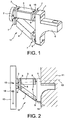
- FIG. 1 An important embodiment of a holding device 17 used in the invention appears at the figure 1 . It comprises a base 1, an end 2, and an upper lever 3 and a lower lever 4 each extending between the base 1 and the end 2.
- the upper lever 3 and the lower lever 4 are in a common plane that it will be called vertical with reference to its most typical position when the device is in use. It makes an acute angle that converges towards the end 2.
- the base 1 is composed of a main vertical portion 5 at which the ends of the levers 3 and 4 are fixed. and a post 6 (opposite to the levers 3 and 4 relative to the main portion 5) which is intended to be embedded in a fixed structure.
- Each of the levers 3 and 4 is articulated to the main portion 5 by a hinge 7 composed of a vertical blade 8 joined to the levers 3 or 4, a horizontal blade 9 joined to the main portion 5 and a junction 10 joining the blades 8 and 9; the joints allow movements of the rotations of the levers 3 and 4 in the vertical direction and in the horizontal direction thanks to the flexibility of the blades 9 and 8 and therefore constitute joints with two degrees of freedom of rotation.
- the levers 3 and 4 are connected to the end 2 by other similar joints 7, the vertical blades 8 are still joined to the levers 3 and 4 and the horizontal 9 being this time joined to the end 2.
- FIG. figure 2 The typical assembly of this device 17 is illustrated in FIG. figure 2 the base 1 is fixed to a fixed support structure 11, and an optical component 12 such as a mirror is attached to the end 2, for example by gluing.
- the levers 3 and 4 have hinge pins 13 and 14 belonging to the same plane and passing through the horizontal blades 9, which have a point of intersection 15 located slightly in front of the end 2 and which advantageously extends into the optical component 12, and more precisely at a median depth, in a vertical plane originating from the center of gravity 16 of the component 12 or at least in the vicinity: the gravity loads experienced by the device 17 due to the weight of the component 12 induce a rotation of levers 3 and 4, but who produced a simple vertical movement of the component 12, without tilting, which would change its shape. Limiting the deformation of the component is an important effect of the invention.
- An isostatic assembly includes the removal of the six degrees of freedom without redundancy (three translations and three rotations) of the component 12, by a series of support connection elements 11 judiciously chosen and placed. These elements must have on their side internal degrees of flexibility flexibility to avoid the hyperstaticity of the assembly.
- the usual elements block the movement of the component 12 in one, two or three main directions (X, Y and Z) translation.
- a "plane element” is called a link that blocks a translation direction, "line element” a link that blocks two translation directions and "point element” a link that blocks three translation directions.
- the isostatic assembly is thus usually obtained by combinations of a line element, a point element and a plane element or three dashed elements. The combinations of six planar elements come back to a combination of three features.
- a patella allows three rotations and blocks three translations and is therefore a point element.
- the serialization of two ball joints blocks a single translation and constitutes a planar element.
- a ball joint in series with an axis of rotation constitutes a line element.
- a short blade allows a single rotation.
- Two perpendicular short blades allow two rotations in series, and if the two bending axes are parallel to the rear face of the component 12, the blades can be considered together as a point element.
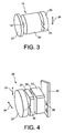
- the short wire 19 is equivalent to a ball joint allowing three rotations between the end 22 and the junction 23, and it therefore constitutes a point element. If the wire was longer, or if we had two short son in series, a single translation (in the alignment of the ends 20 and 22) would be blocked and we would have a plane element.
- the device 18 of the figure 3 consisting of a blade 21 in series with a short wire 19, allows a single translation between the ends 20 and 22 (in the direction 24 perpendicular to the blade 21) and therefore constitutes a dashed element.
- FIG. 4 Another trait element 35 is illustrated in figure 4 and comprises, between two ends 26 and 27, successively a horizontal blade 28, a vertical blade 29 and a horizontal blade 30, junctions 31 and 32 connecting the blades 28 and 29, then the blades 28 and 30. It can be seen that this element allows translations along the vertical direction 33 between the ends 26 and 27, while translations allowed in the horizontal direction 34 are smaller and even negligible because of the short length of the blade 29.
- the device 17 described above can be considered as a line element, since the levers 3 and 4 both allow translation of the component 12 in the horizontal direction relative to the support 1, but block the vertical translations despite the flexibility of the joints 7.
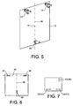
- the figure 5 illustrates a first isostatic mounting of the optical component 12. It is held by two devices 17 and a device 35 in accordance with the figure 4 , all attached to its back side.
- the two devices 17 are placed at the upper right and left corners, symmetrically with respect to the central vertical line 36 of the component 12 (originating from the center of gravity 16), at the same height, and their levers 3 and 4 extend in vertical planes.
- the element 35 is at the bottom of the component 12, on the central line 36, and is oriented as shown in FIG. figure 4 , with two of its blades (28 and 30) horizontal and one (29) vertical.
- the elements 17 both allow the horizontal translations of the component 12, but block the vertical translations, while the device 35 has the opposite effect of allowing the vertical translations while blocking the horizontal translations.
- the diagram can be represented at figure 6 37 and 38 are the movements authorized by the devices 17 and 39, respectively, by the movements authorized by the element 35.
- the movements 37 and 38 are aligned on a horizontal line 40, the movement 39 is aligned on a line vertical 36 which cuts the previous one with a general shape T.
- the isostatic assembly is obtained, in accordance with the criterion mentioned above of a connection to three elements concurrent features, since the devices 17 and 35 absorb complementary forces.
- the assembly of the figure 7 looks like that of the figure 6 except that the dashed elements allowing horizontal movements (here 41 and 42) are at the bottom of the component 12 and that the line element allowing the vertical movements 43 is located at the top, possibly being at the center of the component 12 or has a from its angles, what is represented here.
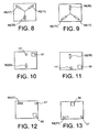
- the montages Figures 8 and 9 look like those of Figures 6 and 7 , but the movements (44, 45, 46 or 47) authorized by the devices 17 are this time oblique, which can be obtained by arranging obliquely the planes where the levers 3 and 4 extend, contrary to what has been proposed so far. There are devices 35 allowing vertical movements 48 and 49. The convergence of the directions of the movements 44, 45 and 48 or 46, 47 and 49 can still easily be respected.
- mounts with a line element, a point element and a plane element are also possible and the invention can improve them.
- devices according to the invention and similar to the devices 17 will be used, where the joints 7 will only be replaced by short horizontal blades (similar to the blades 9), thus directly joining the levers 3 and 4 to either the main portion 5 of the base 1, at the end 2; these devices will have the reference 17 'and will correspond to points elements in that they will no longer allow the horizontal translation between the component 12 and the fixed structure 11 and thus block their three main translations.
- the assembly of the figure 10 comprises a device 17 'at the top and in the middle of the component 12, a device such as 35 associated with a vertical movement line element 50, at the bottom and in the middle as at the assemblies of the figures 6 and 8 , and a device associated with a plane element 51 elsewhere, for example at an upper corner.
- the figure 11 describes a symmetrical mounting with respect to a central line of the component 12, that is to say with the device 17 'at the bottom center, the device 35 at the top center (still allowing a vertical movement 52) and a planar element 53 at a lower corner.
- the assembly of the figure 12 comprises a device 17 allowing horizontal movement (as in the Figures 6 and 7 ) 54 at an upper corner, a device 17 'on the line of movement 54 at the opposite upper corner, and a plane element 55 at a lower corner, for example on the side of the device 17'.
- the device could be placed elsewhere, as illustrated by figure 13 where the devices 17 and 17 'are this time placed on a lower line of the component 12 and the plane element at the top of the component 12.
- the devices 17 have the same property as the devices 17 to support the weight of the component 12 without allowing its tilting due to the position of the point of intersection 15 of the axes 13 and 14 at mid-depth of the component, so that the assemblies two elements traits in accordance with the invention may be replaced by a line element and a point element (in accordance with the invention,) being distinguished previous montages also in that the third element will be a planar element.
Landscapes
- Physics & Mathematics (AREA)
- General Physics & Mathematics (AREA)
- Optics & Photonics (AREA)
- Mounting And Adjusting Of Optical Elements (AREA)
Description
- Le sujet de l'invention est un montage de maintien avec précision d'un composant optique.
- Un maintien à une position précise est recherché pour des composants optiques tels que des miroirs, dont la plus petite rotation ou déformation peut affecter l'appareillage auquel ils appartiennent ; mais il est difficile à assurer avec simplicité pour des composants optiques minces et de grandes dimensions, puisque les déformations dues au poids propre du composant peuvent jouer un rôle important quand le composant est placé verticalement. Les déformations d'origine thermique ont aussi un effet important sur la qualité de nombreux dispositifs de maintien. Enfin, l'utilisation de composants de section non circulaire complique l'emploi de certains montages.
- Le composant optique peut être fixé par sa tranche dans un cadre, ou fixé par sa face arrière. Certains moyens comprennent l'enrobage dans un joint en élastomère ou dans de la colle souple, une fixation par un collage rigide, un collage rigide conjoint à des lames élastiques de support, ou des bridages en trois ou quatre points. Certains de ces montages sont souples et ont alors l'inconvénient d'être imprécis en étant insuffisamment rigides et stables; d'autres sont des fixations rigides qui garantissent une position précise du composant, mais ils ont l'inconvénient de transmettre des efforts importants provenant notamment des dilatations thermiques différentielles entre le composant et son support. Et certains sont difficilement applicables à des composants de grande taille et de section rectangulaire.
- Il existe encore des systèmes de maintien isostatique composés de bras articulés ou plus généralement de pièces déformables élastiques, qui ont l'avantage général de maintenir le composant à une position précise et stable sans lui transmettre de contraintes importantes sous les déformations thermiques différentielles. Une bonne intégration du composant., sous encombrement réduit, est aussi rendue possible par ces systèmes. Toutefois, ces systèmes de maintien isostatique sont difficiles à mettre en oeuvre sur des composants de faible épaisseur et non circulaires en s'appuyant sur la tranche du composant. On est donc conduit à s'intéresser à des maintiens isostatiques par l'arrière du composant, mais les systèmes existants laissent apparaître l'inconvénient d'être sensibles aux déformations dues au poids propre du composant en subissant des déformations qui faussent la position ou l'orientation du composant.
- Le sujet de l'invention est un montage dans lequel est employé au moins un dispositif de maintien isostatique d'un composant optique placé verticalement qui soit dépourvu de ce dernier inconvénient.
- Sous une forme générale, l'invention concerne un montage comprenant un support, un composant optique et au moins un dispositif de maintien comprenant une embase, une extrémité, deux leviers s'étendant entre l'embase et l'extrémité en faisant un angle et en convergeant vers l'extrémité, les leviers étant articulés à l'embase et à l'extrémité de façon à être mobiles en rotation dans un plan où ils s'étendent tous deux, le composant étant fixé à l'extrémité du dispositif et l'embase étant fixée au support, caractérisé en ce que, le composant étant placé verticalement, un point où des axes des leviers se coupent est dans un même plan vertical s'étendant à une profondeur médiane du composant et auquel appartient le centre de gravité du composant, un plan où les leviers du dispositif s'étendent étant aussi vertical.
- De tels dispositifs à deux leviers concourants ont déjà été employés pour soutenir des miroirs (
FR-A- 2 773 890 EP-A- 1 962 124 ,DE-A- 44 26 160 etFR-A- 2 770 308 - Le point d'intersection des axes des leviers définit un pivot virtuel de rotation du composant optique destiné à être fixé à l'extrémité du dispositif. Il est proche de la ligne moyenne du composant, à laquelle appartient son centre de gravité. Le porte-à-faux entre le pivot virtuel et le point d'application du poids du composant est faible ou nul, de sorte que les déformations du dispositif de maintien dues au poids propre du composant ne se traduisent pas par une déformation importante de celui-ci.
- Dans une conception simple et avantageuse, les leviers sont articulés au support et à l'extrémité par des lames élastiques.
- Le caractère isostatique du montage peut être renforcé si les leviers sont encore articulés à l'embase et à l'extrémité de façon à être aussi mobiles en rotation perpendiculairement au plan précédemment défini.
- Dans une forme particulière importante, les leviers sont articulés à l'embase et à l'extrémité par des paires de lames élastiques disposées en série le long des leviers, chacune des paires comprenant une lame orientée dans ledit plan et une lame perpendiculaire audit plan.
- Un montage conforme à l'invention comprend un support, un composant optique et au moins deux dispositifs chacun conformes à ce qui précède, le composant étant fixé à l'extrémité de chaque dispositif et l'embase de chaque dispositif étant fixée au support, caractérisé en ce que, pour chacun des dispositifs, le point où les axes des leviers se coupent est dans un même plan vertical proche du centre de gravité du composant, une ligne verticale originaire du centre de gravité passant entre lesdits points où les axes des leviers se coupent. Dans ce cas, les dispositifs doivent être placés symétriquement par rapport à la ligne verticale.
- Quoi qu'il en soit, l'isostaticité du montage est bien respectée si le composant est fixé au support par trois dispositifs, qui soit arrêtent chacun des translations du composant dans deux directions, soit arrêtent respectivement des translations dans une direction, deux directions et trois directions.
- Dans une forme particulière de ce montage isostatique, les trois dispositifs fixant le composant au support comprennent tous des leviers articulés à une embase fixée dans le support et à une extrémité fixée au composant.
- L'invention sera maintenant décrite en liaison aux figures suivantes:
- les
figures 1 et 2 illustrent un dispositif de maintien utilisé dans l'invention, - les
figures 3 et 4 illustrent deux autres dispositifs de maintien, - la
figure 5 illustre un montage conforme à l'invention, - la
figure 6 est en schéma fonctionnel du montage de lafigure 5 , - et les
figures 7 ,8, 9, 10, 11, 12 et 13 sont des schémas fonctionnels d'autres montages. - Un mode de réalisation important d'un dispositif 17 de maintien utilisé dans l'invention apparaît à la
figure 1 . Il comprend une embase 1, une extrémité 2, et un levier supérieur 3 et un levier inférieur 4 s'étendant chacun entre l'embase 1 et l'extrémité 2. Le levier supérieur 3 et le levier inférieur 4 sont dans un plan commun que l'on appellera vertical en référence à sa position la plus typique quand le dispositif sera en service. Il fait un angle aigu qui converge vers l'extrémité 2. L'embase 1 est composée d'une portion principale 5 verticale à laquelle les extrémités des leviers 3 et 4 sont fixées et d'un tenon 6 postérieur (opposé aux leviers 3 et 4 par rapport à la portion principale 5) qui est destiné à être encastré dans une structure fixe. Chacun des leviers 3 et 4 est articulé à la portion principale 5 par une articulation 7 composée d'une lame verticale 8 jointe aux leviers 3 ou 4, d'une lame horizontale 9 jointe à la portion principale 5 et d'une jonction 10 joignant les lames 8 et 9; les articulations permettent des mouvements des rotations des leviers 3 et 4 en direction verticale et en direction horizontale grâce à la souplesse des lames 9 et 8 et constituent donc des articulations à deux degrés de liberté de rotation. Les leviers 3 et 4 sont reliés à l'extrémité 2 par d'autres articulations 7 analogues, les lames verticales 8 sont encore jointes aux leviers 3 et 4 et les horizontales 9 étant cette fois jointes à l'extrémité 2. - Le montage typique de ce dispositif 17 est illustré à la
figure 2 : l'embase 1 est fixée à une structure fixe de support 11, et un composant optique 12 tel qu'un miroir est fixé à l'extrémité 2, par exemple par collage. Les leviers 3 et 4 possèdent des axes d'articulation 13 et 14 appartenant à un même plan et passant par les lames horizontales 9, qui possèdent un point d'intersection 15 situé un peu devant l'extrémité 2 et qui s'étend avantageusement dans le composant optique 12, et plus précisément à une profondeur médiane, dans un plan vertical originaire du centre de gravité 16 du composant 12 ou du moins à proximité: les efforts de gravité subis par le dispositif 17 en raison du poids du composant 12 induisent une rotation des leviers 3 et 4, mais qui produit un simple mouvement vertical du composant 12, sans basculement, qui modifierait sa forme. La limitation de la déformation du composant est un effet important de l'invention. - Dans la suite de cette description, on décrira certains montages isostatiques du composant 12 employant un dispositif tel que celui (17) des
figures 1 et 2 , mais certaines considérations générales vont d'abord être introduites. Le composant 12 sera supposé vertical. - Un montage isostatique comporte la suppression des six degrés de liberté sans redondance (trois translations et trois rotations) du composant 12, par une série d'éléments de liaison au support 11 judicieusement choisis et placés. Ces éléments doivent posséder de leur côté des degrés de liberté internes de souplesse afin d'éviter l'hyperstaticité du montage. Les éléments usuels bloquent le mouvement du composant 12 en une, deux ou trois directions principales (X, Y et Z) de translation. On appelle un «élément plan» une liaison qui bloque une direction de translation, «élément trait» une liaison qui bloque deux directions de translation et «élément point» une liaison qui bloque trois directions de translation. Le montage isostatique est donc obtenu usuellement par des combinaisons d'un élément trait, un élément point et un élément plan ou de trois éléments traits. Les combinaisons de six éléments plans reviennent à une combinaison de trois éléments traits. Si trois éléments sont dans un même plan (la face arrière du composant 12) et si un élément point est aligné sur un élément trait, ou si les trois éléments traits concourent en un seul point, les variations de distance entre les éléments, dues aux dilatations thermiques par exemple, ne créent pas de déformation du composant 12.
- Voici des exemples de classification de dispositifs concrets de support parmi ces éléments. Une rotule autorise trois rotations et bloque trois translations et constitue donc un élément point. La mise en série de deux rotules bloque une seule translation et constitue un élément plan. Une rotule en série avec un axe de rotation constitue un élément trait.
- Considérons maintenant des lames élastiques analogues aux lames 8 et 9 déjà rencontrées. Une lame courte autorise une seule rotation. Deux lames courtes perpendiculaires autorisent en série deux rotations, et si les deux axes de flexion sont parallèles à la face arrière du composant 12, les lames peuvent être considérées ensemble comme un élément point.
- Un autre exemple de dispositif de maintien 18, donné à la
figure 3 , comprend, entre ses deux extrémités 22 et 20, une lame 21 et un fil 19 court avec une jonction 23 intermédiaire. Le fil 19 court est équivalent à une rotule autorisant trois rotations entre l'extrémité 22 et la jonction 23, et il constitue donc un élément point. Si le fil était plus long, ou si on disposait deux fils courts en série, une seule translation (dans l'alignement des extrémités 20 et 22) serait bloquée et on aurait un élément plan. Le dispositif 18 de lafigure 3 , composé d'une lame 21 en série avec un fil 19 court, autorise une seule translation entre les extrémités 20 et 22 (dans la direction 24 perpendiculaire à là lame 21) et constitue donc un élément trait. Un autre élément trait 35 est illustré à lafigure 4 et comprend, entre deux extrémités 26 et 27, successivement une lame 28 horizontale, une lame 29 verticale et une lame 30 horizontale, des jonctions 31 et 32 reliant les lames 28 et 29, puis les lames 28 et 30. On s'aperçoit que cet élément autorise des translations le long de la direction verticale 33 entre les extrémités 26 et 27, alors que des translations autorisées dans la direction horizontale 34 sont plus réduites et même négligeables à cause de la faible longueur de la lame 29. - L'homme du métier pourra facilement concevoir d'autres reconstitutions d'éléments points, traits et plans d'après les indications précédentes et les possibilités de combinaisons entre les liaisons élémentaires. Le dispositif 17 décrit plus haut peut être considéré comme un élément trait, puisque les leviers 3 et 4 autorisent tous deux des translations du composant 12 dans la direction horizontale par rapport au support 1, mais bloquent les translations verticales malgré la souplesse des articulations 7.
- La
figure 5 illustre un premier montage isostatique du composant optique 12. Il est maintenu par deux dispositifs 17 et un dispositif 35 conforme à lafigure 4 , tous fixés à sa face arrière. Les deux dispositifs 17 sont placés aux coins supérieurs droit et gauche, symétriquement par rapport à la ligne verticale centrale 36 du composant 12 (originaire du centre de gravité 16), à la même hauteur, et leurs leviers 3 et 4 s'étendent dans des plans verticaux. L'élément 35 est en bas du composant 12, sur la ligne centrale 36, et il est orienté de la façon représentée à lafigure 4 , avec deux de ses lames (28 et 30) horizontales et une (29) verticale. Les éléments 17 autorisent tous deux les translations horizontales du composant 12, mais bloquent les translations verticales, alors que le dispositif 35 a l'effet inverse d'autoriser les translations verticales tout en bloquant les translations horizontales. Leur combinaison bloque donc les trois translations (y compris perpendiculairement au composant 12). Le schéma peut être représenté à lafigure 6 , où on a symbolisé par 37 et 38 les mouvements autorisés respectivement par les dispositifs 17 et par 39 les mouvements autorisés par l'élément 35. Les mouvements 37 et 38 sont alignés sur une ligne horizontale 40, le mouvement 39 est aligné sur une ligne verticale 36 qui coupe la précédente avec une forme générale de T. Le montage isostatique est obtenu, en respectant le critère mentionné plus haut d'une liaison à trois éléments traits concourants, puisque les dispositifs 17 et 35 absorbent des efforts complémentaires. - Les dernières figures de la description schématisent d'autres modes de réalisation possibles. Le montage de la
figure 7 ressemble à celui de lafigure 6 , si ce n'est que les éléments traits autorisant des mouvements horizontaux (ici 41 et 42) sont en bas du composant 12 et que l'élément trait autorisant les mouvements verticaux 43 est situé en haut en pouvant être au centre du composant 12 ou à un de ses angles, ce que l'on a représenté ici. Ce sont encore des dispositifs 17 qui autorisent les mouvements horizontaux 41 et 42 et un dispositif 35 qui autorise les mouvements verticaux 43; le maintien isostatique du composant 12 est respecté si les positions des dispositifs 17 et 35 varient, tant que la condition de concours des lignes des mouvements 41, 42, 43 subsiste. - Les montages des
figures 8 et 9 ressemblent à ceux desfigures 6 et 7 , mais les mouvements (44, 45, 46 ou 47) autorisés par les dispositifs 17 sont cette fois obliques, ce qui peut être obtenu en disposant obliquement les plans où s'étendent les leviers 3 et 4, contrairement à ce qu'on a proposé jusqu'ici. On retrouve des dispositifs 35 autorisant des mouvements verticaux 48 et 49. La convergence des directions des mouvements 44, 45 et 48 ou 46, 47 et 49 peut encore facilement être respectée. - Ainsi qu'on l'a mentionné, des montages à un élément trait, un élément point et un élément plan sont également possibles et l'invention peut les perfectionner. On recourra alors par exemple à des dispositifs, conformes à l'invention et analogues aux dispositifs 17, où les articulations 7 seront seulement remplacées par des lames horizontales courtes (analogues aux lames 9), joignant donc directement les leviers 3 et 4 soit à la portion principale 5 de l'embase 1, soit à l'extrémité 2; ces dispositifs auront la référence 17' et correspondront à des éléments points en ce qu'ils n'autoriseront plus la translation horizontale entre le composant 12 et la structure fixe 11 et bloqueront donc leurs trois translations principales.
- Le montage de la
figure 10 comprend un dispositif 17' en haut et au milieu du composant 12, un dispositif tel que 35 associé à un élément trait à mouvement vertical 50, en bas et au milieu comme aux montages desfigures 6 et8 , et un dispositif associé à un élément plan 51 ailleurs, par exemple à un coin supérieur. Lafigure 11 décrit un montage symétrique par rapport à une ligne centrale du composant 12, c'est-à-dire avec le dispositif 17' en bas au centre, le dispositif 35 en haut au centre (autorisant encore un mouvement vertical 52) et un élément plan 53 à un coin inférieur. Le montage de lafigure 12 comprend un dispositif 17 autorisant un mouvement horizontal (comme dans lesfigures 6 et 7 ) 54 à un coin supérieur, un dispositif 17' sur la ligne du mouvement 54 au coin supérieur opposé, et un élément plan 55 à un coin inférieur, par exemple du côté du dispositif 17'. Le dispositif pourrait être placé ailleurs, ce qu'illustre lafigure 13 où les dispositifs 17 et 17' sont cette fois placés sur une ligne inférieure du composant 12 et l'élément plan en haut du composant 12. - Les dispositifs 17' possèdent la même propriété que les dispositifs 17 de soutenir le poids du composant 12 sans permettre son basculement grâce à la position du point d'intersection 15 des axes 13 et 14 à mi-profondeur du composant, de sorte que les montages à deux éléments traits conformes à l'invention pourront être remplacés par un élément trait et un élément point (conformes à l'invention,) se distinguant des montages précédents aussi en ce que le troisième élément sera un élément de type plan.
Claims (8)
- Montage comprenant un support, un composant (12) optique et au moins un dispositif (17) de maintien comprenant une embase (1), une extrémité (2), deux leviers (3, 4) s'étendant entre l'embase (1) et l'extrémité (2) en faisant un angle et en convergeant vers l'extrémité, les leviers étant articulés à l'embase et à l'extrémité de façon à être mobiles en rotation dans un plan où ils s'étendent tous deux, le composant optique étant fixé à l'extrémité du dispositif et l'embase étant fixée au support, caractérisé en ce que, le composant étant placé verticalement, un point (15) où des axes des leviers se coupent est dans un plan vertical s'étendant à une profondeur médiane du composant optique et auquel appartient le centre de gravité (16) du composant , un plan où les leviers du dispositif s'étendent étant aussi vertical.
- Montage comprenant un support selon la revendication 1, caractérisé en ce qu'il comprend deux desdits dispositif de maintien et en ce que, pour chacun des dispositifs, le point (15) où les axes des leviers se coupent est dans un plan vertical s'étendant à une profondeur médiane du composant et auquel appartient le centre de gravité (16) du composant, une ligne verticale (36) originaire du centre de gravité passant entre lesdits points où les axes des leviers se coupent.
- Montage selon la revendication 2, caractérisé en ce que lesdits dispositifs sont placés symétriquement par rapport à ladite ligne verticale (36).
- Montage selon l'une quelconque des revendications 1 à 3, caractérisé en ce qu'il est isostatique, l'élément d'optique étant fixé au support par trois desdits dispositifs, qui soit arrêtent chacun des translations dans deux directions soit arrêtent des translations respectivement dans une direction, deux directions et trois directions.
- Montage selon la revendication 4, caractérisé en ce que les trois dispositifs fixant l'élément d'optique au support comprennent tous des leviers articulés à une embase (1) fixée dans le support (11) et à une extrémité fixée (2) au composant (12).
- Montage selon l'une quelconque des revendications 1 à 5, caractérisé en ce que les leviers sont articulés à l'embase (1) et à l'extrémité (2) par des lames élastiques (8,9).
- Montage selon l'une quelconque des revendications 1 à 5, caractérisé en ce que les leviers sont articulés à l'embase et à l'extrémité de façon à être aussi mobiles en rotation perpendiculairement audit plan.
- Montage selon les revendications 6 et 7, caractérisé en ce que les leviers sont articulés à l'embase et à l'extrémité par des paires de lames élastiques disposées en série le long des leviers, chacune des paires comprenant une lame (8) orientée dans ledit plan et une lame (9) perpendiculaire audit plan.
Applications Claiming Priority (2)
| Application Number | Priority Date | Filing Date | Title |
|---|---|---|---|
| FR0953199A FR2945638B1 (fr) | 2009-05-14 | 2009-05-14 | Dispositif de maintien avec precision d'un composant, notamment optique, et montage comprenant au moins un tel dispositif |
| PCT/EP2010/056534 WO2010130777A1 (fr) | 2009-05-14 | 2010-05-12 | Montage de maintien avec precision d'un composant, notamment optique |
Publications (2)
| Publication Number | Publication Date |
|---|---|
| EP2430486A1 EP2430486A1 (fr) | 2012-03-21 |
| EP2430486B1 true EP2430486B1 (fr) | 2013-03-20 |
Family
ID=41382014
Family Applications (1)
| Application Number | Title | Priority Date | Filing Date |
|---|---|---|---|
| EP10718611A Not-in-force EP2430486B1 (fr) | 2009-05-14 | 2010-05-12 | Montage de maintien avec precision d'un composant, notamment optique |
Country Status (4)
| Country | Link |
|---|---|
| US (1) | US20120138767A1 (fr) |
| EP (1) | EP2430486B1 (fr) |
| FR (1) | FR2945638B1 (fr) |
| WO (1) | WO2010130777A1 (fr) |
Families Citing this family (3)
| Publication number | Priority date | Publication date | Assignee | Title |
|---|---|---|---|---|
| US9920874B2 (en) * | 2015-07-30 | 2018-03-20 | Nec Corporation | Linkage rod including limited-displacement flexible mechanism |
| US10161561B2 (en) | 2015-07-30 | 2018-12-25 | Nec Corporation | Linkage rod including limited-displacement flexible mechanism |
| DE102024203031A1 (de) * | 2024-04-02 | 2025-10-02 | Carl Zeiss Smt Gmbh | Vorrichtung, Halteeinrichtung, Anordnung, System und Verfahren zur Halterung eines optischen Elements; Lithografiesystem |
Family Cites Families (18)
| Publication number | Priority date | Publication date | Assignee | Title |
|---|---|---|---|---|
| DE4426160A1 (de) * | 1994-01-26 | 1995-07-27 | Zeiss Carl Fa | Lagerung für ein um mindestens eine Achse bewegliches Bauteil |
| JPH095464A (ja) * | 1995-06-19 | 1997-01-10 | Nikon Corp | 支持機構 |
| US5703683A (en) * | 1996-05-28 | 1997-12-30 | Ohmeda Inc. | Extruded wobble plate optical alignment device |
| FR2770308A1 (fr) * | 1997-10-27 | 1999-04-30 | Aerospatiale | Dispositif monolithique de montage isostatique d'un organe fragile, tel qu'un miroir |
| FR2773890B1 (fr) * | 1998-01-22 | 2001-11-23 | Aerospatiale | Ensemble integre et compact de montage isostatique et de correction de position d'un organe, tel qu'un miroir, d'un telescope spatial |
| US6325351B1 (en) * | 2000-01-05 | 2001-12-04 | The Regents Of The University Of California | Highly damped kinematic coupling for precision instruments |
| WO2002016993A1 (fr) * | 2000-08-18 | 2002-02-28 | Nikon Corporation | Dispositif de maintien d'element optique |
| DE10053899A1 (de) * | 2000-10-31 | 2002-05-08 | Zeiss Carl | Vorrichtung zur Lagerung eines optischen Elementes |
| US20020106485A1 (en) * | 2001-02-08 | 2002-08-08 | Monson Robert James | Cross elastomer mount |
| FR2822525B1 (fr) * | 2001-03-21 | 2003-08-29 | Sagem | Dispositif de fixation et de reglage d'un organe a supporter |
| EP1267458B1 (fr) * | 2001-06-15 | 2004-03-17 | TRUMPF LASERTECHNIK GmbH | Dispositif et support adapté en particulier à un resonateur laser |
| US6850675B1 (en) * | 2002-02-04 | 2005-02-01 | Siwave, Inc. | Base, payload and connecting structure and methods of making the same |
| US7760452B2 (en) * | 2003-04-25 | 2010-07-20 | Canon Kabushiki Kaisha | Driving apparatus, optical system, exposure apparatus and device fabrication method |
| US7581305B2 (en) * | 2004-04-12 | 2009-09-01 | Carl Zeiss Smt Ag | Method of manufacturing an optical component |
| WO2006000352A1 (fr) * | 2004-06-29 | 2006-01-05 | Carl Zeiss Smt Ag | Unite de positionnement et dispositif d'alignement pour un element optique |
| US7564536B2 (en) * | 2005-11-08 | 2009-07-21 | Asml Netherlands B.V. | Lithographic apparatus and device manufacturing method |
| JP5043468B2 (ja) * | 2007-02-23 | 2012-10-10 | キヤノン株式会社 | 保持装置 |
| JP5013906B2 (ja) * | 2007-03-05 | 2012-08-29 | キヤノン株式会社 | 光学素子保持装置 |
-
2009
- 2009-05-14 FR FR0953199A patent/FR2945638B1/fr not_active Expired - Fee Related
-
2010
- 2010-05-12 WO PCT/EP2010/056534 patent/WO2010130777A1/fr not_active Ceased
- 2010-05-12 EP EP10718611A patent/EP2430486B1/fr not_active Not-in-force
- 2010-05-12 US US13/319,747 patent/US20120138767A1/en not_active Abandoned
Also Published As
| Publication number | Publication date |
|---|---|
| FR2945638A1 (fr) | 2010-11-19 |
| EP2430486A1 (fr) | 2012-03-21 |
| US20120138767A1 (en) | 2012-06-07 |
| FR2945638B1 (fr) | 2012-01-06 |
| WO2010130777A1 (fr) | 2010-11-18 |
Similar Documents
| Publication | Publication Date | Title |
|---|---|---|
| CA2692516C (fr) | Mat d'accrochage de moteur pour aeronef disposant d'un palonnier articule en quatre points | |
| EP2144105B1 (fr) | Dispositif de correction des défauts optiques d'un miroir de télescope | |
| EP0948443B1 (fr) | Dispositif d'accrochage d'un moteur sur un aeronef | |
| EP0986681B1 (fr) | Dispositif de fixation pour plaques, en particulier des plaques de verre | |
| CA2623999C (fr) | Attache arriere d'un moteur d'aeronef a deux manilles | |
| FR2916029A1 (fr) | Organe elastique de suspension en matiere plastique de type ressort, rotule ou similaire pour sommier, matelas ou siege | |
| FR2623583A2 (fr) | Supports elastiques | |
| CA2629096A1 (fr) | Suspension souple avec peigne | |
| EP0408407B1 (fr) | Siège à dossier réversible | |
| WO2010130777A1 (fr) | Montage de maintien avec precision d'un composant, notamment optique | |
| EP1400398A1 (fr) | Dispositif et systéme pour le filtrage des mouvements vibratoires d'un support de passager, et support de passager equipe d'un tel systéme | |
| EP1767452A1 (fr) | Rotor de giravion à pales articulées en battement et en traînée | |
| EP1216921B1 (fr) | Pièce de suspension d'un turboréacteur | |
| FR2754913A1 (fr) | Monture de lunettes en fil metallique | |
| FR2545443A1 (fr) | Dispositif de fixation flexible d'une charge utile sur une surface de support, notamment d'un instrument de haute precision sur un engin spatial | |
| EP1078810A1 (fr) | Siège pliant pour véhicule automobile | |
| EP0147363A1 (fr) | Procédé pour positionner une fibre optique par rapport à un autre composant optique et dispositif pour la mise en oeuvre de ce procédé | |
| EP0063078B1 (fr) | Dispositif de suspension antivibratoire pour hélicoptère | |
| EP1181608B1 (fr) | Support de miroir | |
| FR2581676A1 (fr) | Dispositif de deneigement | |
| EP3750812B1 (fr) | Ensemble de motorisation d'aéronef comprenant une attache moteur arrière | |
| WO2024012856A1 (fr) | Balai d'essuie glace carene | |
| FR3137885A1 (fr) | Balai d’essuie-glace carene | |
| FR2751368A1 (fr) | Mecanisme de fermeture de porte battante a deux vantaux pour cabine telephonique et cabine telephonique equipee d'un tel mecanisme | |
| FR3127202A1 (fr) | Ensemble de motorisation d’aéronef comprenant un dispositif de reprise d’efforts de poussée |
Legal Events
| Date | Code | Title | Description |
|---|---|---|---|
| PUAI | Public reference made under article 153(3) epc to a published international application that has entered the european phase |
Free format text: ORIGINAL CODE: 0009012 |
|
| 17P | Request for examination filed |
Effective date: 20111118 |
|
| AK | Designated contracting states |
Kind code of ref document: A1 Designated state(s): AL AT BE BG CH CY CZ DE DK EE ES FI FR GB GR HR HU IE IS IT LI LT LU LV MC MK MT NL NO PL PT RO SE SI SK SM TR |
|
| DAX | Request for extension of the european patent (deleted) | ||
| GRAP | Despatch of communication of intention to grant a patent |
Free format text: ORIGINAL CODE: EPIDOSNIGR1 |
|
| GRAS | Grant fee paid |
Free format text: ORIGINAL CODE: EPIDOSNIGR3 |
|
| GRAA | (expected) grant |
Free format text: ORIGINAL CODE: 0009210 |
|
| AK | Designated contracting states |
Kind code of ref document: B1 Designated state(s): AL AT BE BG CH CY CZ DE DK EE ES FI FR GB GR HR HU IE IS IT LI LT LU LV MC MK MT NL NO PL PT RO SE SI SK SM TR |
|
| REG | Reference to a national code |
Ref country code: GB Ref legal event code: FG4D Free format text: NOT ENGLISH |
|
| REG | Reference to a national code |
Ref country code: CH Ref legal event code: EP |
|
| REG | Reference to a national code |
Ref country code: IE Ref legal event code: FG4D Free format text: LANGUAGE OF EP DOCUMENT: FRENCH |
|
| REG | Reference to a national code |
Ref country code: AT Ref legal event code: REF Ref document number: 602411 Country of ref document: AT Kind code of ref document: T Effective date: 20130415 |
|
| REG | Reference to a national code |
Ref country code: DE Ref legal event code: R096 Ref document number: 602010005634 Country of ref document: DE Effective date: 20130516 |
|
| PG25 | Lapsed in a contracting state [announced via postgrant information from national office to epo] |
Ref country code: NO Free format text: LAPSE BECAUSE OF FAILURE TO SUBMIT A TRANSLATION OF THE DESCRIPTION OR TO PAY THE FEE WITHIN THE PRESCRIBED TIME-LIMIT Effective date: 20130620 Ref country code: LT Free format text: LAPSE BECAUSE OF FAILURE TO SUBMIT A TRANSLATION OF THE DESCRIPTION OR TO PAY THE FEE WITHIN THE PRESCRIBED TIME-LIMIT Effective date: 20130320 Ref country code: ES Free format text: LAPSE BECAUSE OF FAILURE TO SUBMIT A TRANSLATION OF THE DESCRIPTION OR TO PAY THE FEE WITHIN THE PRESCRIBED TIME-LIMIT Effective date: 20130701 Ref country code: BG Free format text: LAPSE BECAUSE OF FAILURE TO SUBMIT A TRANSLATION OF THE DESCRIPTION OR TO PAY THE FEE WITHIN THE PRESCRIBED TIME-LIMIT Effective date: 20130620 Ref country code: SE Free format text: LAPSE BECAUSE OF FAILURE TO SUBMIT A TRANSLATION OF THE DESCRIPTION OR TO PAY THE FEE WITHIN THE PRESCRIBED TIME-LIMIT Effective date: 20130320 |
|
| REG | Reference to a national code |
Ref country code: AT Ref legal event code: MK05 Ref document number: 602411 Country of ref document: AT Kind code of ref document: T Effective date: 20130320 |
|
| REG | Reference to a national code |
Ref country code: LT Ref legal event code: MG4D |
|
| PG25 | Lapsed in a contracting state [announced via postgrant information from national office to epo] |
Ref country code: FI Free format text: LAPSE BECAUSE OF FAILURE TO SUBMIT A TRANSLATION OF THE DESCRIPTION OR TO PAY THE FEE WITHIN THE PRESCRIBED TIME-LIMIT Effective date: 20130320 Ref country code: GR Free format text: LAPSE BECAUSE OF FAILURE TO SUBMIT A TRANSLATION OF THE DESCRIPTION OR TO PAY THE FEE WITHIN THE PRESCRIBED TIME-LIMIT Effective date: 20130621 Ref country code: SI Free format text: LAPSE BECAUSE OF FAILURE TO SUBMIT A TRANSLATION OF THE DESCRIPTION OR TO PAY THE FEE WITHIN THE PRESCRIBED TIME-LIMIT Effective date: 20130320 Ref country code: LV Free format text: LAPSE BECAUSE OF FAILURE TO SUBMIT A TRANSLATION OF THE DESCRIPTION OR TO PAY THE FEE WITHIN THE PRESCRIBED TIME-LIMIT Effective date: 20130320 |
|
| REG | Reference to a national code |
Ref country code: NL Ref legal event code: VDEP Effective date: 20130320 |
|
| PG25 | Lapsed in a contracting state [announced via postgrant information from national office to epo] |
Ref country code: HR Free format text: LAPSE BECAUSE OF FAILURE TO SUBMIT A TRANSLATION OF THE DESCRIPTION OR TO PAY THE FEE WITHIN THE PRESCRIBED TIME-LIMIT Effective date: 20130320 |
|
| PG25 | Lapsed in a contracting state [announced via postgrant information from national office to epo] |
Ref country code: PT Free format text: LAPSE BECAUSE OF FAILURE TO SUBMIT A TRANSLATION OF THE DESCRIPTION OR TO PAY THE FEE WITHIN THE PRESCRIBED TIME-LIMIT Effective date: 20130722 Ref country code: EE Free format text: LAPSE BECAUSE OF FAILURE TO SUBMIT A TRANSLATION OF THE DESCRIPTION OR TO PAY THE FEE WITHIN THE PRESCRIBED TIME-LIMIT Effective date: 20130320 Ref country code: NL Free format text: LAPSE BECAUSE OF FAILURE TO SUBMIT A TRANSLATION OF THE DESCRIPTION OR TO PAY THE FEE WITHIN THE PRESCRIBED TIME-LIMIT Effective date: 20130320 Ref country code: AT Free format text: LAPSE BECAUSE OF FAILURE TO SUBMIT A TRANSLATION OF THE DESCRIPTION OR TO PAY THE FEE WITHIN THE PRESCRIBED TIME-LIMIT Effective date: 20130320 Ref country code: CZ Free format text: LAPSE BECAUSE OF FAILURE TO SUBMIT A TRANSLATION OF THE DESCRIPTION OR TO PAY THE FEE WITHIN THE PRESCRIBED TIME-LIMIT Effective date: 20130320 Ref country code: RO Free format text: LAPSE BECAUSE OF FAILURE TO SUBMIT A TRANSLATION OF THE DESCRIPTION OR TO PAY THE FEE WITHIN THE PRESCRIBED TIME-LIMIT Effective date: 20130320 Ref country code: SK Free format text: LAPSE BECAUSE OF FAILURE TO SUBMIT A TRANSLATION OF THE DESCRIPTION OR TO PAY THE FEE WITHIN THE PRESCRIBED TIME-LIMIT Effective date: 20130320 Ref country code: IS Free format text: LAPSE BECAUSE OF FAILURE TO SUBMIT A TRANSLATION OF THE DESCRIPTION OR TO PAY THE FEE WITHIN THE PRESCRIBED TIME-LIMIT Effective date: 20130720 |
|
| PG25 | Lapsed in a contracting state [announced via postgrant information from national office to epo] |
Ref country code: PL Free format text: LAPSE BECAUSE OF FAILURE TO SUBMIT A TRANSLATION OF THE DESCRIPTION OR TO PAY THE FEE WITHIN THE PRESCRIBED TIME-LIMIT Effective date: 20130320 Ref country code: CY Free format text: LAPSE BECAUSE OF FAILURE TO SUBMIT A TRANSLATION OF THE DESCRIPTION OR TO PAY THE FEE WITHIN THE PRESCRIBED TIME-LIMIT Effective date: 20130320 |
|
| BERE | Be: lapsed |
Owner name: COMMISSARIAT A L'ENERGIE ATOMIQUE ET AUX ENERGIES Effective date: 20130531 |
|
| PG25 | Lapsed in a contracting state [announced via postgrant information from national office to epo] |
Ref country code: MC Free format text: LAPSE BECAUSE OF FAILURE TO SUBMIT A TRANSLATION OF THE DESCRIPTION OR TO PAY THE FEE WITHIN THE PRESCRIBED TIME-LIMIT Effective date: 20130320 |
|
| PLBE | No opposition filed within time limit |
Free format text: ORIGINAL CODE: 0009261 |
|
| STAA | Information on the status of an ep patent application or granted ep patent |
Free format text: STATUS: NO OPPOSITION FILED WITHIN TIME LIMIT |
|
| PG25 | Lapsed in a contracting state [announced via postgrant information from national office to epo] |
Ref country code: DK Free format text: LAPSE BECAUSE OF FAILURE TO SUBMIT A TRANSLATION OF THE DESCRIPTION OR TO PAY THE FEE WITHIN THE PRESCRIBED TIME-LIMIT Effective date: 20130320 |
|
| 26N | No opposition filed |
Effective date: 20140102 |
|
| REG | Reference to a national code |
Ref country code: IE Ref legal event code: MM4A |
|
| PG25 | Lapsed in a contracting state [announced via postgrant information from national office to epo] |
Ref country code: IT Free format text: LAPSE BECAUSE OF FAILURE TO SUBMIT A TRANSLATION OF THE DESCRIPTION OR TO PAY THE FEE WITHIN THE PRESCRIBED TIME-LIMIT Effective date: 20130320 Ref country code: BE Free format text: LAPSE BECAUSE OF NON-PAYMENT OF DUE FEES Effective date: 20130531 |
|
| REG | Reference to a national code |
Ref country code: DE Ref legal event code: R097 Ref document number: 602010005634 Country of ref document: DE Effective date: 20140102 |
|
| PG25 | Lapsed in a contracting state [announced via postgrant information from national office to epo] |
Ref country code: IE Free format text: LAPSE BECAUSE OF NON-PAYMENT OF DUE FEES Effective date: 20130512 |
|
| REG | Reference to a national code |
Ref country code: CH Ref legal event code: PL |
|
| PG25 | Lapsed in a contracting state [announced via postgrant information from national office to epo] |
Ref country code: LI Free format text: LAPSE BECAUSE OF NON-PAYMENT OF DUE FEES Effective date: 20140531 Ref country code: CH Free format text: LAPSE BECAUSE OF NON-PAYMENT OF DUE FEES Effective date: 20140531 |
|
| PG25 | Lapsed in a contracting state [announced via postgrant information from national office to epo] |
Ref country code: MT Free format text: LAPSE BECAUSE OF FAILURE TO SUBMIT A TRANSLATION OF THE DESCRIPTION OR TO PAY THE FEE WITHIN THE PRESCRIBED TIME-LIMIT Effective date: 20130320 |
|
| PG25 | Lapsed in a contracting state [announced via postgrant information from national office to epo] |
Ref country code: SM Free format text: LAPSE BECAUSE OF FAILURE TO SUBMIT A TRANSLATION OF THE DESCRIPTION OR TO PAY THE FEE WITHIN THE PRESCRIBED TIME-LIMIT Effective date: 20130320 |
|
| PG25 | Lapsed in a contracting state [announced via postgrant information from national office to epo] |
Ref country code: TR Free format text: LAPSE BECAUSE OF FAILURE TO SUBMIT A TRANSLATION OF THE DESCRIPTION OR TO PAY THE FEE WITHIN THE PRESCRIBED TIME-LIMIT Effective date: 20130320 |
|
| PG25 | Lapsed in a contracting state [announced via postgrant information from national office to epo] |
Ref country code: LU Free format text: LAPSE BECAUSE OF NON-PAYMENT OF DUE FEES Effective date: 20130512 Ref country code: MK Free format text: LAPSE BECAUSE OF FAILURE TO SUBMIT A TRANSLATION OF THE DESCRIPTION OR TO PAY THE FEE WITHIN THE PRESCRIBED TIME-LIMIT Effective date: 20130320 Ref country code: HU Free format text: LAPSE BECAUSE OF FAILURE TO SUBMIT A TRANSLATION OF THE DESCRIPTION OR TO PAY THE FEE WITHIN THE PRESCRIBED TIME-LIMIT; INVALID AB INITIO Effective date: 20100512 |
|
| REG | Reference to a national code |
Ref country code: FR Ref legal event code: PLFP Year of fee payment: 7 |
|
| REG | Reference to a national code |
Ref country code: FR Ref legal event code: PLFP Year of fee payment: 8 |
|
| REG | Reference to a national code |
Ref country code: FR Ref legal event code: PLFP Year of fee payment: 9 |
|
| PG25 | Lapsed in a contracting state [announced via postgrant information from national office to epo] |
Ref country code: AL Free format text: LAPSE BECAUSE OF FAILURE TO SUBMIT A TRANSLATION OF THE DESCRIPTION OR TO PAY THE FEE WITHIN THE PRESCRIBED TIME-LIMIT Effective date: 20130320 |
|
| PGFP | Annual fee paid to national office [announced via postgrant information from national office to epo] |
Ref country code: DE Payment date: 20190510 Year of fee payment: 10 |
|
| PGFP | Annual fee paid to national office [announced via postgrant information from national office to epo] |
Ref country code: FR Payment date: 20190531 Year of fee payment: 10 |
|
| PGFP | Annual fee paid to national office [announced via postgrant information from national office to epo] |
Ref country code: GB Payment date: 20190516 Year of fee payment: 10 |
|
| REG | Reference to a national code |
Ref country code: DE Ref legal event code: R119 Ref document number: 602010005634 Country of ref document: DE |
|
| GBPC | Gb: european patent ceased through non-payment of renewal fee |
Effective date: 20200512 |
|
| PG25 | Lapsed in a contracting state [announced via postgrant information from national office to epo] |
Ref country code: GB Free format text: LAPSE BECAUSE OF NON-PAYMENT OF DUE FEES Effective date: 20200512 Ref country code: FR Free format text: LAPSE BECAUSE OF NON-PAYMENT OF DUE FEES Effective date: 20200531 |
|
| PG25 | Lapsed in a contracting state [announced via postgrant information from national office to epo] |
Ref country code: DE Free format text: LAPSE BECAUSE OF NON-PAYMENT OF DUE FEES Effective date: 20201201 |