EP2429694B1 - Modular reactor - Google Patents
Modular reactor Download PDFInfo
- Publication number
- EP2429694B1 EP2429694B1 EP10717469.0A EP10717469A EP2429694B1 EP 2429694 B1 EP2429694 B1 EP 2429694B1 EP 10717469 A EP10717469 A EP 10717469A EP 2429694 B1 EP2429694 B1 EP 2429694B1
- Authority
- EP
- European Patent Office
- Prior art keywords
- module
- microstructure
- entrance
- port
- exit
- Prior art date
- Legal status (The legal status is an assumption and is not a legal conclusion. Google has not performed a legal analysis and makes no representation as to the accuracy of the status listed.)
- Active
Links
Images





Classifications
-
- B—PERFORMING OPERATIONS; TRANSPORTING
- B01—PHYSICAL OR CHEMICAL PROCESSES OR APPARATUS IN GENERAL
- B01J—CHEMICAL OR PHYSICAL PROCESSES, e.g. CATALYSIS OR COLLOID CHEMISTRY; THEIR RELEVANT APPARATUS
- B01J19/00—Chemical, physical or physico-chemical processes in general; Their relevant apparatus
- B01J19/0093—Microreactors, e.g. miniaturised or microfabricated reactors
-
- B—PERFORMING OPERATIONS; TRANSPORTING
- B01—PHYSICAL OR CHEMICAL PROCESSES OR APPARATUS IN GENERAL
- B01L—CHEMICAL OR PHYSICAL LABORATORY APPARATUS FOR GENERAL USE
- B01L3/00—Containers or dishes for laboratory use, e.g. laboratory glassware; Droppers
- B01L3/50—Containers for the purpose of retaining a material to be analysed, e.g. test tubes
- B01L3/502—Containers for the purpose of retaining a material to be analysed, e.g. test tubes with fluid transport, e.g. in multi-compartment structures
- B01L3/5027—Containers for the purpose of retaining a material to be analysed, e.g. test tubes with fluid transport, e.g. in multi-compartment structures by integrated microfluidic structures, i.e. dimensions of channels and chambers are such that surface tension forces are important, e.g. lab-on-a-chip
- B01L3/502715—Containers for the purpose of retaining a material to be analysed, e.g. test tubes with fluid transport, e.g. in multi-compartment structures by integrated microfluidic structures, i.e. dimensions of channels and chambers are such that surface tension forces are important, e.g. lab-on-a-chip characterised by interfacing components, e.g. fluidic, electrical, optical or mechanical interfaces
-
- B—PERFORMING OPERATIONS; TRANSPORTING
- B01—PHYSICAL OR CHEMICAL PROCESSES OR APPARATUS IN GENERAL
- B01J—CHEMICAL OR PHYSICAL PROCESSES, e.g. CATALYSIS OR COLLOID CHEMISTRY; THEIR RELEVANT APPARATUS
- B01J2219/00—Chemical, physical or physico-chemical processes in general; Their relevant apparatus
- B01J2219/00781—Aspects relating to microreactors
- B01J2219/00783—Laminate assemblies, i.e. the reactor comprising a stack of plates
-
- B—PERFORMING OPERATIONS; TRANSPORTING
- B01—PHYSICAL OR CHEMICAL PROCESSES OR APPARATUS IN GENERAL
- B01J—CHEMICAL OR PHYSICAL PROCESSES, e.g. CATALYSIS OR COLLOID CHEMISTRY; THEIR RELEVANT APPARATUS
- B01J2219/00—Chemical, physical or physico-chemical processes in general; Their relevant apparatus
- B01J2219/00781—Aspects relating to microreactors
- B01J2219/00801—Means to assemble
- B01J2219/0081—Plurality of modules
-
- B—PERFORMING OPERATIONS; TRANSPORTING
- B01—PHYSICAL OR CHEMICAL PROCESSES OR APPARATUS IN GENERAL
- B01J—CHEMICAL OR PHYSICAL PROCESSES, e.g. CATALYSIS OR COLLOID CHEMISTRY; THEIR RELEVANT APPARATUS
- B01J2219/00—Chemical, physical or physico-chemical processes in general; Their relevant apparatus
- B01J2219/00781—Aspects relating to microreactors
- B01J2219/00819—Materials of construction
- B01J2219/00824—Ceramic
-
- B—PERFORMING OPERATIONS; TRANSPORTING
- B01—PHYSICAL OR CHEMICAL PROCESSES OR APPARATUS IN GENERAL
- B01J—CHEMICAL OR PHYSICAL PROCESSES, e.g. CATALYSIS OR COLLOID CHEMISTRY; THEIR RELEVANT APPARATUS
- B01J2219/00—Chemical, physical or physico-chemical processes in general; Their relevant apparatus
- B01J2219/00781—Aspects relating to microreactors
- B01J2219/00819—Materials of construction
- B01J2219/00831—Glass
-
- B—PERFORMING OPERATIONS; TRANSPORTING
- B01—PHYSICAL OR CHEMICAL PROCESSES OR APPARATUS IN GENERAL
- B01J—CHEMICAL OR PHYSICAL PROCESSES, e.g. CATALYSIS OR COLLOID CHEMISTRY; THEIR RELEVANT APPARATUS
- B01J2219/00—Chemical, physical or physico-chemical processes in general; Their relevant apparatus
- B01J2219/00781—Aspects relating to microreactors
- B01J2219/00993—Design aspects
- B01J2219/00997—Strategical arrangements of multiple microreactor systems
-
- B—PERFORMING OPERATIONS; TRANSPORTING
- B01—PHYSICAL OR CHEMICAL PROCESSES OR APPARATUS IN GENERAL
- B01L—CHEMICAL OR PHYSICAL LABORATORY APPARATUS FOR GENERAL USE
- B01L2200/00—Solutions for specific problems relating to chemical or physical laboratory apparatus
- B01L2200/02—Adapting objects or devices to another
- B01L2200/026—Fluid interfacing between devices or objects, e.g. connectors, inlet details
- B01L2200/027—Fluid interfacing between devices or objects, e.g. connectors, inlet details for microfluidic devices
-
- B—PERFORMING OPERATIONS; TRANSPORTING
- B01—PHYSICAL OR CHEMICAL PROCESSES OR APPARATUS IN GENERAL
- B01L—CHEMICAL OR PHYSICAL LABORATORY APPARATUS FOR GENERAL USE
- B01L2200/00—Solutions for specific problems relating to chemical or physical laboratory apparatus
- B01L2200/02—Adapting objects or devices to another
- B01L2200/028—Modular arrangements
-
- B—PERFORMING OPERATIONS; TRANSPORTING
- B01—PHYSICAL OR CHEMICAL PROCESSES OR APPARATUS IN GENERAL
- B01L—CHEMICAL OR PHYSICAL LABORATORY APPARATUS FOR GENERAL USE
- B01L3/00—Containers or dishes for laboratory use, e.g. laboratory glassware; Droppers
- B01L3/56—Labware specially adapted for transferring fluids
- B01L3/565—Seals
-
- B—PERFORMING OPERATIONS; TRANSPORTING
- B01—PHYSICAL OR CHEMICAL PROCESSES OR APPARATUS IN GENERAL
- B01L—CHEMICAL OR PHYSICAL LABORATORY APPARATUS FOR GENERAL USE
- B01L9/00—Supporting devices; Holding devices
- B01L9/52—Supports specially adapted for flat sample carriers, e.g. for plates, slides, chips
- B01L9/527—Supports specially adapted for flat sample carriers, e.g. for plates, slides, chips for microfluidic devices, e.g. used for lab-on-a-chip
Definitions
- the present invention concerns modular microstructured reactors
- Fluidic devices including microstructured features, more particularly glass, glass-ceramic and ceramic microfluidic devices (microstructures), are described in numerous patents, for example in patent applications DE 199 17 398 , WO 01/89681 , WO 03/026788 , WO 03/039736 and US patent No. 7,007,709 .
- connection systems have more particularly been described in patent applications FR 2 821 657 and WO 2005/107 937 (in both documents, multiport connectors with polymer seal are described. A face connection is ensured but it induces a mechanical stress on the microstructure), also in patent application EP 1 925 364 (the described connection implies the cooperation of female and male parts) and patent application US 2007/280855 (the connector is here secured to the microreactor via mechanical means (by screw, peg or other fastener)).
- the applicant has also proposed a specific connection system in patent application EP 1 854 543 . Said specific connection system is shown in annexed prior art Figures 1-5 .
- fluidic connection at each inlet and outlet is achieved by means of an O-ring 56 constrained in an O-ring groove 58 in a fluid connector 30, held against an entrance face 18 of a microstructure 11 by a adjustable tensioner 60 in the form of a threaded fitting with a grip surface or wrench surface 62 for easy adjustment of tension produced by a threaded joint 64.
- a tension or force transmitting member generally in the form of a c-clamp 52 reaches at least partly around both sides 18, 20 of the outer surface 16 of the microstructure 11, so as to be able to press a pad 66 (typically an elastomeric pad) onto the surface 20 opposite the O-ring 56.
- a pad 66 typically an elastomeric pad
- the opposing surface 20 of the microstructure 11 may be contacted by another O-ring and fluid connector 30, as shown at the left of Fig. 2 .
- Individual C-clamps 52 keep shear forces from arising between the O-ring sites.
- C-clamps 52 are generally secured in frames 50.
- Frames 50 are then mounted within a larger structural support frame 68, which may additional support beams 70 to optimally position the microstructures 11.
- larger modular reactors can be built up by combining multiple structural support frames 68 into a frame assembly 72.
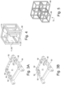
- connection and interconnection system of application EP 1 854 543 reflected in Figs. 1-5 is versatile, it can require multiple custom piece or custom assembly arrangements, such at the two very difference C-clamp patterns shown in Figs. 3A and 3B .
- a modular reactor providing both flexibility and simplicity of interconnection is thus desirable.
- the present invention is defined in the claim.
- microstructure refers to a microfluidic device having internal passages with a characteristic cross-sectional dimension in the few-millimeter to sub-millimeter range. Microstructures may include, for instance, devices similar to and including those disclosed and described in Patent No. US7,007,709 entitled “A Microfluidic Device and Manufacture Thereof,” whether made by the method therein disclosed or other methods.
- Reactor refers to a device for performing chemical or physical processes or combinations thereof, the device including, in the context of this document, two or more microstructures connected for fluid communication therebetween.
- Microstructure module refers to a single microstructure or to two or more microstructures joined together fluidically and mechanically in a stack or other close configuration
- Figs. 6A is a schematic perspective view and Fig. 6B is a side elevation view of a microstructure 11 or microstructure module 12 according to one aspect of the present invention and fitted within a frame 50.
- a microstructure 11 or micro-structure module includes at least a first internal fluid passage (not shown but shown and discussed below in reference to Figs. 12 and 13 ).
- Each microstructure 11 or microstructure module 12 includes an external surface 16 comprising an entrance side 18 and an exit side 20 opposite the entrance side 18.
- Each also has an entrance port 22 extending through the entrance side 18 of the microstructure 11 or microstructure module 12 to the first internal fluid passage, and an exit port (24) extending from the first internal fluid passage through the exit side 20.
- Each microstructure 11 or microstructure module 12 also has a first edge (26) and a second edge (28) opposite the first edge (26), the first and second edges (26, 28) extending from the entrance side (18) to the exit side (20).
- the entrance port (22) and one or more other ports extending through the entrance side (18), such as ports 32a and 32b, generally used for a thermal control fluid, 34a-34d) are arranged in a standard pattern closer to the first edge (26) than the second edge (28), and the entrance port (22) and the exit port (24) are concentric.
- the standard pattern may desirably be a line at a set distance from the first edge 26. Desirably, such line is at a distance of 5 to 30 mm, and includes anywhere from 2 to 10 ports. All ports are desirably in the size range of 1 to 10 mm in diameter, preferably 1.5 to 5 mm, with thermal fluid ports more desirably in the size range of 2 to 5 mm and most desirably from 3 to 5 mm.
- Fig. 6B is a plan view straight toward the first edge 26 of the microstructure 11. From this one edge 26, all of the fluid connecters 30 are directly accessible, as well as the screws 74 by which the associated C-clamps are secured within the frame 50.
- a screw head 76 is also visible in Fig. 6B , which screw head cooperates in supporting the frame on an extended structural support member 40, as will be explained hereafter.
- Figure 6C is a schematic perspective view of a modular reactor in which such an extended structural support member 40 is shown, and on which each of several microstructures or microstructure modules 11a-11j, 12a-12j are independently supported on the extended member 40 by a respective connecting support structure 42 adjustable in at least two linear displacement degrees of freedom 44, 46, one parallel to the direction of the long direction of the extended member 40 and one perpendicular to the long direction of the extended member 40.
- This arrangement allows for easy assembly and easy individual replacement of microstructures or microstructure modules 11a-11j, 12a-12j.
- FIG. 6 Other advantageous aspects of the present invention may also be seen in Fig. 6 .
- the modular reactor 10 of Fig. 6 several microstructures or microstructure modules 11a-j and 12a-j are connected in a single row, such that at least first, second and third microstructure modules (12a-12c, for instance) are each fluidically connected in successive order for fluid communication from one to the next.
- Each of the first, second and third modules also comprise at least a first internal fluid passage 14 (to be shown subsequent-ly), and an external surface 16 comprising an entrance side 18 and an exit side 20 opposite the entrance side 18, with an entrance port 22 extending through the entrance side 18 of the module 12a-12c or microstructure 11a-11c, to the first internal fluid passage (14) and with an exit port (24) extending from the first internal fluid passage (14) through the exit side (20).
- a first edge (26) and a second edge (28) opposite the first edge are labeled in the figure, the first and second edges (26, 28) extending from the entrance side (18) to the exit side (20).
- the entrance port 22 and the exit port 24 are positioned nearer to the first edge 26 of the module 1a-12c than to the second edge 28, and in that the exit side 20 of the first module 12a faces the entrance side 18 of the second module 12b with the exit port 24 of the first module 12a concentric with or offset a specified distance from the entrance port 22 of the second module 12b.
- the exit side 20 of the second module 12b faces the entrance side 18 of the third module 12c with the exit port 24 of the second module 12b concentric with or offset the same specified distance from the entrance port 22 of the third module 12c.
- first edges 26 of the first, second and third modules 12a-12c are aligned, and a first fluid connector 30a extends from the exit port 24 of the first module 12a to the entrance port 22 of the second module 12b, and a second fluid connector 30b extends from the exit port 24 of the second module 12b to the entrance port 22 of the third module 12c.
- microstructures or microstructure modules 11, 12 such as the one shown in diagrammatic cross section in Fig. 12 are preferably used.
- the entrance port 22 through the entrance side 18 of the module joins the first fluidic path 14, which remains mainly in the center of three layers.
- a second fluidic path 36, useful for thermal control fluid, is found in the remaining portion of the outer layers.
- microstructures or microstructure modules 11, 12 such as the one shown in diagrammatic cross section in Fig. 13 are preferably used.
- the entrance port 22 through the entrance side 18 of the module joins the first fluidic path 14, which is able to more easily stay in the center of the three layers, as there is no conflict between the internal volume required for the entrance port 22 and the exit port 24, as there is in the embodiment of Fig. 12 .
- a second fluidic path 36 is found in the portions of the outer layers not used by the first fluidic path 14. With the first edges 26 aligned as in Fig.
- exit ports 24 are aligned with entrance ports 22 but offset by a specified distance 54.
- a fluid path translation of this same amount, the specified distance 54 is built into an alternative fluid connector 30, shown in diagrammatic perspective cross section in Fig. 14 .
- the connector 30 of Fig. 14 thus allows direct, straight fluid connectors 30 to be used between each successive module 12, as long as the specified distance 54 worth of offset is maintained.
- FIGs. 7-9 A few presently preferred arrangements of ports (22, 32a, 32b, 34a-34d are shown in Figs. 7-9 .
- an entrance port 22 shown as a small circle
- an exit port 24 shown as a large dark circle
- Entrance and exit ports 32a, 32b for a second fluid path are desirably both on the same side, here on the front side 18 of the module 12 (which side is facing backward in the figure).
- All of the ports 22, 24, 32a, and 32b are desirably near one edge, designated herein the first edge 26, at least nearer that edge than the second edge 28. Desirably the ports are significantly nearer edge 26 than edge 28, such as two or three times nearer, and possible more.
- Fig. 8 is a schematic partial plan view of another embodiment of a microstructure or microstructure module 11, 12, this time with the entrance side 18 facing front, and having all ports nearer to one edge (the first edge 26) than the other, but in this case with all ports in a specific pattern on a common line 28.
- the line 38 need not be a physical structure, merely geometrical is also intended.
- the embodiment of Fig. 8 adds an additional entrance port 34a into the first internal fluid passage 14 (not shown here).
- port 34a may be a through-port that passes directly through the module or microstructure without entering internal any passages in the module other than the direct line perpendicularly through the microstructure.
- Fig. 9 is a schematic partial plan view of another embodiment of a microstructure or microstructure module 11, 12, similar to that of Fig. 8 , but with multiple additional entrance ports 34a-34d to the first internal fluid passage (not shown here) instead of just one as in Fig. 8 .
- the ports be arranged on a standard distribution.
- One such standard distribution could be the one shown by the common ports between the embodiments of Fig. 8 and Fig. 9 .
- the additional ports of Fig. 9 are on the same line, but do not change the location of the ports corresponding to those on the module of Figure 8 .
- the standard distribution may be grouped at one end of the microstructure or module, or at both ends, or may be spread more or less evenly along the first edge.
- One or more additional exit ports (not shown) from passage 14 through the exit side 20 may also be employed, if desired.
- a microstructure module may be one or multiple microstructures, where the multiple microstructures are joined together fluidically and mechanically in a stack or other close configuration.
- Fig. 10 is a schematic cross sectional view of such a microstructure module 12 comprising multiple microstructures 11a-11e.
- the module 12 includes ports 32a, 32b, 22, 24, that provide fluidic access to the microstructures 11a-11e.
- the microstructures 11a-11e may be joined together mechanically and sealed fluidically by any suitable means, in including gaskets or more permanent means.
- the entrance side surface of the first microstructure 11a then becomes the entrance side 18 of the module 12, while the exit side of the last microstructure 11d similarly becomes the exit side 20 of the module 12, as shown.
- Fig. 11 is a schematic diagram of a reactor system according to an embodiment of the present invention employing microstructures 11 or microstructure modules 12 of different sizes.
- Frames 50 of differing size may hang from the same extended structural support member 40.
- the entrance and exit ports are aligned concentrically despite the different lengths and/or widths of the modules/microstructures 12/11 placed together in the system 10.
- Fig. 15A is a bottom-up diagrammatic plan view
- Fig. 15B is a diagrammatic cross-sectional view, of a portion of the extended structural support member 40 shown in Fig. 6C .
- the support member 40 is in the form of an extruded metal rail 41.
- Mounted on the portion shown of the rail 41 are three orthogonal extruded rail pieces 45, joined to the long rail 41 by individual connecting support structures 42.
- Fig. 16 is a top side diagrammatic perspective view of a connecting support structure 42
- Fig. 17 is a bottom side diagrammatic perspective view of the connecting support structure 42 of Fig. 16
- the structure 42 is fixed rigidly to the associated orthogonal rail piece, with a lower rail-engaging member 49 aligning with the central depression in the associated orthogonal rail 45.
- screw heads (not shown) are left protruding so as to be captured within the channels of the long extruded rail 41, providing secure attachment with freedom to move along the length of the rail 41.
- the large upper rail engaging member aligns with and extends upward into the central slot in the lower side of the rail 41, and assists in preventing binding.
- Fig. 18 is a schematic diagram of another reactor system according to another embodiment of the present invention employing microstructures 11 or microstructure modules 12 of different sizes.
- the entrance and exit ports that are aligned concentrically could reside at the center of the first edge 26 of the modules or microstructures 12, 11.
- Frames 50 of differing size may thus hang from the same extended structural support member 40, but at different heights, as shown.
- the different heights may be optionally be provided by connecting support structures 42 of different thickness, as shown symbolically in Fig. 18 by various vertical cross sections of structures 42.
- FIG. 19 one example of a structure 42 of increased height is shown.
- a support member 40 other than an extruded rail 41 may be used.
- the elongated structural support member 40 is in the form of a rod 39, on which are carried individual linear bearings 43 as part of the respective connecting support structures 42.
- Such an arrangement allows for low friction and ease of moving microstructures or microstructure modules in the direction 44 parallel to the length of the support member 40.
- Such low friction support could also allow a small degree of motion of frames 50 relative to one another during operation of the reactor to accommodate thermal expansion of the straight fluid connectors 30.
- FIG. 21 is a schematic perspective view of a modular reactor including two extended structural support members arranged in parallel and substantially the same height, each with multiple modules or microstructures 12, 11 suspended wherefrom.
- Particularly advantageous in this arrangement is that the first edges of all of the modules or microstructures 12, 11 are facing outward.
- the modules or microstructures 12, 11 may be placed very close together (in the location down the middle of the reactor/system 10 in the figure), while still allowing full access for an assembler, technician, operator, or repair person to adjust, and maintain fluid connections and replace microstructures or modules 11, 12 as desired or needed.
- multiples of these twin rows may be stacked vertically, for a compact reactor footprint.
- Standardization of connection patterns for all different fluidic designs means a reduction of the number of different drilling patterns. Fabrication of different microstructure designs is then more standardized and less difficult.
- product outlet is located concentrically or with a defined offset in front of reactant inlet allows for short and straight connections between two modules or microstructures. This avoids the need to bend tubing for connections and significantly reduces the need for various custom fittings. It is thus easily possible to create straight short connections (interconnections between microstructures or modules) with the use of only materials which can be readily FDA-certified.
- the connector 30 or the entire fluid-contacting portion of the connector 30 can be machined from PTFE or specific grades of PFA.
- the methods of use and/or the devices disclosed herein are generally useful in performing any process that involves mixing, separation, extraction, crystallization, precipitation, or otherwise processing fluids or mixtures of fluids, including multiphase mixtures of fluids-and including fluids or mixtures of fluids including multiphase mixtures of fluids that also contain solids-within a microstructure.
- the processing may include a physical process, a chemical reaction defined as a process that results in the interconversion of organic, inorganic, or both organic and inorganic species, a biochemical process, or any other form of processing.
- the following non-limiting list of reactions may be performed with the disclosed methods and/or devices: oxidation; reduction; substitution; elimination; addition; ligand exchange; metal exchange; and ion exchange.
- reactions of any of the following non-limiting list may be performed with the disclosed methods and/or devices: polymerisation; alkylation; dealkylation; nitration; peroxidation; sulfoxidation; epoxidation; ammoxidation; hydrogenation; dehydrogenation; organometallic reactions; precious metal chemistry/ homogeneous catalyst reactions; carbonylation; thiocarbonylation; alkoxylation; halogenation; dehydrohalogenation; dehalogenation; hydroformylation; carboxylation; decarboxylation; amination; arylation; peptide coupling; aldol condensation; cyclocondensation; dehydrocyclization; esterification; amidation; heterocyclic synthesis; dehydration; alcoholysis; hydrolysis; ammonolysis; etherification; enzymatic synthesis; ketalization; saponification; isomerisation; quaternization; formylation; phase transfer reactions; silylations; nitrile synthesis; phosphoryl
Landscapes
- Chemical & Material Sciences (AREA)
- Chemical Kinetics & Catalysis (AREA)
- Health & Medical Sciences (AREA)
- Organic Chemistry (AREA)
- Dispersion Chemistry (AREA)
- Analytical Chemistry (AREA)
- General Health & Medical Sciences (AREA)
- Hematology (AREA)
- Clinical Laboratory Science (AREA)
- Physical Or Chemical Processes And Apparatus (AREA)
- Micromachines (AREA)
- Apparatus Associated With Microorganisms And Enzymes (AREA)
Description
- The present invention concerns modular microstructured reactors
- Fluidic devices including microstructured features, more particularly glass, glass-ceramic and ceramic microfluidic devices (microstructures), are described in numerous patents, for example in patent applications
DE 199 17 398 ,WO 01/89681 WO 03/026788 WO 03/039736 US patent No. 7,007,709 . - They may be drilled on back or (and) front face(s) to provide inlets and outlets for reactants as well as, typically, thermal fluid inlets and outlets. Specific connection systems have already been described.
- Such connection systems have more particularly been described in patent applications
FR 2 821 657 WO 2005/107 937 (in both documents, multiport connectors with polymer seal are described. A face connection is ensured but it induces a mechanical stress on the microstructure), also in patent applicationEP 1 925 364 (the described connection implies the cooperation of female and male parts) and patent applicationUS 2007/280855 (the connector is here secured to the microreactor via mechanical means (by screw, peg or other fastener)). The applicant has also proposed a specific connection system in patent applicationEP 1 854 543 . Said specific connection system is shown in annexed prior artFigures 1-5 . - As shown in the cross section of
Fig. 1 , according toEP 1 854 543 , fluidic connection at each inlet and outlet is achieved by means of an O-ring 56 constrained in an O-ring groove 58 in afluid connector 30, held against anentrance face 18 of amicrostructure 11 by aadjustable tensioner 60 in the form of a threaded fitting with a grip surface orwrench surface 62 for easy adjustment of tension produced by a threadedjoint 64. a tension or force transmitting member generally in the form of a c-clamp 52 reaches at least partly around bothsides outer surface 16 of themicrostructure 11, so as to be able to press a pad 66 (typically an elastomeric pad) onto thesurface 20 opposite the O-ring 56. Thus forces on themicrostructure 11 due to the compression of the O-ring are limited to compressive forces, well tolerated by glass, glass-ceramics and ceramics, preferred materials formicrostructure 11. - As an alternative to the
pad 66, theopposing surface 20 of themicrostructure 11 may be contacted by another O-ring andfluid connector 30, as shown at the left ofFig. 2 . Individual C-clamps 52 keep shear forces from arising between the O-ring sites. As seen inFigures 3A and 3B , C-clamps 52 are generally secured inframes 50. As shown inFig. 4 ,Frames 50 are then mounted within a largerstructural support frame 68, which mayadditional support beams 70 to optimally position themicrostructures 11. As shown inFig. 5 , larger modular reactors can be built up by combining multiplestructural support frames 68 into aframe assembly 72. - Although the connection and interconnection system of application
EP 1 854 543 reflected inFigs. 1-5 is versatile, it can require multiple custom piece or custom assembly arrangements, such at the two very difference C-clamp patterns shown inFigs. 3A and 3B . A modular reactor providing both flexibility and simplicity of interconnection is thus desirable. - The present invention is defined in the claim.
- The accompanying drawings are included to provide a further understanding of the invention, and are incorporated into and constitute a part of this specification. The drawings illustrate various embodiments of the invention and together with the description serve to explain the principles and operations of the invention.
-
-
Fig. 1 (prior art) is a cross-sectional view of fluidic connection to a microstructure. -
Fig. 2 (prior art) is a cross-sectional view of a further embodiment of a fluidic connection of the type shown inFig. 1 . -
Fig. 3A and 3B (prior art) are schematic perspective views of frames used with fluidic connections of the type shown inFigs. 1 and 2 . -
Fig. 4 (prior art) is a schematic perspective view of a structural frame used with the frames and microstructures ofFigures 1-3 . -
Fig. 5 (prior art) is a schematic perspective view of an assembly of frames of the type shown inFig. 4 . -
Figs. 6A and 6B are schematic perspective views of a microstructure or micro-structure module according to one aspect of the present invention, fitted within a frame. -
Fig. 6C is a schematic perspective view of a modular reactor connected and supported according one or more aspects of the present invention. -
Fig. 7 is a schematic perspective view of a microstructure or microstructure module having all ports nearer to one edge than the other. -
Fig. 8 is a schematic partial plan view of another embodiment of a microstructure or microstructure module having all ports nearer to one edge than the other, with all ports on a common line. -
Fig. 9 is a schematic partial plan view of still another embodiment of a microstructure or microstructure module having all ports nearer to one edge than the other, with all ports on a common line. -
Fig. 10 is a schematic cross sectional view of a microstructure module comprising multiple microstructures. -
Fig. 11 is a schematic diagram of a reactor system according to an embodiment of the presentinvention employing microstructures 11 ormicrostructure modules 12 of different sizes. -
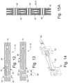
Figs. 12 and 13 are schematic cross sections of microstructures or microstructure modules having differing relative positions of inlet and outlet ports. -
Fig. 14 is a diagrammatic perspective cross section of a fluid connector useful with the microstructure or microstructure module ofFig. 13 . -
Fig. 15A is a bottom-up diagrammatic plan view of a portion of a structural member shown inFig. 6C . -
Fig. 15B is a diagrammatic cross-sectional view of the portion of the structural member shown inFig. 15 . -
Fig. 16 is a top side diagrammatic perspective view of a connecting support structure. -
Fig. 17 is a bottom side diagrammatic perspective view of the connecting support structure ofFig. 16 . -
Fig. 18 is a schematic diagram of another reactor system according to an embodiment of the presentinvention employing microstructures 11 ormicrostructure modules 12 of different sizes. -
Fig. 19 isFig. 16 is a top side diagrammatic perspective view of another connecting support structure. -
Fig. 20 is a schematic perspective view of another embodiment of a modular reactor. -
Fig. 21 is a schematic perspective view of another variation on a modular reactor. - Reference will now be made in detail to the presently preferred embodiments of the invention, examples of which are illustrated in the accompanying drawings. Whenever possible, the same reference numerals will be used throughout the drawings to refer to the same or like parts.
- Within this document, "microstructure" refers to a microfluidic device having internal passages with a characteristic cross-sectional dimension in the few-millimeter to sub-millimeter range. Microstructures may include, for instance, devices similar to and including those disclosed and described in Patent No.
US7,007,709 entitled "A Microfluidic Device and Manufacture Thereof," whether made by the method therein disclosed or other methods. "Reactor" refers to a device for performing chemical or physical processes or combinations thereof, the device including, in the context of this document, two or more microstructures connected for fluid communication therebetween. "Microstructure module" refers to a single microstructure or to two or more microstructures joined together fluidically and mechanically in a stack or other close configuration -
Figures 1-5 (prior art) have been discussed above. -
Figs. 6A is a schematic perspective view andFig. 6B is a side elevation view of amicrostructure 11 ormicrostructure module 12 according to one aspect of the present invention and fitted within aframe 50. In each of the figures amicrostructure 11 or micro-structure module includes at least a first internal fluid passage (not shown but shown and discussed below in reference toFigs. 12 and 13 ). Eachmicrostructure 11 ormicrostructure module 12 includes anexternal surface 16 comprising anentrance side 18 and anexit side 20 opposite theentrance side 18. Each also has anentrance port 22 extending through theentrance side 18 of themicrostructure 11 ormicrostructure module 12 to the first internal fluid passage, and an exit port (24) extending from the first internal fluid passage through theexit side 20. Eachmicrostructure 11 ormicrostructure module 12 also has a first edge (26) and a second edge (28) opposite the first edge (26), the first and second edges (26, 28) extending from the entrance side (18) to the exit side (20). - According to one variation of the present invention, for each of the
microstructures 11, the entrance port (22) and one or more other ports extending through the entrance side (18), such asports first edge 26. Desirably, such line is at a distance of 5 to 30 mm, and includes anywhere from 2 to 10 ports. All ports are desirably in the size range of 1 to 10 mm in diameter, preferably 1.5 to 5 mm, with thermal fluid ports more desirably in the size range of 2 to 5 mm and most desirably from 3 to 5 mm. - With all of the
ports microstructure module Fig. 6B , which is a plan view straight toward thefirst edge 26 of themicrostructure 11. From this oneedge 26, all of thefluid connecters 30 are directly accessible, as well as thescrews 74 by which the associated C-clamps are secured within theframe 50. Ascrew head 76 is also visible inFig. 6B , which screw head cooperates in supporting the frame on an extendedstructural support member 40, as will be explained hereafter. -
Figure 6C is a schematic perspective view of a modular reactor in which such an extendedstructural support member 40 is shown, and on which each of several microstructures ormicrostructure modules 11a-11j, 12a-12j are independently supported on theextended member 40 by a respective connectingsupport structure 42 adjustable in at least two linear displacement degrees offreedom extended member 40 and one perpendicular to the long direction of theextended member 40. This arrangement allows for easy assembly and easy individual replacement of microstructures ormicrostructure modules 11a-11j, 12a-12j. - Other advantageous aspects of the present invention may also be seen in
Fig. 6 . For instance, in themodular reactor 10 ofFig. 6 , several microstructures ormicrostructure modules 11a-j and 12a-j are connected in a single row, such that at least first, second and third microstructure modules (12a-12c, for instance) are each fluidically connected in successive order for fluid communication from one to the next. Each of the first, second and third modules also comprise at least a first internal fluid passage 14 (to be shown subsequent-ly), and anexternal surface 16 comprising anentrance side 18 and anexit side 20 opposite theentrance side 18, with anentrance port 22 extending through theentrance side 18 of themodule 12a-12c ormicrostructure 11a-11c, to the first internal fluid passage (14) and with an exit port (24) extending from the first internal fluid passage (14) through the exit side (20). A first edge (26) and a second edge (28) opposite the first edge are labeled in the figure, the first and second edges (26, 28) extending from the entrance side (18) to the exit side (20). - For each of the first, second and
third modules 12a-12c ormicrostructures 11a-11c, theentrance port 22 and theexit port 24 are positioned nearer to thefirst edge 26 of the module 1a-12c than to thesecond edge 28, and in that theexit side 20 of thefirst module 12a faces theentrance side 18 of thesecond module 12b with theexit port 24 of thefirst module 12a concentric with or offset a specified distance from theentrance port 22 of thesecond module 12b. Similarly, theexit side 20 of thesecond module 12b faces theentrance side 18 of thethird module 12c with theexit port 24 of thesecond module 12b concentric with or offset the same specified distance from theentrance port 22 of thethird module 12c. The first edges 26 of the first, second andthird modules 12a-12c are aligned, and a firstfluid connector 30a extends from theexit port 24 of thefirst module 12a to theentrance port 22 of thesecond module 12b, and a secondfluid connector 30b extends from theexit port 24 of thesecond module 12b to theentrance port 22 of thethird module 12c. - This results in the possibility of many fluidic connections in a row, all well accessible from the side, and all using
standardized fluid connectors 30. Where theexit port 24 of thefirst module 12a is concentric with theentrance port 22 of the second module, microstructures ormicrostructure modules Fig. 12 are preferably used. There, theentrance port 22 through theentrance side 18 of the module joins the firstfluidic path 14, which remains mainly in the center of three layers. A secondfluidic path 36, useful for thermal control fluid, is found in the remaining portion of the outer layers. With the first edges aligned as inFig. 6A , and with edges adjacent to the first also aligned,exit ports 24 are directly aligned to, or concentric with,entrance ports 22. This allows simple, direct, straightfluid connectors 30 to be used between eachmodule 12. - Where the
exit port 24 of thefirst module 12a is offset a specified distance from theentrance port 22 of the second module, microstructures ormicrostructure modules Fig. 13 are preferably used. There, theentrance port 22 through theentrance side 18 of the module joins the firstfluidic path 14, which is able to more easily stay in the center of the three layers, as there is no conflict between the internal volume required for theentrance port 22 and theexit port 24, as there is in the embodiment ofFig. 12 . In the embodiment ofFig. 13 , as inFig. 12 , a secondfluidic path 36, useful for thermal control fluid, is found in the portions of the outer layers not used by the firstfluidic path 14. With thefirst edges 26 aligned as inFig. 6A , and with edges adjacent to thefirst edge 26 also aligned,exit ports 24 are aligned withentrance ports 22 but offset by a specifieddistance 54. A fluid path translation of this same amount, the specifieddistance 54, is built into analternative fluid connector 30, shown in diagrammatic perspective cross section inFig. 14 . Theconnector 30 ofFig. 14 thus allows direct, straightfluid connectors 30 to be used between eachsuccessive module 12, as long as the specifieddistance 54 worth of offset is maintained. - A few presently preferred arrangements of ports (22, 32a, 32b, 34a-34d are shown in
Figs. 7-9 . As explained with reference toFigure 12 , in one presently preferred alternative according to the present invention, depicted in diagrammatic perspective view inFig. 7 , an entrance port 22 (shown as a small circle) and an exit port 24 (shown as a large dark circle) (for a first fluid path 14) are desirably concentric but on opposingsides microstructure module exit ports front side 18 of the module 12 (which side is facing backward in the figure). All of theports first edge 26, at least nearer that edge than thesecond edge 28. Desirably the ports are significantlynearer edge 26 thanedge 28, such as two or three times nearer, and possible more. -
Fig. 8 is a schematic partial plan view of another embodiment of a microstructure ormicrostructure module entrance side 18 facing front, and having all ports nearer to one edge (the first edge 26) than the other, but in this case with all ports in a specific pattern on acommon line 28. (Theline 38 need not be a physical structure, merely geometrical is also intended.) Relative to the ports already shown and discussed inFig. 7 , the embodiment ofFig. 8 adds anadditional entrance port 34a into the first internal fluid passage 14 (not shown here). Alternatively,port 34a may be a through-port that passes directly through the module or microstructure without entering internal any passages in the module other than the direct line perpendicularly through the microstructure. -
Fig. 9 is a schematic partial plan view of another embodiment of a microstructure ormicrostructure module Fig. 8 , but with multipleadditional entrance ports 34a-34d to the first internal fluid passage (not shown here) instead of just one as inFig. 8 . In either embodiment, it is desirably that the ports be arranged on a standard distribution. One such standard distribution could be the one shown by the common ports between the embodiments ofFig. 8 and Fig. 9 . The additional ports ofFig. 9 are on the same line, but do not change the location of the ports corresponding to those on the module ofFigure 8 . The standard distribution may be grouped at one end of the microstructure or module, or at both ends, or may be spread more or less evenly along the first edge. One or more additional exit ports (not shown) frompassage 14 through theexit side 20 may also be employed, if desired. - As defined hereinabove, a microstructure module may be one or multiple microstructures, where the multiple microstructures are joined together fluidically and mechanically in a stack or other close configuration.
Fig. 10 is a schematic cross sectional view of such amicrostructure module 12 comprisingmultiple microstructures 11a-11e. Themodule 12 includesports microstructures 11a-11e. Themicrostructures 11a-11e may be joined together mechanically and sealed fluidically by any suitable means, in including gaskets or more permanent means. The entrance side surface of thefirst microstructure 11a then becomes theentrance side 18 of themodule 12, while the exit side of thelast microstructure 11d similarly becomes theexit side 20 of themodule 12, as shown. -
Fig. 11 is a schematic diagram of a reactor system according to an embodiment of the presentinvention employing microstructures 11 ormicrostructure modules 12 of different sizes.Frames 50 of differing size may hang from the same extendedstructural support member 40. In this embodiment, as suggested by the arrows, the entrance and exit ports are aligned concentrically despite the different lengths and/or widths of the modules/microstructures 12/11 placed together in thesystem 10. -
Fig. 15A is a bottom-up diagrammatic plan view, andFig. 15B is a diagrammatic cross-sectional view, of a portion of the extendedstructural support member 40 shown inFig. 6C . In these embodiments, thesupport member 40 is in the form of an extruded metal rail 41. Mounted on the portion shown of the rail 41 are three orthogonalextruded rail pieces 45, joined to the long rail 41 by individual connectingsupport structures 42. -
Fig. 16 is a top side diagrammatic perspective view of a connectingsupport structure 42, whileFig. 17 is a bottom side diagrammatic perspective view of the connectingsupport structure 42 ofFig. 16 . In use, thestructure 42 is fixed rigidly to the associated orthogonal rail piece, with a lower rail-engagingmember 49 aligning with the central depression in the associatedorthogonal rail 45. At the top of thestructure 42, screw heads (not shown) are left protruding so as to be captured within the channels of the long extruded rail 41, providing secure attachment with freedom to move along the length of the rail 41. Thus arises freedom to move in the direction, or linear displacement degree of freedom, 44, parallel to the length of the extended structural support member 40 (seeFig. 6 for a labeled arrow showing the direction). The large upper rail engaging member aligns with and extends upward into the central slot in the lower side of the rail 41, and assists in preventing binding. -
Fig. 18 is a schematic diagram of another reactor system according to another embodiment of the presentinvention employing microstructures 11 ormicrostructure modules 12 of different sizes. As suggested by the arrows, the entrance and exit ports that are aligned concentrically could reside at the center of thefirst edge 26 of the modules ormicrostructures Frames 50 of differing size may thus hang from the same extendedstructural support member 40, but at different heights, as shown. The different heights may be optionally be provided by connectingsupport structures 42 of different thickness, as shown symbolically inFig. 18 by various vertical cross sections ofstructures 42. In the diagrammatic perspective view ofFig. 19 , one example of astructure 42 of increased height is shown. - Of course a
support member 40 other than an extruded rail 41 may be used. One alternative is shown in themodular reactor 10 ofFigure 20 , in which the elongatedstructural support member 40 is in the form of a rod 39, on which are carried individuallinear bearings 43 as part of the respective connectingsupport structures 42. Such an arrangement allows for low friction and ease of moving microstructures or microstructure modules in thedirection 44 parallel to the length of thesupport member 40. Such low friction support could also allow a small degree of motion offrames 50 relative to one another during operation of the reactor to accommodate thermal expansion of the straightfluid connectors 30. - There are many advantages of the modular reactor the present invention. Some are common to all variants, while others are limited to specific variants. Most of them will be recognized by those of ordinary skill in the art.
- One such advantage may be seen relative to
Figure 21 , which is a schematic perspective view of a modular reactor including two extended structural support members arranged in parallel and substantially the same height, each with multiple modules ormicrostructures microstructures microstructures system 10 in the figure), while still allowing full access for an assembler, technician, operator, or repair person to adjust, and maintain fluid connections and replace microstructures ormodules - Other advantages include, but are not limited to the following.
- Ease of use and troubleshooting is increased. The straightforward layout of the modular reactors of the present invention, with all inlets and outlets visible on a single side of reactor or row
Fig.6C , means that a given reactor is much more easily understood or comprehended. Trouble shooting can be done from a single side, the front side and it is no longer necessary to have access to all four sides of a reactor. The back side of reactor can put against a wall without any problem for maintenance. Putting such a reactor into a hood is quite possible, with few if any constraints. - Assembly time is reduced. Because all microstructures or modules are mounted the same way, and because all connections are implemented the same way, reactor assembly time is significantly reduced.
- Mechanical architecture is simplified and mechanical complexity reduced. Having the same connection pattern for all microstructures, regardless of function, means the same mechanical interface may be used throughout (unlike in Figs. 4a and 4b) and therefore of the number of unique mechanical parts is achieved
- Increased standardization is achieved in microstructure fabrication.
- Standardization of connection patterns for all different fluidic designs means a reduction of the number of different drilling patterns. Fabrication of different microstructure designs is then more standardized and less difficult.
- Short direct connection between microstructures is achieved.
- The fact that product outlet is located concentrically or with a defined offset in front of reactant inlet allows for short and straight connections between two modules or microstructures. This avoids the need to bend tubing for connections and significantly reduces the need for various custom fittings. It is thus easily possible to create straight short connections (interconnections between microstructures or modules) with the use of only materials which can be readily FDA-certified. For example, the
connector 30 or the entire fluid-contacting portion of theconnector 30 can be machined from PTFE or specific grades of PFA. - Compactness is improved. Thanks to product outlet located in same axis or with defined small offset relative to main reactant inlet, it is possible to align all microstructures and having direct short connections, without need to flip microstructures or to translate horizontal some in order to align connections. Benefit for the reactor is higher compactness. (
Fig.6 ) - Unlike in the past, with standard connection patterns it is now convenient to associate, within the same reactor, microstructures of different sizes.
- The methods of use and/or the devices disclosed herein are generally useful in performing any process that involves mixing, separation, extraction, crystallization, precipitation, or otherwise processing fluids or mixtures of fluids, including multiphase mixtures of fluids-and including fluids or mixtures of fluids including multiphase mixtures of fluids that also contain solids-within a microstructure. The processing may include a physical process, a chemical reaction defined as a process that results in the interconversion of organic, inorganic, or both organic and inorganic species, a biochemical process, or any other form of processing. The following non-limiting list of reactions may be performed with the disclosed methods and/or devices: oxidation; reduction; substitution; elimination; addition; ligand exchange; metal exchange; and ion exchange. More specifically, reactions of any of the following non-limiting list may be performed with the disclosed methods and/or devices: polymerisation; alkylation; dealkylation; nitration; peroxidation; sulfoxidation; epoxidation; ammoxidation; hydrogenation; dehydrogenation; organometallic reactions; precious metal chemistry/ homogeneous catalyst reactions; carbonylation; thiocarbonylation; alkoxylation; halogenation; dehydrohalogenation; dehalogenation; hydroformylation; carboxylation; decarboxylation; amination; arylation; peptide coupling; aldol condensation; cyclocondensation; dehydrocyclization; esterification; amidation; heterocyclic synthesis; dehydration; alcoholysis; hydrolysis; ammonolysis; etherification; enzymatic synthesis; ketalization; saponification; isomerisation; quaternization; formylation; phase transfer reactions; silylations; nitrile synthesis; phosphorylation; ozonolysis; azide chemistry; metathesis; hydrosilylation; coupling reactions; and enzymatic reactions.
Claims (1)
- A modular reactor (10) comprising:
at least first, second and third microstructure modules (12a-12c) each fluidically connected in successive order for fluid communication from one to the next, each of the first, second and third modules comprising:at least a first internal fluid passage (14),an external surface (16) comprising an entrance side (18) and an exit side (20) opposite the entrance side (18),an entrance port (22) extending through the entrance side (18) of the module (12a-12c) to the first internal fluid passage (14),an exit port (24) extending from the first internal fluid passage (14) through the exit side (20), anda first edge (26) and a second edge (28) opposite the first edge (26), the first and second edges (26, 28) extending from the entrance side (18) to the exit side (20),wherein, for each of the first, second and third modules (12a-12c), the entrance port (22) and the exit port (24) are positioned nearer to the first edge (26) of the module (12a-12c) than to the second edge (28), and wherein the exit side (20) of the first module (12a) faces the entrance side (18) of the second module (12b) with the exit port (24) concentric with or offset a specified distance from the entrance port (22) of the second module (12b), and wherein the exit side (20) of the second module (12b) faces the entrance side (18) of the third module (12c) with the exit port (24) of the second module (12b) concentric with or offset the specified distance from the entrance port (22) of the third module (12c), and the first edges (26) of the first, second and third modules (12a-12c) are aligned, and a first fluid connector (30a) extends from the exit port (24) of the first module (12a) to the entrance port (22) of the second module (12b), and a second fluid connector (30b) extends from the exit port (24) of the second module (12b) to the entrance port (22) of the third module (12c), andwherein the modular reactor further comprises an extended structural support member (40) and wherein each microstructure module (12a-12j) is independently supported on the extended member (40) by a respective connecting support structure (42) adjustable in at least two linear displacement degrees of freedom (44, 46), one (44) parallel to the direction of the long direction of the extended member (40) and one (46) perpendicular to the long direction of the extended member (40).
Priority Applications (1)
| Application Number | Priority Date | Filing Date | Title |
|---|---|---|---|
| EP10717469.0A EP2429694B1 (en) | 2009-05-11 | 2010-05-11 | Modular reactor |
Applications Claiming Priority (3)
| Application Number | Priority Date | Filing Date | Title |
|---|---|---|---|
| EP09305420 | 2009-05-11 | ||
| EP10717469.0A EP2429694B1 (en) | 2009-05-11 | 2010-05-11 | Modular reactor |
| PCT/US2010/034336 WO2010132412A2 (en) | 2009-05-11 | 2010-05-11 | Modular reactor and system |
Publications (2)
| Publication Number | Publication Date |
|---|---|
| EP2429694A2 EP2429694A2 (en) | 2012-03-21 |
| EP2429694B1 true EP2429694B1 (en) | 2024-04-10 |
Family
ID=43085528
Family Applications (1)
| Application Number | Title | Priority Date | Filing Date |
|---|---|---|---|
| EP10717469.0A Active EP2429694B1 (en) | 2009-05-11 | 2010-05-11 | Modular reactor |
Country Status (8)
| Country | Link |
|---|---|
| US (1) | US9827549B2 (en) |
| EP (1) | EP2429694B1 (en) |
| JP (1) | JP5718905B2 (en) |
| KR (1) | KR101813724B1 (en) |
| CN (1) | CN102421519B (en) |
| SG (1) | SG176002A1 (en) |
| TW (1) | TW201114481A (en) |
| WO (1) | WO2010132412A2 (en) |
Families Citing this family (11)
| Publication number | Priority date | Publication date | Assignee | Title |
|---|---|---|---|---|
| EP2458358B1 (en) | 2010-11-29 | 2017-09-27 | Corning Incorporated | In-line contactless pressure sensors and methods of measuring pressure |
| EP2718004B1 (en) * | 2011-06-07 | 2016-09-21 | Corning Incorporated | Fluidic module suspension system and resulting reactor |
| WO2013066418A1 (en) * | 2011-06-14 | 2013-05-10 | Corning Incorporated | Hybrid microfluidic assemblies |
| AU2015301544A1 (en) | 2014-08-15 | 2017-03-02 | Massachusetts Institute Of Technology | Systems and methods for synthesizing chemical products, including active pharmaceutical ingredients |
| WO2016097045A1 (en) * | 2014-12-17 | 2016-06-23 | Technische Universiteit Eindhoven | Flow distributor for numbering-up micro- and milli- channel reactors |
| CN105964198A (en) * | 2016-04-21 | 2016-09-28 | 常州大学 | Micro reactor with bamboo joint-shaped micro structure |
| CN105749832A (en) * | 2016-04-21 | 2016-07-13 | 常州大学 | Micro-reactor system with pulse diameter-variable microstructure |
| CN105817188A (en) * | 2016-04-21 | 2016-08-03 | 常州大学 | Metal small channel reactor |
| WO2017192595A1 (en) | 2016-05-02 | 2017-11-09 | Massachusetts Institute Of Technology | Reconfigurable multi-step chemical synthesis system and related components and methods |
| WO2018200236A1 (en) | 2017-04-26 | 2018-11-01 | Massachusetts Institute Of Technology | Reconfigurable chemical synthesis systems and methods |
| US11059019B2 (en) * | 2017-10-06 | 2021-07-13 | Corning Incorporated | Flow reactor fluid connection apparatus and method |
Family Cites Families (22)
| Publication number | Priority date | Publication date | Assignee | Title |
|---|---|---|---|---|
| US5580523A (en) * | 1994-04-01 | 1996-12-03 | Bard; Allen J. | Integrated chemical synthesizers |
| DE19746585A1 (en) * | 1997-10-22 | 1999-04-29 | Merck Patent Gmbh | Coupling for micro components with parallel plates |
| DE19917398C2 (en) | 1999-04-16 | 2002-06-20 | Accoris Gmbh | Modular chemical microsystem |
| US6537506B1 (en) | 2000-02-03 | 2003-03-25 | Cellular Process Chemistry, Inc. | Miniaturized reaction apparatus |
| WO2001089681A2 (en) | 2000-05-24 | 2001-11-29 | Cellular Process Chemistry, Inc. | Modular chemical production system incorporating a microreactor |
| US6827095B2 (en) * | 2000-10-12 | 2004-12-07 | Nanostream, Inc. | Modular microfluidic systems |
| FR2821657B1 (en) | 2001-03-01 | 2003-09-26 | Commissariat Energie Atomique | DEVICE FOR THE SEALED AND REVERSIBLE CONNECTION OF CAPILLARIES TO A MICRO-FLUIDIC COMPONENT |
| DE10146545A1 (en) | 2001-09-21 | 2003-04-10 | Merck Patent Gmbh | microcomponent |
| FR2830206B1 (en) | 2001-09-28 | 2004-07-23 | Corning Inc | MICROFLUIDIC DEVICE AND ITS MANUFACTURE |
| DE10155010A1 (en) | 2001-11-06 | 2003-05-15 | Cpc Cellular Process Chemistry | Microreactor system |
| US6743011B2 (en) * | 2001-12-19 | 2004-06-01 | Corning Incorporated | Multi-layer burner module, adapter, and assembly therefor |
| DE10216714A1 (en) | 2002-04-10 | 2004-01-15 | INSTITUT FüR ANGEWANDTE CHEMIE BERLIN-ADLERSHOF E.V. | Modular connection point for facilities of microreaction technology |
| US6832787B1 (en) | 2003-01-24 | 2004-12-21 | Sandia National Laboratories | Edge compression manifold apparatus |
| JP2005224764A (en) * | 2004-02-16 | 2005-08-25 | Fuji Photo Film Co Ltd | Reaction process using microreactor, and microreactor |
| DE102004022423A1 (en) | 2004-05-06 | 2005-12-15 | Siemens Ag | microfluidic |
| EP1679115A1 (en) | 2005-01-07 | 2006-07-12 | Corning Incorporated | High performance microreactor |
| SE530820C2 (en) | 2005-12-22 | 2008-09-16 | Alfa Laval Corp Ab | A mixing system for heat exchangers |
| JP2007247867A (en) * | 2006-03-17 | 2007-09-27 | Olympus Corp | Sliding valve device and microchip equipped with sliding valve device |
| ATE504354T1 (en) | 2006-05-11 | 2011-04-15 | Corning Inc | MODULAR HOLDING AND CONNECTION SYSTEM FOR MICROFLUIDIC DEVICES |
| US7641860B2 (en) | 2006-06-01 | 2010-01-05 | Nanotek, Llc | Modular and reconfigurable multi-stage microreactor cartridge apparatus |
| EP1925364A1 (en) | 2006-11-23 | 2008-05-28 | Nederlandse Organisatie voor Toegepast-Natuuurwetenschappelijk Onderzoek TNO | Multiple microfluidic connector |
| US7919062B2 (en) | 2008-03-20 | 2011-04-05 | Corning Incorporated | Modular microfluidic system and method for building a modular microfludic system |
-
2010
- 2010-05-10 TW TW099114891A patent/TW201114481A/en unknown
- 2010-05-11 JP JP2012510921A patent/JP5718905B2/en not_active Expired - Fee Related
- 2010-05-11 SG SG2011083003A patent/SG176002A1/en unknown
- 2010-05-11 WO PCT/US2010/034336 patent/WO2010132412A2/en not_active Ceased
- 2010-05-11 KR KR1020117029407A patent/KR101813724B1/en active Active
- 2010-05-11 US US13/318,385 patent/US9827549B2/en active Active
- 2010-05-11 CN CN201080021258.XA patent/CN102421519B/en active Active
- 2010-05-11 EP EP10717469.0A patent/EP2429694B1/en active Active
Also Published As
| Publication number | Publication date |
|---|---|
| SG176002A1 (en) | 2011-12-29 |
| KR20120024739A (en) | 2012-03-14 |
| US20120045377A1 (en) | 2012-02-23 |
| WO2010132412A3 (en) | 2011-06-09 |
| EP2429694A2 (en) | 2012-03-21 |
| JP2013526400A (en) | 2013-06-24 |
| JP5718905B2 (en) | 2015-05-13 |
| WO2010132412A2 (en) | 2010-11-18 |
| CN102421519A (en) | 2012-04-18 |
| KR101813724B1 (en) | 2017-12-29 |
| US9827549B2 (en) | 2017-11-28 |
| CN102421519B (en) | 2015-09-09 |
| TW201114481A (en) | 2011-05-01 |
Similar Documents
| Publication | Publication Date | Title |
|---|---|---|
| US9827549B2 (en) | Modular reactor and system | |
| US20120180884A1 (en) | Interconnection of Microfluidic Devices | |
| US7919056B2 (en) | Micro-reactor system | |
| CN101218019B (en) | Flow control through plural, parallel connecting channels to/from a manifold | |
| US20100158763A1 (en) | Microchannel reactors | |
| EP2608877A1 (en) | Micro-fluidic device | |
| US7468165B2 (en) | Microreactor system | |
| EP2714255B1 (en) | Twist flow microfluidic mixer and module | |
| KR20120096403A (en) | Microreactors with connectors sealed thereon ; their manufacturing | |
| US20130206269A1 (en) | Honeycomb-Body-Based Fluidic Interconnectors and Methods | |
| US8303909B2 (en) | Microfluidic assembly | |
| EP2193839A1 (en) | Devices and methods for microreactor fluid distribution | |
| KR102485280B1 (en) | A chemical reactor unit, prefabricated chemical reactor including same, and manufacturing method thereof | |
| US20140369902A1 (en) | Fluidic module permanent stack assemblies and methods |
Legal Events
| Date | Code | Title | Description |
|---|---|---|---|
| PUAI | Public reference made under article 153(3) epc to a published international application that has entered the european phase |
Free format text: ORIGINAL CODE: 0009012 |
|
| 17P | Request for examination filed |
Effective date: 20111108 |
|
| AK | Designated contracting states |
Kind code of ref document: A2 Designated state(s): AL AT BE BG CH CY CZ DE DK EE ES FI FR GB GR HR HU IE IS IT LI LT LU LV MC MK MT NL NO PL PT RO SE SI SK SM TR |
|
| DAX | Request for extension of the european patent (deleted) | ||
| 17Q | First examination report despatched |
Effective date: 20130416 |
|
| STAA | Information on the status of an ep patent application or granted ep patent |
Free format text: STATUS: EXAMINATION IS IN PROGRESS |
|
| GRAP | Despatch of communication of intention to grant a patent |
Free format text: ORIGINAL CODE: EPIDOSNIGR1 |
|
| STAA | Information on the status of an ep patent application or granted ep patent |
Free format text: STATUS: GRANT OF PATENT IS INTENDED |
|
| RIC1 | Information provided on ipc code assigned before grant |
Ipc: B01L 9/00 20060101ALI20230927BHEP Ipc: B01L 3/00 20060101ALI20230927BHEP Ipc: B01J 19/00 20060101AFI20230927BHEP |
|
| INTG | Intention to grant announced |
Effective date: 20231030 |
|
| GRAS | Grant fee paid |
Free format text: ORIGINAL CODE: EPIDOSNIGR3 |
|
| GRAA | (expected) grant |
Free format text: ORIGINAL CODE: 0009210 |
|
| STAA | Information on the status of an ep patent application or granted ep patent |
Free format text: STATUS: THE PATENT HAS BEEN GRANTED |
|
| AK | Designated contracting states |
Kind code of ref document: B1 Designated state(s): AL AT BE BG CH CY CZ DE DK EE ES FI FR GB GR HR HU IE IS IT LI LT LU LV MC MK MT NL NO PL PT RO SE SI SK SM TR |
|
| REG | Reference to a national code |
Ref country code: GB Ref legal event code: FG4D |
|
| REG | Reference to a national code |
Ref country code: CH Ref legal event code: EP |
|
| P01 | Opt-out of the competence of the unified patent court (upc) registered |
Effective date: 20240313 |
|
| REG | Reference to a national code |
Ref country code: DE Ref legal event code: R096 Ref document number: 602010069337 Country of ref document: DE |
|
| REG | Reference to a national code |
Ref country code: IE Ref legal event code: FG4D |
|
| REG | Reference to a national code |
Ref country code: LT Ref legal event code: MG9D |
|
| REG | Reference to a national code |
Ref country code: NL Ref legal event code: MP Effective date: 20240410 |
|
| REG | Reference to a national code |
Ref country code: AT Ref legal event code: MK05 Ref document number: 1674367 Country of ref document: AT Kind code of ref document: T Effective date: 20240410 |
|
| PG25 | Lapsed in a contracting state [announced via postgrant information from national office to epo] |
Ref country code: NL Free format text: LAPSE BECAUSE OF FAILURE TO SUBMIT A TRANSLATION OF THE DESCRIPTION OR TO PAY THE FEE WITHIN THE PRESCRIBED TIME-LIMIT Effective date: 20240410 |
|
| PG25 | Lapsed in a contracting state [announced via postgrant information from national office to epo] |
Ref country code: NL Free format text: LAPSE BECAUSE OF FAILURE TO SUBMIT A TRANSLATION OF THE DESCRIPTION OR TO PAY THE FEE WITHIN THE PRESCRIBED TIME-LIMIT Effective date: 20240410 |
|
| PG25 | Lapsed in a contracting state [announced via postgrant information from national office to epo] |
Ref country code: IS Free format text: LAPSE BECAUSE OF FAILURE TO SUBMIT A TRANSLATION OF THE DESCRIPTION OR TO PAY THE FEE WITHIN THE PRESCRIBED TIME-LIMIT Effective date: 20240810 |
|
| PG25 | Lapsed in a contracting state [announced via postgrant information from national office to epo] |
Ref country code: BG Free format text: LAPSE BECAUSE OF FAILURE TO SUBMIT A TRANSLATION OF THE DESCRIPTION OR TO PAY THE FEE WITHIN THE PRESCRIBED TIME-LIMIT Effective date: 20240410 |
|
| PG25 | Lapsed in a contracting state [announced via postgrant information from national office to epo] |
Ref country code: HR Free format text: LAPSE BECAUSE OF FAILURE TO SUBMIT A TRANSLATION OF THE DESCRIPTION OR TO PAY THE FEE WITHIN THE PRESCRIBED TIME-LIMIT Effective date: 20240410 Ref country code: FI Free format text: LAPSE BECAUSE OF FAILURE TO SUBMIT A TRANSLATION OF THE DESCRIPTION OR TO PAY THE FEE WITHIN THE PRESCRIBED TIME-LIMIT Effective date: 20240410 |
|
| PG25 | Lapsed in a contracting state [announced via postgrant information from national office to epo] |
Ref country code: GR Free format text: LAPSE BECAUSE OF FAILURE TO SUBMIT A TRANSLATION OF THE DESCRIPTION OR TO PAY THE FEE WITHIN THE PRESCRIBED TIME-LIMIT Effective date: 20240711 |
|
| PG25 | Lapsed in a contracting state [announced via postgrant information from national office to epo] |
Ref country code: PT Free format text: LAPSE BECAUSE OF FAILURE TO SUBMIT A TRANSLATION OF THE DESCRIPTION OR TO PAY THE FEE WITHIN THE PRESCRIBED TIME-LIMIT Effective date: 20240812 |
|
| PG25 | Lapsed in a contracting state [announced via postgrant information from national office to epo] |
Ref country code: ES Free format text: LAPSE BECAUSE OF FAILURE TO SUBMIT A TRANSLATION OF THE DESCRIPTION OR TO PAY THE FEE WITHIN THE PRESCRIBED TIME-LIMIT Effective date: 20240410 |
|
| PG25 | Lapsed in a contracting state [announced via postgrant information from national office to epo] |
Ref country code: AT Free format text: LAPSE BECAUSE OF FAILURE TO SUBMIT A TRANSLATION OF THE DESCRIPTION OR TO PAY THE FEE WITHIN THE PRESCRIBED TIME-LIMIT Effective date: 20240410 |
|
| PG25 | Lapsed in a contracting state [announced via postgrant information from national office to epo] |
Ref country code: PL Free format text: LAPSE BECAUSE OF FAILURE TO SUBMIT A TRANSLATION OF THE DESCRIPTION OR TO PAY THE FEE WITHIN THE PRESCRIBED TIME-LIMIT Effective date: 20240410 |
|
| PG25 | Lapsed in a contracting state [announced via postgrant information from national office to epo] |
Ref country code: LV Free format text: LAPSE BECAUSE OF FAILURE TO SUBMIT A TRANSLATION OF THE DESCRIPTION OR TO PAY THE FEE WITHIN THE PRESCRIBED TIME-LIMIT Effective date: 20240410 |
|
| PG25 | Lapsed in a contracting state [announced via postgrant information from national office to epo] |
Ref country code: PT Free format text: LAPSE BECAUSE OF FAILURE TO SUBMIT A TRANSLATION OF THE DESCRIPTION OR TO PAY THE FEE WITHIN THE PRESCRIBED TIME-LIMIT Effective date: 20240812 Ref country code: PL Free format text: LAPSE BECAUSE OF FAILURE TO SUBMIT A TRANSLATION OF THE DESCRIPTION OR TO PAY THE FEE WITHIN THE PRESCRIBED TIME-LIMIT Effective date: 20240410 Ref country code: NO Free format text: LAPSE BECAUSE OF FAILURE TO SUBMIT A TRANSLATION OF THE DESCRIPTION OR TO PAY THE FEE WITHIN THE PRESCRIBED TIME-LIMIT Effective date: 20240710 Ref country code: LV Free format text: LAPSE BECAUSE OF FAILURE TO SUBMIT A TRANSLATION OF THE DESCRIPTION OR TO PAY THE FEE WITHIN THE PRESCRIBED TIME-LIMIT Effective date: 20240410 Ref country code: IS Free format text: LAPSE BECAUSE OF FAILURE TO SUBMIT A TRANSLATION OF THE DESCRIPTION OR TO PAY THE FEE WITHIN THE PRESCRIBED TIME-LIMIT Effective date: 20240810 Ref country code: HR Free format text: LAPSE BECAUSE OF FAILURE TO SUBMIT A TRANSLATION OF THE DESCRIPTION OR TO PAY THE FEE WITHIN THE PRESCRIBED TIME-LIMIT Effective date: 20240410 Ref country code: GR Free format text: LAPSE BECAUSE OF FAILURE TO SUBMIT A TRANSLATION OF THE DESCRIPTION OR TO PAY THE FEE WITHIN THE PRESCRIBED TIME-LIMIT Effective date: 20240711 Ref country code: FI Free format text: LAPSE BECAUSE OF FAILURE TO SUBMIT A TRANSLATION OF THE DESCRIPTION OR TO PAY THE FEE WITHIN THE PRESCRIBED TIME-LIMIT Effective date: 20240410 Ref country code: ES Free format text: LAPSE BECAUSE OF FAILURE TO SUBMIT A TRANSLATION OF THE DESCRIPTION OR TO PAY THE FEE WITHIN THE PRESCRIBED TIME-LIMIT Effective date: 20240410 Ref country code: BG Free format text: LAPSE BECAUSE OF FAILURE TO SUBMIT A TRANSLATION OF THE DESCRIPTION OR TO PAY THE FEE WITHIN THE PRESCRIBED TIME-LIMIT Effective date: 20240410 Ref country code: AT Free format text: LAPSE BECAUSE OF FAILURE TO SUBMIT A TRANSLATION OF THE DESCRIPTION OR TO PAY THE FEE WITHIN THE PRESCRIBED TIME-LIMIT Effective date: 20240410 |
|
| REG | Reference to a national code |
Ref country code: DE Ref legal event code: R119 Ref document number: 602010069337 Country of ref document: DE |
|
| REG | Reference to a national code |
Ref country code: CH Ref legal event code: PL |
|
| PG25 | Lapsed in a contracting state [announced via postgrant information from national office to epo] |
Ref country code: DK Free format text: LAPSE BECAUSE OF FAILURE TO SUBMIT A TRANSLATION OF THE DESCRIPTION OR TO PAY THE FEE WITHIN THE PRESCRIBED TIME-LIMIT Effective date: 20240410 |
|
| PG25 | Lapsed in a contracting state [announced via postgrant information from national office to epo] |
Ref country code: LU Free format text: LAPSE BECAUSE OF NON-PAYMENT OF DUE FEES Effective date: 20240511 |
|
| PG25 | Lapsed in a contracting state [announced via postgrant information from national office to epo] |
Ref country code: EE Free format text: LAPSE BECAUSE OF FAILURE TO SUBMIT A TRANSLATION OF THE DESCRIPTION OR TO PAY THE FEE WITHIN THE PRESCRIBED TIME-LIMIT Effective date: 20240410 |
|
| PG25 | Lapsed in a contracting state [announced via postgrant information from national office to epo] |
Ref country code: CZ Free format text: LAPSE BECAUSE OF FAILURE TO SUBMIT A TRANSLATION OF THE DESCRIPTION OR TO PAY THE FEE WITHIN THE PRESCRIBED TIME-LIMIT Effective date: 20240410 |
|
| PG25 | Lapsed in a contracting state [announced via postgrant information from national office to epo] |
Ref country code: SK Free format text: LAPSE BECAUSE OF FAILURE TO SUBMIT A TRANSLATION OF THE DESCRIPTION OR TO PAY THE FEE WITHIN THE PRESCRIBED TIME-LIMIT Effective date: 20240410 Ref country code: RO Free format text: LAPSE BECAUSE OF FAILURE TO SUBMIT A TRANSLATION OF THE DESCRIPTION OR TO PAY THE FEE WITHIN THE PRESCRIBED TIME-LIMIT Effective date: 20240410 |
|
| PG25 | Lapsed in a contracting state [announced via postgrant information from national office to epo] |
Ref country code: SM Free format text: LAPSE BECAUSE OF FAILURE TO SUBMIT A TRANSLATION OF THE DESCRIPTION OR TO PAY THE FEE WITHIN THE PRESCRIBED TIME-LIMIT Effective date: 20240410 |
|
| PG25 | Lapsed in a contracting state [announced via postgrant information from national office to epo] |
Ref country code: SM Free format text: LAPSE BECAUSE OF FAILURE TO SUBMIT A TRANSLATION OF THE DESCRIPTION OR TO PAY THE FEE WITHIN THE PRESCRIBED TIME-LIMIT Effective date: 20240410 Ref country code: SK Free format text: LAPSE BECAUSE OF FAILURE TO SUBMIT A TRANSLATION OF THE DESCRIPTION OR TO PAY THE FEE WITHIN THE PRESCRIBED TIME-LIMIT Effective date: 20240410 Ref country code: RO Free format text: LAPSE BECAUSE OF FAILURE TO SUBMIT A TRANSLATION OF THE DESCRIPTION OR TO PAY THE FEE WITHIN THE PRESCRIBED TIME-LIMIT Effective date: 20240410 Ref country code: LU Free format text: LAPSE BECAUSE OF NON-PAYMENT OF DUE FEES Effective date: 20240511 Ref country code: EE Free format text: LAPSE BECAUSE OF FAILURE TO SUBMIT A TRANSLATION OF THE DESCRIPTION OR TO PAY THE FEE WITHIN THE PRESCRIBED TIME-LIMIT Effective date: 20240410 Ref country code: DK Free format text: LAPSE BECAUSE OF FAILURE TO SUBMIT A TRANSLATION OF THE DESCRIPTION OR TO PAY THE FEE WITHIN THE PRESCRIBED TIME-LIMIT Effective date: 20240410 Ref country code: CZ Free format text: LAPSE BECAUSE OF FAILURE TO SUBMIT A TRANSLATION OF THE DESCRIPTION OR TO PAY THE FEE WITHIN THE PRESCRIBED TIME-LIMIT Effective date: 20240410 Ref country code: CH Free format text: LAPSE BECAUSE OF NON-PAYMENT OF DUE FEES Effective date: 20240531 Ref country code: MC Free format text: LAPSE BECAUSE OF FAILURE TO SUBMIT A TRANSLATION OF THE DESCRIPTION OR TO PAY THE FEE WITHIN THE PRESCRIBED TIME-LIMIT Effective date: 20240410 |
|
| PG25 | Lapsed in a contracting state [announced via postgrant information from national office to epo] |
Ref country code: IT Free format text: LAPSE BECAUSE OF FAILURE TO SUBMIT A TRANSLATION OF THE DESCRIPTION OR TO PAY THE FEE WITHIN THE PRESCRIBED TIME-LIMIT Effective date: 20240410 |
|
| PLBE | No opposition filed within time limit |
Free format text: ORIGINAL CODE: 0009261 |
|
| STAA | Information on the status of an ep patent application or granted ep patent |
Free format text: STATUS: NO OPPOSITION FILED WITHIN TIME LIMIT |
|
| REG | Reference to a national code |
Ref country code: BE Ref legal event code: MM Effective date: 20240531 |
|
| 26N | No opposition filed |
Effective date: 20250113 |
|
| GBPC | Gb: european patent ceased through non-payment of renewal fee |
Effective date: 20240710 |
|
| PG25 | Lapsed in a contracting state [announced via postgrant information from national office to epo] |
Ref country code: DE Free format text: LAPSE BECAUSE OF NON-PAYMENT OF DUE FEES Effective date: 20241203 |
|
| PG25 | Lapsed in a contracting state [announced via postgrant information from national office to epo] |
Ref country code: IE Free format text: LAPSE BECAUSE OF NON-PAYMENT OF DUE FEES Effective date: 20240511 |
|
| PG25 | Lapsed in a contracting state [announced via postgrant information from national office to epo] |
Ref country code: SI Free format text: LAPSE BECAUSE OF FAILURE TO SUBMIT A TRANSLATION OF THE DESCRIPTION OR TO PAY THE FEE WITHIN THE PRESCRIBED TIME-LIMIT Effective date: 20240410 Ref country code: BE Free format text: LAPSE BECAUSE OF NON-PAYMENT OF DUE FEES Effective date: 20240531 |
|
| PG25 | Lapsed in a contracting state [announced via postgrant information from national office to epo] |
Ref country code: GB Free format text: LAPSE BECAUSE OF NON-PAYMENT OF DUE FEES Effective date: 20240710 |
|
| PGFP | Annual fee paid to national office [announced via postgrant information from national office to epo] |
Ref country code: FR Payment date: 20250409 Year of fee payment: 16 |
|
| PG25 | Lapsed in a contracting state [announced via postgrant information from national office to epo] |
Ref country code: CY Free format text: LAPSE BECAUSE OF FAILURE TO SUBMIT A TRANSLATION OF THE DESCRIPTION OR TO PAY THE FEE WITHIN THE PRESCRIBED TIME-LIMIT; INVALID AB INITIO Effective date: 20100511 |
|
| PG25 | Lapsed in a contracting state [announced via postgrant information from national office to epo] |
Ref country code: HU Free format text: LAPSE BECAUSE OF FAILURE TO SUBMIT A TRANSLATION OF THE DESCRIPTION OR TO PAY THE FEE WITHIN THE PRESCRIBED TIME-LIMIT; INVALID AB INITIO Effective date: 20100511 |
|
| PG25 | Lapsed in a contracting state [announced via postgrant information from national office to epo] |
Ref country code: SE Free format text: LAPSE BECAUSE OF FAILURE TO SUBMIT A TRANSLATION OF THE DESCRIPTION OR TO PAY THE FEE WITHIN THE PRESCRIBED TIME-LIMIT Effective date: 20240410 |