EP2429260A2 - Heating module - Google Patents
Heating module Download PDFInfo
- Publication number
- EP2429260A2 EP2429260A2 EP11180321A EP11180321A EP2429260A2 EP 2429260 A2 EP2429260 A2 EP 2429260A2 EP 11180321 A EP11180321 A EP 11180321A EP 11180321 A EP11180321 A EP 11180321A EP 2429260 A2 EP2429260 A2 EP 2429260A2
- Authority
- EP
- European Patent Office
- Prior art keywords
- wire
- heating module
- region
- plate
- magnetic
- Prior art date
- Legal status (The legal status is an assumption and is not a legal conclusion. Google has not performed a legal analysis and makes no representation as to the accuracy of the status listed.)
- Withdrawn
Links
- 238000010438 heat treatment Methods 0.000 title claims abstract description 49
- 238000004804 winding Methods 0.000 claims abstract description 42
- 230000006698 induction Effects 0.000 claims abstract description 36
- 239000000853 adhesive Substances 0.000 claims description 4
- 230000001070 adhesive effect Effects 0.000 claims description 4
- 239000011810 insulating material Substances 0.000 claims description 4
- 238000010586 diagram Methods 0.000 description 2
- 238000012986 modification Methods 0.000 description 2
- 230000004048 modification Effects 0.000 description 2
- 229910000859 α-Fe Inorganic materials 0.000 description 2
- 230000003213 activating effect Effects 0.000 description 1
- 230000000694 effects Effects 0.000 description 1
- 239000002184 metal Substances 0.000 description 1
- 238000003466 welding Methods 0.000 description 1
Images




Classifications
-
- H—ELECTRICITY
- H05—ELECTRIC TECHNIQUES NOT OTHERWISE PROVIDED FOR
- H05B—ELECTRIC HEATING; ELECTRIC LIGHT SOURCES NOT OTHERWISE PROVIDED FOR; CIRCUIT ARRANGEMENTS FOR ELECTRIC LIGHT SOURCES, IN GENERAL
- H05B6/00—Heating by electric, magnetic or electromagnetic fields
- H05B6/02—Induction heating
- H05B6/10—Induction heating apparatus, other than furnaces, for specific applications
- H05B6/12—Cooking devices
- H05B6/1209—Cooking devices induction cooking plates or the like and devices to be used in combination with them
- H05B6/1245—Cooking devices induction cooking plates or the like and devices to be used in combination with them with special coil arrangements
- H05B6/1254—Cooking devices induction cooking plates or the like and devices to be used in combination with them with special coil arrangements using conductive pieces to direct the induced magnetic field
-
- H—ELECTRICITY
- H05—ELECTRIC TECHNIQUES NOT OTHERWISE PROVIDED FOR
- H05B—ELECTRIC HEATING; ELECTRIC LIGHT SOURCES NOT OTHERWISE PROVIDED FOR; CIRCUIT ARRANGEMENTS FOR ELECTRIC LIGHT SOURCES, IN GENERAL
- H05B6/00—Heating by electric, magnetic or electromagnetic fields
- H05B6/02—Induction heating
- H05B6/10—Induction heating apparatus, other than furnaces, for specific applications
- H05B6/12—Cooking devices
- H05B6/1209—Cooking devices induction cooking plates or the like and devices to be used in combination with them
- H05B6/1245—Cooking devices induction cooking plates or the like and devices to be used in combination with them with special coil arrangements
- H05B6/1272—Cooking devices induction cooking plates or the like and devices to be used in combination with them with special coil arrangements with more than one coil or coil segment per heating zone
-
- H—ELECTRICITY
- H05—ELECTRIC TECHNIQUES NOT OTHERWISE PROVIDED FOR
- H05B—ELECTRIC HEATING; ELECTRIC LIGHT SOURCES NOT OTHERWISE PROVIDED FOR; CIRCUIT ARRANGEMENTS FOR ELECTRIC LIGHT SOURCES, IN GENERAL
- H05B2206/00—Aspects relating to heating by electric, magnetic, or electromagnetic fields covered by group H05B6/00
- H05B2206/02—Induction heating
- H05B2206/022—Special supports for the induction coils
-
- Y—GENERAL TAGGING OF NEW TECHNOLOGICAL DEVELOPMENTS; GENERAL TAGGING OF CROSS-SECTIONAL TECHNOLOGIES SPANNING OVER SEVERAL SECTIONS OF THE IPC; TECHNICAL SUBJECTS COVERED BY FORMER USPC CROSS-REFERENCE ART COLLECTIONS [XRACs] AND DIGESTS
- Y02—TECHNOLOGIES OR APPLICATIONS FOR MITIGATION OR ADAPTATION AGAINST CLIMATE CHANGE
- Y02B—CLIMATE CHANGE MITIGATION TECHNOLOGIES RELATED TO BUILDINGS, e.g. HOUSING, HOUSE APPLIANCES OR RELATED END-USER APPLICATIONS
- Y02B40/00—Technologies aiming at improving the efficiency of home appliances, e.g. induction cooking or efficient technologies for refrigerators, freezers or dish washers
Definitions
- This application relates in general to a heating module and in particular to a heating module disposed in an induction cooker.
- a conventional coil module 100 of an induction cooker includes a wire 110, a plate 120, and a ferrite core unit 130.
- the wire 110 may be a litz wire, and the plate 120 is made of insulating material, wherein the wire 110 is spirally disposed on the plate 120.
- the ferrite core unit 130 includes several longitudinal magnetic cores 131 which are disposed beneath the plate 120.
- the spiral configuration of the wire 110 may cause a concentration of eddy current at the center of the pot such that heating of the pot is uneven.
- the coil module 100 usually requires more power for heating the pot, thereby resulting in inefficient power consumption.
- the conventional induction cooker may not be suitable for large pots as the closed contact configuration of the wire 110 restricts the diameter of the heater.
- the pot adapted for the conventional induction cooker is uneasy to be selected.
- An object of the present invention is to provide a heating module, wherein the heating module is disposed in an induction cooker and includes a magnetic induction unit, a plate disposed on the magnetic induction unit, and a wire horizontally and spirally disposed on the plate.
- the wire In a first region, the wire is spirally wound with a gap between two adjacent windings. Preferably, the gap is ranged from 0.5 mm to 4 mm.
- the wire is spirally and tightly wound into a close contact shape, wherein the second region is on an outer side of the first region.
- Another object of the present invention is to provide a heating module including a magnetic induction unit, a plate coupled to the magnetic induction unit, and a wire disposed on the plate and wound with different winding densities at the same plane.
- the winding density of the wire is gradually increased from an inner side to an outer side of the heating module.
- the winding density of the wire is gradually increased from an inner side to an outer side of the heating module.
- the wire is spirally and horizontally disposed on the plate, and an average winding density of the wire in a first region is less than that in a second region, wherein the second region is on an outer side of the first region.
- the heating module is disposed in an induction cooker, and the magnetic induction unit comprises a plurality of magnetic cores.
- Another further object of the present invention is to provide a heating module disposed in an induction cooker, and including a magnetic induction unit having a plurality of magnetic cores, a plate disposed on the magnetic cores, and a wire disposed on the plate, wherein an average winding density of the wire in a first region is less than that in a second region.
- the winding number of the wire in the first region equals to or exceeds half of a total winding number of the wire.
- the winding number of the wire in the second region is less than or equal to half of a total winding number of the wire.
- winding number of the wire in the second region equals to or exceeds 3.
- the magnetic induction unit comprises 5 to 8 magnetic cores
- the wire is a litz wire
- the plate is made of insulating material.
- the magnetic cores have a longitudinal structure and are arranged in a radial pattern.
- each of the magnetic cores has a first protrusion, a second protrusion, and a recess formed between the first and second protrusions, wherein the first and second protrusions are formed at opposite ends of the magnetic core.
- each of the magnetic cores further has a first segment, a second segment, and a third segment, the second segment connects the first segment with the third segment, and the first and second protrusions are respectively formed on the first and third segments.
- the magnetic induction unit is assembled with the plate by engagement or connected to the plate by an adhesive.
- FIG. 1 is an exploded view of a conventional coil module in an induction cooker
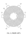
- FIG. 2 is a top view of a conventional coil module
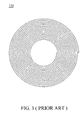
- FIG. 3 is a schematic diagram of a wire shown in FIG. 2 ;
- FIG. 4 is an exploded view of a heating module according to an embodiment of the invention.
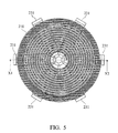
- FIG. 5 is a top view of a heating module according to an embodiment of the invention.
- FIG. 6 is a schematic diagram of a wire shown in FIG. 5 ;
- FIG. 7 is a sectional view of FIG. 5 along the line X1-X2;
- FIG. 8 is a perspective view of a magnetic core shown in FIG. 4 ;
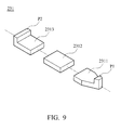
- FIG. 9 is an exploded view of a magnetic core according to another embodiment of the invention.
- a heating module 200 is used in an induction cooker and includes a wire 210, a plate 220, and a magnetic induction unit 230 disposed beneath the plate 220 according to an embodiment of the present invention.
- the wire 210 can be a litz wire
- the plate 220 is made of insulating material, wherein the wire 210 is horizontally and spirally disposed on the plate 220.
- the magnetic induction unit 230 includes a plurality of longitudinal magnetic cores 231 (about 5 ⁇ 8 cores) arranged in a radial pattern for sustaining the wire 210 and the plate 220.
- the magnetic induction unit 230 can be assembled with the plate 220 by engagement or fixed to the plate 220 by an adhesive.
- the wire 210 in this embodiment is spirally wound from the inside toward the outside of the heating module 200 in different winding densities.
- the flat and spirally wound wire 210 has a first region R1 and a second region R2, wherein the second region R2 is at an outer side of the first region R1.
- the wire 210 is spirally wound with a gap between two adjacent windings.
- a preferable range of the gap is from 0.5mm to 4.0mm.
- the wire 210 is tightly wound into a close contact shape without any gap between adjacent windings. Via the different winding densities of the wire 210, uneven heating of the pot can be prevented so as to improve efficiency of the heating module 200.
- N represents the total winding number of the wire 210
- N1 represents the winding number of the wire 210 in the first region R1
- the winding number N1 of the wire 210 in the first region R1 equals to or exceeds half of the total winding number N of the wire 210 (N1 ⁇ N/2).
- the winding number N2 of the wire 210 in the second region R2 is less than or equal to half of the total winding number N of the wire 210 (N2 ⁇ N/2).
- the winding number N2 is equal to or exceeds 3, i.e. 3 ⁇ N2 ⁇ N/2, so as to eliminate uneven heating effect between the inner and outer sides of the heating module 200.
- the winding density of the wire 210 can be gradually increased from the inner side to the outer side of the heating module 200.
- the average winding density of the wire 210 in the first region R1 is less than that in the second region R2, wherein the second region R2 is at the outer side of the first region R1 as shown in FIGs. 6 and 7 .
- each magnetic core 231 of the magnetic induction unit 230 forms a first protrusion P1, a second protrusion P2, and a recess 2310 between the first and second protrusions P1 and P2.
- the wire 210 can be received in the recess 2310, as shown in FIG. 7 .
- the first and second protrusions P1 and P2 can enhance the closed magnetic field and Eddy Current so as to reduce power consumption and improve efficiency of the heating module 200.
- FIG. 7 also shows that the flat wound wires 210 in the first and second regions R1 and R2 are wound on the same plane.
- the magnetic core 231 can be formed as a single piece or constructed by several parts.
- FIG. 9 illustrates another embodiment of a magnetic core 231 which includes a first segment 2311, a second segment 2312, and a third segment 2313.
- the second segment 2312 connects the first segment 2311 with the third segment 2313, wherein the first and second protrusions P1 and P2 are respectively formed on the first and third segments 2311 and 2313.
- the first segment 2311, second segment 2312, and third segment 2313 can be fixed to each other by welding or adhesive for magnetic conduction.
- the invention provides a heating module which can be widely applied to induction cookers.
- the heating module includes a flat and spirally wound wire with different winding densities to prevent uneven heating between the inner and outer sides of the heating module.
- the heating module of the invention can provide a larger heating surface than the conventional induction cookers due to the different winding densities of the wire.
- the invention can be more suitable for large pots even when the pots are not precisely positioned at the center of the induction cooker.
Landscapes
- Physics & Mathematics (AREA)
- Electromagnetism (AREA)
- Induction Heating Cooking Devices (AREA)
- General Induction Heating (AREA)
Abstract
Description
- This Application claims priority of Taiwan Patent Application No.
099130252, filed on Sep. 8, 2010 - This application relates in general to a heating module and in particular to a heating module disposed in an induction cooker.
- In an induction cooker, an electrical current can be applied to a coil to create a magnetic field. This magnetic field induces an Eddy current in a metal pot to heat food. Referring to
FIGs. 1-3 , aconventional coil module 100 of an induction cooker includes awire 110, aplate 120, and aferrite core unit 130. Thewire 110 may be a litz wire, and theplate 120 is made of insulating material, wherein thewire 110 is spirally disposed on theplate 120. As shown inFIGs. 1 and2 , theferrite core unit 130 includes several longitudinalmagnetic cores 131 which are disposed beneath theplate 120. - When activating the
coil module 100 at the same power condition, the spiral configuration of thewire 110 may cause a concentration of eddy current at the center of the pot such that heating of the pot is uneven. Thus, thecoil module 100 usually requires more power for heating the pot, thereby resulting in inefficient power consumption. Additionally, the conventional induction cooker may not be suitable for large pots as the closed contact configuration of thewire 110 restricts the diameter of the heater. In addition to the disadvantages of poor heating efficiency and uneven heating, the pot adapted for the conventional induction cooker is uneasy to be selected. - An object of the present invention is to provide a heating module, wherein the heating module is disposed in an induction cooker and includes a magnetic induction unit, a plate disposed on the magnetic induction unit, and a wire horizontally and spirally disposed on the plate. In a first region, the wire is spirally wound with a gap between two adjacent windings. Preferably, the gap is ranged from 0.5 mm to 4 mm. In a second region, the wire is spirally and tightly wound into a close contact shape, wherein the second region is on an outer side of the first region.
- Another object of the present invention is to provide a heating module including a magnetic induction unit, a plate coupled to the magnetic induction unit, and a wire disposed on the plate and wound with different winding densities at the same plane.
- Preferably, the winding density of the wire is gradually increased from an inner side to an outer side of the heating module.
- Preferably, the winding density of the wire is gradually increased from an inner side to an outer side of the heating module.
- Preferably, the wire is spirally and horizontally disposed on the plate, and an average winding density of the wire in a first region is less than that in a second region, wherein the second region is on an outer side of the first region.
- Preferably, wherein the heating module is disposed in an induction cooker, and the magnetic induction unit comprises a plurality of magnetic cores.
- Another further object of the present invention is to provide a heating module disposed in an induction cooker, and including a magnetic induction unit having a plurality of magnetic cores, a plate disposed on the magnetic cores, and a wire disposed on the plate, wherein an average winding density of the wire in a first region is less than that in a second region.
- Preferably, wherein the winding number of the wire in the first region equals to or exceeds half of a total winding number of the wire.
- Preferably, wherein the winding number of the wire in the second region is less than or equal to half of a total winding number of the wire.
- Preferably, wherein the winding number of the wire in the second region equals to or exceeds 3.
- Preferably, wherein the magnetic induction unit comprises 5 to 8 magnetic cores, the wire is a litz wire, and the plate is made of insulating material.
- Preferably, wherein the magnetic cores have a longitudinal structure and are arranged in a radial pattern.
- Preferably, wherein each of the magnetic cores has a first protrusion, a second protrusion, and a recess formed between the first and second protrusions, wherein the first and second protrusions are formed at opposite ends of the magnetic core.
- Preferably, each of the magnetic cores further has a first segment, a second segment, and a third segment, the second segment connects the first segment with the third segment, and the first and second protrusions are respectively formed on the first and third segments.
- Preferably, wherein the magnetic induction unit is assembled with the plate by engagement or connected to the plate by an adhesive.
- The invention can be more fully understood by reading the subsequent detailed description and examples with references made to the accompanying drawings, wherein:
-
FIG. 1 is an exploded view of a conventional coil module in an induction cooker; -
FIG. 2 is a top view of a conventional coil module; -
FIG. 3 is a schematic diagram of a wire shown inFIG. 2 ; -
FIG. 4 is an exploded view of a heating module according to an embodiment of the invention; -
FIG. 5 is a top view of a heating module according to an embodiment of the invention; -
FIG. 6 is a schematic diagram of a wire shown inFIG. 5 ; -
FIG. 7 is a sectional view ofFIG. 5 along the line X1-X2; -
FIG. 8 is a perspective view of a magnetic core shown inFIG. 4 ; and -
FIG. 9 is an exploded view of a magnetic core according to another embodiment of the invention. - Referring to
FIGs. 4-7 , aheating module 200 is used in an induction cooker and includes awire 210, aplate 220, and amagnetic induction unit 230 disposed beneath theplate 220 according to an embodiment of the present invention. Thewire 210 can be a litz wire, and theplate 220 is made of insulating material, wherein thewire 210 is horizontally and spirally disposed on theplate 220. As shown inFIG. 4 , themagnetic induction unit 230 includes a plurality of longitudinal magnetic cores 231 (about 5∼8 cores) arranged in a radial pattern for sustaining thewire 210 and theplate 220. In some embodiments, themagnetic induction unit 230 can be assembled with theplate 220 by engagement or fixed to theplate 220 by an adhesive. - Specifically, the
wire 210 in this embodiment is spirally wound from the inside toward the outside of theheating module 200 in different winding densities. As shown inFIG. 6 , the flat and spirallywound wire 210 has a first region R1 and a second region R2, wherein the second region R2 is at an outer side of the first region R1. In the first region R1, thewire 210 is spirally wound with a gap between two adjacent windings. A preferable range of the gap is from 0.5mm to 4.0mm. In the second region R2, thewire 210 is tightly wound into a close contact shape without any gap between adjacent windings. Via the different winding densities of thewire 210, uneven heating of the pot can be prevented so as to improve efficiency of theheating module 200. - For example, N represents the total winding number of the
wire 210, N1 represents the winding number of thewire 210 in the first region R1, and N2 represents the winding number of thewire 210 in the second region R2, wherein N=N1+N2. It is noted that the winding number N1 of thewire 210 in the first region R1 equals to or exceeds half of the total winding number N of the wire 210 (N1 ≧ N/2). On the other hand, the winding number N2 of thewire 210 in the second region R2 is less than or equal to half of the total winding number N of the wire 210 (N2 ≦ N/2). - In this embodiment, the winding number N2 is equal to or exceeds 3, i.e. 3 ≦ N2 ≦ N/2, so as to eliminate uneven heating effect between the inner and outer sides of the
heating module 200. Referring toFIGs. 6 and7 , the total winding number N of thewire 210 is 16 (N=16), the winding number N1 of thewire 210 in the first region R1 is 12 (N1=12), and the winding number N2 of thewire 210 in the second region R2 is 4 (N2=4). Hence, the flat and spirallywound wire 210 meets the conditions of N=N1+N2, N1 ≧/2, and 3 ≦ N2 ≦ N/2. - Additionally, the winding density of the
wire 210 can be gradually increased from the inner side to the outer side of theheating module 200. In such a configuration, the average winding density of thewire 210 in the first region R1 is less than that in the second region R2, wherein the second region R2 is at the outer side of the first region R1 as shown inFIGs. 6 and7 . - Referring to
FIGs. 7 and8 , eachmagnetic core 231 of themagnetic induction unit 230 forms a first protrusion P1, a second protrusion P2, and arecess 2310 between the first and second protrusions P1 and P2. During assembling, thewire 210 can be received in therecess 2310, as shown inFIG. 7 . The first and second protrusions P1 and P2 can enhance the closed magnetic field and Eddy Current so as to reduce power consumption and improve efficiency of theheating module 200. Moreover,FIG. 7 also shows that theflat wound wires 210 in the first and second regions R1 and R2 are wound on the same plane. - The
magnetic core 231 can be formed as a single piece or constructed by several parts.FIG. 9 illustrates another embodiment of amagnetic core 231 which includes afirst segment 2311, asecond segment 2312, and athird segment 2313. As shown inFIG. 9 , thesecond segment 2312 connects thefirst segment 2311 with thethird segment 2313, wherein the first and second protrusions P1 and P2 are respectively formed on the first andthird segments first segment 2311,second segment 2312, andthird segment 2313 can be fixed to each other by welding or adhesive for magnetic conduction. - The invention provides a heating module which can be widely applied to induction cookers. The heating module includes a flat and spirally wound wire with different winding densities to prevent uneven heating between the inner and outer sides of the heating module. Specifically, when applied with the same power, the heating module of the invention can provide a larger heating surface than the conventional induction cookers due to the different winding densities of the wire. Thus, the invention can be more suitable for large pots even when the pots are not precisely positioned at the center of the induction cooker.
- While the invention has been described by way of example and in terms of preferred embodiment, it is to be understood that the invention is not limited thereto. To the contrary, it is intended to cover various modifications and similar arrangements (as would be apparent to those skilled in the art). Therefore, the scope of the appended claims should be accorded the broadest interpretation to encompass all such modifications and similar arrangements.
Claims (16)
- A heating module comprising:a magnetic induction unit;a plate coupled to the magnetic induction unit; anda wire disposed on the plate and wound with different winding densities at the same plane.
- The heating module as claimed in claim 1, wherein the winding density of the wire is gradually increased from an inner side to an outer side of the heating module.
- The heating module as claimed in claim 1, wherein the wire is spirally and horizontally disposed on the plate, and an average winding density of the wire in a first region is less than that in a second region, wherein the second region is on an outer side of the first region.
- The heating module as claimed in claim 1, wherein the wire in a first region forms a gap between two adjacent windings of the wire, and the wire in a second region is tightly wound into a close contact shape, wherein the second region is on an outer side of the first region.
- The heating module as claimed in claim 4, wherein the gap is ranged from 0.5 mm to 4 mm.
- The heating module as claimed in claims 1, 2, 3, or 4, wherein the heating module is disposed in an induction cooker, and the magnetic induction unit comprises a plurality of magnetic cores.
- A heating module disposed in an induction cooker, comprising:a magnetic induction unit comprising a plurality of magnetic cores;a plate disposed on the magnetic cores; anda wire disposed on the plate, wherein an average winding density of the wire in a first region is less than that in a second region.
- The heating module as claimed in claims 3, 4, or 7, wherein the winding number of the wire in the first region equals to or exceeds half of a total winding number of the wire.
- The heating module as claimed in claims 3, 4, or 7, wherein the winding number of the wire in the second region is less than or equal to half of a total winding number of the wire.
- The heating module as claimed in claims 3, 4, or 7, wherein the winding number of the wire in the second region equals to or exceeds 3.
- The heating module as claimed in claim 7 or 10, wherein the magnetic induction unit comprises 5 to 8 magnetic cores, the wire is a litz wire, and the plate is made of insulating material.
- The heating module as claimed in claim 7 or 10, wherein the magnetic cores have a longitudinal structure and are arranged in a radial pattern.
- The heating module as claimed in claim 7 or 10, wherein each of the magnetic cores has a first protrusion, a second protrusion, and a recess formed between the first and second protrusions.
- The heating module as claimed in claim 13, wherein the first and second protrusions are formed at opposite ends of the magnetic core.
- The heating module as claimed in claim 13, wherein each of the magnetic cores further has a first segment, a second segment, and a third segment, the second segment connects the first segment with the third segment, and the first and second protrusions are respectively formed on the first and third segments.
- The heating module as claimed in claim 1, 2, 3, 4 or 7, wherein the magnetic induction unit is assembled with the plate by engagement or connected to the plate by an adhesive.
Applications Claiming Priority (1)
| Application Number | Priority Date | Filing Date | Title |
|---|---|---|---|
| TW099130252A TW201212725A (en) | 2010-09-08 | 2010-09-08 | Heating module |
Publications (2)
| Publication Number | Publication Date |
|---|---|
| EP2429260A2 true EP2429260A2 (en) | 2012-03-14 |
| EP2429260A3 EP2429260A3 (en) | 2013-04-03 |
Family
ID=44799618
Family Applications (1)
| Application Number | Title | Priority Date | Filing Date |
|---|---|---|---|
| EP11180321A Withdrawn EP2429260A3 (en) | 2010-09-08 | 2011-09-07 | Heating module |
Country Status (2)
| Country | Link |
|---|---|
| EP (1) | EP2429260A3 (en) |
| TW (1) | TW201212725A (en) |
Cited By (3)
| Publication number | Priority date | Publication date | Assignee | Title |
|---|---|---|---|---|
| CN103415099A (en) * | 2013-06-18 | 2013-11-27 | 余姚三倍厨电科技有限公司 | Electromagnetic induction heating device |
| US20220400540A1 (en) * | 2021-06-10 | 2022-12-15 | Lg Electronics Inc. | Electric range |
| WO2024258362A1 (en) * | 2023-06-12 | 2024-12-19 | Mamur Teknoloji Sistemleri San. A.S. | Induction cooker with a controller for directing eddy currents |
Families Citing this family (1)
| Publication number | Priority date | Publication date | Assignee | Title |
|---|---|---|---|---|
| TWI611729B (en) * | 2017-01-18 | 2018-01-11 | Thin electromagnetic heating element and induction cooker |
Family Cites Families (4)
| Publication number | Priority date | Publication date | Assignee | Title |
|---|---|---|---|---|
| US3843857A (en) * | 1972-05-26 | 1974-10-22 | R Cunningham | Induction heating system primarily intended for cooking use |
| JPS55144796U (en) * | 1979-04-04 | 1980-10-17 | ||
| FR2609533B1 (en) * | 1987-01-13 | 1990-05-25 | Cableco Sa | ELECTRIC INDUCTION HEATER |
| DE102005005526A1 (en) * | 2005-01-31 | 2006-08-24 | E.G.O. Elektro-Gerätebau GmbH | Support for an induction coil, induction heater, induction hob and method of manufacturing an induction heater |
-
2010
- 2010-09-08 TW TW099130252A patent/TW201212725A/en unknown
-
2011
- 2011-09-07 EP EP11180321A patent/EP2429260A3/en not_active Withdrawn
Non-Patent Citations (1)
| Title |
|---|
| None |
Cited By (4)
| Publication number | Priority date | Publication date | Assignee | Title |
|---|---|---|---|---|
| CN103415099A (en) * | 2013-06-18 | 2013-11-27 | 余姚三倍厨电科技有限公司 | Electromagnetic induction heating device |
| CN103415099B (en) * | 2013-06-18 | 2015-12-23 | 余姚三倍厨电科技有限公司 | Electromagnetic induction heater |
| US20220400540A1 (en) * | 2021-06-10 | 2022-12-15 | Lg Electronics Inc. | Electric range |
| WO2024258362A1 (en) * | 2023-06-12 | 2024-12-19 | Mamur Teknoloji Sistemleri San. A.S. | Induction cooker with a controller for directing eddy currents |
Also Published As
| Publication number | Publication date |
|---|---|
| TW201212725A (en) | 2012-03-16 |
| EP2429260A3 (en) | 2013-04-03 |
Similar Documents
| Publication | Publication Date | Title |
|---|---|---|
| JP6191578B2 (en) | Wireless power supply apparatus and wireless power supply system | |
| US8792245B2 (en) | Coil assembly and electrical device having such coil assembly | |
| KR101096103B1 (en) | Method for manufacturing induction heating coils and induction heating coils having the same spacing produced thereby | |
| JP6016951B2 (en) | Induction heating coil and induction heating apparatus using the same | |
| JP2009064856A (en) | Spiral coil | |
| CN110036691A (en) | Heating module for electromagnetic oven and the electromagnetic oven including it | |
| CN204465915U (en) | Electromagnetic coil disk and there is the electric cooking appliance of this electromagnetic coil disk | |
| JP2013201073A (en) | Induction heating cooker | |
| US20230187117A1 (en) | Common Mode Choke | |
| CN102404889A (en) | Heating module | |
| CN204014143U (en) | Coil panel and electromagnetic oven | |
| CN213277725U (en) | Solid core inductance coil | |
| TW201212725A (en) | Heating module | |
| JP2022043697A (en) | Coil and heating device | |
| CN100555483C (en) | Hybrid Air Core/Magnetic Core Inductors | |
| AU1585395A (en) | Induction heating element | |
| EP2477196B1 (en) | Building-block-combined-type high power transformer | |
| KR102368940B1 (en) | Ih cooking utensils with increased efficiency | |
| US12494318B2 (en) | Magnetic component | |
| CN201846495U (en) | High-frequency flat-arranging wire multi-ring spacing type wire coil | |
| JP5208143B2 (en) | Induction heating cooker heating coil unit | |
| JP6145703B2 (en) | Grill cooker | |
| JP2002043044A (en) | Heating coil for induction heating device | |
| CN207966700U (en) | A kind of novel inductor device | |
| JPS62287591A (en) | Induction heating cooker |
Legal Events
| Date | Code | Title | Description |
|---|---|---|---|
| AK | Designated contracting states |
Kind code of ref document: A2 Designated state(s): AL AT BE BG CH CY CZ DE DK EE ES FI FR GB GR HR HU IE IS IT LI LT LU LV MC MK MT NL NO PL PT RO RS SE SI SK SM TR |
|
| AX | Request for extension of the european patent |
Extension state: BA ME |
|
| PUAI | Public reference made under article 153(3) epc to a published international application that has entered the european phase |
Free format text: ORIGINAL CODE: 0009012 |
|
| PUAL | Search report despatched |
Free format text: ORIGINAL CODE: 0009013 |
|
| AK | Designated contracting states |
Kind code of ref document: A3 Designated state(s): AL AT BE BG CH CY CZ DE DK EE ES FI FR GB GR HR HU IE IS IT LI LT LU LV MC MK MT NL NO PL PT RO RS SE SI SK SM TR |
|
| AX | Request for extension of the european patent |
Extension state: BA ME |
|
| RIC1 | Information provided on ipc code assigned before grant |
Ipc: H05B 6/12 20060101AFI20130225BHEP |
|
| STAA | Information on the status of an ep patent application or granted ep patent |
Free format text: STATUS: THE APPLICATION IS DEEMED TO BE WITHDRAWN |
|
| 18D | Application deemed to be withdrawn |
Effective date: 20131005 |