EP2429181A1 - Camera device, exposure control method, and program - Google Patents
Camera device, exposure control method, and program Download PDFInfo
- Publication number
- EP2429181A1 EP2429181A1 EP10780186A EP10780186A EP2429181A1 EP 2429181 A1 EP2429181 A1 EP 2429181A1 EP 10780186 A EP10780186 A EP 10780186A EP 10780186 A EP10780186 A EP 10780186A EP 2429181 A1 EP2429181 A1 EP 2429181A1
- Authority
- EP
- European Patent Office
- Prior art keywords
- luminance level
- exposure signal
- signal
- long exposure
- knee
- Prior art date
- Legal status (The legal status is an assumption and is not a legal conclusion. Google has not performed a legal analysis and makes no representation as to the accuracy of the status listed.)
- Ceased
Links
Images



Classifications
-
- H—ELECTRICITY
- H04—ELECTRIC COMMUNICATION TECHNIQUE
- H04N—PICTORIAL COMMUNICATION, e.g. TELEVISION
- H04N23/00—Cameras or camera modules comprising electronic image sensors; Control thereof
- H04N23/70—Circuitry for compensating brightness variation in the scene
-
- H—ELECTRICITY
- H04—ELECTRIC COMMUNICATION TECHNIQUE
- H04N—PICTORIAL COMMUNICATION, e.g. TELEVISION
- H04N23/00—Cameras or camera modules comprising electronic image sensors; Control thereof
- H04N23/70—Circuitry for compensating brightness variation in the scene
- H04N23/741—Circuitry for compensating brightness variation in the scene by increasing the dynamic range of the image compared to the dynamic range of the electronic image sensors
Definitions
- the present invention relates to a camera device including a function to expand a dynamic range by using a long exposure signal and a short exposure signal.
- various backlight correction techniques have been used in camera devices.
- a method for expanding a dynamic range by using an image pickup element in which a long exposure signal (video signal having a long exposure time) and a short exposure signal (video signal having a short exposure time) are output within one field period see, for example, Patent Literature 1).
- knee processing for compressing a signal at the luminance level of a knee point (predetermined luminance level) or higher is performed in order to widen a dynamic range.
- a tone correction is made to the synthesized signal to output a final video signal. Note that the synthesis of the long exposure signal and the short exposure signal is performed so that the long exposure signal is used for luminance levels lower than the predetermined luminance level (synthesis point), and the short exposure signal is used for the luminance level of the synthesis point or higher.
- a knee point is a fixed value.
- it is difficult to smoothly synthesize the long exposure signal and the short exposure signal thus causing a sense of gradation to deteriorate.
- a technique to perform control so as to lower the knee point of a long exposure signal and raise the gain of a short exposure signal, only when a subject (extremely bright subject) for which a dynamic range needs to be expanded is photographed.
- Figure 6 is an explanatory drawing of knee point control in conventional knee processing.
- knee processing for compressing signals at the luminance level of a knee point or higher is performed on a long exposure signal when a bright subject is photographed.
- Figure 6(b) a knee point adjustment is made so as to lower the knee point when a brighter subject is photographed. Consequently, it is possible to obtain an image improved to some degree in the sense of gradation.
- an object of the present invention is to provide a camera device capable of expanding a dynamic range by using a long exposure signal and a short exposure signal, and obtaining an image sharply contrasted in bright parts within a screen.
- One aspect of the present invention is a camera device, and this camera device comprises: an imaging unit for outputting a long exposure signal which is a video signal having a long exposure time and a short exposure signal which is a video signal having a short exposure time within one field period; a knee processing unit for compressing, at a predetermined compression rate, the long exposure signal having a luminance level equal to or higher than a knee point which is a reference luminance level at which knee processing is performed, to decrease the inclination of an incident light amount-luminance level line representing the variation of a luminance level with the amount of incident light input to the imaging unit; and a knee control unit for adjusting the knee point and the compression rate according to the luminance level of a synthesized signal obtained by synthesizing the long exposure signal and the short exposure signal, so as to make the knee point lower with an increase in the luminance level and revert the inclination to the original state thereof.
- Another aspect of the present invention is an exposure control method, and this exposure control method is used in a camera device comprising an imaging unit for outputting a long exposure signal which is a video signal having a long exposure time and a short exposure signal which is a video signal having a short exposure time within one field period, the method including: compressing, at a predetermined compression rate, the long exposure signal having a luminance level equal to or higher than a knee point which is a reference luminance level at which knee processing is performed, to decrease the inclination of an incident light amount-luminance level line representing the variation of a luminance level with the amount of incident light input to the imaging unit; and adjusting the knee point and the compression rate according to the luminance level of a synthesized signal obtained by synthesizing the long exposure signal and the short exposure signal, so as to make the knee point lower with an increase in the luminance level and revert the inclination to the original state thereof.
- Yet another aspect of the present invention is a program, and this program is used for the exposure control of a camera device comprising an imaging unit for outputting a long exposure signal which is a video signal having a long exposure time and a short exposure signal which is a video signal having a short exposure time within one field period; the program causing a computer to perform the processes of:
- a camera device of the present invention has a configuration comprising: an imaging unit for outputting a long exposure signal which is a video signal having a long exposure time and a short exposure signal which is a video signal having a short exposure time within one field period; a knee processing unit for compressing, at a predetermined compression rate, the long exposure signal having a luminance level equal to or higher than a knee point which is a reference luminance level at which knee processing is performed, to decrease the inclination of an incident light amount-luminance level line representing the variation of a luminance level with the amount of incident light input to the imaging unit; and a knee control unit for adjusting the knee point and the compression rate according to the luminance level of a synthesized signal obtained by synthesizing the long exposure signal and the short exposure signal, so as to make the knee point lower with an increase in the luminance level and revert the inclination to the original state thereof.
- this configuration it is possible to obtain an image having an expanded dynamic range when a bright subject is photographed (in a case, for example, where the luminance level of a bright part within a screen is extremely high or the area of the bright part is large) by synthesizing a long exposure signal and a short exposure signal.
- knee control to adjust a knee point and a compression rate according to the luminance level of the synthesized signal of the long exposure signal and the short exposure signal is performed in knee processing with respect to the long exposure signal (specifically, the knee point and the compression rate are adjusted, so as to make the knee point lower with an increase in the luminance level and revert the inclination to the original state thereof).
- the camera device of the present invention may have a configuration comprising: a low-luminance area detection unit for detecting a low-luminance area at a predetermined threshold luminance level or lower in an image obtained by synthesizing the long exposure signal and the short exposure signal; and a gain control unit for raising the gain of the long exposure signal in the low-luminance area.
- gain control to raise the gain of long exposure signals in the low-luminance area is performed when a dark part (low-luminance area) is detected within a screen. If knee control to adjust the knee point and the compression rate is performed on long exposure signals, an image of the low-luminance area (dark part within a screen) may become somewhat distorted.
- gain control to raise the gain of long exposure signals in the low-luminance area as described above, it is possible to obtain an image in which even the dark part within a screen is clearly visible. Accordingly, visibility with respect to dark parts required particularly of a monitoring camera and the like is improved.
- the camera device of the present invention may have a configuration comprising: a dynamic area detection unit for detecting a dynamic area including a moving subject in an image obtained by synthesizing the long exposure signal and the short exposure signal; and a second gain control unit for raising the gain of the long exposure signal in the dynamic area.
- gain control to raise the gain of long exposure signals in the dynamic area is performed when a moving subject is detected within a screen. Consequently, it is possible to obtain an image in which the moving subject within a screen is clearly visible. Accordingly, visibility with respect to moving subjects required particularly of a monitoring camera and the like is improved.
- An exposure control method of the present invention used in a camera device comprising an imaging unit for outputting a long exposure signal which is a video signal having a long exposure time and a short exposure signal which is a video signal having a short exposure time within one field period, includes: compressing, at a predetermined compression rate, the long exposure signal having a luminance level equal to or higher than a knee point which is a reference luminance level at which knee processing is performed, to decrease the inclination of an incident light amount-luminance level line representing the variation of a luminance level with the amount of incident light input to the imaging unit; and adjusting the knee point and the compression rate according to the luminance level of a synthesized signal obtained by synthesizing the long exposure signal and the short exposure signal, so as to make the knee point lower with an increase in the luminance level and revert the inclination to the original state thereof.
- knee control to adjust the knee point and the compression rate according to the luminance level of the synthesized signal of the long exposure signal and the short exposure signal is performed in knee processing with respect to long exposure signals (specifically, the knee point and the compression rate are adjusted, so as to make the knee point lower with an increase in the luminance level and revert the inclination to the original state thereof).
- a program of the present invention used for the exposure control of a camera device comprising an imaging unit for outputting a long exposure signal which is a video signal having a long exposure time and a short exposure signal which is a video signal having a short exposure time within one field period, causes a computer to perform the processes of: compressing, at a predetermined compression rate, the long exposure signal having a luminance level equal to or higher than a knee point which is a reference luminance level at which knee processing is performed, to decrease the inclination of an incident light amount-luminance level line representing the variation of a luminance level with the amount of incident light input to the imaging unit; and adjusting the knee point and the compression rate according to the luminance level of a synthesized signal obtained by synthesizing the long exposure signal and the short exposure signal, so as to make the knee point lower with an increase in the luminance level and revert the inclination to the original state thereof.
- this program it is possible to obtain an image having an expanded dynamic range when a bright subject is photographed (in a case, for example, where the luminance level of a bright part within a screen is extremely high or the area of the bright part is large) by synthesizing the long exposure signal and the short exposure signal, as described above.
- knee control to adjust the knee point and the compression rate according to the luminance level of the synthesized signal of the long exposure signal and the short exposure signal is performed in knee processing with respect to long exposure signals (specifically, the knee point and the compression rate are adjusted, so as to make the knee point lower with an increase in the luminance level and revert the inclination to the original state thereof).
- the present invention makes it possible to obtain an image sharply contrasted in bright parts within a screen by adjusting the knee point and the compression rate, so as to make the knee point lower with an increase in the luminance level and revert the inclination of an incident light amount-luminance level line to the original state thereof.
- a camera device used in a monitoring camera or the like will be cited by way of example.
- This camera device includes an exposure control function. This function is realized by a program stored in a memory or the like of the camera device.
- FIG. 1 is a block diagram illustrating an overall configuration of the camera device of the present embodiment.
- a camera device 1 comprises a lens unit 2 including an optical lens and an aperture diaphragm, and an imaging unit 3 including an image pickup element, such as a CCD.
- the image pickup element of this imaging unit 3 has a double-speed driving function to output a long exposure signal (video signal having a long exposure time) and a short exposure signal (video signal having a short exposure time) within one field period.
- the camera device 1 comprises: an analog signal processing unit 4 for performing predetermined preprocessing on a long exposure signal and a short exposure signal output from the imaging unit 3; a video processing unit 5 for performing predetermined video processing on a long exposure signal and a short exposure signal output from the analog signal processing unit 4; and a video signal generation unit 6 for synthesizing a long exposure signal and a short exposure signal output from the video processing unit 5 to output a final video signal. Note that processing to make a tone correction to a synthesized signal of the long exposure signal and the short exposure signal is performed at this video signal generation unit 6.
- the analog signal processing unit 4 comprises: a CDS unit 7 for performing correlated double sampling processing (CDS processing) on a long exposure signal and a short exposure signal output from the imaging unit 3; an AGC unit 8 for performing automatic gain control (AGC) on the CDS-processed long exposure signal and short exposure signal; and an A/D unit 9 for performing analog/digital conversion processing (A/D conversion processing) on the automatic gain-controlled long exposure signal and short exposure signal.
- This camera device 1 includes a microcomputer 10 for controlling the operation of respective units, and the operation of the analog signal processing unit 4 and the video processing unit 5 is controlled by the microcomputer 10.
- This camera device 1 further comprises an aperture diaphragm adjustment unit 11 for adjusting the aperture diaphragm of the lens unit 2.
- This aperture diaphragm adjustment unit 11 is controlled by the microcomputer 10, so as to adjust the amount of aperture according to the luminance level of a synthesized signal of a long exposure signal and a short exposure signal. Accordingly, at the time of normal photography (when any bright subjects are not photographed), it is possible to obtain an image having appropriate brightness (luminance level) by adjusting the amount of aperture by using the aperture diaphragm adjustment unit 11.
- the video processing unit 5 comprises, for example, a DSP and has various functions related to the exposure control of the present invention.
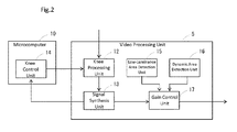
- Figure 2 is a functional block diagram of the video processing unit 5 and the microcomputer 10. As illustrated in Figure 2 , the video processing unit 5 comprises a knee processing unit 12 for performing knee processing on a long exposure signal; and a signal synthesis unit 13 for synthesizing the knee-processed long exposure signal and short exposure signal.
- knee processing is performed in which a long exposure signal having a luminance level equal to or higher than a knee point (a reference luminance level at which knee processing is performed) is compressed at a predetermined compression rate, to decrease the inclination of an incident light amount-luminance level line (a line representing the variation of a luminance level with the amount of incident light input to the imaging unit 3).
- the knee point and the compression rate used in knee processing are adjusted by the knee control unit 14 of the microcomputer 10.
- knee control is performed so as to make the knee point lower with an increase in the luminance level of a synthesized signal of the long exposure signal and the short exposure signal synthesized by the signal synthesis unit 13 and revert (increase) the inclination of an incident light amount-luminance level line to the original state thereof. Note that details on this knee control (adjustment of the knee point and the compression rate) will be described later using drawings.
- the video processing unit 5 also comprises: a low-luminance area detection unit 15 having a function to detect a low-luminance area (low-luminance area at a predetermined threshold luminance level or lower) if a dark dart is contained within a screen; and a dynamic area detection unit 16 having a function to detect a moving part (dynamic area) if the dynamic area is contained within a screen.
- the video processing unit 5 further comprises a gain control unit 17 for raising the gain of long exposure signals in these low-luminance and dynamic areas. Note that details on this gain control will be described later using drawings.
- Figure 3 is a drawing illustrating one example of an image (monitoring image) taken by the camera device 1.
- the image contains a sunny part (bright part) on the left side of a screen. Accordingly, in this case, exposure control using a long exposure signal and a short exposure signal is performed. Specifically, the adjustment of a knee point and a compression rate is made according to the luminance level of a synthesized signal of the long exposure signal and the short exposure signal, and knee processing is performed on the long exposure signal.
- FIG 4 is an explanatory drawing of knee control (adjustment of a knee point and a compression rate).
- knee processing for compressing signals at the luminance level of a knee point or higher is performed on a long exposure signal when a bright subject is photographed.
- knee control is performed so as to make the knee point lower with an increase in the luminance level of a synthesized signal of a long exposure signal and a short exposure signal and revert (increase) the inclination of an incident light amount-luminance level line to the original state thereof.
- the image contains a shady part (shown by shading in the figure) in the lower-right corner of a screen. Accordingly, the low-luminance area detection unit 15 detects this shady part as a low-luminance area, and the gain control unit 17 performs gain control for raising the gain of long exposure signals in the shade part. Yet additionally, in the example of Figure 3 , four pedestrians are included in the screen. Accordingly, the dynamic area detection unit 16 detects these pedestrians' parts as dynamic areas, and the gain control unit 17 performs gain control for raising the gain of long exposure signals in these pedestrians' parts.
- FIG. 5 is an explanatory drawing of knee control (adjustment of a knee point and a compression rate) and gain control (gain control of, for example, low-luminance areas).
- knee processing for compressing signals at the luminance level of a knee point or higher is performed on a long exposure signal when a bright subject is photographed.
- knee control is performed so as to make the knee point lower with an increase in the luminance level of a synthesized signal of a long exposure signal and a short exposure signal and revert (increase) the inclination of an incident light amount-luminance level line to the original state thereof.
- gain control for raising the gain of long exposure signals in a low-luminance area is also performed.
- a camera device 1 of an embodiment of the present invention as described above, it is possible to obtain a sharply-contrasted image in a bright part within a screen by providing the knee control unit 14 for adjusting the knee point and the compression rate, so as to make the knee point lower with an increase in the luminance level of a synthesized signal of long exposure signals and short exposure signals and revert the inclination of an incident light amount-luminance level line to the original state thereof.
- the present embodiment it is possible to obtain an image having an expanded dynamic range when a bright subject is photographed (in a case, for example, where the luminance level of a bright part within a screen is extremely high or the area of the bright part is large) by synthesizing a long exposure signal and a short exposure signal.
- knee control to adjust a knee point and a compression rate according to the luminance level of a synthesized signal of the long exposure signal and the short exposure signal is performed in knee processing with respect to long exposure signals (specifically, the knee point and the compression rate are adjusted, so as to make the knee point lower with an increase in the luminance level of the synthesized signal and revert the inclination to the original state thereof).
- gain control to raise the gain of long exposure signals in the low-luminance area is performed when a dark part (low-luminance area) is detected within the screen. If knee control to adjust the knee point and the compression rate is performed on long exposure signals, an image of the low-luminance area (dark part within a screen) may become somewhat distorted.
- gain control to raise the gain of long exposure signals in the low-luminance area as described above, it is possible to obtain an image in which even the dark part within a screen is clearly visible. Accordingly, visibility with respect to dark parts required particularly of a monitoring camera and the like is improved.
- gain control to raise the gain of long exposure signals in the dynamic area is performed when a moving subject is detected within the screen. Consequently, it is possible to obtain an image in which the moving subject within a screen is clearly visible. Accordingly, visibility with respect to moving subjects required particularly of a monitoring camera and the like is improved.
- a camera device has the advantage of being able to obtain an image sharply contrasted in bright parts within a screen. Accordingly, the camera device is used as a monitoring camera or the like and is, therefore, useful.
Landscapes
- Engineering & Computer Science (AREA)
- Multimedia (AREA)
- Signal Processing (AREA)
- Studio Devices (AREA)
- Transforming Light Signals Into Electric Signals (AREA)
Abstract
Description
- The present invention relates to a camera device including a function to expand a dynamic range by using a long exposure signal and a short exposure signal.
- Conventionally, various backlight correction techniques have been used in camera devices. As one of the backlight correction techniques, there is known, for example, a method for expanding a dynamic range by using an image pickup element in which a long exposure signal (video signal having a long exposure time) and a short exposure signal (video signal having a short exposure time) are output within one field period (see, for example, Patent Literature 1). In general, in a conventional method, knee processing for compressing a signal at the luminance level of a knee point (predetermined luminance level) or higher is performed in order to widen a dynamic range. After the knee-processed long exposure signal and short exposure signal are synthesized, a tone correction is made to the synthesized signal to output a final video signal. Note that the synthesis of the long exposure signal and the short exposure signal is performed so that the long exposure signal is used for luminance levels lower than the predetermined luminance level (synthesis point), and the short exposure signal is used for the luminance level of the synthesis point or higher.
- In commonly-used knee processing, a knee point is a fixed value. In that case, there has been the problem that it is difficult to smoothly synthesize the long exposure signal and the short exposure signal, thus causing a sense of gradation to deteriorate. Hence, there has been conventionally proposed a technique to perform control, so as to lower the knee point of a long exposure signal and raise the gain of a short exposure signal, only when a subject (extremely bright subject) for which a dynamic range needs to be expanded is photographed.
-
Figure 6 is an explanatory drawing of knee point control in conventional knee processing. As illustrated inFigure 6(a) , knee processing for compressing signals at the luminance level of a knee point or higher is performed on a long exposure signal when a bright subject is photographed. On the other hand, as illustrated inFigure 6(b) , a knee point adjustment is made so as to lower the knee point when a brighter subject is photographed. Consequently, it is possible to obtain an image improved to some degree in the sense of gradation. - However, simply lowering the knee point of a long exposure signal as in the conventional method is not sufficient in terms of improvement in the sense of gradation. That is, since an inclination at the synthesis point of the long exposure signal and the short exposure signal (inclination of an incident light amount-luminance level line representing a variation of the luminance level with the incident light amount) differs, an image taken results in a weakly-contrasted image. In addition, in the conventional method, the long exposure signal and the short exposure signal differ in inclination at such a comparatively high-brightness part (bright part within an image) as the synthesis point of the long exposure signal and the short exposure signal. This gives the impression that gradational variation is not smooth (even in the case of such a degree of shift in gradational variation as not to be concerned about in dark parts within a screen).
-
- Patent Literature 1: Japanese Patent Laid-Open No.
2001-197362 - The present invention has been accomplished under the above-described circumstances. Accordingly, an object of the present invention is to provide a camera device capable of expanding a dynamic range by using a long exposure signal and a short exposure signal, and obtaining an image sharply contrasted in bright parts within a screen.
- One aspect of the present invention is a camera device, and this camera device comprises: an imaging unit for outputting a long exposure signal which is a video signal having a long exposure time and a short exposure signal which is a video signal having a short exposure time within one field period; a knee processing unit for compressing, at a predetermined compression rate, the long exposure signal having a luminance level equal to or higher than a knee point which is a reference luminance level at which knee processing is performed, to decrease the inclination of an incident light amount-luminance level line representing the variation of a luminance level with the amount of incident light input to the imaging unit; and a knee control unit for adjusting the knee point and the compression rate according to the luminance level of a synthesized signal obtained by synthesizing the long exposure signal and the short exposure signal, so as to make the knee point lower with an increase in the luminance level and revert the inclination to the original state thereof.
- Another aspect of the present invention is an exposure control method, and this exposure control method is used in a camera device comprising an imaging unit for outputting a long exposure signal which is a video signal having a long exposure time and a short exposure signal which is a video signal having a short exposure time within one field period, the method including: compressing, at a predetermined compression rate, the long exposure signal having a luminance level equal to or higher than a knee point which is a reference luminance level at which knee processing is performed, to decrease the inclination of an incident light amount-luminance level line representing the variation of a luminance level with the amount of incident light input to the imaging unit; and adjusting the knee point and the compression rate according to the luminance level of a synthesized signal obtained by synthesizing the long exposure signal and the short exposure signal, so as to make the knee point lower with an increase in the luminance level and revert the inclination to the original state thereof.
- Yet another aspect of the present invention is a program, and this program is used for the exposure control of a camera device comprising an imaging unit for outputting a long exposure signal which is a video signal having a long exposure time and a short exposure signal which is a video signal having a short exposure time within one field period; the program causing a computer to perform the processes of:
- compressing, at a predetermined compression rate, the long exposure signal having a luminance level equal to or higher than a knee point which is a reference luminance level at which knee processing is performed, to decrease the inclination of an incident light amount-luminance level line representing the variation of a luminance level with the amount of incident light input to the imaging unit; and
- adjusting the knee point and the compression rate according to the luminance level of a synthesized signal obtained by synthesizing the long exposure signal and the short exposure signal, so as to make the knee point lower with an increase in the luminance level and revert the inclination to the original state thereof.
- As will be described hereinafter, the present invention includes other aspects. Accordingly, this disclosure of the present invention is intended to provide some aspects of the present invention, and is not intended to restrict the scope of the invention described and claimed herein.
-
- [
Figure 1] Figure 1 is a block diagram illustrating an overall configuration of a camera device in an embodiment of the present invention. - [
Figure 2] Figure 2 is a functional block diagram of a video processing unit and a microcomputer of a camera device. - [
Figure 3] Figure 3 is a drawing illustrating one example of an image (monitoring image) taken with a camera device. - [
Figure 4] Figure 4(a) is an explanatory drawing of a knee point, whereasFigure 4(b) is an explanatory drawing of knee control (adjustment of a knee point and a compression rate) in the present invention. - [
Figure 5] Figure 5(a) is an explanatory drawing of a knee point, whereasFigure 5(b) is an explanatory drawing of knee control (adjustment of a knee point and a compression rate) and gain control in the present invention. - [
Figure 6] Figure 6(a) is an explanatory drawing of a knee point, whereasFigure 6(b) is an explanatory drawing of conventional knee control (adjustment of a knee point). - Hereinafter, the present invention will be described in detail. It should be noted, however, that the detailed description given hereinafter and the accompanying drawings do not restrict the invention.
- A camera device of the present invention has a configuration comprising: an imaging unit for outputting a long exposure signal which is a video signal having a long exposure time and a short exposure signal which is a video signal having a short exposure time within one field period; a knee processing unit for compressing, at a predetermined compression rate, the long exposure signal having a luminance level equal to or higher than a knee point which is a reference luminance level at which knee processing is performed, to decrease the inclination of an incident light amount-luminance level line representing the variation of a luminance level with the amount of incident light input to the imaging unit; and a knee control unit for adjusting the knee point and the compression rate according to the luminance level of a synthesized signal obtained by synthesizing the long exposure signal and the short exposure signal, so as to make the knee point lower with an increase in the luminance level and revert the inclination to the original state thereof.
- According to this configuration, it is possible to obtain an image having an expanded dynamic range when a bright subject is photographed (in a case, for example, where the luminance level of a bright part within a screen is extremely high or the area of the bright part is large) by synthesizing a long exposure signal and a short exposure signal. In addition, in this case, knee control to adjust a knee point and a compression rate according to the luminance level of the synthesized signal of the long exposure signal and the short exposure signal is performed in knee processing with respect to the long exposure signal (specifically, the knee point and the compression rate are adjusted, so as to make the knee point lower with an increase in the luminance level and revert the inclination to the original state thereof). Consequently, the inclinations of the incident light amount-luminance level lines of the long exposure signal and the short exposure signal approximate to each other in the vicinity of a synthesis point of the long exposure signal and the short exposure signal. Accordingly, it is possible to obtain an image sharply contrasted (an image smooth in gradational variation, i.e., a linearly-gradated image) in bright parts within a screen (near the synthesis point).
- In addition, the camera device of the present invention may have a configuration comprising: a low-luminance area detection unit for detecting a low-luminance area at a predetermined threshold luminance level or lower in an image obtained by synthesizing the long exposure signal and the short exposure signal; and a gain control unit for raising the gain of the long exposure signal in the low-luminance area.
- According to this configuration, gain control to raise the gain of long exposure signals in the low-luminance area is performed when a dark part (low-luminance area) is detected within a screen. If knee control to adjust the knee point and the compression rate is performed on long exposure signals, an image of the low-luminance area (dark part within a screen) may become somewhat distorted. By performing gain control to raise the gain of long exposure signals in the low-luminance area as described above, it is possible to obtain an image in which even the dark part within a screen is clearly visible. Accordingly, visibility with respect to dark parts required particularly of a monitoring camera and the like is improved.
- The camera device of the present invention may have a configuration comprising: a dynamic area detection unit for detecting a dynamic area including a moving subject in an image obtained by synthesizing the long exposure signal and the short exposure signal; and a second gain control unit for raising the gain of the long exposure signal in the dynamic area.
- According to this configuration, gain control to raise the gain of long exposure signals in the dynamic area is performed when a moving subject is detected within a screen. Consequently, it is possible to obtain an image in which the moving subject within a screen is clearly visible. Accordingly, visibility with respect to moving subjects required particularly of a monitoring camera and the like is improved.
- An exposure control method of the present invention used in a camera device comprising an imaging unit for outputting a long exposure signal which is a video signal having a long exposure time and a short exposure signal which is a video signal having a short exposure time within one field period, includes: compressing, at a predetermined compression rate, the long exposure signal having a luminance level equal to or higher than a knee point which is a reference luminance level at which knee processing is performed, to decrease the inclination of an incident light amount-luminance level line representing the variation of a luminance level with the amount of incident light input to the imaging unit; and adjusting the knee point and the compression rate according to the luminance level of a synthesized signal obtained by synthesizing the long exposure signal and the short exposure signal, so as to make the knee point lower with an increase in the luminance level and revert the inclination to the original state thereof.
- Also according to this method, it is possible to obtain an image having an expanded dynamic range when a bright subject is photographed (in a case, for example, where the luminance level of a bright part within a screen is extremely high or the area of the bright part is large) by synthesizing a long exposure signal and a short exposure signal, as described above. In addition, knee control to adjust the knee point and the compression rate according to the luminance level of the synthesized signal of the long exposure signal and the short exposure signal is performed in knee processing with respect to long exposure signals (specifically, the knee point and the compression rate are adjusted, so as to make the knee point lower with an increase in the luminance level and revert the inclination to the original state thereof). Consequently, the inclinations of incident light amount-luminance level lines of long exposure signals and short exposure signals approximate to each other in the vicinity of a synthesis point of the long exposure signal and the short exposure signal. Accordingly, it is possible to obtain an image sharply contrasted (an image smooth in gradational variation, i.e., a linearly-gradated image) in bright parts within a screen (near the synthesis point).
- A program of the present invention used for the exposure control of a camera device comprising an imaging unit for outputting a long exposure signal which is a video signal having a long exposure time and a short exposure signal which is a video signal having a short exposure time within one field period, causes a computer to perform the processes of: compressing, at a predetermined compression rate, the long exposure signal having a luminance level equal to or higher than a knee point which is a reference luminance level at which knee processing is performed, to decrease the inclination of an incident light amount-luminance level line representing the variation of a luminance level with the amount of incident light input to the imaging unit; and adjusting the knee point and the compression rate according to the luminance level of a synthesized signal obtained by synthesizing the long exposure signal and the short exposure signal, so as to make the knee point lower with an increase in the luminance level and revert the inclination to the original state thereof.
- Also according to this program, it is possible to obtain an image having an expanded dynamic range when a bright subject is photographed (in a case, for example, where the luminance level of a bright part within a screen is extremely high or the area of the bright part is large) by synthesizing the long exposure signal and the short exposure signal, as described above. In addition, knee control to adjust the knee point and the compression rate according to the luminance level of the synthesized signal of the long exposure signal and the short exposure signal is performed in knee processing with respect to long exposure signals (specifically, the knee point and the compression rate are adjusted, so as to make the knee point lower with an increase in the luminance level and revert the inclination to the original state thereof). Consequently, the inclinations of the incident light amount-luminance level lines of the long exposure signal and the short exposure signal approximate to each other in the vicinity of a synthesis point of the long exposure signal and the short exposure signal. Accordingly, it is possible to obtain an image sharply contrasted (an image smooth in gradational variation, i.e., a linearly-gradated image) in bright parts within a screen (near the synthesis point).
- The present invention makes it possible to obtain an image sharply contrasted in bright parts within a screen by adjusting the knee point and the compression rate, so as to make the knee point lower with an increase in the luminance level and revert the inclination of an incident light amount-luminance level line to the original state thereof.
- Hereinafter, a camera device according to an embodiment of the present invention will be described using drawings. In the present embodiment, a camera device used in a monitoring camera or the like will be cited by way of example. This camera device includes an exposure control function. This function is realized by a program stored in a memory or the like of the camera device.
- A configuration of the camera device according to an embodiment of the present invention will be described with reference to drawings.
Figure 1 is a block diagram illustrating an overall configuration of the camera device of the present embodiment. As illustrated inFigure 1 , acamera device 1 comprises alens unit 2 including an optical lens and an aperture diaphragm, and an imaging unit 3 including an image pickup element, such as a CCD. The image pickup element of this imaging unit 3 has a double-speed driving function to output a long exposure signal (video signal having a long exposure time) and a short exposure signal (video signal having a short exposure time) within one field period. - In addition, the
camera device 1 comprises: an analogsignal processing unit 4 for performing predetermined preprocessing on a long exposure signal and a short exposure signal output from the imaging unit 3; avideo processing unit 5 for performing predetermined video processing on a long exposure signal and a short exposure signal output from the analogsignal processing unit 4; and a videosignal generation unit 6 for synthesizing a long exposure signal and a short exposure signal output from thevideo processing unit 5 to output a final video signal. Note that processing to make a tone correction to a synthesized signal of the long exposure signal and the short exposure signal is performed at this videosignal generation unit 6. - The analog
signal processing unit 4 comprises: aCDS unit 7 for performing correlated double sampling processing (CDS processing) on a long exposure signal and a short exposure signal output from the imaging unit 3; anAGC unit 8 for performing automatic gain control (AGC) on the CDS-processed long exposure signal and short exposure signal; and an A/D unit 9 for performing analog/digital conversion processing (A/D conversion processing) on the automatic gain-controlled long exposure signal and short exposure signal. Thiscamera device 1 includes amicrocomputer 10 for controlling the operation of respective units, and the operation of the analogsignal processing unit 4 and thevideo processing unit 5 is controlled by themicrocomputer 10. - This
camera device 1 further comprises an aperturediaphragm adjustment unit 11 for adjusting the aperture diaphragm of thelens unit 2. This aperturediaphragm adjustment unit 11 is controlled by themicrocomputer 10, so as to adjust the amount of aperture according to the luminance level of a synthesized signal of a long exposure signal and a short exposure signal. Accordingly, at the time of normal photography (when any bright subjects are not photographed), it is possible to obtain an image having appropriate brightness (luminance level) by adjusting the amount of aperture by using the aperturediaphragm adjustment unit 11. - Next, the functions of the
video processing unit 5 will be described with reference toFigure 2 . Thevideo processing unit 5 comprises, for example, a DSP and has various functions related to the exposure control of the present invention.Figure 2 is a functional block diagram of thevideo processing unit 5 and themicrocomputer 10. As illustrated inFigure 2 , thevideo processing unit 5 comprises aknee processing unit 12 for performing knee processing on a long exposure signal; and asignal synthesis unit 13 for synthesizing the knee-processed long exposure signal and short exposure signal. - In the
knee processing unit 12, knee processing is performed in which a long exposure signal having a luminance level equal to or higher than a knee point (a reference luminance level at which knee processing is performed) is compressed at a predetermined compression rate, to decrease the inclination of an incident light amount-luminance level line (a line representing the variation of a luminance level with the amount of incident light input to the imaging unit 3). The knee point and the compression rate used in knee processing are adjusted by theknee control unit 14 of themicrocomputer 10. Specifically, knee control is performed so as to make the knee point lower with an increase in the luminance level of a synthesized signal of the long exposure signal and the short exposure signal synthesized by thesignal synthesis unit 13 and revert (increase) the inclination of an incident light amount-luminance level line to the original state thereof. Note that details on this knee control (adjustment of the knee point and the compression rate) will be described later using drawings. - The
video processing unit 5 also comprises: a low-luminancearea detection unit 15 having a function to detect a low-luminance area (low-luminance area at a predetermined threshold luminance level or lower) if a dark dart is contained within a screen; and a dynamicarea detection unit 16 having a function to detect a moving part (dynamic area) if the dynamic area is contained within a screen. Thevideo processing unit 5 further comprises again control unit 17 for raising the gain of long exposure signals in these low-luminance and dynamic areas. Note that details on this gain control will be described later using drawings. - The operation of the
camera device 1 configured as described above will be described with reference to drawings. Here, the operation will be described with a focus on the characteristic behaviors (exposure control using a long exposure signal and a short exposure signal) of the present invention. - Note that it is possible to obtain an image having appropriate brightness (luminance level) at the time of normal photography (when any bright subjects are not photographed) by adjusting the amount of aperture by using the aperture
diaphragm adjustment unit 11, though this will not be explained here. In addition, if somewhat bright parts (parts too bright to be coped with by aperture diaphragm adjustment alone) are contained within a screen, knee processing is performed on the bright parts by theknee processing unit 12 to expand a dynamic range, though exposure control of the present invention by using a long exposure signal and a short exposure signal is not performed. That is, exposure control using the long exposure signal and the short exposure signal to be described hereinafter is performed when any extremely bright parts (parts too bright to be coped with by knee processing alone) are contained within a screen. -
Figure 3 is a drawing illustrating one example of an image (monitoring image) taken by thecamera device 1. In the example ofFigure 3 , the image contains a sunny part (bright part) on the left side of a screen. Accordingly, in this case, exposure control using a long exposure signal and a short exposure signal is performed. Specifically, the adjustment of a knee point and a compression rate is made according to the luminance level of a synthesized signal of the long exposure signal and the short exposure signal, and knee processing is performed on the long exposure signal. -
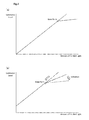
Figure 4 is an explanatory drawing of knee control (adjustment of a knee point and a compression rate). As illustrated inFigure 4(a) , knee processing for compressing signals at the luminance level of a knee point or higher is performed on a long exposure signal when a bright subject is photographed. In this case, as illustrated inFigure 4(b) , knee control is performed so as to make the knee point lower with an increase in the luminance level of a synthesized signal of a long exposure signal and a short exposure signal and revert (increase) the inclination of an incident light amount-luminance level line to the original state thereof. - In addition, in the example of
Figure 3 , the image contains a shady part (shown by shading in the figure) in the lower-right corner of a screen. Accordingly, the low-luminancearea detection unit 15 detects this shady part as a low-luminance area, and thegain control unit 17 performs gain control for raising the gain of long exposure signals in the shade part. Yet additionally, in the example ofFigure 3 , four pedestrians are included in the screen. Accordingly, the dynamicarea detection unit 16 detects these pedestrians' parts as dynamic areas, and thegain control unit 17 performs gain control for raising the gain of long exposure signals in these pedestrians' parts. -
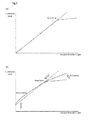
Figure 5 is an explanatory drawing of knee control (adjustment of a knee point and a compression rate) and gain control (gain control of, for example, low-luminance areas). As illustrated inFigure 5(a) , knee processing for compressing signals at the luminance level of a knee point or higher is performed on a long exposure signal when a bright subject is photographed. In this case, as illustrated inFigure 5(b) , knee control is performed so as to make the knee point lower with an increase in the luminance level of a synthesized signal of a long exposure signal and a short exposure signal and revert (increase) the inclination of an incident light amount-luminance level line to the original state thereof. In addition, gain control for raising the gain of long exposure signals in a low-luminance area is also performed. - According to such a
camera device 1 of an embodiment of the present invention as described above, it is possible to obtain a sharply-contrasted image in a bright part within a screen by providing theknee control unit 14 for adjusting the knee point and the compression rate, so as to make the knee point lower with an increase in the luminance level of a synthesized signal of long exposure signals and short exposure signals and revert the inclination of an incident light amount-luminance level line to the original state thereof. - That is, in the present embodiment, it is possible to obtain an image having an expanded dynamic range when a bright subject is photographed (in a case, for example, where the luminance level of a bright part within a screen is extremely high or the area of the bright part is large) by synthesizing a long exposure signal and a short exposure signal. In addition, in this case, knee control to adjust a knee point and a compression rate according to the luminance level of a synthesized signal of the long exposure signal and the short exposure signal is performed in knee processing with respect to long exposure signals (specifically, the knee point and the compression rate are adjusted, so as to make the knee point lower with an increase in the luminance level of the synthesized signal and revert the inclination to the original state thereof). Consequently, the inclinations of incident light amount-luminance level lines of the long exposure signal and the short exposure signal approximate to each other in the vicinity of a synthesis point of the long exposure signal and the short exposure signal. Accordingly, it is possible to obtain an image sharply contrasted (an image smooth in gradational variation, i.e., a linearly-gradated image) in bright parts within a screen (near the synthesis point).
- In addition, in the present embodiment, gain control to raise the gain of long exposure signals in the low-luminance area is performed when a dark part (low-luminance area) is detected within the screen. If knee control to adjust the knee point and the compression rate is performed on long exposure signals, an image of the low-luminance area (dark part within a screen) may become somewhat distorted. By performing gain control to raise the gain of long exposure signals in the low-luminance area as described above, it is possible to obtain an image in which even the dark part within a screen is clearly visible. Accordingly, visibility with respect to dark parts required particularly of a monitoring camera and the like is improved.
- Yet additionally, gain control to raise the gain of long exposure signals in the dynamic area is performed when a moving subject is detected within the screen. Consequently, it is possible to obtain an image in which the moving subject within a screen is clearly visible. Accordingly, visibility with respect to moving subjects required particularly of a monitoring camera and the like is improved.
- While embodiments of the present invention have been described heretofore by way of example, the scope of the present invention is not limited to those embodiments. The invention may be altered or modified according to the purpose thereof within the scope of the appended claims.
- While there has been described what are considered at present preferred embodiments of the present invention, it is to be understood that various modifications may be made thereto, and it is intended that the appended claims cover all such modifications that fall within the true spirit and scope of the invention.
- As has been described heretofore, a camera device according to the present invention has the advantage of being able to obtain an image sharply contrasted in bright parts within a screen. Accordingly, the camera device is used as a monitoring camera or the like and is, therefore, useful.
-
- 1
- Camera device
- 3
- Imaging unit
- 4
- Analog signal processing unit
- 5
- Video processing unit
- 6
- Video signal generation unit
- 10
- Microcomputer
- 12
- Knee processing unit
- 13
- Signal synthesis unit
- 14
- Knee control unit
- 15
- Low-luminance area detection unit
- 16
- Dynamic area detection unit
- 17
- Gain control unit
Claims (5)
- A camera device comprising:an imaging unit which outputs a long exposure signal and a short exposure signal, the long exposure signal being a video signal which has a long exposure time and the short exposure signal being a video signal which has a short exposure time within one field period;a knee processing unit which compresses, at a predetermined compression rate, the long exposure signal which has a luminance level equal to or higher than a knee point which is a reference luminance level at which knee processing is performed, to decrease the inclination of an incident light amount-luminance level line which represents the variation of a luminance level with the amount of incident light input to the imaging unit; anda knee control unit which adjusts the knee point and the compression rate according to the luminance level of a synthesized signal obtained by synthesizing the long exposure signal and the short exposure signal, so as to make the knee point lower with an increase in the luminance level and revert the inclination to the original state thereof.
- The camera device according to claim 1, further comprising:a low-luminance area detection unit which detects a low-luminance area at a predetermined threshold luminance level or lower in an image obtained by synthesizing the long exposure signal and the short exposure signal; anda gain control unit which raises the gain of the long exposure signal in the low-luminance area.
- The camera device according to claim 1, further comprising:a dynamic area detection unit which detects a dynamic area which includes a moving subject in an image obtained by synthesizing the long exposure signal and the short exposure signal; anda second gain control unit which raises the gain of the long exposure signal in the dynamic area.
- An exposure control method used in a camera device comprising an imaging unit which outputs a long exposure signal and a short exposure signal, the long exposure signal being a video signal which has a long exposure time and a short exposure signal being a video signal which has a short exposure time within one field period, the method including:compressing, at a predetermined compression rate, the long exposure signal which has a luminance level equal to or higher than a knee point which is a reference luminance level at which knee processing is performed, to decrease the inclination of an incident light amount-luminance level line which represents the variation of a luminance level with the amount of incident light input to the imaging unit; andadjusting the knee point and the compression rate according to the luminance level of a synthesized signal obtained by synthesizing the long exposure signal and the short exposure signal, so as to make the knee point lower with an increase in the luminance level and revert the inclination to the original state thereof.
- A program used for the exposure control of a camera device comprising an imaging unit which outputs a long exposure signal and a short exposure signal, the long exposure signal being a video signal which has a long exposure time and a short exposure signal being a video signal which has a short exposure time within one field period; the program causing a computer to perform the processes of:compressing, at a predetermined compression rate, the long exposure signal which has a luminance level equal to or higher than a knee point which is a reference luminance level at which knee processing is performed, to decrease the inclination of an incident light amount-luminance level line which represents the variation of a luminance level with the amount of incident light input to the imaging unit; andadjusting the knee point and the compression rate according to the luminance level of a synthesized signal obtained by synthesizing the long exposure signal and the short exposure signal, so as to make the knee point lower with an increase in the luminance level and revert the inclination to the original state thereof.
Applications Claiming Priority (2)
| Application Number | Priority Date | Filing Date | Title |
|---|---|---|---|
| JP2009124961A JP5005731B2 (en) | 2009-05-25 | 2009-05-25 | Camera apparatus and exposure control method |
| PCT/JP2010/002361 WO2010137224A1 (en) | 2009-05-25 | 2010-03-31 | Camera device, exposure control method, and program |
Publications (2)
| Publication Number | Publication Date |
|---|---|
| EP2429181A1 true EP2429181A1 (en) | 2012-03-14 |
| EP2429181A4 EP2429181A4 (en) | 2012-03-28 |
Family
ID=43222356
Family Applications (1)
| Application Number | Title | Priority Date | Filing Date |
|---|---|---|---|
| EP10780186A Ceased EP2429181A4 (en) | 2009-05-25 | 2010-03-31 | CAMERA DEVICE, EXPOSURE SETTING METHOD, AND PROGRAM |
Country Status (5)
| Country | Link |
|---|---|
| US (1) | US8477212B2 (en) |
| EP (1) | EP2429181A4 (en) |
| JP (1) | JP5005731B2 (en) |
| CN (1) | CN102449997B (en) |
| WO (1) | WO2010137224A1 (en) |
Families Citing this family (10)
| Publication number | Priority date | Publication date | Assignee | Title |
|---|---|---|---|---|
| JP5821571B2 (en) * | 2011-11-28 | 2015-11-24 | 富士通株式会社 | Image composition apparatus and image composition method |
| US9456146B2 (en) | 2011-12-22 | 2016-09-27 | Panasonic Intellectual Property Management Co., Ltd. | Exposure control device, imaging device, image display device, and exposure control method |
| US9172869B2 (en) * | 2013-12-04 | 2015-10-27 | Omnivision Technologies, Inc. | Image data aggregating high dynamic range imaging systems and associated methods |
| WO2016059877A1 (en) * | 2014-10-17 | 2016-04-21 | ソニー株式会社 | Controller, control method, and flight vehicle device |
| US10880504B2 (en) | 2016-12-27 | 2020-12-29 | Canon Kabushiki Kaisha | Image pickup device, image capturing system, and movable body |
| CN107592472B (en) * | 2017-10-20 | 2019-12-20 | 思特威(上海)电子科技有限公司 | Imaging correction method of multi-exposure image sensor |
| US11637963B2 (en) | 2019-07-16 | 2023-04-25 | Samsung Electronics Co., Ltd. | Image sensor and image processing system comprising the same |
| CN112243090B (en) | 2019-07-16 | 2024-10-18 | 三星电子株式会社 | Image sensor and image processing system |
| JP7831812B2 (en) | 2020-01-28 | 2026-03-17 | i-PRO株式会社 | Surveillance camera, camera parameter determination method, and program |
| US12407939B2 (en) | 2022-09-15 | 2025-09-02 | Samsung Electronics Co., Ltd. | Method of operating image sensor and image device performing the same |
Family Cites Families (17)
| Publication number | Priority date | Publication date | Assignee | Title |
|---|---|---|---|---|
| JP2979567B2 (en) * | 1990-02-15 | 1999-11-15 | ソニー株式会社 | Exposure compensation device for video camera |
| JPH05103256A (en) * | 1991-10-11 | 1993-04-23 | Canon Inc | Image pickup device |
| US6141047A (en) * | 1993-12-22 | 2000-10-31 | Canon Kabushiki Kaisha | Image signal processing apparatus and image pickup device |
| KR100371428B1 (en) * | 1995-03-28 | 2003-04-08 | 마츠시타 덴끼 산교 가부시키가이샤 | Image recording apparatus and image reproducing apparatus |
| US6219097B1 (en) * | 1996-05-08 | 2001-04-17 | Olympus Optical Co., Ltd. | Image pickup with expanded dynamic range where the first exposure is adjustable and second exposure is predetermined |
| EP0910209B1 (en) * | 1997-10-17 | 2010-04-14 | Panasonic Corporation | A video camera having an increased dynamic range |
| JP4207259B2 (en) * | 1998-09-01 | 2009-01-14 | ソニー株式会社 | Video signal processing device |
| JP3642245B2 (en) * | 2000-01-14 | 2005-04-27 | 松下電器産業株式会社 | Solid-state imaging device |
| JP3645502B2 (en) | 2001-06-29 | 2005-05-11 | 株式会社東芝 | Imaging apparatus and video signal processing method |
| JP3801126B2 (en) * | 2002-09-25 | 2006-07-26 | ソニー株式会社 | Imaging apparatus, image output method of imaging apparatus, and computer program |
| JP4289244B2 (en) | 2004-07-16 | 2009-07-01 | ソニー株式会社 | Image processing method, semiconductor device for detecting physical quantity distribution, and electronic apparatus |
| JP4452161B2 (en) | 2004-11-12 | 2010-04-21 | パナソニック株式会社 | Imaging device |
| JP4649313B2 (en) * | 2005-10-28 | 2011-03-09 | 株式会社東芝 | Solid-state imaging device |
| JP4131280B2 (en) * | 2006-04-20 | 2008-08-13 | ソニー株式会社 | Imaging apparatus and video signal processing method |
| US8144214B2 (en) * | 2007-04-18 | 2012-03-27 | Panasonic Corporation | Imaging apparatus, imaging method, integrated circuit, and storage medium |
| JP2009152669A (en) * | 2007-12-18 | 2009-07-09 | Sony Corp | Imaging apparatus, imaging processing method, and imaging control program |
| KR101495895B1 (en) * | 2008-07-08 | 2015-02-25 | 삼성전자주식회사 | Photo-electricity converter having wide dynamic range and method thereof |
-
2009
- 2009-05-25 JP JP2009124961A patent/JP5005731B2/en not_active Expired - Fee Related
-
2010
- 2010-03-31 EP EP10780186A patent/EP2429181A4/en not_active Ceased
- 2010-03-31 WO PCT/JP2010/002361 patent/WO2010137224A1/en not_active Ceased
- 2010-03-31 US US13/321,747 patent/US8477212B2/en not_active Expired - Fee Related
- 2010-03-31 CN CN201080022775.9A patent/CN102449997B/en not_active Expired - Fee Related
Also Published As
| Publication number | Publication date |
|---|---|
| JP2010273239A (en) | 2010-12-02 |
| CN102449997B (en) | 2015-01-14 |
| JP5005731B2 (en) | 2012-08-22 |
| US20120120280A1 (en) | 2012-05-17 |
| WO2010137224A1 (en) | 2010-12-02 |
| CN102449997A (en) | 2012-05-09 |
| EP2429181A4 (en) | 2012-03-28 |
| US8477212B2 (en) | 2013-07-02 |
Similar Documents
| Publication | Publication Date | Title |
|---|---|---|
| US8477212B2 (en) | Camera device, exposure control method, and program | |
| US7825955B2 (en) | Image pickup apparatus, exposure control method, and computer program installed in the image pickup apparatus | |
| CN101800857B (en) | Image capturing apparatus and control method thereof | |
| US8483507B2 (en) | Image sensing apparatus and image processing method | |
| CN101800858B (en) | Image capturing apparatus and control method thereof | |
| JP5624809B2 (en) | Image signal processing device | |
| US7961228B2 (en) | Imaging apparatus and method for controlling exposure by determining backlight situations and detecting a face | |
| US9338358B2 (en) | Image capture apparatus and control method for reflecting exposure compensation | |
| JP6873679B2 (en) | Imaging device, control method and program of imaging device | |
| JP4999871B2 (en) | Imaging apparatus and control method thereof | |
| JP2008206111A (en) | Photographing apparatus and photographing method | |
| US20090284616A1 (en) | Image signal processing circuit | |
| JP4600684B2 (en) | Imaging apparatus and imaging method | |
| US7486884B2 (en) | Imaging device and imaging method | |
| WO2020202885A1 (en) | Image capture device and image adjusting method | |
| JP2012124652A (en) | Imaging apparatus and image processing method | |
| JP2007082180A (en) | Imaging apparatus and image processing method | |
| JP5038190B2 (en) | Image capturing apparatus and setting method thereof | |
| JP5335964B2 (en) | Imaging apparatus and control method thereof | |
| US7876366B2 (en) | Electronic camera | |
| JP6090565B2 (en) | Imaging apparatus, imaging method, and program | |
| JP2008108024A (en) | Image processing apparatus and imaging apparatus | |
| JP2006013863A (en) | Contrast enhancement imaging device | |
| JP2005303595A (en) | Imaging apparatus | |
| KR20080000237A (en) | Back light compensation method of camera |
Legal Events
| Date | Code | Title | Description |
|---|---|---|---|
| PUAI | Public reference made under article 153(3) epc to a published international application that has entered the european phase |
Free format text: ORIGINAL CODE: 0009012 |
|
| 17P | Request for examination filed |
Effective date: 20111209 |
|
| AK | Designated contracting states |
Kind code of ref document: A1 Designated state(s): AT BE BG CH CY CZ DE DK EE ES FI FR GB GR HR HU IE IS IT LI LT LU LV MC MK MT NL NO PL PT RO SE SI SK SM TR |
|
| A4 | Supplementary search report drawn up and despatched |
Effective date: 20120228 |
|
| RIC1 | Information provided on ipc code assigned before grant |
Ipc: H04N 5/243 20060101AFI20120222BHEP Ipc: H04N 5/235 20060101ALI20120222BHEP Ipc: H04N 5/335 20110101ALI20120222BHEP |
|
| DAX | Request for extension of the european patent (deleted) | ||
| 17Q | First examination report despatched |
Effective date: 20121024 |
|
| REG | Reference to a national code |
Ref country code: DE Ref legal event code: R003 |
|
| STAA | Information on the status of an ep patent application or granted ep patent |
Free format text: STATUS: THE APPLICATION HAS BEEN REFUSED |
|
| 18R | Application refused |
Effective date: 20131031 |