EP2429016A1 - Battery cell - Google Patents
Battery cell Download PDFInfo
- Publication number
- EP2429016A1 EP2429016A1 EP11179109A EP11179109A EP2429016A1 EP 2429016 A1 EP2429016 A1 EP 2429016A1 EP 11179109 A EP11179109 A EP 11179109A EP 11179109 A EP11179109 A EP 11179109A EP 2429016 A1 EP2429016 A1 EP 2429016A1
- Authority
- EP
- European Patent Office
- Prior art keywords
- case
- battery cell
- terminal
- secondary battery
- terminal region
- Prior art date
- Legal status (The legal status is an assumption and is not a legal conclusion. Google has not performed a legal analysis and makes no representation as to the accuracy of the status listed.)
- Granted
Links
- 230000015572 biosynthetic process Effects 0.000 claims abstract description 30
- 238000005755 formation reaction Methods 0.000 claims abstract description 30
- 230000001419 dependent effect Effects 0.000 claims 1
- 238000009413 insulation Methods 0.000 description 26
- 239000003792 electrolyte Substances 0.000 description 17
- 230000000712 assembly Effects 0.000 description 16
- 238000000429 assembly Methods 0.000 description 16
- 230000000295 complement effect Effects 0.000 description 8
- -1 e.g. Substances 0.000 description 8
- 239000000463 material Substances 0.000 description 8
- 238000004519 manufacturing process Methods 0.000 description 7
- PXHVJJICTQNCMI-UHFFFAOYSA-N Nickel Chemical compound [Ni] PXHVJJICTQNCMI-UHFFFAOYSA-N 0.000 description 6
- 229920002943 EPDM rubber Polymers 0.000 description 4
- 229920000459 Nitrile rubber Polymers 0.000 description 4
- 229910052782 aluminium Inorganic materials 0.000 description 4
- XAGFODPZIPBFFR-UHFFFAOYSA-N aluminium Chemical compound [Al] XAGFODPZIPBFFR-UHFFFAOYSA-N 0.000 description 4
- 229920005549 butyl rubber Polymers 0.000 description 4
- 239000007772 electrode material Substances 0.000 description 4
- 239000012212 insulator Substances 0.000 description 4
- 229920003048 styrene butadiene rubber Polymers 0.000 description 4
- 238000003466 welding Methods 0.000 description 4
- 229910000838 Al alloy Inorganic materials 0.000 description 3
- 229910052759 nickel Inorganic materials 0.000 description 3
- OKTJSMMVPCPJKN-UHFFFAOYSA-N Carbon Chemical compound [C] OKTJSMMVPCPJKN-UHFFFAOYSA-N 0.000 description 2
- RYGMFSIKBFXOCR-UHFFFAOYSA-N Copper Chemical compound [Cu] RYGMFSIKBFXOCR-UHFFFAOYSA-N 0.000 description 2
- OIFBSDVPJOWBCH-UHFFFAOYSA-N Diethyl carbonate Chemical compound CCOC(=O)OCC OIFBSDVPJOWBCH-UHFFFAOYSA-N 0.000 description 2
- KMTRUDSVKNLOMY-UHFFFAOYSA-N Ethylene carbonate Chemical compound O=C1OCCO1 KMTRUDSVKNLOMY-UHFFFAOYSA-N 0.000 description 2
- 239000005062 Polybutadiene Substances 0.000 description 2
- 239000004698 Polyethylene Substances 0.000 description 2
- 239000004743 Polypropylene Substances 0.000 description 2
- 229910000831 Steel Inorganic materials 0.000 description 2
- 239000002174 Styrene-butadiene Substances 0.000 description 2
- 239000000853 adhesive Substances 0.000 description 2
- 230000001070 adhesive effect Effects 0.000 description 2
- 239000011248 coating agent Substances 0.000 description 2
- 238000000576 coating method Methods 0.000 description 2
- 229910052802 copper Inorganic materials 0.000 description 2
- 239000010949 copper Substances 0.000 description 2
- 238000010586 diagram Methods 0.000 description 2
- IEJIGPNLZYLLBP-UHFFFAOYSA-N dimethyl carbonate Chemical compound COC(=O)OC IEJIGPNLZYLLBP-UHFFFAOYSA-N 0.000 description 2
- 229920001971 elastomer Polymers 0.000 description 2
- JBTWLSYIZRCDFO-UHFFFAOYSA-N ethyl methyl carbonate Chemical compound CCOC(=O)OC JBTWLSYIZRCDFO-UHFFFAOYSA-N 0.000 description 2
- 239000011888 foil Substances 0.000 description 2
- 230000013011 mating Effects 0.000 description 2
- 229910052751 metal Inorganic materials 0.000 description 2
- 239000002184 metal Substances 0.000 description 2
- 239000000203 mixture Substances 0.000 description 2
- 229920002857 polybutadiene Polymers 0.000 description 2
- 229920000573 polyethylene Polymers 0.000 description 2
- 229920001155 polypropylene Polymers 0.000 description 2
- RUOJZAUFBMNUDX-UHFFFAOYSA-N propylene carbonate Chemical compound CC1COC(=O)O1 RUOJZAUFBMNUDX-UHFFFAOYSA-N 0.000 description 2
- 239000005060 rubber Substances 0.000 description 2
- 239000010935 stainless steel Substances 0.000 description 2
- 229910001220 stainless steel Inorganic materials 0.000 description 2
- 239000010959 steel Substances 0.000 description 2
- 230000008961 swelling Effects 0.000 description 2
- 229910000881 Cu alloy Inorganic materials 0.000 description 1
- 229910001290 LiPF6 Inorganic materials 0.000 description 1
- HBBGRARXTFLTSG-UHFFFAOYSA-N Lithium ion Chemical compound [Li+] HBBGRARXTFLTSG-UHFFFAOYSA-N 0.000 description 1
- 229910052799 carbon Inorganic materials 0.000 description 1
- 239000002131 composite material Substances 0.000 description 1
- 239000000499 gel Substances 0.000 description 1
- 229910002804 graphite Inorganic materials 0.000 description 1
- 239000010439 graphite Substances 0.000 description 1
- 238000002347 injection Methods 0.000 description 1
- 239000007924 injection Substances 0.000 description 1
- 150000002500 ions Chemical class 0.000 description 1
- 235000015110 jellies Nutrition 0.000 description 1
- 239000008274 jelly Substances 0.000 description 1
- 238000010030 laminating Methods 0.000 description 1
- 239000007788 liquid Substances 0.000 description 1
- 229910001416 lithium ion Inorganic materials 0.000 description 1
- 229910003002 lithium salt Inorganic materials 0.000 description 1
- 159000000002 lithium salts Chemical class 0.000 description 1
- 229910001496 lithium tetrafluoroborate Inorganic materials 0.000 description 1
- 239000003960 organic solvent Substances 0.000 description 1
- 239000007787 solid Substances 0.000 description 1
- 229910000314 transition metal oxide Inorganic materials 0.000 description 1
- 238000004804 winding Methods 0.000 description 1
Images


Classifications
-
- H—ELECTRICITY
- H01—ELECTRIC ELEMENTS
- H01M—PROCESSES OR MEANS, e.g. BATTERIES, FOR THE DIRECT CONVERSION OF CHEMICAL ENERGY INTO ELECTRICAL ENERGY
- H01M50/00—Constructional details or processes of manufacture of the non-active parts of electrochemical cells other than fuel cells, e.g. hybrid cells
- H01M50/50—Current conducting connections for cells or batteries
- H01M50/543—Terminals
- H01M50/552—Terminals characterised by their shape
- H01M50/559—Terminals adapted for cells having curved cross-section, e.g. round, elliptic or button cells
- H01M50/56—Cup shaped terminals
-
- H—ELECTRICITY
- H01—ELECTRIC ELEMENTS
- H01M—PROCESSES OR MEANS, e.g. BATTERIES, FOR THE DIRECT CONVERSION OF CHEMICAL ENERGY INTO ELECTRICAL ENERGY
- H01M50/00—Constructional details or processes of manufacture of the non-active parts of electrochemical cells other than fuel cells, e.g. hybrid cells
- H01M50/50—Current conducting connections for cells or batteries
- H01M50/531—Electrode connections inside a battery casing
-
- H—ELECTRICITY
- H01—ELECTRIC ELEMENTS
- H01M—PROCESSES OR MEANS, e.g. BATTERIES, FOR THE DIRECT CONVERSION OF CHEMICAL ENERGY INTO ELECTRICAL ENERGY
- H01M50/00—Constructional details or processes of manufacture of the non-active parts of electrochemical cells other than fuel cells, e.g. hybrid cells
- H01M50/10—Primary casings, jackets or wrappings of a single cell or a single battery
- H01M50/172—Arrangements of electric connectors penetrating the casing
- H01M50/174—Arrangements of electric connectors penetrating the casing adapted for the shape of the cells
- H01M50/176—Arrangements of electric connectors penetrating the casing adapted for the shape of the cells for prismatic or rectangular cells
-
- H—ELECTRICITY
- H01—ELECTRIC ELEMENTS
- H01M—PROCESSES OR MEANS, e.g. BATTERIES, FOR THE DIRECT CONVERSION OF CHEMICAL ENERGY INTO ELECTRICAL ENERGY
- H01M50/00—Constructional details or processes of manufacture of the non-active parts of electrochemical cells other than fuel cells, e.g. hybrid cells
- H01M50/20—Mountings; Secondary casings or frames; Racks, modules or packs; Suspension devices; Shock absorbers; Transport or carrying devices; Holders
- H01M50/258—Modular batteries; Casings provided with means for assembling
-
- H—ELECTRICITY
- H01—ELECTRIC ELEMENTS
- H01M—PROCESSES OR MEANS, e.g. BATTERIES, FOR THE DIRECT CONVERSION OF CHEMICAL ENERGY INTO ELECTRICAL ENERGY
- H01M50/00—Constructional details or processes of manufacture of the non-active parts of electrochemical cells other than fuel cells, e.g. hybrid cells
- H01M50/50—Current conducting connections for cells or batteries
- H01M50/502—Interconnectors for connecting terminals of adjacent batteries; Interconnectors for connecting cells outside a battery casing
- H01M50/509—Interconnectors for connecting terminals of adjacent batteries; Interconnectors for connecting cells outside a battery casing characterised by the type of connection, e.g. mixed connections
-
- H—ELECTRICITY
- H01—ELECTRIC ELEMENTS
- H01M—PROCESSES OR MEANS, e.g. BATTERIES, FOR THE DIRECT CONVERSION OF CHEMICAL ENERGY INTO ELECTRICAL ENERGY
- H01M50/00—Constructional details or processes of manufacture of the non-active parts of electrochemical cells other than fuel cells, e.g. hybrid cells
- H01M50/50—Current conducting connections for cells or batteries
- H01M50/502—Interconnectors for connecting terminals of adjacent batteries; Interconnectors for connecting cells outside a battery casing
- H01M50/514—Methods for interconnecting adjacent batteries or cells
- H01M50/517—Methods for interconnecting adjacent batteries or cells by fixing means, e.g. screws, rivets or bolts
-
- H—ELECTRICITY
- H01—ELECTRIC ELEMENTS
- H01M—PROCESSES OR MEANS, e.g. BATTERIES, FOR THE DIRECT CONVERSION OF CHEMICAL ENERGY INTO ELECTRICAL ENERGY
- H01M50/00—Constructional details or processes of manufacture of the non-active parts of electrochemical cells other than fuel cells, e.g. hybrid cells
- H01M50/50—Current conducting connections for cells or batteries
- H01M50/531—Electrode connections inside a battery casing
- H01M50/533—Electrode connections inside a battery casing characterised by the shape of the leads or tabs
-
- H—ELECTRICITY
- H01—ELECTRIC ELEMENTS
- H01M—PROCESSES OR MEANS, e.g. BATTERIES, FOR THE DIRECT CONVERSION OF CHEMICAL ENERGY INTO ELECTRICAL ENERGY
- H01M50/00—Constructional details or processes of manufacture of the non-active parts of electrochemical cells other than fuel cells, e.g. hybrid cells
- H01M50/50—Current conducting connections for cells or batteries
- H01M50/531—Electrode connections inside a battery casing
- H01M50/538—Connection of several leads or tabs of wound or folded electrode stacks
-
- H—ELECTRICITY
- H01—ELECTRIC ELEMENTS
- H01M—PROCESSES OR MEANS, e.g. BATTERIES, FOR THE DIRECT CONVERSION OF CHEMICAL ENERGY INTO ELECTRICAL ENERGY
- H01M50/00—Constructional details or processes of manufacture of the non-active parts of electrochemical cells other than fuel cells, e.g. hybrid cells
- H01M50/50—Current conducting connections for cells or batteries
- H01M50/543—Terminals
- H01M50/547—Terminals characterised by the disposition of the terminals on the cells
- H01M50/55—Terminals characterised by the disposition of the terminals on the cells on the same side of the cell
-
- H—ELECTRICITY
- H01—ELECTRIC ELEMENTS
- H01M—PROCESSES OR MEANS, e.g. BATTERIES, FOR THE DIRECT CONVERSION OF CHEMICAL ENERGY INTO ELECTRICAL ENERGY
- H01M50/00—Constructional details or processes of manufacture of the non-active parts of electrochemical cells other than fuel cells, e.g. hybrid cells
- H01M50/50—Current conducting connections for cells or batteries
- H01M50/543—Terminals
- H01M50/552—Terminals characterised by their shape
- H01M50/553—Terminals adapted for prismatic, pouch or rectangular cells
-
- Y—GENERAL TAGGING OF NEW TECHNOLOGICAL DEVELOPMENTS; GENERAL TAGGING OF CROSS-SECTIONAL TECHNOLOGIES SPANNING OVER SEVERAL SECTIONS OF THE IPC; TECHNICAL SUBJECTS COVERED BY FORMER USPC CROSS-REFERENCE ART COLLECTIONS [XRACs] AND DIGESTS
- Y02—TECHNOLOGIES OR APPLICATIONS FOR MITIGATION OR ADAPTATION AGAINST CLIMATE CHANGE
- Y02E—REDUCTION OF GREENHOUSE GAS [GHG] EMISSIONS, RELATED TO ENERGY GENERATION, TRANSMISSION OR DISTRIBUTION
- Y02E60/00—Enabling technologies; Technologies with a potential or indirect contribution to GHG emissions mitigation
- Y02E60/10—Energy storage using batteries
-
- Y—GENERAL TAGGING OF NEW TECHNOLOGICAL DEVELOPMENTS; GENERAL TAGGING OF CROSS-SECTIONAL TECHNOLOGIES SPANNING OVER SEVERAL SECTIONS OF THE IPC; TECHNICAL SUBJECTS COVERED BY FORMER USPC CROSS-REFERENCE ART COLLECTIONS [XRACs] AND DIGESTS
- Y02—TECHNOLOGIES OR APPLICATIONS FOR MITIGATION OR ADAPTATION AGAINST CLIMATE CHANGE
- Y02P—CLIMATE CHANGE MITIGATION TECHNOLOGIES IN THE PRODUCTION OR PROCESSING OF GOODS
- Y02P70/00—Climate change mitigation technologies in the production process for final industrial or consumer products
- Y02P70/50—Manufacturing or production processes characterised by the final manufactured product
Definitions
- the present invention relates to a battery cell.
- a secondary battery is rechargeable.
- Small capacity secondary batteries each having a single unit cell, are generally used for various portable electronic devices, e.g., phones, laptop computers, and camcorders.
- Secondary batteries are manufactured in various shapes exemplified by cylindrical and prismatic types. Such batteries are typically constructed by installing an electrode assembly including a positive electrode plate, a negative electrode plate and a separator serving as an insulator interposed therebetween, and an electrolyte in a can and fitting a cap plate. A positive electrode terminal and a negative electrode terminal are connected to the electrode assembly, and these terminals are exposed to the outside via the cap plate.
- FIG. 1 illustrates a perspective view of a battery according to an embodiment of the invention
- FIG. 2 illustrates a side view of the battery shown in FIG. 1 ;
- FIG. 3 illustrates a perspective view of a state in which a cover is removed from the battery shown in FIG. 1 ;
- FIG. 4 illustrates an exploded perspective view of the battery shown in FIG. 1 ;
- FIGS. 5A and 5B illustrate side views of states in which a battery pack is yet to be assembled and a battery pack is assembled using a battery according to an embodiment of the invention
- FIG. 5C is a partially enlarged sectional view of FIG. 5B ;
- FIGS. 6A and 6B illustrate side views of states in which a battery pack is yet to be assembled and a battery pack is assembled using a battery according to another embodiment of the invention
- FIG. 6C is a partially enlarged sectional view of FIG. 6B ;
- FIG. 7 illustrates an equivalent circuit diagram of a battery pack according to an embodiment of the invention
- FIG. 8 illustrates a flowchart of a method of manufacturing a battery cell according to an embodiment of the invention
- FIGS. 9A through 9D illustrate perspective views of the method of manufacturing a battery cell according to an embodiment of the invention
- FIG. 10A illustrates a perspective view of a battery according to another embodiment of the invention and FIG. 10B illustrates a state in which a plurality of battery cells are connected to each other;
- FIG. 11A illustrates a perspective view of a battery according to another embodiment of the invention and FIG. 11B illustrates a state in which a plurality of battery cells are connected to each other;
- FIG. 12A illustrates a perspective view of a battery according to another embodiment of the invention and FIG. 12B illustrates a state in which a plurality of battery cells are connected to each other.
- one part is "connected" to another part, the one part may be directly connected to the other part, or the one part and the other part may be electrically connected at respective sides of another device or conductive element.
- first and second etc. may be used herein to describe various elements, structures, components, regions, layers and/or sections, these elements, structures, components, regions, layers and/or sections should not be limited by these terms. These terms are only used to distinguish one element, structure, component, region, layer and/or section from another element, structure, component, region, layer and/or section. Thus, a first element, structure, component, region, layer or section discussed below could be termed a second element, structure, component, region, layer or section without departing from the scope of the invention.
- spatially relative terms such as “beneath,” “below,” “lower,” “bottom,” “above,” “upper,” “top,” and the like, may be used herein for ease of description to describe one element or feature relationship to another element(s) or feature(s) as illustrated in the figures. It will be understood that the spatially relative terms are intended to encompass different orientations of the device in use or operation in addition to the orientation depicted in the figures. For example, if the device in the figures is turned over (or upside down), elements or layers described as “below” or “beneath” other elements or layers would then be oriented “above” the other elements or layers. Thus, the term “below” can encompass both an orientation of above and below. The device may be otherwise oriented (rotated 90 degrees or at other orientations) and the spatially relative descriptors used herein interpreted accordingly.
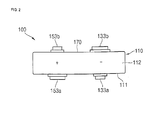
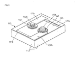
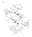
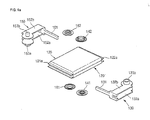
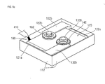
- the battery 100 includes a case 110, a pair of electrode assemblies 120, 120', a first terminal 130, first insulation gaskets 141 and 142, a second terminal 150, second insulation gaskets 161 and 162, and a cover 170.
- the case 110 has a substantially rectangular bottom surface 111, i.e., extending in an x-direction and a y-direction, and four sidewalls 112 folded in a substantially upward vertical direction, i.e., a z-direction, from the bottom surface 111.
- the four sidewalls 112 are also substantially rectangular shaped, and are connected to each other.
- an area of the bottom surface 111 is relatively larger than that of one of the sidewalls 112.
- the bottom surface 111 may be called a long side area and the sidewalls 112 may be called a short side area.
- the bottom surface 111 of the case 110 has a first throughhole 111a and a second throughhole 111b allowing the first terminal 130 and the second terminal 150, which will later be described, to pass therethrough to then protrude downwardly.
- an insulation layer (not shown) may be formed on the bottom surface 111 of the case 110 and inner surfaces of the sidewalls 112. The insulation layer prevents electrical shorts between the case 110 and the electrode assembly 120 to be described later, and between the first terminal 130 and the second terminal 150.
- the insulation layer may be made of at least one of EPDM (ethylene-propylene diene monomer) rubber, NBR (acrylonitrile butadiene rubber), IIR (isobutylene-isoprene rubber), butadiene rubber, SBR (styrene-butadiene rubber), which do not react to an electrolyte, or mixtures of two or more of these rubber materials, but embodiments of the invention are not limited thereto.
- the case 110 may be made of at least one selected from aluminum, an aluminum alloy, stainless steel, nickel plated steel, and equivalents thereof, but embodiments of the invention are not limited thereto.
- Each electrode assembly 120 is formed by winding or laminating a stacked structure including a first electrode plate 121 shaped of a thin plate or layer, a separator 123, and a second electrode plate 122, e.g., along the y direction, to form a jelly roll structure (see FIG. 4 ).
- each electrode assembly 120, 120' has a relatively wide long side area facing the bottom surface 111 of the case 110 or the cover 170 to be described later. Further, each electrode assembly 120, 120' has a relatively narrow short side area facing the four sidewalls 112 of the case 110.
- the first electrode plate 121 may act as a negative electrode
- second electrode plate 122 may act as a positive electrode, or vice versa. In other words, polarities of the aforementioned first and second electrode plates 121 and 122 may be reversed.
- Each first electrode plate 121 may be formed by coating a first electrode active material, e.g., graphite or carbon, on a first electrode collector formed of a metal foil, e.g., copper or nickel.
- the electrode plates 121 each include a first electrode uncoated portion 121a, i.e., a portion not coated with the first electrode active material.
- the first electrode uncoated portion 121a becomes a path of a current flowing between the first electrode plate 121 and the outside of the first electrode plates 121.
- the material of the first electrode plate 121 is not limited to the example materials described herein.
- the second electrode plates 122 may each be formed by coating a second electrode active material, e.g., a transition metal oxide, on a second electrode collector formed of a metal foil, e.g., aluminum.
- the second electrode plates 122 each include a second electrode uncoated portion 122a, i.e., a portion that is not coated with the second electrode active material.
- the second electrode uncoated portion 122a becomes a path of a current flowing between the second electrode plate 122 and the outside of the second electrode plate 122.
- the material of the second electrode plates 122 is not limited to the example materials described herein.
- separator 123 disposed between the first electrode plate 121 and the second electrode plate 122, serves to prevent electrical shorts and allows passage only to ions, e.g., lithium ions, in the electrolyte to be used in the battery cell 100.
- the separator 123 may be made of, for example, polyethylene, polypropylene, or a composite film of polyethylene and polypropylene.
- the material of the separator 123 is not limited to the example materials described herein.
- the first terminal 130 and the second terminal 150 are electrically connected to the first electrode plates 121 and the second electrode plates 122, respectively.
- the connection of each terminal 130, 150 is formed at a respective end of the electrode assemblies 120, 120'.
- the electrode assemblies 120, 120' are housed in the case 140 together with an electrolyte.
- the electrolyte may include an organic solvent, e.g., EC (ethylene carbonate), PC (propylene carbonate), DEC (diethyl carbonate), EMC (ethyl methyl carbonate), or DMC (dimethyl carbonate), and a lithium salt, e.g., LiPF 6 or LiBF 4 .
- the electrolyte may be a liquid, a solid, or a gel.
- any suitable number of assemblies may be provided, including just a single assembly.
- the first terminal 130 is electrically connected to the first electrode plates 121 of the electrode assemblies 120, 120'.
- the first terminal 130 may be made of at least one of copper, a copper alloy, and equivalents thereof, but embodiments are not limited thereto.
- the first terminal 130 includes a first collector portion 131, a pair of spaced-apart first extension portions 132a and 132b, and first bottom and top terminal regions 133a and 133b formed in the first extension portions 132a and 132b.
- the first bottom and top terminal regions 133a and 133b extend outwardly, i.e., in the z direction, from the first extension portions 132a and 132b and define connection formations.
- the first collector portion 131 is formed in a substantially bar shape having a predetermined length and is connected to the first uncoated portion 121a protruding from one end of each of the electrode assemblies 120, 120'.
- the first collector portion 131 is welded to the first uncoated portions 121a.
- the first uncoated portion 121a of the upper electrode assembly 120 is welded to a top surface of the first collector portion 131
- the first uncoated portion 121a of the lower electrode assembly 120 is welded to a bottom surface of the first collector portion 131.
- the pair of spaced-apart first extension portions 132a and 132b are each formed substantially in a plate shape having a constant area, and extend a predetermined length substantially toward the center of the battery cell 100 from the first collector portion 131.
- the first extension portions 132a and 132b are located along the long side area of the electrode assemblies 120, 120'.
- one first extension portion 132a of the pair of spaced-apart first extension portions 132a and 132b is along the bottom surface of the lower electrode assembly 120', and the other first extension portion 132b is along the top surface of the upper electrode assembly 120.
- the pair of first terminal regions 133a and 133b protrude outwardly from the first extension portions 132a and 132b, respectively.
- the first bottom terminal region 133a passes through the case 110 to then extend downwardly
- the first top terminal region 133b passes through the cover 170 to then extend upwardly.
- the pair of first terminal regions 133a and 133b have complementary connection formations.
- the first bottom terminal region 133a has a plug type structure
- the first top terminal region 133b has a socket type structure.
- the first insulation gasket 141 passes through the first throughhole 111a provided in the case 110 while substantially covering the first bottom terminal region 133a. Therefore, the first bottom terminal region 133a and the case 110 are electrically insulated from each other. In addition, the first insulation gasket 141 is closely adhered to the bottom surface, i.e., the long side area, of the lower electrode assembly 120'.
- the first insulation gasket 142 covers the first top terminal region 133b and passes through a first throughhole 170a provided in the cover 170. Therefore, the first top terminal region 133b and the cover 170 are electrically insulated from each other. In addition, the first insulation gasket 142 is closely adhered to the top surface, that is, the long side area, of the upper electrode assembly 120.
- the second terminal 150 is electrically connected to the second electrode plates 122 of the electrode assemblies 120, 120'.
- the second terminal 150 is made of at least of aluminum, an aluminum alloy, and equivalents thereof, but embodiments are not limited thereto.
- the second terminal 150 includes a second collector portion 151, a pair of spaced-apart second extension portions 152a and 152b, and second bottom and top terminal regions 153a and 153b formed in the second extending regions 152a and 152b.
- the second bottom and top terminal regions 153a and 153b extend outwardly, i.e., in the z direction, from the second extending regions 152a and 152b and define connection formations.
- the second collector portion 151 is formed in a substantially bar shape having a predetermined length and is connected to a second uncoated portions 122a protruding from the other end of the electrode assemblies 120, 120'.
- the second collector portion 151 is welded to the second uncoated portions 122a.
- the second uncoated portion 122a of the upper electrode assembly 120 is welded to a top surface of the second collector portion 151
- the second uncoated portion 122a of the lower electrode assembly 120 is welded to a bottom surface of the second collector portion 151.
- the pair of spaced-apart second extension portions 152a and 152b are each formed substantially in a plate shape having a constant area, and extend a predetermined length substantially toward the center of the battery cell 100 from the second collector portion 151.
- the second extension portions 152a and 152b are located along the long side area of the electrode assembly 120.
- one second extension portion 152a of the pair of spaced-apart second extension portion 152a and 152b is along the bottom surface of the lower electrode assembly 120', and the other second extension portion 152b is along the top surface of the upper electrode assembly 120.
- the pair of second terminal regions 153a and 153b outwardly protrude from the second extending regions 152a and 152b, respectively, along the z direction.
- the second bottom terminal region 153a passes through the case 110 to then extend downwardly in the z direction
- the second top terminal region 153b passes through the case 110 to then extend upwardly along the z direction.
- the pair of second terminal regions 153a and 153b have complementary connection formations. More specifically, the second bottom terminal region 153a has a socket type structure, and the second top terminal region 153b has a plug type structure. Further, the first and second bottom terminal regions 133a, 153a have complementary connection formations and the first and second top terminal regions 133b, 153b have complementary connection formations.
- the second insulation gasket 161 passes through the second throughhole 111b provided in the case 110 while substantially covering the second bottom terminal region 153a. Therefore, the second bottom terminal region 153a and the case 110 are electrically insulated from each other. In addition, the second insulation gasket 161 is closely adhered to the bottom surface, i.e., the long side area, of the lower electrode assembly 120'.
- the second insulation gasket 162 passes through the second throughhole 170b provided in the cover 170 while substantially covering the second top terminal region 153b. Therefore, the second top terminal region 153b and the cover 170 are electrically insulated from each other. In addition, the second insulation gasket 162 is closely adhered to the bottom surface, i.e., the long side area, of the upper electrode assembly 120.
- the cover 170 is formed in a substantially rectangular plate shape and covers the case 110. That is to say, four sides of the cover 170 are coupled to the four sidewalls 112 of the case 110, respectively, e.g., by laser welding. Therefore, the electrode assemblies 120, 120' the first terminal 130, the first insulation gaskets 141 and 142, the second terminal 150, the second insulation gaskets 161 and 162, and an electrolyte (not shown) are hermetically sealed by the case 110 and the cover 170.
- the cover 170 includes the first throughhole 170a and the second throughhole 170b allowing the first terminal 130 and the second terminal 150 to pass therethrough.
- the first insulation gasket 142 is disposed in the first throughhole 170a, and the second insulation gasket 162 is disposed in the second throughhole 170b.
- the case 110 may include an insulation layer (not shown) formed on the bottom surface thereof facing the electrode assembly 120. The insulation layer prevents electrical shorts between the cover 170 and the electrode assembly 120 and between the first terminal 130 and the second terminal 150.
- the insulation layer may be made of at least one of EPDM (ethylene-propylene diene monomer) rubber, NBR (acrylonitrile butadiene rubber), IIR (isobutylene-isoprene rubber), butadiene rubber, SBR (styrene-butadiene rubber), which do not react to an electrolyte, or mixtures of two or more of these rubber materials, but embodiments are not limited thereto.
- the cover 170 may be made of at least one of aluminum, an aluminum alloy, stainless steel, nickel plated steel, and equivalents thereof, but embodiments are not limited thereto.
- FIGS. 5A and 5B illustrate side views of states in which a battery pack 200 is yet to be assembled and the battery pack 200 is assembled using a battery according to an embodiment.
- FIG. 5C illustrates a partially enlarged sectional view of FIG. 5B .
- a plurality of battery cells 100 can be connected in series and/or parallel to each other without using a bus bar.
- four left battery cells 100L may be connected in parallel
- four right battery cells 100R may be connected in parallel.
- left battery cells 100L and right battery cells 100R may be connected in series to each other.
- the first bottom terminal region 133a of one battery cell 100 is coupled to the first top terminal region 133b of an adjacent battery cell 100.
- the second bottom terminal region 153a of one battery cell 100 is coupled to the second top terminal region 153b of an adjacent battery cell 100. In such a manner, a plurality of battery cells 100 of the four left battery cells 100L may be connected in parallel to each other.
- the first bottom terminal region 133a of one battery cell 100 is coupled to the first top terminal region 133b of an adjacent battery cell 100.
- the second bottom terminal region 153a of one battery cell 100 is coupled to the second top terminal region 153b of an adjacent battery cell 100. In such a manner, a plurality of battery cells 100 of the four right battery cells 100R may be connected in parallel to each other.
- only one pair of terminal connection formations in opposing faces of battery cells to be connected need be coupled.
- only one second top terminal region 153b in a leftmost battery cell of the right battery cells 100R and one first top terminal region 133b in a rightmost battery cell of the left battery cells 100L are electrically connected to each other.
- An insulator 210 may therefore be provided between another first top terminal region 133b of the leftmost battery cell in the right battery cells 100R and another second terminal top region 153b of the rightmost battery cell of the left battery cells 100L, such that these regions are not electrically connected to each other, as illustrated in detail in FIG. 5C .
- the insulator 210 may be at least one selected from a general insulating adhesive, an insulating film, an insulating tape, and equivalents thereof, but embodiments are not limited thereto. In such a manner, the right battery cells 100R and the left battery cells 100L are connected in series to each other.
- FIGS. 6A and 6B illustrate side views of states in which a battery pack 300 is yet to be assembled and the battery pack 300 is assembled using a battery according to another embodiment.
- FIG. 6C illustrates a partially enlarged sectional view of FIG. 6B .
- a plurality of battery cells 100 can be connected in series and/or parallel to each other without using a bus bar.
- four left battery cells 100L' may be connected in parallel and four right battery cells 100R' may be connected in parallel.
- left battery cells 100L' and right battery cells 100R' may be connected in series to each other.
- the second top terminal region 153b of a leftmost battery cell of the right battery cells 100R' and the first top terminal region 133b of rightmost battery cell of the left battery cells 100L' are connected to each other.
- another first top terminal region is not on the leftmost battery cell of the right battery cell 100R' and/or another second top terminal region is not on the rightmost battery cell of the left battery cells 100L'.
- the right battery cells 100R' and the left battery cells 100L' may be connected in series to each other without an insulator (210 of FIG. 5C ) while still preventing terminals from being electrically connected to each other.
- FIG. 7 illustrates an equivalent circuit diagram of a battery pack according to an embodiment of the invention.
- the battery pack according to the illustrated embodiment has the same circuit configuration as that of the battery pack shown in FIG. 5B or 6B , in which four left battery cells are connected in parallel, four right battery cells are connected in parallel, and the left battery cells and the right battery cells are connected in series to each other.
- the battery pack may have various electrical connection structures in addition to the above-described structure, such that embodiments are not limited to those illustrated herein.
- FIG. 8 illustrates a flowchart of a method of manufacturing a battery cell according to an embodiment of the invention.
- the method of manufacturing a battery cell according to the embodiment includes connecting an electrode assembly and a terminal (S1), housing the electrode assembly and the terminal in a case (S2), injecting an electrolyte (S3), and combining a cover (S4).
- FIGS. 9A through 9D illustrate perspective views in stages of a method of manufacturing a battery cell according to an embodiment.
- FIG. 9A in connecting an electrode assembly and a terminal (S1), at least one electrode assembly 120 is prepared, and a first terminal 130 and a second terminal 150 are electrically connected to the electrode assembly 120.
- the first terminal 130 includes a first collector portion 131, a pair of spaced-apart first extension portions 132a and 132b, and first terminal regions 133a and 133b formed in the first extension portions 132a and 132b and extending outwardly, respectively.
- the first collector portion 131 of the first terminal 130 is electrically connected to first uncoated portions 121a extending from first electrode plates 121 of the electrode assemblies 120, 120'.
- the first uncoated portions 121a may be welded to the first collector portion 131.
- the second terminal 150 includes a second collector portion 151, a pair of spaced-apart second extension portions 152a and 152b, and second terminal regions 153a and 153b formed in the second extension portions 152a and 152b and extending outwardly, respectively.
- the second collector portion 151 of the second terminal 150 is electrically connected to second uncoated portions 122a extending from the second electrode plates 122 of the electrode assemblies 120, 120'.
- the second uncoated portions 122a may be welded to the second collector region 151.
- the electrode assemblies 120, 120' the first terminal 130 and the second terminal 150 are housed in the case 110 having a bottom surface 111 and four sidewalls 112.
- First insulation gaskets 141 and 142 are coupled to a pair of first terminal regions 133a and 133b of the first terminal 130
- second insulation gaskets 161 and 162 are coupled to a pair of second terminal regions 153a and 153b of the second terminal 150.
- first terminal region 133a and the first insulation gasket 141, and the second terminal region 153a and the second insulation gasket 161, positioned under the electrode assembly 120, are coupled to a first throughhole 111a and a second throughhole 111b provided on the bottom surface 111 of the case 110, respectively.
- a predetermined amount of the electrolyte 180 is injected into the case 110 using an electrolyte injection tool 410.
- the electrolyte 180 may be provided in a state in which it is impregnated into the electrode assemblies 120, 120'. In such a case, injecting an electrolyte (S3) may be omitted.
- injecting an electrolyte (S3) may be performed after combining a cover (S4), which will later be described.
- a separate opening (not shown) may be previously formed in the case 110 or the cover 170, and an electrolyte may be injected through the opening. After the electrolyte is injected, the opening is closed using a plug (not shown).
- the cover 170 is secured to the case 110.
- the first terminal region 133b and the first insulation gasket 142, and the second terminal region 153b and the second insulation gasket 162, positioned on the electrode assemblies 120, 120' are coupled to a first throughhole 170a and a second throughhole 170b provided on the cover 170, respectively.
- boundary portions formed by four edges of the cover 170 and four sidewalls 112 of the case 110 may be secured, e.g., welded by laser beam 511 using a laser welding tool 510, thereby combining the cover 170 with the case 110.
- an ultra welding tool for example, may also be used.
- the cover 170 may also be secured to the case 110 by a separate adhesive. Thus, combining of the case 110 and the cover 170 is not limited to those examples illustrated herein.
- FIG. 10A illustrates a perspective view of a battery according to another embodiment of the invention and FIG. 10B illustrates a state in which a battery pack is assembled using the battery shown in FIG. 10A .
- a battery 400c according to the invention may have a substantially cylindrical shape.
- the battery 400c includes a substantially cylindrical case 410, one first terminal region 433a and another first terminal region 433b, and one second terminal region 453a and another second terminal region 453b.
- the one first terminal region 433a and the other first terminal region 433b include connection formations having mutually different shapes that are located at different positions while having the same polarity, for example, a first polarity (e.g., a negative electrode).
- One first terminal region 433a has a socket type structure
- the other first terminal region 433b has a plug type structure. Consequently, the structures of the one first terminal region 433a and the other first terminal region 433b are complementary.
- the one first terminal region 433a and the other first terminal region 433b are positioned on respectively opposite aspects of the cell.
- the one second terminal region 453a and the other second terminal region 453b include connection formations having mutually different shapes that are located at different positions while having the same polarity, for example, a second polarity (e.g., a positive electrode).
- One second terminal region 453a has a socket type structure
- the other second terminal region 453b has a plug type structure. Consequently, the structures of the one second terminal region 453a and the other second terminal region 453b are complementary.
- the one second terminal region 453a and the other second terminal region 453b are positioned on respectively opposite aspects of the cell.
- the one first terminal region 433a and the one second terminal region 453a also have complementary structures and are oriented in the same direction.
- the battery pack 400p may include a plurality of batteries 400c, each as shown in FIG. 10A and connected in series and/or parallel to each other.
- FIG. 10B shows that the plurality of batteries 400c are connected in series to each other.
- one first terminal region 433a of one of the plurality of batteries may be mechanically, electrically connected to one second terminal region 453a of another battery.
- the other second terminal region 453b of the latter battery may be mechanically, electrically connected to the other first terminal region 433b of still another battery.
- the plurality of batteries may be connected to each other, thereby forming the battery pack 400p.
- FIG. 11A illustrates a perspective view of a battery according to another embodiment of the invention and FIG. 11B illustrates a state in which a battery pack is assembled using the battery shown in FIG. 11A .
- a battery 500c according to the ivnention may have a substantially prismatic (square or rectangular) shape.
- the battery 500c includes a substantially prismatic case 510, one first terminal region 533a and another first terminal region 533b, and one second terminal region 553a and another second terminal region 553b.
- the one first terminal region 533a and the other first terminal region 533b have different shapes and are located at different positions while having the same polarity, for example, a first polarity (e.g., a negative electrode).
- a first polarity e.g., a negative electrode
- the one first terminal region 533a and the other first terminal region 533b are positioned on different aspects of the battery cell. That is to say, a surface where the one first terminal region 533a is formed is substantially perpendicular to a surface where the other first terminal region 533b is formed.
- the one second terminal region 553a and the other second terminal region 553b also have different shapes and are located at different positions while having the same polarity, for example, a second polarity (e.g., a positive electrode).
- a second polarity e.g., a positive electrode
- the one second terminal region 553a and the other second terminal region 553b are positioned on different aspects of the battery cell. That is to say, a surface where the one second terminal region 553a is formed is substantially perpendicular to a surface where the other second terminal region 553b is formed.
- the battery pack 500p may include a plurality of batteries 500c, each as shown in FIG. 11A , that are connected in series and/or parallel to each other.
- a one first terminal region 533a of one of the plurality of batteries may be mechanically, electrically connected to a one second terminal region 553a of another battery.
- the other second terminal region 553b of the latter battery may be mechanically, electrically connected to the other first terminal region 533b of still another battery.
- FIG. 12A illustrates a perspective view of a battery according to another embodiment of the invention and FIG. 12B illustrates a state in which a battery pack is assembled using the battery shown in FIG. 12A .
- a battery 600c according to the invention may be a thin prismatic battery.
- the battery 600c is substantially the same as the battery 100 shown in FIG. 1 , except for its terminal regions. That is to say, the battery 600c includes a first terminal region 633 formed on one surface of a case 610 and a second terminal region 653 formed on the other surface of the case 610.
- first terminal region 633 and the second terminal region 653 have different polarities and different shapes.
- first terminal region 633 may be a positive electrode and the second terminal region 653 may be a negative electrode.
- first terminal region 633 has a plug type structure
- second terminal region 653 has a socket type structure. Consequently, the structures of the first terminal region 633 and the second terminal region 653 are complementary.
- the battery pack 600p may include a plurality of batteries 600c, each shown in FIG. 12A , connected in series to each other.
- the first terminal region 633 of one of the plurality of batteries may be mechanically, electrically connected to the second terminal region 653 of another battery.
- the second terminal region 653 of the latter battery may be mechanically, electrically connected to the first terminal region 633 of still another battery.
- the plurality of batteries may be connected in series to each other, thereby forming the battery pack 600p.
- a battery cell according to embodiments and a battery pack using the same may have a plurality of battery cells connected in series and/or parallel to each other by mating protruding terminal regions, instead of using a bus bar.
- the above-described battery cells and manufacturing method thereof are provided for illustration only and embodiments are not limited to the battery cells and manufacturing method illustrated hereinabove.
- a variety of safety devices including a safety vent, an overcharge preventing device, a fuse, and so on, may be additionally provided in the battery cell.
- the terminals provided in the battery cell having plug and receptacle type structures may be modified in various forms of mating terminals that are not illustrated herein, such that the foregoing disclosure does not limit the terminal structures to those illustrated herein.
Abstract
a case;
an electrode assembly located within the case and comprising first and second electrodes;
a first terminal electrically connected with the first electrode; and
a second terminal electrically connected with the second electrode; wherein
the first and second terminals project through the case; and
one of the first and second terminals comprises first and second connection formations; wherein
the first and second connection formations have mutually different shapes and are located on respectively different aspects of the case.
Description
- The present invention relates to a battery cell.
- Unlike a primary battery that is not chargeable, a secondary battery is rechargeable. Small capacity secondary batteries, each having a single unit cell, are generally used for various portable electronic devices, e.g., phones, laptop computers, and camcorders. Large capacity secondary batteries, each having a plurality of unit cells, are generally used as the power source for driving motors, such as those in electric scooters, hybrid electric vehicles, or electric motor vehicles.
- Secondary batteries are manufactured in various shapes exemplified by cylindrical and prismatic types. Such batteries are typically constructed by installing an electrode assembly including a positive electrode plate, a negative electrode plate and a separator serving as an insulator interposed therebetween, and an electrolyte in a can and fitting a cap plate. A positive electrode terminal and a negative electrode terminal are connected to the electrode assembly, and these terminals are exposed to the outside via the cap plate.
- The above and other features and advantages will become more apparent to those of ordinary skill in the art upon referring to the following embodiments of the invention which are described with reference to the attached drawings, in which:
-
FIG. 1 illustrates a perspective view of a battery according to an embodiment of the invention; -
FIG. 2 illustrates a side view of the battery shown inFIG. 1 ; -
FIG. 3 illustrates a perspective view of a state in which a cover is removed from the battery shown inFIG. 1 ; -
FIG. 4 illustrates an exploded perspective view of the battery shown inFIG. 1 ; -
FIGS. 5A and 5B illustrate side views of states in which a battery pack is yet to be assembled and a battery pack is assembled using a battery according to an embodiment of the invention, andFIG. 5C is a partially enlarged sectional view ofFIG. 5B ; -
FIGS. 6A and 6B illustrate side views of states in which a battery pack is yet to be assembled and a battery pack is assembled using a battery according to another embodiment of the invention, andFIG. 6C is a partially enlarged sectional view ofFIG. 6B ; -
FIG. 7 illustrates an equivalent circuit diagram of a battery pack according to an embodiment of the invention; -
FIG. 8 illustrates a flowchart of a method of manufacturing a battery cell according to an embodiment of the invention; -
FIGS. 9A through 9D illustrate perspective views of the method of manufacturing a battery cell according to an embodiment of the invention; -
FIG. 10A illustrates a perspective view of a battery according to another embodiment of the invention andFIG. 10B illustrates a state in which a plurality of battery cells are connected to each other; -
FIG. 11A illustrates a perspective view of a battery according to another embodiment of the invention andFIG. 11B illustrates a state in which a plurality of battery cells are connected to each other; and -
FIG. 12A illustrates a perspective view of a battery according to another embodiment of the invention andFIG. 12B illustrates a state in which a plurality of battery cells are connected to each other. - Embodiments of the invention will now be described more fully hereinafter with reference to the accompanying drawings; however, the invention may be embodied in different forms and should not be construed as limited to the embodiments set forth herein. Rather, these embodiments are provided so that this disclosure will be thorough and complete, and will fully convey the scope of the invention to those skilled in the art.
- Throughout the specification, the same reference numerals refer to the same elements. Further, when it is stated herein that one part is "connected" to another part, the one part may be directly connected to the other part, or the one part and the other part may be electrically connected at respective sides of another device or conductive element.
- It will also be understood that, although the terms "first" and "second" etc. may be used herein to describe various elements, structures, components, regions, layers and/or sections, these elements, structures, components, regions, layers and/or sections should not be limited by these terms. These terms are only used to distinguish one element, structure, component, region, layer and/or section from another element, structure, component, region, layer and/or section. Thus, a first element, structure, component, region, layer or section discussed below could be termed a second element, structure, component, region, layer or section without departing from the scope of the invention.
- Spatially relative terms, such as "beneath," "below," "lower," "bottom," "above," "upper," "top," and the like, may be used herein for ease of description to describe one element or feature relationship to another element(s) or feature(s) as illustrated in the figures. It will be understood that the spatially relative terms are intended to encompass different orientations of the device in use or operation in addition to the orientation depicted in the figures. For example, if the device in the figures is turned over (or upside down), elements or layers described as "below" or "beneath" other elements or layers would then be oriented "above" the other elements or layers. Thus, the term "below" can encompass both an orientation of above and below. The device may be otherwise oriented (rotated 90 degrees or at other orientations) and the spatially relative descriptors used herein interpreted accordingly.
- Referring to
FIGS. 1 through 4 , thebattery 100 includes acase 110, a pair ofelectrode assemblies 120, 120', afirst terminal 130,first insulation gaskets second terminal 150,second insulation gaskets cover 170. - The
case 110 has a substantiallyrectangular bottom surface 111, i.e., extending in an x-direction and a y-direction, and foursidewalls 112 folded in a substantially upward vertical direction, i.e., a z-direction, from thebottom surface 111. Here, the foursidewalls 112 are also substantially rectangular shaped, and are connected to each other. In addition, an area of thebottom surface 111 is relatively larger than that of one of thesidewalls 112. In some cases, thebottom surface 111 may be called a long side area and thesidewalls 112 may be called a short side area. Thebottom surface 111 of thecase 110 has afirst throughhole 111a and asecond throughhole 111b allowing thefirst terminal 130 and thesecond terminal 150, which will later be described, to pass therethrough to then protrude downwardly. - Further, an insulation layer (not shown) may be formed on the
bottom surface 111 of thecase 110 and inner surfaces of thesidewalls 112. The insulation layer prevents electrical shorts between thecase 110 and theelectrode assembly 120 to be described later, and between thefirst terminal 130 and thesecond terminal 150. - More specifically, the insulation layer may be made of at least one of EPDM (ethylene-propylene diene monomer) rubber, NBR (acrylonitrile butadiene rubber), IIR (isobutylene-isoprene rubber), butadiene rubber, SBR (styrene-butadiene rubber), which do not react to an electrolyte, or mixtures of two or more of these rubber materials, but embodiments of the invention are not limited thereto. The
case 110 may be made of at least one selected from aluminum, an aluminum alloy, stainless steel, nickel plated steel, and equivalents thereof, but embodiments of the invention are not limited thereto. - Each
electrode assembly 120 is formed by winding or laminating a stacked structure including afirst electrode plate 121 shaped of a thin plate or layer, aseparator 123, and asecond electrode plate 122, e.g., along the y direction, to form a jelly roll structure (seeFIG. 4 ). In addition, eachelectrode assembly 120, 120' has a relatively wide long side area facing thebottom surface 111 of thecase 110 or thecover 170 to be described later. Further, eachelectrode assembly 120, 120' has a relatively narrow short side area facing the foursidewalls 112 of thecase 110. In addition, in each case thefirst electrode plate 121 may act as a negative electrode, andsecond electrode plate 122 may act as a positive electrode, or vice versa. In other words, polarities of the aforementioned first andsecond electrode plates - Each
first electrode plate 121 may be formed by coating a first electrode active material, e.g., graphite or carbon, on a first electrode collector formed of a metal foil, e.g., copper or nickel. Theelectrode plates 121 each include a first electrode uncoatedportion 121a, i.e., a portion not coated with the first electrode active material. The first electrodeuncoated portion 121a becomes a path of a current flowing between thefirst electrode plate 121 and the outside of thefirst electrode plates 121. However, the material of thefirst electrode plate 121 is not limited to the example materials described herein. - The
second electrode plates 122 may each be formed by coating a second electrode active material, e.g., a transition metal oxide, on a second electrode collector formed of a metal foil, e.g., aluminum. Thesecond electrode plates 122 each include a second electrodeuncoated portion 122a, i.e., a portion that is not coated with the second electrode active material. The second electrodeuncoated portion 122a becomes a path of a current flowing between thesecond electrode plate 122 and the outside of thesecond electrode plate 122. However, the material of thesecond electrode plates 122 is not limited to the example materials described herein. - In each
electrode assembly 120, 120',separator 123, disposed between thefirst electrode plate 121 and thesecond electrode plate 122, serves to prevent electrical shorts and allows passage only to ions, e.g., lithium ions, in the electrolyte to be used in thebattery cell 100. Theseparator 123 may be made of, for example, polyethylene, polypropylene, or a composite film of polyethylene and polypropylene. However, the material of theseparator 123 is not limited to the example materials described herein. - The
first terminal 130 and thesecond terminal 150 are electrically connected to thefirst electrode plates 121 and thesecond electrode plates 122, respectively. The connection of each terminal 130, 150 is formed at a respective end of theelectrode assemblies 120, 120'. - The
electrode assemblies 120, 120' are housed in the case 140 together with an electrolyte. The electrolyte may include an organic solvent, e.g., EC (ethylene carbonate), PC (propylene carbonate), DEC (diethyl carbonate), EMC (ethyl methyl carbonate), or DMC (dimethyl carbonate), and a lithium salt, e.g., LiPF6 or LiBF4. In addition, the electrolyte may be a liquid, a solid, or a gel. - Although a stack of two
electrode assemblies 120 and 120' is provided in this embodiment of the invention, any suitable number of assemblies may be provided, including just a single assembly. - The
first terminal 130 is electrically connected to thefirst electrode plates 121 of theelectrode assemblies 120, 120'. Thefirst terminal 130 may be made of at least one of copper, a copper alloy, and equivalents thereof, but embodiments are not limited thereto. - More specifically, the
first terminal 130 includes afirst collector portion 131, a pair of spaced-apartfirst extension portions terminal regions first extension portions terminal regions first extension portions - The
first collector portion 131 is formed in a substantially bar shape having a predetermined length and is connected to the firstuncoated portion 121a protruding from one end of each of theelectrode assemblies 120, 120'. Thefirst collector portion 131 is welded to the firstuncoated portions 121a. In particular, the firstuncoated portion 121a of theupper electrode assembly 120 is welded to a top surface of thefirst collector portion 131, and the firstuncoated portion 121a of thelower electrode assembly 120 is welded to a bottom surface of thefirst collector portion 131. - The pair of spaced-apart
first extension portions battery cell 100 from thefirst collector portion 131. In addition, thefirst extension portions electrode assemblies 120, 120'. In particular, onefirst extension portion 132a of the pair of spaced-apartfirst extension portions first extension portion 132b is along the top surface of theupper electrode assembly 120. - The pair of first
terminal regions first extension portions bottom terminal region 133a passes through thecase 110 to then extend downwardly, and the first topterminal region 133b passes through thecover 170 to then extend upwardly. - The pair of first
terminal regions bottom terminal region 133a has a plug type structure, and the first topterminal region 133b has a socket type structure. - The
first insulation gasket 141 passes through the first throughhole 111a provided in thecase 110 while substantially covering the firstbottom terminal region 133a. Therefore, the firstbottom terminal region 133a and thecase 110 are electrically insulated from each other. In addition, thefirst insulation gasket 141 is closely adhered to the bottom surface, i.e., the long side area, of the lower electrode assembly 120'. - The
first insulation gasket 142 covers the first topterminal region 133b and passes through a first throughhole 170a provided in thecover 170. Therefore, the first topterminal region 133b and thecover 170 are electrically insulated from each other. In addition, thefirst insulation gasket 142 is closely adhered to the top surface, that is, the long side area, of theupper electrode assembly 120. - The
second terminal 150 is electrically connected to thesecond electrode plates 122 of theelectrode assemblies 120, 120'. Thesecond terminal 150 is made of at least of aluminum, an aluminum alloy, and equivalents thereof, but embodiments are not limited thereto. - More specifically, the
second terminal 150 includes asecond collector portion 151, a pair of spaced-apartsecond extension portions terminal regions regions terminal regions regions - The
second collector portion 151 is formed in a substantially bar shape having a predetermined length and is connected to a seconduncoated portions 122a protruding from the other end of theelectrode assemblies 120, 120'. Thesecond collector portion 151 is welded to the seconduncoated portions 122a. In particular, the seconduncoated portion 122a of theupper electrode assembly 120 is welded to a top surface of thesecond collector portion 151, and the seconduncoated portion 122a of thelower electrode assembly 120 is welded to a bottom surface of thesecond collector portion 151. - The pair of spaced-apart
second extension portions battery cell 100 from thesecond collector portion 151. In addition, thesecond extension portions electrode assembly 120. In particular, onesecond extension portion 152a of the pair of spaced-apartsecond extension portion second extension portion 152b is along the top surface of theupper electrode assembly 120. - The pair of second
terminal regions regions bottom terminal region 153a passes through thecase 110 to then extend downwardly in the z direction, and the second topterminal region 153b passes through thecase 110 to then extend upwardly along the z direction. - The pair of second
terminal regions bottom terminal region 153a has a socket type structure, and the second topterminal region 153b has a plug type structure. Further, the first and secondbottom terminal regions terminal regions - The
second insulation gasket 161 passes through thesecond throughhole 111b provided in thecase 110 while substantially covering the secondbottom terminal region 153a. Therefore, the secondbottom terminal region 153a and thecase 110 are electrically insulated from each other. In addition, thesecond insulation gasket 161 is closely adhered to the bottom surface, i.e., the long side area, of the lower electrode assembly 120'. - The
second insulation gasket 162 passes through thesecond throughhole 170b provided in thecover 170 while substantially covering the second topterminal region 153b. Therefore, the second topterminal region 153b and thecover 170 are electrically insulated from each other. In addition, thesecond insulation gasket 162 is closely adhered to the bottom surface, i.e., the long side area, of theupper electrode assembly 120. - The
cover 170 is formed in a substantially rectangular plate shape and covers thecase 110. That is to say, four sides of thecover 170 are coupled to the foursidewalls 112 of thecase 110, respectively, e.g., by laser welding. Therefore, theelectrode assemblies 120, 120' thefirst terminal 130, thefirst insulation gaskets second terminal 150, thesecond insulation gaskets case 110 and thecover 170. In addition, thecover 170 includes the first throughhole 170a and thesecond throughhole 170b allowing thefirst terminal 130 and thesecond terminal 150 to pass therethrough. Thefirst insulation gasket 142 is disposed in the first throughhole 170a, and thesecond insulation gasket 162 is disposed in thesecond throughhole 170b. Further, thecase 110 may include an insulation layer (not shown) formed on the bottom surface thereof facing theelectrode assembly 120. The insulation layer prevents electrical shorts between thecover 170 and theelectrode assembly 120 and between thefirst terminal 130 and thesecond terminal 150. - The insulation layer may be made of at least one of EPDM (ethylene-propylene diene monomer) rubber, NBR (acrylonitrile butadiene rubber), IIR (isobutylene-isoprene rubber), butadiene rubber, SBR (styrene-butadiene rubber), which do not react to an electrolyte, or mixtures of two or more of these rubber materials, but embodiments are not limited thereto. The
cover 170 may be made of at least one of aluminum, an aluminum alloy, stainless steel, nickel plated steel, and equivalents thereof, but embodiments are not limited thereto. -
FIGS. 5A and 5B illustrate side views of states in which abattery pack 200 is yet to be assembled and thebattery pack 200 is assembled using a battery according to an embodiment.FIG. 5C illustrates a partially enlarged sectional view ofFIG. 5B . - As shown in
FIGS. 5A and 5B , in thebattery pack 200, a plurality ofbattery cells 100 can be connected in series and/or parallel to each other without using a bus bar. As shown inFIGS. 5A and 5B , fourleft battery cells 100L may be connected in parallel, and fourright battery cells 100R may be connected in parallel. In addition,left battery cells 100L andright battery cells 100R may be connected in series to each other. - More specifically, amongst the four
left battery cells 100L, the firstbottom terminal region 133a of onebattery cell 100 is coupled to the first topterminal region 133b of anadjacent battery cell 100. In addition, the secondbottom terminal region 153a of onebattery cell 100 is coupled to the second topterminal region 153b of anadjacent battery cell 100. In such a manner, a plurality ofbattery cells 100 of the fourleft battery cells 100L may be connected in parallel to each other. - In addition, amongst the four
right battery cells 100R, the firstbottom terminal region 133a of onebattery cell 100 is coupled to the first topterminal region 133b of anadjacent battery cell 100. In addition, the secondbottom terminal region 153a of onebattery cell 100 is coupled to the second topterminal region 153b of anadjacent battery cell 100. In such a manner, a plurality ofbattery cells 100 of the fourright battery cells 100R may be connected in parallel to each other. - In a structure in which the
left battery cells 100L and theright battery cells 100R are connected in series to each other, only one pair of terminal connection formations in opposing faces of battery cells to be connected, need be coupled. For example, only one second topterminal region 153b in a leftmost battery cell of theright battery cells 100R and one first topterminal region 133b in a rightmost battery cell of theleft battery cells 100L are electrically connected to each other. Aninsulator 210 may therefore be provided between another first topterminal region 133b of the leftmost battery cell in theright battery cells 100R and another second terminaltop region 153b of the rightmost battery cell of theleft battery cells 100L, such that these regions are not electrically connected to each other, as illustrated in detail inFIG. 5C . Theinsulator 210 may be at least one selected from a general insulating adhesive, an insulating film, an insulating tape, and equivalents thereof, but embodiments are not limited thereto. In such a manner, theright battery cells 100R and theleft battery cells 100L are connected in series to each other. -
FIGS. 6A and 6B illustrate side views of states in which abattery pack 300 is yet to be assembled and thebattery pack 300 is assembled using a battery according to another embodiment.FIG. 6C illustrates a partially enlarged sectional view ofFIG. 6B . - As shown in
FIGS. 6A and 6B , in thebattery pack 300, a plurality ofbattery cells 100 can be connected in series and/or parallel to each other without using a bus bar. As shown inFIGS. 6A and 6B , fourleft battery cells 100L' may be connected in parallel and fourright battery cells 100R' may be connected in parallel. In addition,left battery cells 100L' andright battery cells 100R' may be connected in series to each other. - As shown in
FIGS. 6A, 6B and6C , the second topterminal region 153b of a leftmost battery cell of theright battery cells 100R' and the first topterminal region 133b of rightmost battery cell of theleft battery cells 100L' are connected to each other. However, another first top terminal region is not on the leftmost battery cell of theright battery cell 100R' and/or another second top terminal region is not on the rightmost battery cell of theleft battery cells 100L'. In such a manner, theright battery cells 100R' and theleft battery cells 100L' may be connected in series to each other without an insulator (210 ofFIG. 5C ) while still preventing terminals from being electrically connected to each other. -
FIG. 7 illustrates an equivalent circuit diagram of a battery pack according to an embodiment of the invention. As shown inFIG. 7 , the battery pack according to the illustrated embodiment has the same circuit configuration as that of the battery pack shown inFIG. 5B or6B , in which four left battery cells are connected in parallel, four right battery cells are connected in parallel, and the left battery cells and the right battery cells are connected in series to each other. According to the illustrated embodiment, the battery pack may have various electrical connection structures in addition to the above-described structure, such that embodiments are not limited to those illustrated herein. -
FIG. 8 illustrates a flowchart of a method of manufacturing a battery cell according to an embodiment of the invention. As shown inFIG. 8 , the method of manufacturing a battery cell according to the embodiment includes connecting an electrode assembly and a terminal (S1), housing the electrode assembly and the terminal in a case (S2), injecting an electrolyte (S3), and combining a cover (S4). -
FIGS. 9A through 9D illustrate perspective views in stages of a method of manufacturing a battery cell according to an embodiment. As shown inFIG. 9A , in connecting an electrode assembly and a terminal (S1), at least oneelectrode assembly 120 is prepared, and afirst terminal 130 and asecond terminal 150 are electrically connected to theelectrode assembly 120. - Here, the
first terminal 130 includes afirst collector portion 131, a pair of spaced-apartfirst extension portions terminal regions first extension portions first collector portion 131 of thefirst terminal 130 is electrically connected to firstuncoated portions 121a extending fromfirst electrode plates 121 of theelectrode assemblies 120, 120'. For example, the firstuncoated portions 121a may be welded to thefirst collector portion 131. - The
second terminal 150 includes asecond collector portion 151, a pair of spaced-apartsecond extension portions terminal regions second extension portions second collector portion 151 of thesecond terminal 150 is electrically connected to seconduncoated portions 122a extending from thesecond electrode plates 122 of theelectrode assemblies 120, 120'. For example, the seconduncoated portions 122a may be welded to thesecond collector region 151. - As shown in
FIG. 9B , in housing the electrode assembly and the terminal in a case (S2), theelectrode assemblies 120, 120' thefirst terminal 130 and thesecond terminal 150 are housed in thecase 110 having abottom surface 111 and foursidewalls 112.First insulation gaskets terminal regions first terminal 130, andsecond insulation gaskets terminal regions second terminal 150. In addition, the firstterminal region 133a and thefirst insulation gasket 141, and the secondterminal region 153a and thesecond insulation gasket 161, positioned under theelectrode assembly 120, are coupled to afirst throughhole 111a and asecond throughhole 111b provided on thebottom surface 111 of thecase 110, respectively. - As shown in
FIG. 9C , in injecting an electrolyte (S3), a predetermined amount of the electrolyte 180 is injected into thecase 110 using anelectrolyte injection tool 410. Alternatively, the electrolyte 180 may be provided in a state in which it is impregnated into theelectrode assemblies 120, 120'. In such a case, injecting an electrolyte (S3) may be omitted. As a further alternative, injecting an electrolyte (S3) may be performed after combining a cover (S4), which will later be described. In this alternative, a separate opening (not shown) may be previously formed in thecase 110 or thecover 170, and an electrolyte may be injected through the opening. After the electrolyte is injected, the opening is closed using a plug (not shown). - As shown in
FIG. 9D , in combining a cover (S4), thecover 170 is secured to thecase 110. Here, the firstterminal region 133b and thefirst insulation gasket 142, and the secondterminal region 153b and thesecond insulation gasket 162, positioned on theelectrode assemblies 120, 120' are coupled to afirst throughhole 170a and asecond throughhole 170b provided on thecover 170, respectively. - In addition, boundary portions formed by four edges of the
cover 170 and foursidewalls 112 of thecase 110 may be secured, e.g., welded bylaser beam 511 using alaser welding tool 510, thereby combining thecover 170 with thecase 110. - In addition to the laser welding tool, an ultra welding tool, for example, may also be used. Further, the
cover 170 may also be secured to thecase 110 by a separate adhesive. Thus, combining of thecase 110 and thecover 170 is not limited to those examples illustrated herein. -
FIG. 10A illustrates a perspective view of a battery according to another embodiment of the invention andFIG. 10B illustrates a state in which a battery pack is assembled using the battery shown inFIG. 10A .
As shown inFIG. 10A , abattery 400c according to the invention may have a substantially cylindrical shape. In this embodiment, thebattery 400c includes a substantiallycylindrical case 410, one firstterminal region 433a and another firstterminal region 433b, and one secondterminal region 453a and another secondterminal region 453b. - Here, the one first
terminal region 433a and the other firstterminal region 433b include connection formations having mutually different shapes that are located at different positions while having the same polarity, for example, a first polarity (e.g., a negative electrode). One firstterminal region 433a has a socket type structure, and the other firstterminal region 433b has a plug type structure. Consequently, the structures of the one firstterminal region 433a and the other firstterminal region 433b are complementary. In addition, the one firstterminal region 433a and the other firstterminal region 433b are positioned on respectively opposite aspects of the cell. - The one second
terminal region 453a and the other secondterminal region 453b include connection formations having mutually different shapes that are located at different positions while having the same polarity, for example, a second polarity (e.g., a positive electrode). One secondterminal region 453a has a socket type structure, and the other secondterminal region 453b has a plug type structure. Consequently, the structures of the one secondterminal region 453a and the other secondterminal region 453b are complementary. In addition, the one secondterminal region 453a and the other secondterminal region 453b are positioned on respectively opposite aspects of the cell. - Here, the one first
terminal region 433a and the one secondterminal region 453a also have complementary structures and are oriented in the same direction. - As shown in
FIG. 10B , thebattery pack 400p may include a plurality ofbatteries 400c, each as shown inFIG. 10A and connected in series and/or parallel to each other.FIG. 10B shows that the plurality ofbatteries 400c are connected in series to each other. - For example, one first
terminal region 433a of one of the plurality of batteries may be mechanically, electrically connected to one secondterminal region 453a of another battery. In addition, the other secondterminal region 453b of the latter battery may be mechanically, electrically connected to the other firstterminal region 433b of still another battery. In such a manner, the plurality of batteries may be connected to each other, thereby forming thebattery pack 400p. -
FIG. 11A illustrates a perspective view of a battery according to another embodiment of the invention andFIG. 11B illustrates a state in which a battery pack is assembled using the battery shown inFIG. 11A .
As shown inFIG. 11A , abattery 500c according to the ivnention may have a substantially prismatic (square or rectangular) shape. In this particular embodiment, thebattery 500c includes a substantiallyprismatic case 510, one firstterminal region 533a and another firstterminal region 533b, and one secondterminal region 553a and another secondterminal region 553b. - Here, the one first
terminal region 533a and the other firstterminal region 533b have different shapes and are located at different positions while having the same polarity, for example, a first polarity (e.g., a negative electrode). For example, the one firstterminal region 533a and the other firstterminal region 533b are positioned on different aspects of the battery cell. That is to say, a surface where the one firstterminal region 533a is formed is substantially perpendicular to a surface where the other firstterminal region 533b is formed. - The one second
terminal region 553a and the other secondterminal region 553b also have different shapes and are located at different positions while having the same polarity, for example, a second polarity (e.g., a positive electrode). For example, the one secondterminal region 553a and the other secondterminal region 553b are positioned on different aspects of the battery cell. That is to say, a surface where the one secondterminal region 553a is formed is substantially perpendicular to a surface where the other secondterminal region 553b is formed. - As shown in
FIG. 11B , thebattery pack 500p may include a plurality ofbatteries 500c, each as shown inFIG. 11A , that are connected in series and/or parallel to each other. For example, a one firstterminal region 533a of one of the plurality of batteries may be mechanically, electrically connected to a one secondterminal region 553a of another battery. In addition, the other secondterminal region 553b of the latter battery may be mechanically, electrically connected to the other firstterminal region 533b of still another battery. -
FIG. 12A illustrates a perspective view of a battery according to another embodiment of the invention andFIG. 12B illustrates a state in which a battery pack is assembled using the battery shown inFIG. 12A . - As shown in
FIGS. 12A and 12B , abattery 600c according to the invention may be a thin prismatic battery. In practice, thebattery 600c is substantially the same as thebattery 100 shown inFIG. 1 , except for its terminal regions. That is to say, thebattery 600c includes a firstterminal region 633 formed on one surface of acase 610 and a secondterminal region 653 formed on the other surface of thecase 610. - Here, the first
terminal region 633 and the secondterminal region 653 have different polarities and different shapes. For example, the firstterminal region 633 may be a positive electrode and the secondterminal region 653 may be a negative electrode. In addition, the firstterminal region 633 has a plug type structure, and the secondterminal region 653 has a socket type structure. Consequently, the structures of the firstterminal region 633 and the secondterminal region 653 are complementary. - As shown in
FIG. 12B , thebattery pack 600p may include a plurality ofbatteries 600c, each shown inFIG. 12A , connected in series to each other. For example, the firstterminal region 633 of one of the plurality of batteries may be mechanically, electrically connected to the secondterminal region 653 of another battery. In addition, the secondterminal region 653 of the latter battery may be mechanically, electrically connected to the firstterminal region 633 of still another battery. In such a manner, the plurality of batteries may be connected in series to each other, thereby forming thebattery pack 600p. - By way of summary and review, a battery cell according to embodiments and a battery pack using the same, may have a plurality of battery cells connected in series and/or parallel to each other by mating protruding terminal regions, instead of using a bus bar.
- In addition, in a battery cell according to the embodiments and a battery pack using the same, since an area of swelling potential in the electrode assembly is directly pressed by the terminal, sealability of the electrode assembly can be improved and swelling of the battery cell can be suppressed.
- Meanwhile, the above-described battery cells and manufacturing method thereof are provided for illustration only and embodiments are not limited to the battery cells and manufacturing method illustrated hereinabove. For example, a variety of safety devices, including a safety vent, an overcharge preventing device, a fuse, and so on, may be additionally provided in the battery cell. In addition, the terminals provided in the battery cell having plug and receptacle type structures may be modified in various forms of mating terminals that are not illustrated herein, such that the foregoing disclosure does not limit the terminal structures to those illustrated herein.
- Although a batteries according to embodiments of the invention have been disclosed herein, and although specific terms are employed, they are used and are to be interpreted in a generic and descriptive sense only and not for purpose of limitation. Accordingly, it will be understood by those of ordinary skill in the art that various changes in form and details may be made without departing from the scope of the present invention as set forth in the following claims.
Claims (15)
- A secondary battery cell comprising:a case;an electrode assembly located within the case and comprising first and second electrodes;a first terminal electrically connected with the first electrode; anda second terminal electrically connected with the second electrode; whereinthe first and second terminals project through the case; andone of the first and second terminals comprises first and second connection formations;characterised in that the first and second connection formations have mutually different shapes and are located on respectively different aspects of the case.
- A secondary battery cell according to claim 1, wherein the first connection formation comprises a plug and the second connection formation comprises a socket.
- A secondary battery cell according to claim 1 or 2, wherein the first connection formation projects through the case in a direction that is substantially opposite to the direction in which the second connection formation projects through the case.
- A secondary battery cell according to claim 3, wherein one of the first and second connection formations projects through a top surface of the case and the other of the first and second connection formations projects through a bottom surface of the case.
- A secondary battery cell according to claim 4, wherein the top surface of the case is defined by a cover.
- A secondary battery cell according to claim 4 or 5, wherein the case has a substantially cuboidal shape.
- A secondary battery cell according to any preceding claim, wherein the said one of the first and second terminals that comprises the said first and second connection formations also comprises a collector portion that is physically connected to an uncoated portion of the electrode to which it is electrically connected.
- A secondary battery cell according to claim 7, wherein the said one of the first and second terminals that comprises the said first and second connection formations also comprises a pair of extension portions connected to the collector portion, each said extension portion being provided with a respective one of the first and second connection formations on a respective surface thereof.
- A secondary battery cell according to any preceding claim, wherein the other of the first and second terminals comprises third and fourth connection formations having mutually different shapes, which third and fourth connection formations are located on respectively different aspects of the case.
- A secondary battery cell according to claim 9, wherein the third connection formation comprises a plug and the fourth connection formation comprises a socket.
- A secondary battery cell according to claim 10 when dependent upon claim 2, wherein the third terminal is located on the same aspect of the case as the second terminal and the fourth terminal is located on the same surface of the case as the first terminal.
- A secondary battery cell according to any preceding claim, wherein the first connection formation is located on a first surface of the case and the second connection formation is located on a second surface of the case.
- A secondary battery cell according to claim 12, wherein the first and second surfaces of the case are mutually opposite.
- A secondary battery cell according to claim 13, wherein the first and second surfaces of the case are major surfaces of the case.
- A secondary battery cell according to any preceding claim, further comprising an insulating member for location between one of the said connection formations and a connection formation that forms part of a battery cell to which the said secondary battery cell is to be physically connected.
Applications Claiming Priority (2)
| Application Number | Priority Date | Filing Date | Title |
|---|---|---|---|
| US38169110P | 2010-09-10 | 2010-09-10 | |
| US13/163,360 US8778530B2 (en) | 2010-09-10 | 2011-06-17 | Battery and battery pack using the same |
Publications (2)
| Publication Number | Publication Date |
|---|---|
| EP2429016A1 true EP2429016A1 (en) | 2012-03-14 |
| EP2429016B1 EP2429016B1 (en) | 2013-05-29 |
Family
ID=44587722
Family Applications (1)
| Application Number | Title | Priority Date | Filing Date |
|---|---|---|---|
| EP11179109.1A Active EP2429016B1 (en) | 2010-09-10 | 2011-08-26 | Battery cell |
Country Status (5)
| Country | Link |
|---|---|
| US (1) | US8778530B2 (en) |
| EP (1) | EP2429016B1 (en) |
| JP (1) | JP5580260B2 (en) |
| KR (1) | KR101285978B1 (en) |
| CN (1) | CN102403483B (en) |
Cited By (5)
| Publication number | Priority date | Publication date | Assignee | Title |
|---|---|---|---|---|
| WO2014154825A1 (en) | 2013-03-28 | 2014-10-02 | Technische Universität München | Energy storage cell |
| DE102014003323A1 (en) * | 2014-03-08 | 2015-09-10 | Lothar Zimmer | mechanical / electrical new battery with standard size and standard power; new installation location and new installation-removal and charging technology; for partially and fully electric car drives |
| DE102014217305A1 (en) * | 2014-08-29 | 2016-03-03 | Robert Bosch Gmbh | Battery cell with a housing with tubular projections |
| DE102014217296A1 (en) * | 2014-08-29 | 2016-03-03 | Robert Bosch Gmbh | Battery cell with a housing made of half shells |
| EP3467905A4 (en) * | 2016-05-30 | 2020-01-08 | Kabushiki Kaisha Toshiba | Battery pack and battery cell |
Families Citing this family (16)
| Publication number | Priority date | Publication date | Assignee | Title |
|---|---|---|---|---|
| JP2013020841A (en) * | 2011-07-12 | 2013-01-31 | Sharp Corp | Battery holder |
| DE102013203104A1 (en) | 2013-02-26 | 2014-08-28 | Robert Bosch Gmbh | Battery for motor car e.g. hybrid car, has insulating elements arranged in battery module, where each insulating element is maintained by spanning force of mechanical spanning at battery cells |
| US9383167B1 (en) * | 2015-02-05 | 2016-07-05 | Raytheon Canada Limited | Powered sight mount |
| KR101673533B1 (en) | 2015-09-24 | 2016-11-07 | 양정희 | Power supply device capable of sequential discharging of battery cell |
| WO2017161480A1 (en) * | 2016-03-21 | 2017-09-28 | 长园科技实业股份有限公司 | Secondary battery enclosure |
| JP2018116926A (en) * | 2017-01-16 | 2018-07-26 | 株式会社Gsユアサ | Manufacturing method of power storage device, power storage element, and power storage device |
| US20180205059A1 (en) * | 2017-01-16 | 2018-07-19 | Gs Yuasa International Ltd. | Method of manufacturing energy storage apparatus, energy storage device, and energy storage apparatus |
| KR102172518B1 (en) * | 2017-05-08 | 2020-10-30 | 주식회사 엘지화학 | Battery cell, battery module, battery pack and vehicle comprising the same |
| JP6871085B2 (en) * | 2017-06-27 | 2021-05-12 | 積水化学工業株式会社 | Storage battery unit |
| KR101860372B1 (en) * | 2018-01-05 | 2018-05-23 | 광우정보통신 주식회사 | Terminal structure of battery charger connecting with the thus and radio pager |
| KR102255487B1 (en) | 2018-07-03 | 2021-07-21 | 주식회사 엘지에너지솔루션 | Battery module, battery pack comprising the battery module and vehicle comprising the battery pack |
| US10782101B2 (en) * | 2018-07-25 | 2020-09-22 | Trijicon, Inc. | Powered mount for firearm |
| CN109510255B (en) * | 2018-10-31 | 2021-08-27 | 深圳欣旺达智能科技有限公司 | Double-battery quick-charging structure and mobile terminal |
| US20210203033A1 (en) * | 2019-12-30 | 2021-07-01 | John T. Walicki | Modular multiple magnetic contact connectable solid state battery block apparatus, a process thereof, and a method of using same |
| CN115347280A (en) * | 2021-05-14 | 2022-11-15 | 中创新航科技股份有限公司 | Battery, battery pack and battery pack |
| CN115347327A (en) * | 2021-05-14 | 2022-11-15 | 中创新航科技股份有限公司 | Battery pack and battery pack grouping method |
Citations (3)
| Publication number | Priority date | Publication date | Assignee | Title |
|---|---|---|---|---|
| US5998060A (en) * | 1997-04-24 | 1999-12-07 | Mcgrady; Carl | Snap connection battery system |
| US20040258985A1 (en) * | 2003-06-20 | 2004-12-23 | Kun-June Tsai | Battery having electrical connection stabilizing means and battery assembly using same |
| US20100159319A1 (en) * | 2008-12-23 | 2010-06-24 | Luther Gilford | Battery Terminal Contact |
Family Cites Families (13)
| Publication number | Priority date | Publication date | Assignee | Title |
|---|---|---|---|---|
| JPS6153852U (en) | 1984-09-13 | 1986-04-11 | ||
| US5104752A (en) | 1990-10-15 | 1992-04-14 | Allied-Signal, Inc. | Dual, series/parallel battery cell connects |
| JP2001135358A (en) * | 1999-08-24 | 2001-05-18 | Toyota Central Res & Dev Lab Inc | Sealed secondary battery |
| KR100319110B1 (en) | 1999-11-25 | 2002-01-04 | 김순택 | Prismatic type Secondary battery |
| JP3985541B2 (en) | 2002-02-08 | 2007-10-03 | 日立工機株式会社 | Charger |
| JP3988570B2 (en) | 2002-08-01 | 2007-10-10 | トヨタ自動車株式会社 | Stacked battery |
| JP4570888B2 (en) | 2004-03-18 | 2010-10-27 | 富士重工業株式会社 | Power storage device |
| KR100627294B1 (en) | 2004-10-28 | 2006-09-25 | 삼성에스디아이 주식회사 | Secondary Battery Module |
| JP2008533682A (en) | 2005-03-14 | 2008-08-21 | ジョンソン コントロールズ テクノロジー カンパニー | Lithium battery system |
| JP2009188095A (en) | 2008-02-05 | 2009-08-20 | Honda Motor Co Ltd | Storage capacitor connection structure |
| CN201289880Y (en) | 2008-10-21 | 2009-08-12 | 宇龙计算机通信科技(深圳)有限公司 | Battery unit and array battery |
| KR101015834B1 (en) | 2009-01-06 | 2011-02-23 | 에스비리모티브 주식회사 | Battery module |
| JP5478175B2 (en) | 2009-09-28 | 2014-04-23 | 日立ビークルエナジー株式会社 | Flat rectangular battery and battery pack |
-
2011
- 2011-06-17 US US13/163,360 patent/US8778530B2/en active Active
- 2011-08-08 KR KR1020110078586A patent/KR101285978B1/en active IP Right Grant
- 2011-08-09 JP JP2011173890A patent/JP5580260B2/en active Active
- 2011-08-10 CN CN201110228321.3A patent/CN102403483B/en active Active
- 2011-08-26 EP EP11179109.1A patent/EP2429016B1/en active Active
Patent Citations (3)
| Publication number | Priority date | Publication date | Assignee | Title |
|---|---|---|---|---|
| US5998060A (en) * | 1997-04-24 | 1999-12-07 | Mcgrady; Carl | Snap connection battery system |
| US20040258985A1 (en) * | 2003-06-20 | 2004-12-23 | Kun-June Tsai | Battery having electrical connection stabilizing means and battery assembly using same |
| US20100159319A1 (en) * | 2008-12-23 | 2010-06-24 | Luther Gilford | Battery Terminal Contact |
Cited By (7)
| Publication number | Priority date | Publication date | Assignee | Title |
|---|---|---|---|---|
| WO2014154825A1 (en) | 2013-03-28 | 2014-10-02 | Technische Universität München | Energy storage cell |
| EP2816629A1 (en) * | 2013-03-28 | 2014-12-24 | Technische Universität München | Energy storage cell |
| DE102014003323A1 (en) * | 2014-03-08 | 2015-09-10 | Lothar Zimmer | mechanical / electrical new battery with standard size and standard power; new installation location and new installation-removal and charging technology; for partially and fully electric car drives |
| DE102014217305A1 (en) * | 2014-08-29 | 2016-03-03 | Robert Bosch Gmbh | Battery cell with a housing with tubular projections |
| DE102014217296A1 (en) * | 2014-08-29 | 2016-03-03 | Robert Bosch Gmbh | Battery cell with a housing made of half shells |
| EP3467905A4 (en) * | 2016-05-30 | 2020-01-08 | Kabushiki Kaisha Toshiba | Battery pack and battery cell |
| US20200083514A1 (en) * | 2016-05-30 | 2020-03-12 | Kabushiki Kaisha Toshiba | Battery pack and battery cell |
Also Published As
| Publication number | Publication date |
|---|---|
| JP5580260B2 (en) | 2014-08-27 |
| KR20120026960A (en) | 2012-03-20 |
| CN102403483B (en) | 2014-09-03 |
| US8778530B2 (en) | 2014-07-15 |
| EP2429016B1 (en) | 2013-05-29 |
| CN102403483A (en) | 2012-04-04 |
| JP2012059698A (en) | 2012-03-22 |
| US20120064387A1 (en) | 2012-03-15 |
| KR101285978B1 (en) | 2013-07-12 |
Similar Documents
| Publication | Publication Date | Title |
|---|---|---|
| EP2429016B1 (en) | Battery cell | |
| US9136538B2 (en) | Rechargeable battery having current collection plate with protrusion | |
| US8758929B2 (en) | Secondary battery | |
| CN109428045B (en) | Secondary battery and method of assembling the same | |
| US8722239B2 (en) | Terminal of rechargeable battery, method of assembling the terminal of rechargeable battery, rechargeable battery module and method of assembling the rechargeable battery module | |
| US8771854B2 (en) | Secondary battery | |
| US8828571B2 (en) | Secondary battery | |
| US8728644B2 (en) | Rechargeable battery | |
| US9136524B2 (en) | Secondary battery | |
| US8932752B2 (en) | Battery having a bent case and battery pack including the same | |
| CN109428046B (en) | Secondary battery | |
| US9263723B2 (en) | Secondary battery having a collecting plate | |
| EP2445035A1 (en) | Secondary battery with a current collector terminal and a coupling terminal and method of manufacturing the same | |
| US10211446B2 (en) | Rechargeable battery | |
| KR20190087871A (en) | Secondary battery | |
| US10312497B2 (en) | Rechargeable battery | |
| US9028999B2 (en) | Secondary battery | |
| EP2477257A1 (en) | Secondary battery | |
| US20150104674A1 (en) | Rechargeable battery | |
| KR20230092267A (en) | Secondary Battery | |
| KR20180080860A (en) | Electrode assembly and rechargeable battery including the same |
Legal Events
| Date | Code | Title | Description |
|---|---|---|---|
| AK | Designated contracting states |
Kind code of ref document: A1 Designated state(s): AL AT BE BG CH CY CZ DE DK EE ES FI FR GB GR HR HU IE IS IT LI LT LU LV MC MK MT NL NO PL PT RO RS SE SI SK SM TR |
|
| AX | Request for extension of the european patent |
Extension state: BA ME |
|
| PUAI | Public reference made under article 153(3) epc to a published international application that has entered the european phase |
Free format text: ORIGINAL CODE: 0009012 |
|
| 17P | Request for examination filed |
Effective date: 20120329 |
|
| GRAP | Despatch of communication of intention to grant a patent |
Free format text: ORIGINAL CODE: EPIDOSNIGR1 |
|
| RIC1 | Information provided on ipc code assigned before grant |
Ipc: H01M 2/20 20060101AFI20121030BHEP |
|
| RAP1 | Party data changed (applicant data changed or rights of an application transferred) |
Owner name: SAMSUNG SDI CO., LTD. Owner name: ROBERT BOSCH GMBH |
|
| GRAS | Grant fee paid |
Free format text: ORIGINAL CODE: EPIDOSNIGR3 |
|
| GRAA | (expected) grant |
Free format text: ORIGINAL CODE: 0009210 |
|
| AK | Designated contracting states |
Kind code of ref document: B1 Designated state(s): AL AT BE BG CH CY CZ DE DK EE ES FI FR GB GR HR HU IE IS IT LI LT LU LV MC MK MT NL NO PL PT RO RS SE SI SK SM TR |
|
| REG | Reference to a national code |
Ref country code: GB Ref legal event code: FG4D |
|
| REG | Reference to a national code |
Ref country code: CH Ref legal event code: EP |
|
| REG | Reference to a national code |
Ref country code: AT Ref legal event code: REF Ref document number: 614896 Country of ref document: AT Kind code of ref document: T Effective date: 20130615 |
|
| REG | Reference to a national code |
Ref country code: IE Ref legal event code: FG4D |
|
| REG | Reference to a national code |
Ref country code: DE Ref legal event code: R096 Ref document number: 602011001805 Country of ref document: DE Effective date: 20130725 |
|
| REG | Reference to a national code |
Ref country code: AT Ref legal event code: MK05 Ref document number: 614896 Country of ref document: AT Kind code of ref document: T Effective date: 20130529 |
|
| REG | Reference to a national code |
Ref country code: LT Ref legal event code: MG4D |
|
| PG25 | Lapsed in a contracting state [announced via postgrant information from national office to epo] |
Ref country code: FI Free format text: LAPSE BECAUSE OF FAILURE TO SUBMIT A TRANSLATION OF THE DESCRIPTION OR TO PAY THE FEE WITHIN THE PRESCRIBED TIME-LIMIT Effective date: 20130529 Ref country code: PT Free format text: LAPSE BECAUSE OF FAILURE TO SUBMIT A TRANSLATION OF THE DESCRIPTION OR TO PAY THE FEE WITHIN THE PRESCRIBED TIME-LIMIT Effective date: 20130930 Ref country code: NO Free format text: LAPSE BECAUSE OF FAILURE TO SUBMIT A TRANSLATION OF THE DESCRIPTION OR TO PAY THE FEE WITHIN THE PRESCRIBED TIME-LIMIT Effective date: 20130829 Ref country code: AT Free format text: LAPSE BECAUSE OF FAILURE TO SUBMIT A TRANSLATION OF THE DESCRIPTION OR TO PAY THE FEE WITHIN THE PRESCRIBED TIME-LIMIT Effective date: 20130529 Ref country code: ES Free format text: LAPSE BECAUSE OF FAILURE TO SUBMIT A TRANSLATION OF THE DESCRIPTION OR TO PAY THE FEE WITHIN THE PRESCRIBED TIME-LIMIT Effective date: 20130909 Ref country code: SE Free format text: LAPSE BECAUSE OF FAILURE TO SUBMIT A TRANSLATION OF THE DESCRIPTION OR TO PAY THE FEE WITHIN THE PRESCRIBED TIME-LIMIT Effective date: 20130529 Ref country code: GR Free format text: LAPSE BECAUSE OF FAILURE TO SUBMIT A TRANSLATION OF THE DESCRIPTION OR TO PAY THE FEE WITHIN THE PRESCRIBED TIME-LIMIT Effective date: 20130830 Ref country code: LT Free format text: LAPSE BECAUSE OF FAILURE TO SUBMIT A TRANSLATION OF THE DESCRIPTION OR TO PAY THE FEE WITHIN THE PRESCRIBED TIME-LIMIT Effective date: 20130529 Ref country code: SI Free format text: LAPSE BECAUSE OF FAILURE TO SUBMIT A TRANSLATION OF THE DESCRIPTION OR TO PAY THE FEE WITHIN THE PRESCRIBED TIME-LIMIT Effective date: 20130529 Ref country code: IS Free format text: LAPSE BECAUSE OF FAILURE TO SUBMIT A TRANSLATION OF THE DESCRIPTION OR TO PAY THE FEE WITHIN THE PRESCRIBED TIME-LIMIT Effective date: 20130929 |
|
| REG | Reference to a national code |
Ref country code: NL Ref legal event code: VDEP Effective date: 20130529 |
|
| PG25 | Lapsed in a contracting state [announced via postgrant information from national office to epo] |
Ref country code: HR Free format text: LAPSE BECAUSE OF FAILURE TO SUBMIT A TRANSLATION OF THE DESCRIPTION OR TO PAY THE FEE WITHIN THE PRESCRIBED TIME-LIMIT Effective date: 20130529 Ref country code: RS Free format text: LAPSE BECAUSE OF FAILURE TO SUBMIT A TRANSLATION OF THE DESCRIPTION OR TO PAY THE FEE WITHIN THE PRESCRIBED TIME-LIMIT Effective date: 20130529 Ref country code: BG Free format text: LAPSE BECAUSE OF FAILURE TO SUBMIT A TRANSLATION OF THE DESCRIPTION OR TO PAY THE FEE WITHIN THE PRESCRIBED TIME-LIMIT Effective date: 20130829 Ref country code: PL Free format text: LAPSE BECAUSE OF FAILURE TO SUBMIT A TRANSLATION OF THE DESCRIPTION OR TO PAY THE FEE WITHIN THE PRESCRIBED TIME-LIMIT Effective date: 20130529 |
|
| PG25 | Lapsed in a contracting state [announced via postgrant information from national office to epo] |
Ref country code: LV Free format text: LAPSE BECAUSE OF FAILURE TO SUBMIT A TRANSLATION OF THE DESCRIPTION OR TO PAY THE FEE WITHIN THE PRESCRIBED TIME-LIMIT Effective date: 20130529 |
|
| PG25 | Lapsed in a contracting state [announced via postgrant information from national office to epo] |
Ref country code: BE Free format text: LAPSE BECAUSE OF FAILURE TO SUBMIT A TRANSLATION OF THE DESCRIPTION OR TO PAY THE FEE WITHIN THE PRESCRIBED TIME-LIMIT Effective date: 20130529 Ref country code: EE Free format text: LAPSE BECAUSE OF FAILURE TO SUBMIT A TRANSLATION OF THE DESCRIPTION OR TO PAY THE FEE WITHIN THE PRESCRIBED TIME-LIMIT Effective date: 20130529 Ref country code: CZ Free format text: LAPSE BECAUSE OF FAILURE TO SUBMIT A TRANSLATION OF THE DESCRIPTION OR TO PAY THE FEE WITHIN THE PRESCRIBED TIME-LIMIT Effective date: 20130529 Ref country code: SK Free format text: LAPSE BECAUSE OF FAILURE TO SUBMIT A TRANSLATION OF THE DESCRIPTION OR TO PAY THE FEE WITHIN THE PRESCRIBED TIME-LIMIT Effective date: 20130529 Ref country code: DK Free format text: LAPSE BECAUSE OF FAILURE TO SUBMIT A TRANSLATION OF THE DESCRIPTION OR TO PAY THE FEE WITHIN THE PRESCRIBED TIME-LIMIT Effective date: 20130529 |
|
| PG25 | Lapsed in a contracting state [announced via postgrant information from national office to epo] |
Ref country code: RO Free format text: LAPSE BECAUSE OF FAILURE TO SUBMIT A TRANSLATION OF THE DESCRIPTION OR TO PAY THE FEE WITHIN THE PRESCRIBED TIME-LIMIT Effective date: 20130529 Ref country code: NL Free format text: LAPSE BECAUSE OF FAILURE TO SUBMIT A TRANSLATION OF THE DESCRIPTION OR TO PAY THE FEE WITHIN THE PRESCRIBED TIME-LIMIT Effective date: 20130529 Ref country code: IT Free format text: LAPSE BECAUSE OF FAILURE TO SUBMIT A TRANSLATION OF THE DESCRIPTION OR TO PAY THE FEE WITHIN THE PRESCRIBED TIME-LIMIT Effective date: 20130529 |
|
| PLBE | No opposition filed within time limit |
Free format text: ORIGINAL CODE: 0009261 |
|
| STAA | Information on the status of an ep patent application or granted ep patent |
Free format text: STATUS: NO OPPOSITION FILED WITHIN TIME LIMIT |
|
| PG25 | Lapsed in a contracting state [announced via postgrant information from national office to epo] |
Ref country code: MC Free format text: LAPSE BECAUSE OF FAILURE TO SUBMIT A TRANSLATION OF THE DESCRIPTION OR TO PAY THE FEE WITHIN THE PRESCRIBED TIME-LIMIT Effective date: 20130529 |
|
| 26N | No opposition filed |
Effective date: 20140303 |
|
| REG | Reference to a national code |
Ref country code: IE Ref legal event code: MM4A |
|
| REG | Reference to a national code |
Ref country code: DE Ref legal event code: R097 Ref document number: 602011001805 Country of ref document: DE Effective date: 20140303 |
|
| PG25 | Lapsed in a contracting state [announced via postgrant information from national office to epo] |
Ref country code: IE Free format text: LAPSE BECAUSE OF NON-PAYMENT OF DUE FEES Effective date: 20130826 |
|
| REG | Reference to a national code |
Ref country code: CH Ref legal event code: PL |
|
| PG25 | Lapsed in a contracting state [announced via postgrant information from national office to epo] |
Ref country code: LI Free format text: LAPSE BECAUSE OF NON-PAYMENT OF DUE FEES Effective date: 20140831 Ref country code: CH Free format text: LAPSE BECAUSE OF NON-PAYMENT OF DUE FEES Effective date: 20140831 |
|
| PG25 | Lapsed in a contracting state [announced via postgrant information from national office to epo] |
Ref country code: SM Free format text: LAPSE BECAUSE OF FAILURE TO SUBMIT A TRANSLATION OF THE DESCRIPTION OR TO PAY THE FEE WITHIN THE PRESCRIBED TIME-LIMIT Effective date: 20130529 |
|
| PG25 | Lapsed in a contracting state [announced via postgrant information from national office to epo] |
Ref country code: MT Free format text: LAPSE BECAUSE OF FAILURE TO SUBMIT A TRANSLATION OF THE DESCRIPTION OR TO PAY THE FEE WITHIN THE PRESCRIBED TIME-LIMIT Effective date: 20130529 Ref country code: TR Free format text: LAPSE BECAUSE OF FAILURE TO SUBMIT A TRANSLATION OF THE DESCRIPTION OR TO PAY THE FEE WITHIN THE PRESCRIBED TIME-LIMIT Effective date: 20130529 Ref country code: CY Free format text: LAPSE BECAUSE OF FAILURE TO SUBMIT A TRANSLATION OF THE DESCRIPTION OR TO PAY THE FEE WITHIN THE PRESCRIBED TIME-LIMIT Effective date: 20130529 |
|
| PG25 | Lapsed in a contracting state [announced via postgrant information from national office to epo] |
Ref country code: LU Free format text: LAPSE BECAUSE OF NON-PAYMENT OF DUE FEES Effective date: 20130826 Ref country code: MK Free format text: LAPSE BECAUSE OF FAILURE TO SUBMIT A TRANSLATION OF THE DESCRIPTION OR TO PAY THE FEE WITHIN THE PRESCRIBED TIME-LIMIT Effective date: 20130529 Ref country code: HU Free format text: LAPSE BECAUSE OF FAILURE TO SUBMIT A TRANSLATION OF THE DESCRIPTION OR TO PAY THE FEE WITHIN THE PRESCRIBED TIME-LIMIT; INVALID AB INITIO Effective date: 20110826 |
|
| REG | Reference to a national code |
Ref country code: FR Ref legal event code: PLFP Year of fee payment: 6 |
|
| REG | Reference to a national code |
Ref country code: FR Ref legal event code: PLFP Year of fee payment: 7 |
|
| REG | Reference to a national code |
Ref country code: FR Ref legal event code: PLFP Year of fee payment: 8 |
|
| PG25 | Lapsed in a contracting state [announced via postgrant information from national office to epo] |
Ref country code: AL Free format text: LAPSE BECAUSE OF FAILURE TO SUBMIT A TRANSLATION OF THE DESCRIPTION OR TO PAY THE FEE WITHIN THE PRESCRIBED TIME-LIMIT Effective date: 20130529 |
|
| REG | Reference to a national code |
Ref country code: DE Ref legal event code: R079 Ref document number: 602011001805 Country of ref document: DE Free format text: PREVIOUS MAIN CLASS: H01M0002200000 Ipc: H01M0050500000 |
|
| P01 | Opt-out of the competence of the unified patent court (upc) registered |
Effective date: 20230530 |
|
| PGFP | Annual fee paid to national office [announced via postgrant information from national office to epo] |
Ref country code: GB Payment date: 20230727 Year of fee payment: 13 |
|
| PGFP | Annual fee paid to national office [announced via postgrant information from national office to epo] |
Ref country code: FR Payment date: 20230808 Year of fee payment: 13 Ref country code: DE Payment date: 20230726 Year of fee payment: 13 |