EP2429012A1 - Secondary battery - Google Patents
Secondary battery Download PDFInfo
- Publication number
- EP2429012A1 EP2429012A1 EP11180796A EP11180796A EP2429012A1 EP 2429012 A1 EP2429012 A1 EP 2429012A1 EP 11180796 A EP11180796 A EP 11180796A EP 11180796 A EP11180796 A EP 11180796A EP 2429012 A1 EP2429012 A1 EP 2429012A1
- Authority
- EP
- European Patent Office
- Prior art keywords
- electrode
- electrode plate
- separator
- secondary battery
- joining part
- Prior art date
- Legal status (The legal status is an assumption and is not a legal conclusion. Google has not performed a legal analysis and makes no representation as to the accuracy of the status listed.)
- Withdrawn
Links
Images


Classifications
-
- H—ELECTRICITY
- H01—ELECTRIC ELEMENTS
- H01M—PROCESSES OR MEANS, e.g. BATTERIES, FOR THE DIRECT CONVERSION OF CHEMICAL ENERGY INTO ELECTRICAL ENERGY
- H01M10/00—Secondary cells; Manufacture thereof
- H01M10/04—Construction or manufacture in general
- H01M10/0413—Large-sized flat cells or batteries for motive or stationary systems with plate-like electrodes
-
- H—ELECTRICITY
- H01—ELECTRIC ELEMENTS
- H01M—PROCESSES OR MEANS, e.g. BATTERIES, FOR THE DIRECT CONVERSION OF CHEMICAL ENERGY INTO ELECTRICAL ENERGY
- H01M50/00—Constructional details or processes of manufacture of the non-active parts of electrochemical cells other than fuel cells, e.g. hybrid cells
- H01M50/40—Separators; Membranes; Diaphragms; Spacing elements inside cells
- H01M50/46—Separators, membranes or diaphragms characterised by their combination with electrodes
-
- H—ELECTRICITY
- H01—ELECTRIC ELEMENTS
- H01M—PROCESSES OR MEANS, e.g. BATTERIES, FOR THE DIRECT CONVERSION OF CHEMICAL ENERGY INTO ELECTRICAL ENERGY
- H01M10/00—Secondary cells; Manufacture thereof
- H01M10/04—Construction or manufacture in general
- H01M10/0436—Small-sized flat cells or batteries for portable equipment
-
- H—ELECTRICITY
- H01—ELECTRIC ELEMENTS
- H01M—PROCESSES OR MEANS, e.g. BATTERIES, FOR THE DIRECT CONVERSION OF CHEMICAL ENERGY INTO ELECTRICAL ENERGY
- H01M10/00—Secondary cells; Manufacture thereof
- H01M10/04—Construction or manufacture in general
- H01M10/0468—Compression means for stacks of electrodes and separators
-
- H—ELECTRICITY
- H01—ELECTRIC ELEMENTS
- H01M—PROCESSES OR MEANS, e.g. BATTERIES, FOR THE DIRECT CONVERSION OF CHEMICAL ENERGY INTO ELECTRICAL ENERGY
- H01M10/00—Secondary cells; Manufacture thereof
- H01M10/05—Accumulators with non-aqueous electrolyte
- H01M10/058—Construction or manufacture
- H01M10/0585—Construction or manufacture of accumulators having only flat construction elements, i.e. flat positive electrodes, flat negative electrodes and flat separators
-
- H—ELECTRICITY
- H01—ELECTRIC ELEMENTS
- H01M—PROCESSES OR MEANS, e.g. BATTERIES, FOR THE DIRECT CONVERSION OF CHEMICAL ENERGY INTO ELECTRICAL ENERGY
- H01M50/00—Constructional details or processes of manufacture of the non-active parts of electrochemical cells other than fuel cells, e.g. hybrid cells
- H01M50/10—Primary casings; Jackets or wrappings
- H01M50/102—Primary casings; Jackets or wrappings characterised by their shape or physical structure
- H01M50/105—Pouches or flexible bags
-
- H—ELECTRICITY
- H01—ELECTRIC ELEMENTS
- H01M—PROCESSES OR MEANS, e.g. BATTERIES, FOR THE DIRECT CONVERSION OF CHEMICAL ENERGY INTO ELECTRICAL ENERGY
- H01M50/00—Constructional details or processes of manufacture of the non-active parts of electrochemical cells other than fuel cells, e.g. hybrid cells
- H01M50/40—Separators; Membranes; Diaphragms; Spacing elements inside cells
- H01M50/463—Separators, membranes or diaphragms characterised by their shape
- H01M50/466—U-shaped, bag-shaped or folded
-
- H—ELECTRICITY
- H01—ELECTRIC ELEMENTS
- H01M—PROCESSES OR MEANS, e.g. BATTERIES, FOR THE DIRECT CONVERSION OF CHEMICAL ENERGY INTO ELECTRICAL ENERGY
- H01M50/00—Constructional details or processes of manufacture of the non-active parts of electrochemical cells other than fuel cells, e.g. hybrid cells
- H01M50/50—Current conducting connections for cells or batteries
- H01M50/531—Electrode connections inside a battery casing
-
- H—ELECTRICITY
- H01—ELECTRIC ELEMENTS
- H01M—PROCESSES OR MEANS, e.g. BATTERIES, FOR THE DIRECT CONVERSION OF CHEMICAL ENERGY INTO ELECTRICAL ENERGY
- H01M50/00—Constructional details or processes of manufacture of the non-active parts of electrochemical cells other than fuel cells, e.g. hybrid cells
- H01M50/50—Current conducting connections for cells or batteries
- H01M50/543—Terminals
- H01M50/547—Terminals characterised by the disposition of the terminals on the cells
- H01M50/55—Terminals characterised by the disposition of the terminals on the cells on the same side of the cell
-
- H—ELECTRICITY
- H01—ELECTRIC ELEMENTS
- H01M—PROCESSES OR MEANS, e.g. BATTERIES, FOR THE DIRECT CONVERSION OF CHEMICAL ENERGY INTO ELECTRICAL ENERGY
- H01M50/00—Constructional details or processes of manufacture of the non-active parts of electrochemical cells other than fuel cells, e.g. hybrid cells
- H01M50/50—Current conducting connections for cells or batteries
- H01M50/543—Terminals
- H01M50/552—Terminals characterised by their shape
- H01M50/553—Terminals adapted for prismatic, pouch or rectangular cells
- H01M50/557—Plate-shaped terminals
-
- H—ELECTRICITY
- H01—ELECTRIC ELEMENTS
- H01M—PROCESSES OR MEANS, e.g. BATTERIES, FOR THE DIRECT CONVERSION OF CHEMICAL ENERGY INTO ELECTRICAL ENERGY
- H01M50/00—Constructional details or processes of manufacture of the non-active parts of electrochemical cells other than fuel cells, e.g. hybrid cells
- H01M50/50—Current conducting connections for cells or batteries
- H01M50/572—Means for preventing undesired use or discharge
-
- Y—GENERAL TAGGING OF NEW TECHNOLOGICAL DEVELOPMENTS; GENERAL TAGGING OF CROSS-SECTIONAL TECHNOLOGIES SPANNING OVER SEVERAL SECTIONS OF THE IPC; TECHNICAL SUBJECTS COVERED BY FORMER USPC CROSS-REFERENCE ART COLLECTIONS [XRACs] AND DIGESTS
- Y02—TECHNOLOGIES OR APPLICATIONS FOR MITIGATION OR ADAPTATION AGAINST CLIMATE CHANGE
- Y02E—REDUCTION OF GREENHOUSE GAS [GHG] EMISSIONS, RELATED TO ENERGY GENERATION, TRANSMISSION OR DISTRIBUTION
- Y02E60/00—Enabling technologies; Technologies with a potential or indirect contribution to GHG emissions mitigation
- Y02E60/10—Energy storage using batteries
-
- Y—GENERAL TAGGING OF NEW TECHNOLOGICAL DEVELOPMENTS; GENERAL TAGGING OF CROSS-SECTIONAL TECHNOLOGIES SPANNING OVER SEVERAL SECTIONS OF THE IPC; TECHNICAL SUBJECTS COVERED BY FORMER USPC CROSS-REFERENCE ART COLLECTIONS [XRACs] AND DIGESTS
- Y02—TECHNOLOGIES OR APPLICATIONS FOR MITIGATION OR ADAPTATION AGAINST CLIMATE CHANGE
- Y02P—CLIMATE CHANGE MITIGATION TECHNOLOGIES IN THE PRODUCTION OR PROCESSING OF GOODS
- Y02P70/00—Climate change mitigation technologies in the production process for final industrial or consumer products
- Y02P70/50—Manufacturing or production processes characterised by the final manufactured product
-
- Y—GENERAL TAGGING OF NEW TECHNOLOGICAL DEVELOPMENTS; GENERAL TAGGING OF CROSS-SECTIONAL TECHNOLOGIES SPANNING OVER SEVERAL SECTIONS OF THE IPC; TECHNICAL SUBJECTS COVERED BY FORMER USPC CROSS-REFERENCE ART COLLECTIONS [XRACs] AND DIGESTS
- Y10—TECHNICAL SUBJECTS COVERED BY FORMER USPC
- Y10T—TECHNICAL SUBJECTS COVERED BY FORMER US CLASSIFICATION
- Y10T29/00—Metal working
- Y10T29/49—Method of mechanical manufacture
- Y10T29/49002—Electrical device making
- Y10T29/49108—Electric battery cell making
- Y10T29/49112—Electric battery cell making including laminating of indefinite length material
Definitions
- the present invention relates to a secondary battery.
- Secondary batteries may be manufactured by spirally winding a positive electrode plate coated with a positive electrode active material, a separator, and a negative electrode plate coated with a negative electrode active material, or by housing an electrode assembly formed by sequentially stacking a positive electrode plate coated with a positive electrode active material, a separator, and a negative electrode plate coated with a negative electrode active material.
- secondary batteries may be classified into cylindrical types, prismatic types, or pouch types according to the external shape of a case accommodating the electrode assembly.
- the stacked positive and negative electrode plates may move or deform due to external impact or vibration, resulting in misalignment.
- a secondary battery and a method of manufacturing the secondary battery can maintain a positive electrode plate and a negative electrode plate in proper alignment even when an external impact or vibration is applied to an electrode assembly.
- a secondary battery includes: an electrode assembly including a first electrode plate including a first electrode collector and a first electrode tab protruding from a side of the first electrode collector; a second electrode plate including a second electrode collector and a second electrode tab protruding from a side of the second electrode collector; a first separator between the first electrode plate and the second electrode plate and including a central portion and an outer portion at a periphery of the central portion; and a second separator at a side of the first electrode plate or the second electrode plate opposite a side facing the first separator, the second separator including a central portion and an outer portion at a periphery of the central portion of the second separator, and the outer portion of the first separator and the outer portion of the second separator contact each other at least at a joining part; and a case containing the electrode assembly.
- the joining part may contact at least one of the first and second electrode plates. In one embodiment, the joining part fixes at least one of the first and second separators and the at least one of the first and second electrode plates together.
- the central portion of at least one of the first and second separators may contact at least one of the first and second electrode collectors.
- the joining part includes at least one first joining part at a first side of the outer portion of at least one of the first and second separators and at least one second joining part at a second side of the outer portion of the at least one of the first and second separators opposite the first side.
- the first side may be adjacent one or both of the first and second electrode collectors.
- the at least one first joining part may include a pair of first joining parts at opposite sides along a widthwise direction of an electrode tab of the first and second electrode tabs.
- the at least one first joining part includes a first pair of first joining parts at opposite sides along a widthwise direction, respectively, of the first electrode tab and contacting side portions of the first electrode tab and the side of the first electrode collector; and a second pair of first joining parts at opposite sides along a widthwise direction, respectively, of the second electrode tab and contacting side portions of the second electrode tab and the side of the second electrode collector.
- the at least one second joining part may be at a central portion of the second side of the outer portion.
- the at least one second joining part includes a pair of second joining parts at opposite ends of the second side intersecting third and fourth sides, respectively, of the outer portion of the at least one of the first and second separators, the third and fourth sides being opposite each other and connecting the first and second sides of the outer portion of the at least one of the first and second separators.
- the joining part may include an ultrasonic welded part, a thermally fused part, or an adhesive.
- the first and second electrode collectors may be substantially plate-shaped and have substantially a same size. In one embodiment, at least one of the first and second separators is substantially plate-shaped, the central portion has a size corresponding to the size of the first and second electrode collectors, and the outer portion does not overlap the first and second electrode collectors.
- the case may be a pouch-type case.
- a secondary battery further includes an insulation film between the case and at least one of the first and second electrode tabs.
- a method of manufacturing a secondary battery includes: preparing a first electrode plate including a first electrode collector and a first electrode tab protruding from a side of the first electrode collector; preparing a second electrode plate including a second electrode collector and a second electrode tab protruding from a side of the second electrode collector; preparing a first separator including a central portion and an outer portion at a periphery of the central portion; preparing a second separator including a central portion and an outer portion at a periphery of the central portion of the second separator; stacking the first electrode plate, the first separator, the second electrode plate, and the second separator, the first separator being between the first and second electrode plates, and the second separator being at a side of the first electrode plate or the second electrode plate opposite a side facing the first separator; and preparing a joining part at which the outer portion of the first separator and the outer portion of the second separator contact each other.
- Preparing the joining part may include ultrasonic welding, thermal fusing, or applying an adhesive. Preparing the joining part may include contacting the joining part to at least one of the first and second electrode plates.
- the joining part includes a plurality of joining parts, and preparing the joining part includes preparing at least one first joining part of the plurality of joining parts at a first side of the outer portion of at least one of the first and second separators, and preparing at least one second joining part of the plurality of joining parts at a second side of the outer portion of at least one of the first and second separators opposite the first side.
- a secondary battery includes an electrode assembly including a positive electrode plate having a positive electrode tab, a negative electrode plate having a negative electrode tab, and a separator interposed between the positive electrode plate and the negative electrode plate and having a central portion contacting the positive electrode plate or the negative electrode plate, and an edge portion extending outwardly from the central portion, a case for housing the electrode assembly, an upper welding part formed on an upper edge portion, where the positive electrode tab and the negative electrode tab are positioned, and a lower welding part formed on a lower edge portion opposite to the upper edge portion.
- At least four of the upper welding part may be formed to contact side portions of each of the positive electrode tab and the negative electrode tab.
- the upper welding part may be formed to contact the upper sides of the positive electrode plate and the negative electrode plate.
- the lower welding part may be formed at the center of the lower edge portion.
- the lower welding part may be formed to contact lower corners of the positive electrode plate or the negative electrode plate, respectively.
- the upper welding part and the lower welding part may be subjected to ultrasonic welding.
- the case may be a pouch-type case.
- a method of manufacturing a secondary battery includes an electrode plate preparing step of preparing a positive electrode plate having a positive electrode tab and a negative electrode plate having a negative electrode tab; a separator preparing step of preparing a separator having a central portion contacting the positive electrode plate or the negative electrode plate, and an edge portion extending outwardly from the central portion, and including an upper welding part formed on an upper edge portion, where the positive electrode tab and the negative electrode tab are positioned, and a lower welding part formed on a lower edge portion opposite to the upper edge portion; a stacking step of stacking the positive electrode plate, the negative electrode plate, and the separator; a welding step of welding the upper welding part and the lower welding part, respectively; and a housing step of housing a completed electrode assembly resulting after the welding step.
- an electrode assembly a secondary battery including the same, and a manufacturing method of the present invention
- the electrode assembly can maintain alignment between a first electrode plate and a second electrode plate even during an external impact or vibration, and, as a result, the cell stability of the battery can be enhanced while improving the life characteristic of the battery.
- a secondary battery 100 includes an electrode assembly 110 and a case 170.
- the electrode assembly 110 includes a first electrode plate 120 (e.g., a positive electrode plate), a second electrode plate 130 (e.g., a negative electrode plate), a separator 140, and a joining part 150.
- the electrode assembly 110 in one embodiment, further includes an insulation film 160.
- the first electrode plate 120 is formed by coating a first electrode active material layer 122 (e.g., a positive electrode active material layer) on both surfaces of a substantially plate-shaped first electrode collector 121 (e.g., a positive electrode collector).
- the first electrode collector 121 may be made of aluminum foil having excellent conductivity.
- the first electrode plate 120 includes a first electrode tab 123 (e.g., a positive electrode tab) in the form of a protrusion on a side portion of the first electrode collector 121, and the first electrode active material layer 122 is coated on parts of the first electrode collector 121 excluding the first electrode tab 123 and predetermined portions under the first electrode tab 123.
- the first electrode active material layer 122 may be made of a laminate compound including lithium, a binder for increasing a binding force, and a conductive member for increasing conductivity.
- the second electrode plate 130 in one embodiment, is formed by coating a second electrode active material layer 132 (e.g., a negative electrode active material layer) on both surfaces of a second electrode collector 131 (e.g., a negative electrode collector) that is substantially plate-shaped to correspond to the first electrode collector 121.
- the second electrode collector 131 may be made of copper (Cu) foil having excellent conductivity.
- the second electrode plate 130 includes a second electrode tab 133 (e.g., a negative electrode tab) in the form of a protrusion on a side portion of the second electrode collector 131, and the second electrode active material layer 132 is coated on parts of the second electrode collector 131 excluding the second electrode tab 133 and predetermined portions under the second electrode tab 133.
- the second electrode active material layer 132 may be made of a hard carbon material including carbon or graphite, and a binder for increasing a binding force.
- the second electrode tab 133 is spaced apart from the first electrode tab 123.
- the separator 140 is substantially plate-shaped to correspond to the first electrode plate 120 and/or the second electrode plate 130 and is generally sized to be slightly larger than the first electrode plate 120 and/or the second electrode plate 130.
- the separator 140 may be a porous film made of polyethylene (PE), polypropylene (PP), or a composite film thereof.
- the separator 140 which is interposed between the first electrode plate 120 and the second electrode plate 130, electrically insulates the first electrode plate 120 and the second electrode plate 130 and passes charges of the first electrode plate 120 and the second electrode plate 130.
- the separator 140 is positioned between the first electrode plate 120 and the second electrode plate 130, and includes a central portion 142 contacting the first electrode plate 120 and/or the second electrode plate 130, and an edge portion 144 extending outwardly from the central portion 142 while not overlapping the first electrode plate 120 or the second electrode plate 130. Further, the separator 140 (e.g., a first separator) may be adjacent to another separator 140 (e.g., a second separator) that is arranged at a side of the first electrode plate 120 or the second electrode plate 130 opposite a side facing the separator 140 (i.e. the first separator).
- a first separator may be adjacent to another separator 140 (e.g., a second separator) that is arranged at a side of the first electrode plate 120 or the second electrode plate 130 opposite a side facing the separator 140 (i.e. the first separator).
- the edge portion 144 in one embodiment, includes an upper edge portion 144a formed on an upper side of the central portion 142, a lower edge portion 144b formed on a lower side of the central portion 142, and left and right edge portions 144c and 144d formed on left and right sides, respectively, of the central portion 142.
- the joining part 150 in one embodiment, includes an upper joining part 152 and a lower joining part 154.
- the upper joining part 152 in one embodiment, is formed on the upper edge portion 144a where the first electrode tab 123 and the second electrode tab 133 are arranged.
- the upper joining part 152 is formed at locations corresponding to side portions (e.g., opposite side portions) of the first electrode tab 123 and side portions (e.g., opposite side portions) of the second electrode tab 133, so that at least four upper joining parts are formed.
- the upper joining part 152 in one embodiment, is formed to contact upper sides of the first electrode plate 120 and/or the second electrode plate 130 while contacting side portions (e.g., opposite side portions) of each of the first electrode tab 123 and the second electrode tab 133.
- the lower joining part 154 in one embodiment, is formed at or near the center of the lower edge portion 144b opposite to the upper joining part 152.
- the lower joining part 154 in one embodiment, is formed to contact lower sides of the first electrode plate 120 and/or the second electrode plate 130.
- the upper joining part 152 and the lower joining part 154 are subjected to ultrasonic welding, respectively, thereby tightly fixing the stacked structure of the first electrode plate 120, the second electrode plate 130, and the separator 140.
- the upper joining part 152 and the lower joining part 154 are not limited to an ultrasonic welded part in embodiments of the present invention, but may be formed by any other suitable welded part, a thermally fused part, or an adhesive.
- the separator 140 i.e. the first separator
- the adjacent separator 140 i.e. the second separator
- first electrode plate 120 and/or the second electrode plate 130 can be prevented or substantially prevented from moving to the sides (e.g., left and right), such as due to an external impact or vibration.
- the upper sides of the first electrode plate 120 and/or the second electrode plate 130 are fixed by the upper joining part 152, the first electrode plate 120 and/or the second electrode plate 130 can be prevented or substantially prevented from moving upward.
- the first electrode plate 120 and/or the second electrode plate 130 can be prevented or substantially prevented from moving downward, such as due to an external impact or vibration.
- the lower joining part 154 may be positioned at any suitable location of the lower edge portion 144b as long as it is positioned within an intersecting region of the left and right edge portions 144c and 144d. In one embodiment, in order to fix the first electrode plate 120 and/or the second electrode plate 130 in a stable manner, the lower joining part 154 is positioned substantially at a center of the left and right edge portions 144c and 144d.
- the insulation film 160 is configured to enclose the case 170 (e.g., a pouch-type case) described further below and the first electrode tab 123 and the second electrode tab 133 stacked for electrical insulation.
- the case 170 e.g., a pouch-type case
- the case 170 will be described with regard to a pouch-type case according to one example embodiment of the present invention. However, embodiments of the present invention are not limited to a pouch-type case, and the case 170 may be formed of a cylindrical or prismatic can or case.
- the case 170 in one embodiment, includes a body 172 having an inner space in which the electrode assembly 110 is placed and having an electrolyte filled therein, and a cover 174 integrally extending from one end of the body 172.
- a flange 176 is formed at an edge of the body and is joined with the cover 174 to hermetically seal the body 172.
- the joining part 150 in the separator 140 due to the joining part 150 in the separator 140, when an external impact or vibration is applied to the electrode assembly 110, alignment between the first electrode plate 120 and the second electrode plate 130 can be maintained and the stability of the battery cell can be enhanced while improving the life characteristic of the battery.
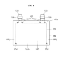
- FIG. 4 is a front view of an electrode assembly of a secondary battery according to another embodiment of the present invention.
- lower joining parts 254 are formed at intersections of the lower edge portion 144b and the left and right edge portions 144c and 144d, respectively. That is, the lower joining parts 254 are formed around lower corners of both sides of the first electrode plate (120 of FIG. 3 ) and/or the second electrode plate (130 of FIG. 3 ). In an exemplary embodiment, the lower joining parts 254 are formed to contact lower corners of both sides of the first electrode plate 120 and/or the second electrode plate 130.
- first electrode plate 120, the second electrode plate 130, and the separator 140 are stacked, and joining is performed on the upper joining part 152 and the lower joining part 254, left and right and downward movements of the first electrode plate 120 and/or the second electrode plate 130 can be prevented or substantially prevented by the lower joining part 254.
- FIG. 5 is a flowchart illustrating a method of manufacturing a secondary battery according to an embodiment of the present invention.
- an assembly for preventing or substantially preventing an electrode from moving may include a first (e.g., positive) and second (e.g., negative) electrode plate preparing step (S1), a separator preparing step (S2), a stacking step (S3), a joining step (S4), and a housing step (S5).
- a first (e.g., positive) and second (e.g., negative) electrode plate preparing step (S1) may be performed after the separator preparing step (S2).
- the first electrode plate 120 having the first electrode collector 121, the first electrode active material layer 122 and the first electrode tab 123, and the second electrode plate 130 having the second electrode collector 131, the second electrode active material layer 132 and the second electrode tab 133, are prepared.
- the separator 140 including the central portion 142, which is an overlapping area with the first electrode plate 120 and/or the second electrode plate 130, and the edge portion 144 extending outwardly from the central portion 142, is prepared.
- the separator 140 has the upper joining part 152 formed on the upper edge portion 144a of the edge portion 144, where the first electrode tab 123 and the second electrode tab 133 are positioned, and the lower joining part 154 formed on the lower edge portion 144b opposite to the upper edge portion 144a.
- the joining part 150 is yet to be formed in this step.
- the first electrode plate 120, the second electrode plate 130, and the separator 140 provided through the first and second electrode plate preparing step (S1) and the separator preparing step (S2) are stacked. That is to say, the separator 140 is interposed between the first electrode plate 120 and the second electrode plate 130 and aligned with respect to (e.g., aligned on centers of) the respective electrode plates for stacking.
- the upper joining part 152 and the lower joining part 154 are joined, respectively, such as by welding (e.g., ultrasonic welding), thermal fusing, or applying an adhesive.
- the joining may be ultrasonic welding, but the type of the joining is not limited to ultrasonic welding.
- the completed electrode assembly 110 resulting after the joining step (S4) is housed in the case 170, and an electrolyte is injected into the case 170, followed by hermetically sealing.
Landscapes
- Chemical & Material Sciences (AREA)
- Chemical Kinetics & Catalysis (AREA)
- Electrochemistry (AREA)
- General Chemical & Material Sciences (AREA)
- Engineering & Computer Science (AREA)
- Manufacturing & Machinery (AREA)
- Secondary Cells (AREA)
- Sealing Battery Cases Or Jackets (AREA)
- Cell Separators (AREA)
- Connection Of Batteries Or Terminals (AREA)
Abstract
Description
- The present invention relates to a secondary battery.
- Secondary batteries may be manufactured by spirally winding a positive electrode plate coated with a positive electrode active material, a separator, and a negative electrode plate coated with a negative electrode active material, or by housing an electrode assembly formed by sequentially stacking a positive electrode plate coated with a positive electrode active material, a separator, and a negative electrode plate coated with a negative electrode active material. In addition, secondary batteries may be classified into cylindrical types, prismatic types, or pouch types according to the external shape of a case accommodating the electrode assembly.
- In a typical stack-type electrode assembly formed by stacking a positive electrode plate, a negative electrode plate, and a separator, the stacked positive and negative electrode plates may move or deform due to external impact or vibration, resulting in misalignment.
- According to aspects of embodiments of the present invention, a secondary battery and a method of manufacturing the secondary battery can maintain a positive electrode plate and a negative electrode plate in proper alignment even when an external impact or vibration is applied to an electrode assembly.
- According to an embodiment of the present invention, a secondary battery includes: an electrode assembly including a first electrode plate including a first electrode collector and a first electrode tab protruding from a side of the first electrode collector; a second electrode plate including a second electrode collector and a second electrode tab protruding from a side of the second electrode collector; a first separator between the first electrode plate and the second electrode plate and including a central portion and an outer portion at a periphery of the central portion; and a second separator at a side of the first electrode plate or the second electrode plate opposite a side facing the first separator, the second separator including a central portion and an outer portion at a periphery of the central portion of the second separator, and the outer portion of the first separator and the outer portion of the second separator contact each other at least at a joining part; and a case containing the electrode assembly.
- The joining part may contact at least one of the first and second electrode plates. In one embodiment, the joining part fixes at least one of the first and second separators and the at least one of the first and second electrode plates together.
- The central portion of at least one of the first and second separators may contact at least one of the first and second electrode collectors.
- In one embodiment, the joining part includes at least one first joining part at a first side of the outer portion of at least one of the first and second separators and at least one second joining part at a second side of the outer portion of the at least one of the first and second separators opposite the first side. The first side may be adjacent one or both of the first and second electrode collectors. The at least one first joining part may include a pair of first joining parts at opposite sides along a widthwise direction of an electrode tab of the first and second electrode tabs.
- In one embodiment, the at least one first joining part includes a first pair of first joining parts at opposite sides along a widthwise direction, respectively, of the first electrode tab and contacting side portions of the first electrode tab and the side of the first electrode collector; and a second pair of first joining parts at opposite sides along a widthwise direction, respectively, of the second electrode tab and contacting side portions of the second electrode tab and the side of the second electrode collector.
- The at least one second joining part may be at a central portion of the second side of the outer portion. In one embodiment, the at least one second joining part includes a pair of second joining parts at opposite ends of the second side intersecting third and fourth sides, respectively, of the outer portion of the at least one of the first and second separators, the third and fourth sides being opposite each other and connecting the first and second sides of the outer portion of the at least one of the first and second separators.
- The joining part may include an ultrasonic welded part, a thermally fused part, or an adhesive. The first and second electrode collectors may be substantially plate-shaped and have substantially a same size. In one embodiment, at least one of the first and second separators is substantially plate-shaped, the central portion has a size corresponding to the size of the first and second electrode collectors, and the outer portion does not overlap the first and second electrode collectors. The case may be a pouch-type case. In one embodiment, a secondary battery further includes an insulation film between the case and at least one of the first and second electrode tabs.
- According to another embodiment of the present invention, a method of manufacturing a secondary battery includes: preparing a first electrode plate including a first electrode collector and a first electrode tab protruding from a side of the first electrode collector; preparing a second electrode plate including a second electrode collector and a second electrode tab protruding from a side of the second electrode collector; preparing a first separator including a central portion and an outer portion at a periphery of the central portion; preparing a second separator including a central portion and an outer portion at a periphery of the central portion of the second separator; stacking the first electrode plate, the first separator, the second electrode plate, and the second separator, the first separator being between the first and second electrode plates, and the second separator being at a side of the first electrode plate or the second electrode plate opposite a side facing the first separator; and preparing a joining part at which the outer portion of the first separator and the outer portion of the second separator contact each other.
- Preparing the joining part may include ultrasonic welding, thermal fusing, or applying an adhesive. Preparing the joining part may include contacting the joining part to at least one of the first and second electrode plates. In one embodiment, the joining part includes a plurality of joining parts, and preparing the joining part includes preparing at least one first joining part of the plurality of joining parts at a first side of the outer portion of at least one of the first and second separators, and preparing at least one second joining part of the plurality of joining parts at a second side of the outer portion of at least one of the first and second separators opposite the first side.
- According to another embodiment of the present invention, a secondary battery includes an electrode assembly including a positive electrode plate having a positive electrode tab, a negative electrode plate having a negative electrode tab, and a separator interposed between the positive electrode plate and the negative electrode plate and having a central portion contacting the positive electrode plate or the negative electrode plate, and an edge portion extending outwardly from the central portion, a case for housing the electrode assembly, an upper welding part formed on an upper edge portion, where the positive electrode tab and the negative electrode tab are positioned, and a lower welding part formed on a lower edge portion opposite to the upper edge portion.
- At least four of the upper welding part may be formed to contact side portions of each of the positive electrode tab and the negative electrode tab. The upper welding part may be formed to contact the upper sides of the positive electrode plate and the negative electrode plate.
- The lower welding part may be formed at the center of the lower edge portion. The lower welding part may be formed to contact lower corners of the positive electrode plate or the negative electrode plate, respectively.
- The upper welding part and the lower welding part may be subjected to ultrasonic welding.
- The case may be a pouch-type case.
- According to another embodiment of the present invention, a method of manufacturing a secondary battery includes an electrode plate preparing step of preparing a positive electrode plate having a positive electrode tab and a negative electrode plate having a negative electrode tab; a separator preparing step of preparing a separator having a central portion contacting the positive electrode plate or the negative electrode plate, and an edge portion extending outwardly from the central portion, and including an upper welding part formed on an upper edge portion, where the positive electrode tab and the negative electrode tab are positioned, and a lower welding part formed on a lower edge portion opposite to the upper edge portion; a stacking step of stacking the positive electrode plate, the negative electrode plate, and the separator; a welding step of welding the upper welding part and the lower welding part, respectively; and a housing step of housing a completed electrode assembly resulting after the welding step.
- According to embodiments of an electrode assembly, a secondary battery including the same, and a manufacturing method of the present invention, since a joining part is provided in a separator, the electrode assembly can maintain alignment between a first electrode plate and a second electrode plate even during an external impact or vibration, and, as a result, the cell stability of the battery can be enhanced while improving the life characteristic of the battery.
- The above and other features and advantages will become more apparent to those of ordinary skill in the art by describing in detail some exemplary embodiments of the present invention with reference to the attached drawings.
-
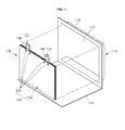
FIG. 1 is an exploded perspective view of a secondary battery according to an embodiment of the present invention; -
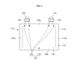
FIG. 2 is a front view of an electrode assembly of the secondary battery ofFIG. 1 according to an embodiment of the present invention; -
FIG. 3 is an exploded perspective view of the electrode assembly ofFIG. 2 ; -
FIG. 4 is a front view of an electrode assembly of a secondary battery according to another embodiment of the present invention; and -
FIG. 5 is a flowchart illustrating a method of manufacturing a secondary battery according to an embodiment of the present invention. - An electrode assembly according to an embodiment of the present invention and a secondary battery including the same will first be described.
- Referring to
FIGS. 1 through 3 , asecondary battery 100 includes anelectrode assembly 110 and acase 170. - The
electrode assembly 110 includes a first electrode plate 120 (e.g., a positive electrode plate), a second electrode plate 130 (e.g., a negative electrode plate), aseparator 140, and a joiningpart 150. Theelectrode assembly 110, in one embodiment, further includes aninsulation film 160. - The
first electrode plate 120, in one embodiment, is formed by coating a first electrode active material layer 122 (e.g., a positive electrode active material layer) on both surfaces of a substantially plate-shaped first electrode collector 121 (e.g., a positive electrode collector). Thefirst electrode collector 121 may be made of aluminum foil having excellent conductivity. In one embodiment, thefirst electrode plate 120 includes a first electrode tab 123 (e.g., a positive electrode tab) in the form of a protrusion on a side portion of thefirst electrode collector 121, and the first electrodeactive material layer 122 is coated on parts of thefirst electrode collector 121 excluding thefirst electrode tab 123 and predetermined portions under thefirst electrode tab 123. The first electrodeactive material layer 122 may be made of a laminate compound including lithium, a binder for increasing a binding force, and a conductive member for increasing conductivity. - The
second electrode plate 130, in one embodiment, is formed by coating a second electrode active material layer 132 (e.g., a negative electrode active material layer) on both surfaces of a second electrode collector 131 (e.g., a negative electrode collector) that is substantially plate-shaped to correspond to thefirst electrode collector 121. Thesecond electrode collector 131 may be made of copper (Cu) foil having excellent conductivity. In one embodiment, thesecond electrode plate 130 includes a second electrode tab 133 (e.g., a negative electrode tab) in the form of a protrusion on a side portion of thesecond electrode collector 131, and the second electrodeactive material layer 132 is coated on parts of thesecond electrode collector 131 excluding thesecond electrode tab 133 and predetermined portions under thesecond electrode tab 133. The second electrodeactive material layer 132 may be made of a hard carbon material including carbon or graphite, and a binder for increasing a binding force. In addition, thesecond electrode tab 133 is spaced apart from thefirst electrode tab 123. - The
separator 140 is substantially plate-shaped to correspond to thefirst electrode plate 120 and/or thesecond electrode plate 130 and is generally sized to be slightly larger than thefirst electrode plate 120 and/or thesecond electrode plate 130. Theseparator 140 may be a porous film made of polyethylene (PE), polypropylene (PP), or a composite film thereof. - The
separator 140, which is interposed between thefirst electrode plate 120 and thesecond electrode plate 130, electrically insulates thefirst electrode plate 120 and thesecond electrode plate 130 and passes charges of thefirst electrode plate 120 and thesecond electrode plate 130. - The
separator 140 is positioned between thefirst electrode plate 120 and thesecond electrode plate 130, and includes acentral portion 142 contacting thefirst electrode plate 120 and/or thesecond electrode plate 130, and anedge portion 144 extending outwardly from thecentral portion 142 while not overlapping thefirst electrode plate 120 or thesecond electrode plate 130. Further, the separator 140 (e.g., a first separator) may be adjacent to another separator 140 (e.g., a second separator) that is arranged at a side of thefirst electrode plate 120 or thesecond electrode plate 130 opposite a side facing the separator 140 (i.e. the first separator). - The
edge portion 144, in one embodiment, includes anupper edge portion 144a formed on an upper side of thecentral portion 142, alower edge portion 144b formed on a lower side of thecentral portion 142, and left andright edge portions central portion 142. - The joining
part 150, in one embodiment, includes an upper joiningpart 152 and a lower joiningpart 154. - The upper joining
part 152, in one embodiment, is formed on theupper edge portion 144a where thefirst electrode tab 123 and thesecond electrode tab 133 are arranged. - In one embodiment, the upper joining
part 152 is formed at locations corresponding to side portions (e.g., opposite side portions) of thefirst electrode tab 123 and side portions (e.g., opposite side portions) of thesecond electrode tab 133, so that at least four upper joining parts are formed. - In addition, the upper joining
part 152, in one embodiment, is formed to contact upper sides of thefirst electrode plate 120 and/or thesecond electrode plate 130 while contacting side portions (e.g., opposite side portions) of each of thefirst electrode tab 123 and thesecond electrode tab 133. - The lower joining
part 154, in one embodiment, is formed at or near the center of thelower edge portion 144b opposite to the upper joiningpart 152. - In addition, the lower joining
part 154, in one embodiment, is formed to contact lower sides of thefirst electrode plate 120 and/or thesecond electrode plate 130. - The upper joining
part 152 and the lower joiningpart 154, in one embodiment, are subjected to ultrasonic welding, respectively, thereby tightly fixing the stacked structure of thefirst electrode plate 120, thesecond electrode plate 130, and theseparator 140. However, the upper joiningpart 152 and the lower joiningpart 154 are not limited to an ultrasonic welded part in embodiments of the present invention, but may be formed by any other suitable welded part, a thermally fused part, or an adhesive. Further, in one embodiment, the separator 140 (i.e. the first separator) and the adjacent separator 140 (i.e. the second separator) contact each other at the joiningpart 150 so that the joiningpart 150 fixes the stacked structure of thefirst electrode plate 120, thesecond electrode plate 130, and theadjacent separators 140. - Therefore, since the opposite sides of each of the
first electrode tab 123 and thesecond electrode tab 133 are fixed by the upper joiningpart 152, thefirst electrode plate 120 and/or thesecond electrode plate 130 can be prevented or substantially prevented from moving to the sides (e.g., left and right), such as due to an external impact or vibration. In addition, since the upper sides of thefirst electrode plate 120 and/or thesecond electrode plate 130 are fixed by the upper joiningpart 152, thefirst electrode plate 120 and/or thesecond electrode plate 130 can be prevented or substantially prevented from moving upward. - Further, because the lower side of the
first electrode plate 120 and/or thesecond electrode plate 130 is fixed by the lower joiningpart 154, thefirst electrode plate 120 and/or thesecond electrode plate 130 can be prevented or substantially prevented from moving downward, such as due to an external impact or vibration. - The lower joining
part 154 may be positioned at any suitable location of thelower edge portion 144b as long as it is positioned within an intersecting region of the left andright edge portions first electrode plate 120 and/or thesecond electrode plate 130 in a stable manner, the lower joiningpart 154 is positioned substantially at a center of the left andright edge portions - The
insulation film 160 is configured to enclose the case 170 (e.g., a pouch-type case) described further below and thefirst electrode tab 123 and thesecond electrode tab 133 stacked for electrical insulation. - The
case 170 will be described with regard to a pouch-type case according to one example embodiment of the present invention. However, embodiments of the present invention are not limited to a pouch-type case, and thecase 170 may be formed of a cylindrical or prismatic can or case. - With reference to
FIG. 1 , thecase 170, in one embodiment, includes abody 172 having an inner space in which theelectrode assembly 110 is placed and having an electrolyte filled therein, and acover 174 integrally extending from one end of thebody 172. In one embodiment, aflange 176 is formed at an edge of the body and is joined with thecover 174 to hermetically seal thebody 172. - As described above, in the
electrode assembly 110 according to an embodiment of the present invention and thesecondary battery 100 including the same, due to the joiningpart 150 in theseparator 140, when an external impact or vibration is applied to theelectrode assembly 110, alignment between thefirst electrode plate 120 and thesecond electrode plate 130 can be maintained and the stability of the battery cell can be enhanced while improving the life characteristic of the battery. - Next, an electrode assembly according to another embodiment of the present invention and a secondary battery including the same will be described.
- Since functional components of the illustrated embodiment are substantially the same as those of the
electrode assembly 110 according to the previously described embodiment, with the exception of a lower joining part, descriptions of the same components will be omitted. -
FIG. 4 is a front view of an electrode assembly of a secondary battery according to another embodiment of the present invention. - Referring to
FIG. 4 , in one embodiment, lower joiningparts 254 are formed at intersections of thelower edge portion 144b and the left andright edge portions parts 254 are formed around lower corners of both sides of the first electrode plate (120 ofFIG. 3 ) and/or the second electrode plate (130 ofFIG. 3 ). In an exemplary embodiment, the lower joiningparts 254 are formed to contact lower corners of both sides of thefirst electrode plate 120 and/or thesecond electrode plate 130. - When the
first electrode plate 120, thesecond electrode plate 130, and theseparator 140 are stacked, and joining is performed on the upper joiningpart 152 and the lower joiningpart 254, left and right and downward movements of thefirst electrode plate 120 and/or thesecond electrode plate 130 can be prevented or substantially prevented by the lower joiningpart 254. - A method of manufacturing a secondary battery according to an embodiment of the present invention will now be described.
-
FIG. 5 is a flowchart illustrating a method of manufacturing a secondary battery according to an embodiment of the present invention. - Referring to
FIGS. 1 through 5 , an assembly for preventing or substantially preventing an electrode from moving may include a first (e.g., positive) and second (e.g., negative) electrode plate preparing step (S1), a separator preparing step (S2), a stacking step (S3), a joining step (S4), and a housing step (S5). Of course, the above-described steps of the method of manufacturing a secondary battery according to the present invention is not limited to carrying out the above-described steps, or tasks, in the above-listed order or as shown inFIG. 5 . For example, the first (e.g., positive) and second (e.g., negative) electrode plate preparing step (S1) may be performed after the separator preparing step (S2). - In the first and second electrode plate preparing step (S1), as described above with regard to the
first electrode plate 120 and thesecond electrode plate 130, thefirst electrode plate 120 having thefirst electrode collector 121, the first electrodeactive material layer 122 and thefirst electrode tab 123, and thesecond electrode plate 130 having thesecond electrode collector 131, the second electrodeactive material layer 132 and thesecond electrode tab 133, are prepared. - In the separator preparing step (S2), the
separator 140 including thecentral portion 142, which is an overlapping area with thefirst electrode plate 120 and/or thesecond electrode plate 130, and theedge portion 144 extending outwardly from thecentral portion 142, is prepared. Theseparator 140 has the upper joiningpart 152 formed on theupper edge portion 144a of theedge portion 144, where thefirst electrode tab 123 and thesecond electrode tab 133 are positioned, and the lower joiningpart 154 formed on thelower edge portion 144b opposite to theupper edge portion 144a. However, the joiningpart 150 is yet to be formed in this step. - In the stacking step (S3), the
first electrode plate 120, thesecond electrode plate 130, and theseparator 140 provided through the first and second electrode plate preparing step (S1) and the separator preparing step (S2) are stacked. That is to say, theseparator 140 is interposed between thefirst electrode plate 120 and thesecond electrode plate 130 and aligned with respect to (e.g., aligned on centers of) the respective electrode plates for stacking. - In the joining step (S4), the upper joining
part 152 and the lower joiningpart 154 are joined, respectively, such as by welding (e.g., ultrasonic welding), thermal fusing, or applying an adhesive. - The joining may be ultrasonic welding, but the type of the joining is not limited to ultrasonic welding.
- In the housing step (S5), according to one embodiment, the completed
electrode assembly 110 resulting after the joining step (S4) is housed in thecase 170, and an electrolyte is injected into thecase 170, followed by hermetically sealing. - Some exemplary embodiments have been disclosed herein, and although specific terms are employed, they are used and are to be interpreted in a generic and descriptive sense only and not for purpose of limitation. Accordingly, it will be understood by those of ordinary skill in the art that various changes in form and details may be made without departing from the scope of the present invention as set forth in the following claims.
Claims (15)
- A secondary battery comprising:an electrode assembly (110) and a case (170) housing the electrode assembly, the electrode assembly comprising:a first electrode plate (120) comprising a first electrode collector (121) and a first electrode tab (123) protruding from a side of the first electrode collector;a second electrode plate (130) comprising a second electrode collector (131) and a second electrode tab (133) protruding from a side of the second electrode collector;a first separator (140) between the first and second electrode plates (120, 130); anda second separator (140) at a side of the first electrode plate or the second electrode plate opposite a side facing the first separator,wherein an outer portion of the first separator and an outer portion of the second separator contact each other at a joining part (150).
- The secondary battery of claim 1, wherein the joining part contacts at least one of the first and second electrode plates.
- The secondary battery of claim 2, wherein the joining part fixes at least one of the first and second separators and the at least one of the first and second electrode plates together.
- The secondary battery of any one of the preceding claims, wherein a central portion of at least one of the first and second separators contacts at least one of the first and second electrode collectors.
- The secondary battery of any one of the preceding claims, wherein the joining part comprises at least one first joining part (152) at a first side of the outer portion of at least one of the first and second separators and at least one second joining part (154, 254) at a second side of the outer portion of the at least one of the first and second separators opposite the first side.
- The secondary battery of claim 5, wherein the first side is adjacent to one or both of the first and second electrode collectors.
- The secondary battery of claim 5 or 6, wherein the at least one first joining part comprises a pair of first joining parts (152) at opposite sides of one of the first and second electrode tabs.
- The secondary battery of claim 5, 6 or 7, wherein the at least one first joining part comprises:a first pair of first joining parts (152) at opposite sides of the first electrode tab (123) and contacting side portions of the first electrode tab and the side of the first electrode collector (121); anda second pair of first joining parts (152) at opposite sides of the second electrode tab (133) and contacting side portions of the second electrode tab and the side of the second electrode collector (131).
- The secondary battery of any one of claims 5 to 8, wherein the at least one second joining part (154) is at a central portion of the second side of the outer portion.
- The secondary battery of any one of claims 5 to 8, wherein the at least one second joining part comprises a pair of second joining parts (254) at opposite ends of the second side of the outer portion of the at least one of the first and second separators.
- The secondary battery of claim 9 or 10, wherein the or each second joining part (154, 254) is in contact with a side of the first and/or second electrode plate (120, 130).
- The secondary battery of any one of the preceding claims, wherein the joining part comprises an ultrasonic welded part, a thermally fused part, or an adhesive.
- The secondary battery of any one of the preceding claims, wherein the first and second electrode collectors are substantially plate-shaped and have substantially the same size.
- The secondary battery of claim 13, wherein at least one of the first and second separators is substantially plate-shaped, the size of the central portion of the separator corresponding to the size of the first and second electrode collectors, and the outer portion of the separator not overlapping the first and second electrode collectors.
- The secondary battery of any one of the preceding claims, wherein the case is a pouch-type case.
Applications Claiming Priority (2)
| Application Number | Priority Date | Filing Date | Title |
|---|---|---|---|
| US38239210P | 2010-09-13 | 2010-09-13 | |
| US13/051,981 US9048487B2 (en) | 2010-09-13 | 2011-03-18 | Secondary battery and manufacturing method thereof |
Publications (1)
| Publication Number | Publication Date |
|---|---|
| EP2429012A1 true EP2429012A1 (en) | 2012-03-14 |
Family
ID=44720623
Family Applications (1)
| Application Number | Title | Priority Date | Filing Date |
|---|---|---|---|
| EP11180796A Withdrawn EP2429012A1 (en) | 2010-09-13 | 2011-09-09 | Secondary battery |
Country Status (5)
| Country | Link |
|---|---|
| US (1) | US9048487B2 (en) |
| EP (1) | EP2429012A1 (en) |
| JP (1) | JP5560243B2 (en) |
| KR (1) | KR101318598B1 (en) |
| CN (1) | CN102412379B (en) |
Families Citing this family (8)
| Publication number | Priority date | Publication date | Assignee | Title |
|---|---|---|---|---|
| US9793571B2 (en) | 2013-10-03 | 2017-10-17 | Nissan Motor Co., Ltd. | Apparatus for bonding separators in electrical devices |
| EP3161899A4 (en) | 2014-06-30 | 2017-12-27 | Black & Decker Inc. | Battery pack for a cordless power tools |
| WO2016056256A1 (en) | 2014-10-10 | 2016-04-14 | 住友化学株式会社 | Manufacturing method for separator wound body for battery, separator wound body for battery, and apparatus for manufacturing separator wound body for battery |
| CN108807829B (en) * | 2014-11-10 | 2020-09-15 | 东莞新能源科技有限公司 | Cells and Electrochemical Devices |
| JP6693840B2 (en) * | 2016-08-31 | 2020-05-13 | 京セラ株式会社 | Flow battery |
| CN109213339B (en) * | 2017-07-03 | 2022-01-25 | 群光电子股份有限公司 | End face contact type charging module and touch control pen thereof |
| KR20240167259A (en) * | 2023-05-19 | 2024-11-26 | 주식회사 엘지에너지솔루션 | Battery module and battery cell center determination method |
| KR20250135449A (en) * | 2024-03-06 | 2025-09-15 | 주식회사 엘지에너지솔루션 | Unit cell and manufacturing method thereof |
Citations (7)
| Publication number | Priority date | Publication date | Assignee | Title |
|---|---|---|---|---|
| EP0136886A2 (en) * | 1983-09-30 | 1985-04-10 | Union Carbide Corporation | Electrode assembly |
| EP1708214A2 (en) * | 2005-03-30 | 2006-10-04 | TDK Corporation | Electrochemical device |
| US20070099071A1 (en) * | 2005-11-02 | 2007-05-03 | Cardiac Pacemakers, Inc. | System and method for sealing battery separator |
| DE102007025766A1 (en) * | 2007-05-23 | 2008-11-27 | Varta Microbattery Gmbh | Galvanic element such as commercial lithium-ion cells and lithium-polymer cells, has single cell with combination of planar separators and electrodes |
| JP2009218540A (en) * | 2008-03-12 | 2009-09-24 | Office Emd Kk | Electric storage device |
| US20090297929A1 (en) * | 2008-05-29 | 2009-12-03 | Sony Corporation | Winding electrode body, nonaqueous electrolyte secondary battery, and method for manufacturing winding electrode body |
| WO2010089152A1 (en) * | 2009-02-09 | 2010-08-12 | Varta Microbattery Gmbh | Button cells and method for producing same |
Family Cites Families (11)
| Publication number | Priority date | Publication date | Assignee | Title |
|---|---|---|---|---|
| JP3605851B2 (en) | 1994-05-31 | 2004-12-22 | ソニー株式会社 | Rechargeable battery |
| JPH0896829A (en) | 1994-09-22 | 1996-04-12 | Sony Corp | Secondary battery |
| KR100337707B1 (en) * | 2000-09-25 | 2002-05-22 | 정근창 | Pocketed electrode plate for use in lithium ion secondary battery, its manufacturing method and lithium ion secondary battery using the same |
| JP2002208442A (en) | 2001-01-11 | 2002-07-26 | Tdk Corp | Electrochemical device |
| JP4135474B2 (en) | 2002-11-07 | 2008-08-20 | 日産自動車株式会社 | Laminated secondary battery, assembled battery module comprising a plurality of laminated secondary batteries, assembled battery comprising a plurality of assembled battery modules, and an electric vehicle equipped with any of these batteries |
| JP5032737B2 (en) | 2004-06-14 | 2012-09-26 | パナソニック株式会社 | Electrochemical element |
| EP2002495B1 (en) | 2006-04-03 | 2015-09-09 | LG Chem, Ltd. | Lithium secondary battery improved safety and capacity |
| JP4753369B2 (en) | 2006-04-28 | 2011-08-24 | Necトーキン株式会社 | Stacked electrochemical device |
| KR100891383B1 (en) * | 2007-05-21 | 2009-04-02 | 삼성에스디아이 주식회사 | Pouch Type Secondary Battery |
| JP5315789B2 (en) | 2008-05-19 | 2013-10-16 | 日産自動車株式会社 | Manufacturing method of stacked battery |
| JP4659861B2 (en) | 2008-07-09 | 2011-03-30 | シャープ株式会社 | Flat secondary battery and manufacturing method thereof |
-
2011
- 2011-03-18 US US13/051,981 patent/US9048487B2/en not_active Expired - Fee Related
- 2011-07-05 KR KR1020110066580A patent/KR101318598B1/en not_active Expired - Fee Related
- 2011-08-01 JP JP2011168128A patent/JP5560243B2/en not_active Expired - Fee Related
- 2011-09-09 EP EP11180796A patent/EP2429012A1/en not_active Withdrawn
- 2011-09-09 CN CN201110281451.3A patent/CN102412379B/en not_active Expired - Fee Related
Patent Citations (7)
| Publication number | Priority date | Publication date | Assignee | Title |
|---|---|---|---|---|
| EP0136886A2 (en) * | 1983-09-30 | 1985-04-10 | Union Carbide Corporation | Electrode assembly |
| EP1708214A2 (en) * | 2005-03-30 | 2006-10-04 | TDK Corporation | Electrochemical device |
| US20070099071A1 (en) * | 2005-11-02 | 2007-05-03 | Cardiac Pacemakers, Inc. | System and method for sealing battery separator |
| DE102007025766A1 (en) * | 2007-05-23 | 2008-11-27 | Varta Microbattery Gmbh | Galvanic element such as commercial lithium-ion cells and lithium-polymer cells, has single cell with combination of planar separators and electrodes |
| JP2009218540A (en) * | 2008-03-12 | 2009-09-24 | Office Emd Kk | Electric storage device |
| US20090297929A1 (en) * | 2008-05-29 | 2009-12-03 | Sony Corporation | Winding electrode body, nonaqueous electrolyte secondary battery, and method for manufacturing winding electrode body |
| WO2010089152A1 (en) * | 2009-02-09 | 2010-08-12 | Varta Microbattery Gmbh | Button cells and method for producing same |
Also Published As
| Publication number | Publication date |
|---|---|
| JP2012059696A (en) | 2012-03-22 |
| US9048487B2 (en) | 2015-06-02 |
| KR101318598B1 (en) | 2013-10-15 |
| US20120064385A1 (en) | 2012-03-15 |
| CN102412379A (en) | 2012-04-11 |
| CN102412379B (en) | 2014-12-24 |
| JP5560243B2 (en) | 2014-07-23 |
| KR20120028211A (en) | 2012-03-22 |
Similar Documents
| Publication | Publication Date | Title |
|---|---|---|
| KR102700153B1 (en) | Electrode assembly | |
| EP2299511B1 (en) | Rechargeable battery and battery module | |
| JP6595162B2 (en) | Secondary battery manufacturing method | |
| KR101191663B1 (en) | Rechargeable battery | |
| KR101808923B1 (en) | Manufacturing method for secondary battery and secondary battery | |
| KR101863703B1 (en) | Pouch-type secondary battery and method for manufacturing the same | |
| KR101106428B1 (en) | Secondary battery | |
| EP2429012A1 (en) | Secondary battery | |
| EP2610945B1 (en) | Stacked cell | |
| KR102689862B1 (en) | Secondary battery | |
| KR20130139472A (en) | Battery assembly having single electrode terminal connecting part | |
| JP6045987B2 (en) | Prismatic secondary battery | |
| US20110104572A1 (en) | Electrode assembly for secondary battery and method of making the electrode assembly | |
| US20110076544A1 (en) | Stack type battery | |
| JP7825664B2 (en) | battery | |
| KR101821488B1 (en) | Battery | |
| KR20220002540A (en) | cell battery | |
| JP2019061892A (en) | Power storage element | |
| KR20180122073A (en) | Flexible electrode assembly having strengthening structure using expanded metal on outermost electrode | |
| WO2024142444A1 (en) | Rectangular secondary battery | |
| KR20170022372A (en) | Secondary Battery And Fabricating Method Thereof | |
| JP6731182B2 (en) | Electric storage element and method for manufacturing electric storage element | |
| KR102892116B1 (en) | Electrode assembly and manufacturing method thereof, secondary battery comprising the same | |
| EP4481902A1 (en) | Electricity storage device and method of manufacturing electricity storage device | |
| US20250316798A1 (en) | Secondary battery |
Legal Events
| Date | Code | Title | Description |
|---|---|---|---|
| AK | Designated contracting states |
Kind code of ref document: A1 Designated state(s): AL AT BE BG CH CY CZ DE DK EE ES FI FR GB GR HR HU IE IS IT LI LT LU LV MC MK MT NL NO PL PT RO RS SE SI SK SM TR |
|
| AX | Request for extension of the european patent |
Extension state: BA ME |
|
| PUAI | Public reference made under article 153(3) epc to a published international application that has entered the european phase |
Free format text: ORIGINAL CODE: 0009012 |
|
| 17P | Request for examination filed |
Effective date: 20120321 |
|
| 17Q | First examination report despatched |
Effective date: 20130528 |
|
| GRAP | Despatch of communication of intention to grant a patent |
Free format text: ORIGINAL CODE: EPIDOSNIGR1 |
|
| INTG | Intention to grant announced |
Effective date: 20160404 |
|
| STAA | Information on the status of an ep patent application or granted ep patent |
Free format text: STATUS: THE APPLICATION IS DEEMED TO BE WITHDRAWN |
|
| 18D | Application deemed to be withdrawn |
Effective date: 20160817 |