EP2428668A2 - Fuel injection control apparatus - Google Patents
Fuel injection control apparatus Download PDFInfo
- Publication number
- EP2428668A2 EP2428668A2 EP11179456A EP11179456A EP2428668A2 EP 2428668 A2 EP2428668 A2 EP 2428668A2 EP 11179456 A EP11179456 A EP 11179456A EP 11179456 A EP11179456 A EP 11179456A EP 2428668 A2 EP2428668 A2 EP 2428668A2
- Authority
- EP
- European Patent Office
- Prior art keywords
- fuel injection
- cylinder
- calculation
- rotation speed
- control apparatus
- Prior art date
- Legal status (The legal status is an assumption and is not a legal conclusion. Google has not performed a legal analysis and makes no representation as to the accuracy of the status listed.)
- Granted
Links
Images

Classifications
-
- F—MECHANICAL ENGINEERING; LIGHTING; HEATING; WEAPONS; BLASTING
- F02—COMBUSTION ENGINES; HOT-GAS OR COMBUSTION-PRODUCT ENGINE PLANTS
- F02D—CONTROLLING COMBUSTION ENGINES
- F02D41/00—Electrical control of supply of combustible mixture or its constituents
- F02D41/008—Controlling each cylinder individually
-
- F—MECHANICAL ENGINEERING; LIGHTING; HEATING; WEAPONS; BLASTING
- F02—COMBUSTION ENGINES; HOT-GAS OR COMBUSTION-PRODUCT ENGINE PLANTS
- F02D—CONTROLLING COMBUSTION ENGINES
- F02D41/00—Electrical control of supply of combustible mixture or its constituents
- F02D41/009—Electrical control of supply of combustible mixture or its constituents using means for generating position or synchronisation signals
-
- F—MECHANICAL ENGINEERING; LIGHTING; HEATING; WEAPONS; BLASTING
- F02—COMBUSTION ENGINES; HOT-GAS OR COMBUSTION-PRODUCT ENGINE PLANTS
- F02D—CONTROLLING COMBUSTION ENGINES
- F02D41/00—Electrical control of supply of combustible mixture or its constituents
- F02D41/02—Circuit arrangements for generating control signals
- F02D41/04—Introducing corrections for particular operating conditions
- F02D41/10—Introducing corrections for particular operating conditions for acceleration
- F02D41/107—Introducing corrections for particular operating conditions for acceleration and deceleration
-
- F—MECHANICAL ENGINEERING; LIGHTING; HEATING; WEAPONS; BLASTING
- F02—COMBUSTION ENGINES; HOT-GAS OR COMBUSTION-PRODUCT ENGINE PLANTS
- F02D—CONTROLLING COMBUSTION ENGINES
- F02D41/00—Electrical control of supply of combustible mixture or its constituents
- F02D41/24—Electrical control of supply of combustible mixture or its constituents characterised by the use of digital means
- F02D41/2406—Electrical control of supply of combustible mixture or its constituents characterised by the use of digital means using essentially read only memories
- F02D41/2409—Addressing techniques specially adapted therefor
-
- F—MECHANICAL ENGINEERING; LIGHTING; HEATING; WEAPONS; BLASTING
- F02—COMBUSTION ENGINES; HOT-GAS OR COMBUSTION-PRODUCT ENGINE PLANTS
- F02B—INTERNAL-COMBUSTION PISTON ENGINES; COMBUSTION ENGINES IN GENERAL
- F02B75/00—Other engines
- F02B75/16—Engines characterised by number of cylinders, e.g. single-cylinder engines
- F02B75/18—Multi-cylinder engines
- F02B2075/1804—Number of cylinders
- F02B2075/1832—Number of cylinders eight
-
- F—MECHANICAL ENGINEERING; LIGHTING; HEATING; WEAPONS; BLASTING
- F02—COMBUSTION ENGINES; HOT-GAS OR COMBUSTION-PRODUCT ENGINE PLANTS
- F02D—CONTROLLING COMBUSTION ENGINES
- F02D2250/00—Engine control related to specific problems or objectives
- F02D2250/12—Timing of calculation, i.e. specific timing aspects when calculation or updating of engine parameter is performed
-
- F—MECHANICAL ENGINEERING; LIGHTING; HEATING; WEAPONS; BLASTING
- F02—COMBUSTION ENGINES; HOT-GAS OR COMBUSTION-PRODUCT ENGINE PLANTS
- F02D—CONTROLLING COMBUSTION ENGINES
- F02D41/00—Electrical control of supply of combustible mixture or its constituents
- F02D41/24—Electrical control of supply of combustible mixture or its constituents characterised by the use of digital means
- F02D41/2406—Electrical control of supply of combustible mixture or its constituents characterised by the use of digital means using essentially read only memories
- F02D41/2425—Particular ways of programming the data
- F02D41/2429—Methods of calibrating or learning
- F02D41/2432—Methods of calibration
-
- F—MECHANICAL ENGINEERING; LIGHTING; HEATING; WEAPONS; BLASTING
- F02—COMBUSTION ENGINES; HOT-GAS OR COMBUSTION-PRODUCT ENGINE PLANTS
- F02D—CONTROLLING COMBUSTION ENGINES
- F02D41/00—Electrical control of supply of combustible mixture or its constituents
- F02D41/30—Controlling fuel injection
- F02D41/38—Controlling fuel injection of the high pressure type
- F02D41/40—Controlling fuel injection of the high pressure type with means for controlling injection timing or duration
- F02D41/402—Multiple injections
-
- F—MECHANICAL ENGINEERING; LIGHTING; HEATING; WEAPONS; BLASTING
- F02—COMBUSTION ENGINES; HOT-GAS OR COMBUSTION-PRODUCT ENGINE PLANTS
- F02P—IGNITION, OTHER THAN COMPRESSION IGNITION, FOR INTERNAL-COMBUSTION ENGINES; TESTING OF IGNITION TIMING IN COMPRESSION-IGNITION ENGINES
- F02P7/00—Arrangements of distributors, circuit-makers or -breakers, e.g. of distributor and circuit-breaker combinations or pick-up devices
- F02P7/06—Arrangements of distributors, circuit-makers or -breakers, e.g. of distributor and circuit-breaker combinations or pick-up devices of circuit-makers or -breakers, or pick-up devices adapted to sense particular points of the timing cycle
- F02P7/067—Electromagnetic pick-up devices, e.g. providing induced current in a coil
Definitions
- the present invention relates to a fuel injection control apparatus for a diesel engine.
- a common rail type diesel engine In recent years, common rail type diesel engines have gained prominence among diesel engines. In a common rail type diesel engine, split injection and so on can be performed easily by having a fuel injection control apparatus control energization time (valve opening time) of a fuel injection valve (injector), and therefore injection can be performed with a high degree of freedom.
- the fuel injection control apparatus typically starts to calculate fuel injection amounts for respective cylinders on the basis of a predetermined crank angle. To ensure that fuel is injected into the respective cylinders reliably, calculation of the fuel injection amounts must be completed at a timing before the start of fuel injection when injection is not impaired, or in other words before a calculation completion limit angle.
- an interval between the calculation start timing of the fuel injection amount and an injection energization start timing of the fuel injection valve is preferably as short as possible.
- the reason for this is that as time elapses, variations occur in information relating to operating conditions (engine rotation speed, load, pressure in a common rail, and so on) used in the calculation, and therefore control can be executed with a higher degree of precision as the aforementioned interval decreases.
- the engine rotation speed of an automobile in particular varies within a wide range from a low rotation speed to a high rotation speed.
- Japanese Patent Application Publication No. 2004-150321 proposes a technique of setting two predetermined crank angles corresponding to the calculation start timing following the start of injection into a certain cylinder and before the start of injection into the next cylinder to be subjected to fuel injection, and modifying the calculation start timing on the basis of the rotation speed.
- a diesel engine described in Japanese Patent Application Publication No. 2004-150321 is a four-cylinder engine, but as the number of cylinders in a diesel engine increases, the crank angle that can be used to calculate the fuel injection amount narrows, leading to a reduction in the actual amount of time that can be used for the calculation. For example, when the crank angle of a single cycle is divided by the number of cylinders, 180° is obtained in a four-cylinder diesel engine but only 90° is obtained in an eight-cylinder diesel engine. Therefore, when an attempt is made to perform similar control in a diesel engine having a large number of cylinders, i.e.
- calculation of the fuel injection amount is not completed by the calculation completion limit angle on the high rotation speed side of the engine, even if the calculation start timing is advanced as far as possible.
- calculation of the fuel injection amount is not completed in time, fuel injection may be missed or performed without making use of the calculation result.
- Measures may easily be taken to simplify the content of the calculation processing or to employ a high-performance ECU in the fuel injection amount control apparatus. In this case, however, new problems such as deterioration of the precision of the fuel injection amount control and cost increases arise.
- the present invention has been designed to solve these problems, and an object thereof is to provide a fuel injection control apparatus that can inject fuel into respective cylinders without missing any of the cylinders and without causing the problems described above.
- the present invention provides a fuel injection control apparatus for a diesel engine having a plurality of cylinders, the fuel injection control apparatus comprising: a calculation unit that calculates a fuel injection amount for each cylinder; and a storage unit that has a storage area corresponding to each cylinder and stores in a corresponding storage area a calculation result generated by the calculation unit, the fuel injection control apparatus being characterized in that, when the rotation speed of the diesel engine is equal to or lower than a preset reference rotation speed, the calculation result is stored in a corresponding storage area as a fuel injection amount for each of two cylinders, namely a first cylinder, which is a cylinder first subjected to fuel injection following the start of the calculation, and a following cylinder, which is a cylinder subjected to fuel injection following the first cylinder, and when the rotation speed of the diesel engine is higher than the reference rotation speed, the calculation result is stored in the corresponding storage area as at least the fuel injection amount of the following cylinder.
- Fig. 1 shows the constitution of a diesel engine including a fuel injection control apparatus according to an embodiment of the present invention.
- a diesel engine 1 is a V type eight-cylinder common rail diesel engine.
- Each cylinder 2 (only one cylinder is shown in Fig. 1 ) is provided with an injector 3 for injecting fuel into the cylinder.
- Each injector 3 is provided with a solenoid valve 4 for ON/OFF control of the fuel injection.
- the injector 3 is connected to a common rail 5 by a high pressure fuel pipe 14. Fuel is accumulated in the common rail 5 in a high pressure state such that when the solenoid valve 4 is opened, the fuel is fed through the fuel pipe 14 by an internal pressure of the common rail 5 and injected from the injector 3. The fuel is supplied to the common rail 5 from a fuel tank 7 by a pump 6 such that the internal pressure of the common rail 5 is maintained at a predetermined pressure.
- the diesel engine 1 is further provided with an ECU 8 for controlling an operation of the diesel engine 1.
- the ECU 8 is provided with a calculation unit 15 for calculating a fuel injection amount on the basis of operating conditions of the diesel engine 1, and a storage unit 16 for storing information relating to fuel injection into the respective cylinders 2.
- the storage unit 16 includes eight storage areas 16a to 16h corresponding to the respective cylinders 2, and the storage areas 16a to 16h respectively store calculation results generated by the calculation unit 15 in relation to the fuel injection amounts for the respective cylinders 2. Further, correction information corresponding to a corresponding cylinder 2 is stored separately in each storage area 16a to 16h.
- the correction information is based on temporal deterioration of the injector 3, a degree of blockage of an injection hole, and so on, and is used for correction when a command value of open/close control of the respective solenoid valves 4 is calculated on the basis of the fuel injection amount.
- Conventional means such as a method of calculating a correction value in relation to temporal deterioration disclosed in Japanese Patent Application Publication No. 2002-89333 , for example, is used as the means for calculating the correction information, and therefore description thereof has been omitted.
- An engine rotation sensor 9 for detecting a crank angle and a rotation speed of the diesel engine 1 and a drive circuit 10 are electrically connected to the ECU 8.
- the solenoid valve 4 is electrically connected to the drive circuit 10.
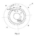
- the engine rotation sensor 9 includes a pulser 9a and a pickup 9b.
- the pulser 9a is disc-shaped, and a central portion thereof is coupled to a crankshaft 11 such that the pulser 9a rotates in conjunction with rotation of the crankshaft 11.
- Thirty-four teeth 12 are formed on an outer peripheral edge of the pulser 9a.
- the teeth 12 are provided in positions obtained by dividing the entire outer peripheral edge of the pulser 9a by thirty-six, and therefore tooth missing portions 13 exist in two tooth positions indicated by dotted lines. In other words, two teeth are missing.
- the teeth 12 are divided into four sections A to D at intervals of 90°, and numbers 0 to 8 are allocated respectively to the teeth 12 in the sections A to C.
- the pickup 9b is a magnetic sensor disposed in a position facing the teeth 12 in order to output a pulse signal to the ECU 8 electrically connected thereto every time a tooth 12 approaches during rotation of the pulser 9a.
- the ECU 8 to which the pulse signals are transmitted calculates the rotation speed on the basis of an interval between the pulse signals. Further, the ECU 8 calculates the crank angle on the basis of the tooth missing portions 13, at which pulse signals are not detected, and the number of pulse signals detected after the tooth missing portions 13.
- a low rotation speed case corresponds to a case in which the rotation speed of the diesel engine 1 is comparatively low, calculation of the fuel injection amount is started at a predetermined crank angle following the start of fuel injection into a certain cylinder, and calculation of the fuel injection amount of the cylinder (to be referred to hereafter as the first cylinder) that is first subjected to fuel injection after the start of the calculation is completed before a calculation completion limit angle.
- a high rotation speed case corresponds to a case in which the rotation speed of the diesel engine 1 increases such that when a crank angle range that can be used for the calculation, or in other words a calculation angle, remains constant, the actual time that can be used for the calculation decreases, and therefore, if calculation of the fuel injection amount is started at the same predetermined crank angle as the low rotation speed case, calculation of the fuel injection amount of the first cylinder cannot be completed before the calculation completion limit angle of the first cylinder.
- the rotation speed of the diesel engine 1 forming a boundary between the low rotation speed case and the high rotation speed case is set as a reference rotation speed and held in advance in the ECU 8.
- the ECU 8 When the predetermined crank angle is reached, the ECU 8 first compares the rotation speed of the diesel engine 1 with the reference rotation speed in order to select control corresponding to the low rotation speed case or control corresponding to the high rotation speed case, to be described below.
- the content of the control corresponding to the low rotation speed case and the control corresponding to the high rotation speed case will be described specifically below.
- the fuel injection amount denotes not only a total amount of fuel injected into each cylinder.
- the fuel may be divided into a plurality of injections, such as a main injection and a post-injection, before being injected into the respective cylinders, and therefore the fuel injection amount also includes a number of divided injections, as well as timings and amounts of the divided injections.
- Reference symbols #1 to #8 are allocated respectively to the eight cylinders 2 of the diesel engine 1 in the order of fuel injection. As shown in Fig. 3 , calculation of the fuel injection amount for the cylinder #1 begins when the pickup 9b (see Fig. 2 ) detects the tooth 12 allocated the number 1 in the section A of the pulser 9a, or in other words at a crank angle of 10°.
- the ECU 8 When the crank angle reaches 10°, the ECU 8 (see Fig. 1 ) first determines whether the low rotation speed case or the high rotation speed case is established. After determining that the low rotation speed case is established, the calculation unit 15 starts to calculate the fuel injection amount.
- the actual calculation of the fuel injection amount is a well known calculation based on the rotation speed of the diesel engine 1, accelerator opening, and so on, and therefore description thereof has been omitted.
- the calculation of the fuel injection amount is completed when the pickup 9b detects the tooth 12 allocated the number 6, for example, or in other words at a crank angle of 60°.
- the ECU 8 stores a calculation result Q# 1 in the storage area 16a corresponding to cylinder #1 (corresponding to the first cylinder).
- the ECU 8 stores the calculation result Q #1 in the storage area 16b corresponding to cylinder #2 to be subjected to fuel injection following cylinder #1 (hereafter, the cylinder that is subjected to fuel injection following the first cylinder will be referred to as the following cylinder, and in this case, cylinder #2 corresponds to the following cylinder).
- the ECU 8 issues a request command relating to fuel injection into cylinder #1 and based on the calculation result Q# 1 stored in the storage area 16a to the drive circuit 10, or in other words makes a reservation (omitted from Fig. 3 ).
- the drive circuit 10 executes fuel injection by opening or closing the solenoid valve 4 (see Fig. 1 ) of the injector 3 disposed in cylinder #1 following the elapse of a predetermined time.
- the request command issued to cylinder #1 at this time is calculated by performing separate correction processing on the calculation result Q #1 , i.e. the fuel injection amount stored in the storage area 16a, using the correction information corresponding to the cylinder, which is held in the storage area 16a.
- Calculation of the fuel injection amount for cylinder #2 is started using a similar method when the pickup 9b detects the tooth 12 allocated the number 1 in section B of the pulser 9a (see Fig. 2 ), or in other words at a crank angle of 100°.
- the calculation unit 15 stores a calculation result Q# 2 in the storage area 16b corresponding to cylinder #2.
- the calculation result Q #1 is already stored in the storage area 16b, and therefore the calculation result Q# 2 is overwritten.
- the calculation unit 15 stores the calculation result Q# 2 in the storage area 16c corresponding to cylinder #3 to be subjected to fuel injection following cylinder #2. Thereafter, fuel is injected into cylinder #2 using a method similar to that described above. Fuel injection into cylinder #3 thru cylinder #8 is performed in a similar manner, and when fuel injection into cylinder #8 is complete, fuel is injected into cylinder #1 again using a similar method.
- the ECU 8 performs a switch such that the calculation performed by the calculation unit 15 is advanced by one cylinder. More specifically, the calculation result Q #1 of the calculation that starts when the pickup 9b detects the tooth 12 allocated the number 1 in the section A of the pulser 9a is stored in the storage area 16b in order to be used for cylinder #2 (corresponding to the following cylinder). Similarly, the ECU 8 also stores the calculation result Q# 1 in the storage area 16c corresponding to cylinder #3 to be subjected to fuel injection following cylinder #2. The ECU 8 then performs the reservation processing in relation to cylinder #2 when the pickup 9b detects the tooth 12 allocated the number 7 in the section B. As a result, fuel is injected into cylinder #2 on the basis of the calculation result Q #1 stored in the storage area 16b and the correction information held in the storage area 16b.
- the calculation unit 15 starts to perform the calculation for the following cylinder rather than the first cylinder, and since a calculation result does not exist in relation to the first cylinder, the reservation processing performed on the drive circuit 10 in relation to the first cylinder is skipped, leading to a situation in which fuel injection into the first cylinder is missed or performed without making use of the calculation result.
- the calculation result Q #2 which was used to inject fuel into the first cylinder, or in other words cylinder #2, prior to the switch is used to inject fuel into the following cylinder, which is subjected to fuel injection following cylinder #2, or in other words cylinder #3 (i.e. stored in the storage areas 16c and 16d), and as a result, the calculation result for injecting fuel into cylinder #2 disappears.
- the calculation result (Q #1 calculated in the period of numbers 1 to 6 in section A of the pulser 9a is stored in the storage areas 16a and 16b, and therefore the ECU 8 can perform fuel injection immediately after the switch by performing the reservation processing on the drive circuit 10 on the basis of the calculation result Q #1 stored in the storage area 16b.
- a situation in which fuel injection into cylinder #2 is skipped can be prevented.
- a situation in which fuel injection into cylinder #2 is skipped can be prevented, but regardless of the timing of the switch, situations in which calculation results are skipped for the cylinders corresponding to the calculations performed by the calculation unit 15 can similarly be prevented from occurring.
- the calculation result generated by the calculation unit 15 is stored in two storage areas even in the high rotation speed case, but the present invention is not limited thereto.
- the calculation result is stored in two storage areas to prevent a situation in which a fuel injection calculation result is not performed in relation to the cylinder that is subjected to fuel injection immediately after a switch from the low rotation speed case to the high rotation speed case, and therefore, following a switch to the high rotation speed case, the calculation result may be stored only in the storage area corresponding to the cylinder on which the calculation result is to be used.
- the respective storage areas 16a to 16h hold the calculation results of the fuel injection amount and store the correction information corresponding to the respective cylinders.
- the present invention is not limited thereto, and instead, for example, the respective storage areas 16a to 16h may hold only the calculation results of the fuel injection amount. In this case, a different storage area may be provided and the correction information corresponding to the respective cylinders may be stored therein.
- calculation of the fuel injection amount for each cylinder is started when the pickup 9b detects the tooth 12 allocated the number 1 in the respective sections A to D.
- the present invention is not limited thereto, and by performing setting in advance, the calculation may be started when the pickup 9b detects a tooth 12 allocated an arbitrary number. In other words, the calculation may be started at an arbitrary preset crank angle.
- the diesel engine 1 is a V type eight cylinder diesel engine, but the present invention is not limited thereto, and any diesel engine having a plurality of cylinders, for example a line type engine or a horizontally opposed engine, may be used instead.
- the number of cylinders is not limited to eight, and the present invention may be used with more than eight cylinders and is particularly effective when the number of cylinders is large. Also note that the number of storage areas must be identical to the number of cylinders.
- a calculation result Q# 2 which was used to inject fuel into a cylinder #2 prior to the switch, is used to inject fuel into a cylinder #3, which is subjected to fuel injection following the cylinder #2, and as a result, the calculation result for injecting fuel into the cylinder #2 disappears.
- a calculation result Q# 1 calculated in the period of the numbers 1 to 6 in a section A of the pulser 9a is stored in a storage area 16b, and therefore an ECU 8 can inject fuel into the cylinder #2 immediately after the aforesaid switch by performing reservation processing on a drive circuit 10 on the basis of the calculation result Q #1 stored in the storage area 16b.
Landscapes
- Engineering & Computer Science (AREA)
- Chemical & Material Sciences (AREA)
- Combustion & Propulsion (AREA)
- Mechanical Engineering (AREA)
- General Engineering & Computer Science (AREA)
- Electrical Control Of Air Or Fuel Supplied To Internal-Combustion Engine (AREA)
Abstract
Description
- The present invention relates to a fuel injection control apparatus for a diesel engine.
- In recent years, common rail type diesel engines have gained prominence among diesel engines. In a common rail type diesel engine, split injection and so on can be performed easily by having a fuel injection control apparatus control energization time (valve opening time) of a fuel injection valve (injector), and therefore injection can be performed with a high degree of freedom. Incidentally, the fuel injection control apparatus typically starts to calculate fuel injection amounts for respective cylinders on the basis of a predetermined crank angle. To ensure that fuel is injected into the respective cylinders reliably, calculation of the fuel injection amounts must be completed at a timing before the start of fuel injection when injection is not impaired, or in other words before a calculation completion limit angle.
- Typically, an interval between the calculation start timing of the fuel injection amount and an injection energization start timing of the fuel injection valve is preferably as short as possible. The reason for this is that as time elapses, variations occur in information relating to operating conditions (engine rotation speed, load, pressure in a common rail, and so on) used in the calculation, and therefore control can be executed with a higher degree of precision as the aforementioned interval decreases. Meanwhile, the engine rotation speed of an automobile in particular varies within a wide range from a low rotation speed to a high rotation speed. Therefore, when the calculation start timing of the fuel injection amount is aligned with a high rotation speed side, the actual time from the start of calculation to the start of injection energization increases on a low rotation speed side, leading to a reduction in precision. When the calculation start timing of the fuel injection amount is aligned with the low rotation speed side, on the other hand, the calculation is not completed in time on the high rotation speed side.
- As a countermeasure to this problem, Japanese Patent Application Publication No.
2004-150321 - A diesel engine described in Japanese Patent Application Publication No.
2004-150321 - Measures may easily be taken to simplify the content of the calculation processing or to employ a high-performance ECU in the fuel injection amount control apparatus. In this case, however, new problems such as deterioration of the precision of the fuel injection amount control and cost increases arise.
- The present invention has been designed to solve these problems, and an object thereof is to provide a fuel injection control apparatus that can inject fuel into respective cylinders without missing any of the cylinders and without causing the problems described above.
- The present invention provides a fuel injection control apparatus for a diesel engine having a plurality of cylinders, the fuel injection control apparatus comprising: a calculation unit that calculates a fuel injection amount for each cylinder; and a storage unit that has a storage area corresponding to each cylinder and stores in a corresponding storage area a calculation result generated by the calculation unit, the fuel injection control apparatus being characterized in that, when the rotation speed of the diesel engine is equal to or lower than a preset reference rotation speed, the calculation result is stored in a corresponding storage area as a fuel injection amount for each of two cylinders, namely a first cylinder, which is a cylinder first subjected to fuel injection following the start of the calculation, and a following cylinder, which is a cylinder subjected to fuel injection following the first cylinder, and when the rotation speed of the diesel engine is higher than the reference rotation speed, the calculation result is stored in the corresponding storage area as at least the fuel injection amount of the following cylinder.
- In the accompanying drawings:
-
Fig. 1 is a schematic constitutional diagram of a diesel engine including a fuel injection control apparatus according to an embodiment of the present invention; -
Fig. 2 is a view illustrating the constitution of an engine rotation sensor provided in the fuel injection control apparatus according to this embodiment; and -
Fig. 3 is a view illustrating an operation of the fuel injection control apparatus according to this embodiment. - An embodiment of the present invention will be described below on the basis of the attached drawings.
-
Fig. 1 shows the constitution of a diesel engine including a fuel injection control apparatus according to an embodiment of the present invention. Adiesel engine 1 is a V type eight-cylinder common rail diesel engine. Each cylinder 2 (only one cylinder is shown inFig. 1 ) is provided with aninjector 3 for injecting fuel into the cylinder. Eachinjector 3 is provided with asolenoid valve 4 for ON/OFF control of the fuel injection. - The
injector 3 is connected to acommon rail 5 by a high pressure fuel pipe 14. Fuel is accumulated in thecommon rail 5 in a high pressure state such that when thesolenoid valve 4 is opened, the fuel is fed through the fuel pipe 14 by an internal pressure of thecommon rail 5 and injected from theinjector 3. The fuel is supplied to thecommon rail 5 from afuel tank 7 by apump 6 such that the internal pressure of thecommon rail 5 is maintained at a predetermined pressure. - The
diesel engine 1 is further provided with anECU 8 for controlling an operation of thediesel engine 1. The ECU 8 is provided with acalculation unit 15 for calculating a fuel injection amount on the basis of operating conditions of thediesel engine 1, and astorage unit 16 for storing information relating to fuel injection into therespective cylinders 2. Thestorage unit 16 includes eightstorage areas 16a to 16h corresponding to therespective cylinders 2, and thestorage areas 16a to 16h respectively store calculation results generated by thecalculation unit 15 in relation to the fuel injection amounts for therespective cylinders 2. Further, correction information corresponding to acorresponding cylinder 2 is stored separately in eachstorage area 16a to 16h. The correction information is based on temporal deterioration of theinjector 3, a degree of blockage of an injection hole, and so on, and is used for correction when a command value of open/close control of therespective solenoid valves 4 is calculated on the basis of the fuel injection amount. Conventional means, such as a method of calculating a correction value in relation to temporal deterioration disclosed in Japanese Patent Application Publication No.2002-89333 engine rotation sensor 9 for detecting a crank angle and a rotation speed of thediesel engine 1 and adrive circuit 10 are electrically connected to theECU 8. Thesolenoid valve 4 is electrically connected to thedrive circuit 10. - As shown in
Fig. 2 , theengine rotation sensor 9 includes a pulser 9a and apickup 9b. The pulser 9a is disc-shaped, and a central portion thereof is coupled to acrankshaft 11 such that the pulser 9a rotates in conjunction with rotation of thecrankshaft 11. Thirty-fourteeth 12 are formed on an outer peripheral edge of the pulser 9a. Theteeth 12 are provided in positions obtained by dividing the entire outer peripheral edge of the pulser 9a by thirty-six, and therefore toothmissing portions 13 exist in two tooth positions indicated by dotted lines. In other words, two teeth are missing. Theteeth 12 are divided into four sections A to D at intervals of 90°, andnumbers 0 to 8 are allocated respectively to theteeth 12 in the sections A to C. Only seven teeth exist in the section D including the toothmissing portions 13, and thereforenumbers 0 to 6 are allocated respectively to theteeth 12 in the section D. Thepickup 9b is a magnetic sensor disposed in a position facing theteeth 12 in order to output a pulse signal to theECU 8 electrically connected thereto every time atooth 12 approaches during rotation of the pulser 9a. TheECU 8 to which the pulse signals are transmitted calculates the rotation speed on the basis of an interval between the pulse signals. Further, theECU 8 calculates the crank angle on the basis of the toothmissing portions 13, at which pulse signals are not detected, and the number of pulse signals detected after the toothmissing portions 13. - Next, operation of the fuel injection control apparatus according to this embodiment will be described.
- In this embodiment, a low rotation speed case corresponds to a case in which the rotation speed of the
diesel engine 1 is comparatively low, calculation of the fuel injection amount is started at a predetermined crank angle following the start of fuel injection into a certain cylinder, and calculation of the fuel injection amount of the cylinder (to be referred to hereafter as the first cylinder) that is first subjected to fuel injection after the start of the calculation is completed before a calculation completion limit angle. Further, a high rotation speed case corresponds to a case in which the rotation speed of thediesel engine 1 increases such that when a crank angle range that can be used for the calculation, or in other words a calculation angle, remains constant, the actual time that can be used for the calculation decreases, and therefore, if calculation of the fuel injection amount is started at the same predetermined crank angle as the low rotation speed case, calculation of the fuel injection amount of the first cylinder cannot be completed before the calculation completion limit angle of the first cylinder. Note that the rotation speed of thediesel engine 1 forming a boundary between the low rotation speed case and the high rotation speed case is set as a reference rotation speed and held in advance in theECU 8. When the predetermined crank angle is reached, theECU 8 first compares the rotation speed of thediesel engine 1 with the reference rotation speed in order to select control corresponding to the low rotation speed case or control corresponding to the high rotation speed case, to be described below. The content of the control corresponding to the low rotation speed case and the control corresponding to the high rotation speed case will be described specifically below. - Note that the fuel injection amount denotes not only a total amount of fuel injected into each cylinder. Depending on the operating conditions of the
diesel engine 1, the fuel may be divided into a plurality of injections, such as a main injection and a post-injection, before being injected into the respective cylinders, and therefore the fuel injection amount also includes a number of divided injections, as well as timings and amounts of the divided injections. - The low rotation speed case will now be described in detail.
Reference symbols # 1 to #8 are allocated respectively to the eightcylinders 2 of thediesel engine 1 in the order of fuel injection. As shown inFig. 3 , calculation of the fuel injection amount for thecylinder # 1 begins when thepickup 9b (seeFig. 2 ) detects thetooth 12 allocated thenumber 1 in the section A of the pulser 9a, or in other words at a crank angle of 10°. - When the crank angle reaches 10°, the ECU 8 (see
Fig. 1 ) first determines whether the low rotation speed case or the high rotation speed case is established. After determining that the low rotation speed case is established, thecalculation unit 15 starts to calculate the fuel injection amount. The actual calculation of the fuel injection amount is a well known calculation based on the rotation speed of thediesel engine 1, accelerator opening, and so on, and therefore description thereof has been omitted. The calculation of the fuel injection amount is completed when thepickup 9b detects thetooth 12 allocated thenumber 6, for example, or in other words at a crank angle of 60°. When the calculation of the fuel injection amount is complete, theECU 8 stores a calculation result Q#1 in thestorage area 16a corresponding to cylinder #1 (corresponding to the first cylinder). Simultaneously, theECU 8 stores the calculation result Q#1 in thestorage area 16b corresponding tocylinder # 2 to be subjected to fuel injection following cylinder #1 (hereafter, the cylinder that is subjected to fuel injection following the first cylinder will be referred to as the following cylinder, and in this case,cylinder # 2 corresponds to the following cylinder). - At a predetermined timing following completion of the calculation of the fuel injection amount, for example when the
pickup 9b detects thetooth 12 allocated thenumber 7, or in other words at a crank angle of 70°, theECU 8 issues a request command relating to fuel injection intocylinder # 1 and based on the calculation result Q#1 stored in thestorage area 16a to thedrive circuit 10, or in other words makes a reservation (omitted fromFig. 3 ). As a result of this reservation processing, thedrive circuit 10 executes fuel injection by opening or closing the solenoid valve 4 (seeFig. 1 ) of theinjector 3 disposed incylinder # 1 following the elapse of a predetermined time. The request command issued tocylinder # 1 at this time is calculated by performing separate correction processing on the calculation result Q#1, i.e. the fuel injection amount stored in thestorage area 16a, using the correction information corresponding to the cylinder, which is held in thestorage area 16a. - Calculation of the fuel injection amount for
cylinder # 2 is started using a similar method when thepickup 9b detects thetooth 12 allocated thenumber 1 in section B of the pulser 9a (seeFig. 2 ), or in other words at a crank angle of 100°. In this case, thecalculation unit 15 stores a calculation result Q#2 in thestorage area 16b corresponding tocylinder # 2. The calculation result Q#1 is already stored in thestorage area 16b, and therefore the calculation result Q#2 is overwritten. Simultaneously, thecalculation unit 15 stores the calculation result Q#2 in thestorage area 16c corresponding tocylinder # 3 to be subjected to fuel injection followingcylinder # 2. Thereafter, fuel is injected intocylinder # 2 using a method similar to that described above. Fuel injection intocylinder # 3 thrucylinder # 8 is performed in a similar manner, and when fuel injection intocylinder # 8 is complete, fuel is injected intocylinder # 1 again using a similar method. - Processing performed when the
ECU 8 determines that a high rotation speed case is established will now be described in detail. TheECU 8 performs a switch such that the calculation performed by thecalculation unit 15 is advanced by one cylinder. More specifically, the calculation result Q#1 of the calculation that starts when thepickup 9b detects thetooth 12 allocated thenumber 1 in the section A of the pulser 9a is stored in thestorage area 16b in order to be used for cylinder #2 (corresponding to the following cylinder). Similarly, theECU 8 also stores the calculation result Q#1 in thestorage area 16c corresponding tocylinder # 3 to be subjected to fuel injection followingcylinder # 2. TheECU 8 then performs the reservation processing in relation tocylinder # 2 when thepickup 9b detects thetooth 12 allocated thenumber 7 in the section B. As a result, fuel is injected intocylinder # 2 on the basis of the calculation result Q#1 stored in thestorage area 16b and the correction information held in thestorage area 16b. - If the calculation result is stored in only one storage area when the rotation speed of the
diesel engine 1 switches from a low rotation speed to a high rotation speed such that the switch described above is performed, thecalculation unit 15 starts to perform the calculation for the following cylinder rather than the first cylinder, and since a calculation result does not exist in relation to the first cylinder, the reservation processing performed on thedrive circuit 10 in relation to the first cylinder is skipped, leading to a situation in which fuel injection into the first cylinder is missed or performed without making use of the calculation result. For example, if the switch described above is performed before performing the calculation in the period of thenumbers 1 to 6 in section B of the pulser 9a, the calculation result Q#2, which was used to inject fuel into the first cylinder, or in otherwords cylinder # 2, prior to the switch is used to inject fuel into the following cylinder, which is subjected to fuel injection followingcylinder # 2, or in other words cylinder #3 (i.e. stored in thestorage areas cylinder # 2 disappears. However, the calculation result (Q#1 calculated in the period ofnumbers 1 to 6 in section A of the pulser 9a is stored in thestorage areas ECU 8 can perform fuel injection immediately after the switch by performing the reservation processing on thedrive circuit 10 on the basis of the calculation result Q#1 stored in thestorage area 16b. As a result, a situation in which fuel injection intocylinder # 2 is skipped can be prevented. In this example, a situation in which fuel injection intocylinder # 2 is skipped can be prevented, but regardless of the timing of the switch, situations in which calculation results are skipped for the cylinders corresponding to the calculations performed by thecalculation unit 15 can similarly be prevented from occurring. - Conversely, when the high rotation speed case switches to the low rotation speed case, a modification should be made so that the calculation result being calculated at the time of the switch is used as the fuel injection amount for the original cylinder. For example, when the high rotation speed case switches to the low rotation speed case during the calculation performed in the period of the
numbers 1 to 6 in the section B of the pulser 9a, the calculation result Q#2 should be used to inject fuel intocylinder # 2 rather thancylinder # 3. - By switching from control in which the calculation result of the fuel injection amount is used to inject fuel into the cylinder that is first subjected to fuel injection following the start of the calculation to control in which the calculation result is used to inject fuel into the cylinder that is next subjected to fuel injection on the basis of the rotation speed of the
diesel engine 1 in this manner, fuel injection can be performed without missing any of the cylinders. - In this embodiment, the calculation result generated by the
calculation unit 15 is stored in two storage areas even in the high rotation speed case, but the present invention is not limited thereto. The calculation result is stored in two storage areas to prevent a situation in which a fuel injection calculation result is not performed in relation to the cylinder that is subjected to fuel injection immediately after a switch from the low rotation speed case to the high rotation speed case, and therefore, following a switch to the high rotation speed case, the calculation result may be stored only in the storage area corresponding to the cylinder on which the calculation result is to be used. - In this embodiment, the
respective storage areas 16a to 16h hold the calculation results of the fuel injection amount and store the correction information corresponding to the respective cylinders. However, the present invention is not limited thereto, and instead, for example, therespective storage areas 16a to 16h may hold only the calculation results of the fuel injection amount. In this case, a different storage area may be provided and the correction information corresponding to the respective cylinders may be stored therein. - In this embodiment, calculation of the fuel injection amount for each cylinder is started when the
pickup 9b detects thetooth 12 allocated thenumber 1 in the respective sections A to D. However, the present invention is not limited thereto, and by performing setting in advance, the calculation may be started when thepickup 9b detects atooth 12 allocated an arbitrary number. In other words, the calculation may be started at an arbitrary preset crank angle. - In this embodiment, the
diesel engine 1 is a V type eight cylinder diesel engine, but the present invention is not limited thereto, and any diesel engine having a plurality of cylinders, for example a line type engine or a horizontally opposed engine, may be used instead. Note that the number of cylinders is not limited to eight, and the present invention may be used with more than eight cylinders and is particularly effective when the number of cylinders is large. Also note that the number of storage areas must be identical to the number of cylinders. - When a low rotation speed switches to a high rotation speed before a calculation is performed in a period of
numbers 1 to 6 in a section B of a pulser 9a, a calculation result Q#2, which was used to inject fuel into acylinder # 2 prior to the switch, is used to inject fuel into acylinder # 3, which is subjected to fuel injection following thecylinder # 2, and as a result, the calculation result for injecting fuel into thecylinder # 2 disappears. However, a calculation result Q#1 calculated in the period of thenumbers 1 to 6 in a section A of the pulser 9a is stored in astorage area 16b, and therefore anECU 8 can inject fuel into thecylinder # 2 immediately after the aforesaid switch by performing reservation processing on adrive circuit 10 on the basis of the calculation result Q#1 stored in thestorage area 16b.
Claims (5)
- A fuel injection control apparatus for a diesel engine having a plurality of cylinders, said fuel injection control apparatus comprising:a calculation unit that calculates a fuel injection amount for each cylinder; anda storage unit that has a storage area corresponding to each cylinder and stores in a corresponding storage area a calculation result generated by said calculation unit,said fuel injection control apparatus being characterized in that,when the rotation speed of said diesel engine is equal to or lower than a preset reference rotation speed, said calculation result is stored in a corresponding storage area as a fuel injection amount for each of two cylinders, namely a first cylinder, which is a cylinder first subjected to fuel injection following the start of said calculation, and a following cylinder, which is a cylinder subjected to fuel injection following said first cylinder, andwhen said rotation speed of said diesel engine is higher than said reference rotation speed, said calculation result is stored in said corresponding storage area as at least said fuel injection amount of said following cylinder.
- The fuel injection control apparatus according to claim 1, characterized in that a calculation result, generated in a fuel injection amount calculation started first after said rotation speed of said diesel engine rises above said reference rotation speed, is stored in said corresponding storage area as at least said fuel injection amount of said following cylinder, and
a calculation result, generated in a fuel injection amount calculation performed immediately before said fuel injection amount calculation started first after said rotation speed of said diesel engine rises above said reference rotation speed, is used as said fuel injection amount of said first cylinder. - The fuel injection control apparatus according to claim 1 or 2, characterized in that each of said cylinders is provided with an injector for injecting a fuel, and
said calculation results relating to said respective cylinders are overwritten to and saved in said respective storage areas together with correction information relating to said injector of said corresponding cylinder. - The fuel injection control apparatus according to any one of claims 1 to 3, comprising:an ECU including said calculation unit and said storage unit; anda drive circuit that drive-controls said injectors on the basis of a signal from said ECU,said fuel injection control apparatus being characterized in that said drive circuit ON/OFF controls said corresponding injector on the basis of said calculation result and said correction information stored in said respective storage areas.
- The fuel injection control apparatus according to any one of claims 1 to 4, characterized in that said calculation of said fuel injection amount for each of said cylinders is started at a preset crank angle.
Applications Claiming Priority (1)
| Application Number | Priority Date | Filing Date | Title |
|---|---|---|---|
| JP2010203272A JP5182995B2 (en) | 2010-09-10 | 2010-09-10 | Fuel injection control device |
Publications (3)
| Publication Number | Publication Date |
|---|---|
| EP2428668A2 true EP2428668A2 (en) | 2012-03-14 |
| EP2428668A3 EP2428668A3 (en) | 2016-08-17 |
| EP2428668B1 EP2428668B1 (en) | 2024-05-01 |
Family
ID=44674365
Family Applications (1)
| Application Number | Title | Priority Date | Filing Date |
|---|---|---|---|
| EP11179456.6A Active EP2428668B1 (en) | 2010-09-10 | 2011-08-31 | Fuel injection control apparatus |
Country Status (2)
| Country | Link |
|---|---|
| EP (1) | EP2428668B1 (en) |
| JP (1) | JP5182995B2 (en) |
Families Citing this family (2)
| Publication number | Priority date | Publication date | Assignee | Title |
|---|---|---|---|---|
| JP7172063B2 (en) * | 2018-03-02 | 2022-11-16 | 株式会社デンソー | Injection control device |
| JP7583235B2 (en) | 2021-12-23 | 2024-11-14 | 株式会社クボタ | Injector Control Unit |
Citations (2)
| Publication number | Priority date | Publication date | Assignee | Title |
|---|---|---|---|---|
| JP2002089333A (en) | 2000-07-14 | 2002-03-27 | Toyota Motor Corp | Engine fuel injection control device |
| JP2004150321A (en) | 2002-10-29 | 2004-05-27 | Toyota Motor Corp | Internal combustion engine output control method and apparatus |
Family Cites Families (10)
| Publication number | Priority date | Publication date | Assignee | Title |
|---|---|---|---|---|
| DE3923479A1 (en) * | 1989-07-15 | 1991-01-24 | Bosch Gmbh Robert | SEQUENTIAL FUEL INJECTION PROCESS |
| JPH0422724A (en) * | 1990-05-18 | 1992-01-27 | Hitachi Ltd | Control method for fuel injection of engine |
| DE4319881B4 (en) * | 1993-06-16 | 2006-10-26 | Robert Bosch Gmbh | Method for processing interrupt signals of an interrupt source |
| IT1268053B1 (en) * | 1994-03-10 | 1997-02-20 | Marelli Autronica | DEVICE FOR CONTROL OF FUEL INJECTION IN A THERMAL ENGINE. |
| JP2812240B2 (en) * | 1995-04-12 | 1998-10-22 | トヨタ自動車株式会社 | Fuel injection control device for electronically controlled diesel engine |
| JP3089997B2 (en) * | 1995-08-11 | 2000-09-18 | 三菱自動車工業株式会社 | Cylinder identification system for a multi-cylinder internal combustion engine |
| JP2001248493A (en) * | 2000-03-01 | 2001-09-14 | Denso Corp | Pulse output control device |
| DE10041443A1 (en) * | 2000-08-23 | 2002-03-07 | Bosch Gmbh Robert | Method for operating an internal combustion engine and corresponding device |
| DE102006048174A1 (en) * | 2006-10-10 | 2008-04-17 | Robert Bosch Gmbh | Injection system for controlling cylinders of combustion engine for motor vehicle, has multi-core processor with main processors and computation of control start and control duration is distributed in main processors |
| DE102008043971A1 (en) * | 2008-11-21 | 2010-05-27 | Robert Bosch Gmbh | Method for determining control parameter for controlling electrically or electronically regulated injection for combustion engine, involves utilizing group of control parameters and another group of control parameters for controlling |
-
2010
- 2010-09-10 JP JP2010203272A patent/JP5182995B2/en active Active
-
2011
- 2011-08-31 EP EP11179456.6A patent/EP2428668B1/en active Active
Patent Citations (2)
| Publication number | Priority date | Publication date | Assignee | Title |
|---|---|---|---|---|
| JP2002089333A (en) | 2000-07-14 | 2002-03-27 | Toyota Motor Corp | Engine fuel injection control device |
| JP2004150321A (en) | 2002-10-29 | 2004-05-27 | Toyota Motor Corp | Internal combustion engine output control method and apparatus |
Also Published As
| Publication number | Publication date |
|---|---|
| EP2428668A3 (en) | 2016-08-17 |
| EP2428668B1 (en) | 2024-05-01 |
| JP5182995B2 (en) | 2013-04-17 |
| JP2012057581A (en) | 2012-03-22 |
Similar Documents
| Publication | Publication Date | Title |
|---|---|---|
| EP3109443B1 (en) | Fuel injection device for internal combustion engine | |
| US6786212B1 (en) | Method for preventing a reverse rotation of an engine | |
| JP2005171931A (en) | Fuel injection control device | |
| US11053882B2 (en) | Fuel injection valve control device and fuel injection valve control method | |
| US7367323B2 (en) | Eight-cylinder engine | |
| EP2428668A2 (en) | Fuel injection control apparatus | |
| CN100357580C (en) | Fuel injection system of internal combustion engine | |
| AU2012211828B2 (en) | Fuel injection control device | |
| KR100367036B1 (en) | Fuel injection control system for internal combustion engine | |
| JP7035466B2 (en) | Fuel injection control device | |
| EP2693030A1 (en) | Fuel injection control device | |
| JP2005163559A (en) | Accumulated fuel injection system | |
| JP6252327B2 (en) | Fuel supply control device | |
| US7711471B2 (en) | Fuel injection control method | |
| JP4214642B2 (en) | Accumulated fuel injection system | |
| JP3807293B2 (en) | Fuel injection control device for internal combustion engine | |
| JPH06264803A (en) | Abnormality diagnostic device of fuel injection device | |
| JP2009030566A (en) | Failure diagnosis device for fuel injection device | |
| JP4000650B2 (en) | Accumulated fuel injection system for diesel engines | |
| JP2010138754A (en) | Fuel injection control device for internal combustion engine | |
| JP7494769B2 (en) | Control device for internal combustion engine system | |
| JP2002047984A (en) | Abnormality diagnosis device for high pressure fuel supply system of internal combustion engine | |
| AU2012268869B2 (en) | Fuel injection controller | |
| JPH05195848A (en) | Fuel injector and fuel injection valve drive circuit | |
| JPH1054292A (en) | Fuel supply device |
Legal Events
| Date | Code | Title | Description |
|---|---|---|---|
| 17P | Request for examination filed |
Effective date: 20110831 |
|
| AK | Designated contracting states |
Kind code of ref document: A2 Designated state(s): AL AT BE BG CH CY CZ DE DK EE ES FI FR GB GR HR HU IE IS IT LI LT LU LV MC MK MT NL NO PL PT RO RS SE SI SK SM TR |
|
| AX | Request for extension of the european patent |
Extension state: BA ME |
|
| PUAI | Public reference made under article 153(3) epc to a published international application that has entered the european phase |
Free format text: ORIGINAL CODE: 0009012 |
|
| RAP1 | Party data changed (applicant data changed or rights of an application transferred) |
Owner name: KABUSHIKI KAISHA TOYOTA JIDOSHOKKI Owner name: TOYOTA JIDOSHA KABUSHIKI KAISHA |
|
| PUAL | Search report despatched |
Free format text: ORIGINAL CODE: 0009013 |
|
| AK | Designated contracting states |
Kind code of ref document: A3 Designated state(s): AL AT BE BG CH CY CZ DE DK EE ES FI FR GB GR HR HU IE IS IT LI LT LU LV MC MK MT NL NO PL PT RO RS SE SI SK SM TR |
|
| AX | Request for extension of the european patent |
Extension state: BA ME |
|
| RIC1 | Information provided on ipc code assigned before grant |
Ipc: G06F 9/48 20060101AFI20160712BHEP Ipc: F02B 75/18 20060101ALN20160712BHEP Ipc: F02D 41/40 20060101ALN20160712BHEP Ipc: F02D 41/10 20060101ALI20160712BHEP Ipc: F02D 41/00 20060101ALI20160712BHEP Ipc: G01P 3/488 20060101ALI20160712BHEP Ipc: F02P 7/067 20060101ALN20160712BHEP Ipc: F02D 41/26 20060101ALI20160712BHEP Ipc: F02D 41/24 20060101ALI20160712BHEP |
|
| STAA | Information on the status of an ep patent application or granted ep patent |
Free format text: STATUS: EXAMINATION IS IN PROGRESS |
|
| 17Q | First examination report despatched |
Effective date: 20210503 |
|
| REG | Reference to a national code |
Ref country code: DE Ref legal event code: R079 Ref document number: 602011074754 Country of ref document: DE Free format text: PREVIOUS MAIN CLASS: F02D0041000000 Ipc: G06F0009480000 Ref country code: DE Ref legal event code: R079 Free format text: PREVIOUS MAIN CLASS: F02D0041000000 Ipc: G06F0009480000 |
|
| GRAP | Despatch of communication of intention to grant a patent |
Free format text: ORIGINAL CODE: EPIDOSNIGR1 |
|
| STAA | Information on the status of an ep patent application or granted ep patent |
Free format text: STATUS: GRANT OF PATENT IS INTENDED |
|
| RIC1 | Information provided on ipc code assigned before grant |
Ipc: F02D 41/40 20060101ALN20231107BHEP Ipc: F02B 75/18 20060101ALN20231107BHEP Ipc: F02P 7/067 20060101ALN20231107BHEP Ipc: F02D 41/10 20060101ALI20231107BHEP Ipc: F02D 41/24 20060101ALI20231107BHEP Ipc: F02D 41/00 20060101ALI20231107BHEP Ipc: G01P 3/488 20060101ALI20231107BHEP Ipc: F02D 41/26 20060101ALI20231107BHEP Ipc: G06F 9/48 20060101AFI20231107BHEP |
|
| INTG | Intention to grant announced |
Effective date: 20231128 |
|
| GRAS | Grant fee paid |
Free format text: ORIGINAL CODE: EPIDOSNIGR3 |
|
| GRAA | (expected) grant |
Free format text: ORIGINAL CODE: 0009210 |
|
| STAA | Information on the status of an ep patent application or granted ep patent |
Free format text: STATUS: THE PATENT HAS BEEN GRANTED |
|
| RAP1 | Party data changed (applicant data changed or rights of an application transferred) |
Owner name: KABUSHIKI KAISHA TOYOTA JIDOSHOKKI |
|
| P01 | Opt-out of the competence of the unified patent court (upc) registered |
Effective date: 20240318 |
|
| AK | Designated contracting states |
Kind code of ref document: B1 Designated state(s): AL AT BE BG CH CY CZ DE DK EE ES FI FR GB GR HR HU IE IS IT LI LT LU LV MC MK MT NL NO PL PT RO RS SE SI SK SM TR |
|
| REG | Reference to a national code |
Ref country code: GB Ref legal event code: FG4D |
|
| REG | Reference to a national code |
Ref country code: CH Ref legal event code: EP |
|
| REG | Reference to a national code |
Ref country code: DE Ref legal event code: R096 Ref document number: 602011074754 Country of ref document: DE |
|
| REG | Reference to a national code |
Ref country code: IE Ref legal event code: FG4D |
|
| REG | Reference to a national code |
Ref country code: LT Ref legal event code: MG9D |
|
| REG | Reference to a national code |
Ref country code: NL Ref legal event code: MP Effective date: 20240501 |
|
| PG25 | Lapsed in a contracting state [announced via postgrant information from national office to epo] |
Ref country code: IS Free format text: LAPSE BECAUSE OF FAILURE TO SUBMIT A TRANSLATION OF THE DESCRIPTION OR TO PAY THE FEE WITHIN THE PRESCRIBED TIME-LIMIT Effective date: 20240901 |
|
| PG25 | Lapsed in a contracting state [announced via postgrant information from national office to epo] |
Ref country code: BG Free format text: LAPSE BECAUSE OF FAILURE TO SUBMIT A TRANSLATION OF THE DESCRIPTION OR TO PAY THE FEE WITHIN THE PRESCRIBED TIME-LIMIT Effective date: 20240501 |
|
| PG25 | Lapsed in a contracting state [announced via postgrant information from national office to epo] |
Ref country code: FI Free format text: LAPSE BECAUSE OF FAILURE TO SUBMIT A TRANSLATION OF THE DESCRIPTION OR TO PAY THE FEE WITHIN THE PRESCRIBED TIME-LIMIT Effective date: 20240501 Ref country code: HR Free format text: LAPSE BECAUSE OF FAILURE TO SUBMIT A TRANSLATION OF THE DESCRIPTION OR TO PAY THE FEE WITHIN THE PRESCRIBED TIME-LIMIT Effective date: 20240501 |
|
| PG25 | Lapsed in a contracting state [announced via postgrant information from national office to epo] |
Ref country code: GR Free format text: LAPSE BECAUSE OF FAILURE TO SUBMIT A TRANSLATION OF THE DESCRIPTION OR TO PAY THE FEE WITHIN THE PRESCRIBED TIME-LIMIT Effective date: 20240802 |
|
| PG25 | Lapsed in a contracting state [announced via postgrant information from national office to epo] |
Ref country code: PT Free format text: LAPSE BECAUSE OF FAILURE TO SUBMIT A TRANSLATION OF THE DESCRIPTION OR TO PAY THE FEE WITHIN THE PRESCRIBED TIME-LIMIT Effective date: 20240902 |
|
| REG | Reference to a national code |
Ref country code: AT Ref legal event code: MK05 Ref document number: 1683319 Country of ref document: AT Kind code of ref document: T Effective date: 20240501 |
|
| PG25 | Lapsed in a contracting state [announced via postgrant information from national office to epo] |
Ref country code: NL Free format text: LAPSE BECAUSE OF FAILURE TO SUBMIT A TRANSLATION OF THE DESCRIPTION OR TO PAY THE FEE WITHIN THE PRESCRIBED TIME-LIMIT Effective date: 20240501 |
|
| PG25 | Lapsed in a contracting state [announced via postgrant information from national office to epo] |
Ref country code: ES Free format text: LAPSE BECAUSE OF FAILURE TO SUBMIT A TRANSLATION OF THE DESCRIPTION OR TO PAY THE FEE WITHIN THE PRESCRIBED TIME-LIMIT Effective date: 20240501 |
|
| PG25 | Lapsed in a contracting state [announced via postgrant information from national office to epo] |
Ref country code: AT Free format text: LAPSE BECAUSE OF FAILURE TO SUBMIT A TRANSLATION OF THE DESCRIPTION OR TO PAY THE FEE WITHIN THE PRESCRIBED TIME-LIMIT Effective date: 20240501 |
|
| PG25 | Lapsed in a contracting state [announced via postgrant information from national office to epo] |
Ref country code: PL Free format text: LAPSE BECAUSE OF FAILURE TO SUBMIT A TRANSLATION OF THE DESCRIPTION OR TO PAY THE FEE WITHIN THE PRESCRIBED TIME-LIMIT Effective date: 20240501 |
|
| PG25 | Lapsed in a contracting state [announced via postgrant information from national office to epo] |
Ref country code: LV Free format text: LAPSE BECAUSE OF FAILURE TO SUBMIT A TRANSLATION OF THE DESCRIPTION OR TO PAY THE FEE WITHIN THE PRESCRIBED TIME-LIMIT Effective date: 20240501 |
|
| PG25 | Lapsed in a contracting state [announced via postgrant information from national office to epo] |
Ref country code: PT Free format text: LAPSE BECAUSE OF FAILURE TO SUBMIT A TRANSLATION OF THE DESCRIPTION OR TO PAY THE FEE WITHIN THE PRESCRIBED TIME-LIMIT Effective date: 20240902 Ref country code: PL Free format text: LAPSE BECAUSE OF FAILURE TO SUBMIT A TRANSLATION OF THE DESCRIPTION OR TO PAY THE FEE WITHIN THE PRESCRIBED TIME-LIMIT Effective date: 20240501 Ref country code: NO Free format text: LAPSE BECAUSE OF FAILURE TO SUBMIT A TRANSLATION OF THE DESCRIPTION OR TO PAY THE FEE WITHIN THE PRESCRIBED TIME-LIMIT Effective date: 20240801 Ref country code: NL Free format text: LAPSE BECAUSE OF FAILURE TO SUBMIT A TRANSLATION OF THE DESCRIPTION OR TO PAY THE FEE WITHIN THE PRESCRIBED TIME-LIMIT Effective date: 20240501 Ref country code: LV Free format text: LAPSE BECAUSE OF FAILURE TO SUBMIT A TRANSLATION OF THE DESCRIPTION OR TO PAY THE FEE WITHIN THE PRESCRIBED TIME-LIMIT Effective date: 20240501 Ref country code: IS Free format text: LAPSE BECAUSE OF FAILURE TO SUBMIT A TRANSLATION OF THE DESCRIPTION OR TO PAY THE FEE WITHIN THE PRESCRIBED TIME-LIMIT Effective date: 20240901 Ref country code: HR Free format text: LAPSE BECAUSE OF FAILURE TO SUBMIT A TRANSLATION OF THE DESCRIPTION OR TO PAY THE FEE WITHIN THE PRESCRIBED TIME-LIMIT Effective date: 20240501 Ref country code: GR Free format text: LAPSE BECAUSE OF FAILURE TO SUBMIT A TRANSLATION OF THE DESCRIPTION OR TO PAY THE FEE WITHIN THE PRESCRIBED TIME-LIMIT Effective date: 20240802 Ref country code: FI Free format text: LAPSE BECAUSE OF FAILURE TO SUBMIT A TRANSLATION OF THE DESCRIPTION OR TO PAY THE FEE WITHIN THE PRESCRIBED TIME-LIMIT Effective date: 20240501 Ref country code: ES Free format text: LAPSE BECAUSE OF FAILURE TO SUBMIT A TRANSLATION OF THE DESCRIPTION OR TO PAY THE FEE WITHIN THE PRESCRIBED TIME-LIMIT Effective date: 20240501 Ref country code: BG Free format text: LAPSE BECAUSE OF FAILURE TO SUBMIT A TRANSLATION OF THE DESCRIPTION OR TO PAY THE FEE WITHIN THE PRESCRIBED TIME-LIMIT Effective date: 20240501 Ref country code: AT Free format text: LAPSE BECAUSE OF FAILURE TO SUBMIT A TRANSLATION OF THE DESCRIPTION OR TO PAY THE FEE WITHIN THE PRESCRIBED TIME-LIMIT Effective date: 20240501 Ref country code: RS Free format text: LAPSE BECAUSE OF FAILURE TO SUBMIT A TRANSLATION OF THE DESCRIPTION OR TO PAY THE FEE WITHIN THE PRESCRIBED TIME-LIMIT Effective date: 20240801 |
|
| PG25 | Lapsed in a contracting state [announced via postgrant information from national office to epo] |
Ref country code: DK Free format text: LAPSE BECAUSE OF FAILURE TO SUBMIT A TRANSLATION OF THE DESCRIPTION OR TO PAY THE FEE WITHIN THE PRESCRIBED TIME-LIMIT Effective date: 20240501 |
|
| PG25 | Lapsed in a contracting state [announced via postgrant information from national office to epo] |
Ref country code: EE Free format text: LAPSE BECAUSE OF FAILURE TO SUBMIT A TRANSLATION OF THE DESCRIPTION OR TO PAY THE FEE WITHIN THE PRESCRIBED TIME-LIMIT Effective date: 20240501 |
|
| PG25 | Lapsed in a contracting state [announced via postgrant information from national office to epo] |
Ref country code: CZ Free format text: LAPSE BECAUSE OF FAILURE TO SUBMIT A TRANSLATION OF THE DESCRIPTION OR TO PAY THE FEE WITHIN THE PRESCRIBED TIME-LIMIT Effective date: 20240501 |
|
| PG25 | Lapsed in a contracting state [announced via postgrant information from national office to epo] |
Ref country code: RO Free format text: LAPSE BECAUSE OF FAILURE TO SUBMIT A TRANSLATION OF THE DESCRIPTION OR TO PAY THE FEE WITHIN THE PRESCRIBED TIME-LIMIT Effective date: 20240501 Ref country code: SK Free format text: LAPSE BECAUSE OF FAILURE TO SUBMIT A TRANSLATION OF THE DESCRIPTION OR TO PAY THE FEE WITHIN THE PRESCRIBED TIME-LIMIT Effective date: 20240501 |
|
| PG25 | Lapsed in a contracting state [announced via postgrant information from national office to epo] |
Ref country code: SM Free format text: LAPSE BECAUSE OF FAILURE TO SUBMIT A TRANSLATION OF THE DESCRIPTION OR TO PAY THE FEE WITHIN THE PRESCRIBED TIME-LIMIT Effective date: 20240501 |
|
| PG25 | Lapsed in a contracting state [announced via postgrant information from national office to epo] |
Ref country code: SM Free format text: LAPSE BECAUSE OF FAILURE TO SUBMIT A TRANSLATION OF THE DESCRIPTION OR TO PAY THE FEE WITHIN THE PRESCRIBED TIME-LIMIT Effective date: 20240501 Ref country code: SK Free format text: LAPSE BECAUSE OF FAILURE TO SUBMIT A TRANSLATION OF THE DESCRIPTION OR TO PAY THE FEE WITHIN THE PRESCRIBED TIME-LIMIT Effective date: 20240501 Ref country code: RO Free format text: LAPSE BECAUSE OF FAILURE TO SUBMIT A TRANSLATION OF THE DESCRIPTION OR TO PAY THE FEE WITHIN THE PRESCRIBED TIME-LIMIT Effective date: 20240501 Ref country code: EE Free format text: LAPSE BECAUSE OF FAILURE TO SUBMIT A TRANSLATION OF THE DESCRIPTION OR TO PAY THE FEE WITHIN THE PRESCRIBED TIME-LIMIT Effective date: 20240501 Ref country code: DK Free format text: LAPSE BECAUSE OF FAILURE TO SUBMIT A TRANSLATION OF THE DESCRIPTION OR TO PAY THE FEE WITHIN THE PRESCRIBED TIME-LIMIT Effective date: 20240501 Ref country code: CZ Free format text: LAPSE BECAUSE OF FAILURE TO SUBMIT A TRANSLATION OF THE DESCRIPTION OR TO PAY THE FEE WITHIN THE PRESCRIBED TIME-LIMIT Effective date: 20240501 |
|
| REG | Reference to a national code |
Ref country code: DE Ref legal event code: R097 Ref document number: 602011074754 Country of ref document: DE |
|
| PG25 | Lapsed in a contracting state [announced via postgrant information from national office to epo] |
Ref country code: IT Free format text: LAPSE BECAUSE OF FAILURE TO SUBMIT A TRANSLATION OF THE DESCRIPTION OR TO PAY THE FEE WITHIN THE PRESCRIBED TIME-LIMIT Effective date: 20240501 |
|
| PLBE | No opposition filed within time limit |
Free format text: ORIGINAL CODE: 0009261 |
|
| STAA | Information on the status of an ep patent application or granted ep patent |
Free format text: STATUS: NO OPPOSITION FILED WITHIN TIME LIMIT |
|
| REG | Reference to a national code |
Ref country code: CH Ref legal event code: PL |
|
| 26N | No opposition filed |
Effective date: 20250204 |
|
| PG25 | Lapsed in a contracting state [announced via postgrant information from national office to epo] |
Ref country code: LU Free format text: LAPSE BECAUSE OF NON-PAYMENT OF DUE FEES Effective date: 20240831 |
|
| GBPC | Gb: european patent ceased through non-payment of renewal fee |
Effective date: 20240831 |
|
| PG25 | Lapsed in a contracting state [announced via postgrant information from national office to epo] |
Ref country code: SI Free format text: LAPSE BECAUSE OF FAILURE TO SUBMIT A TRANSLATION OF THE DESCRIPTION OR TO PAY THE FEE WITHIN THE PRESCRIBED TIME-LIMIT Effective date: 20240501 Ref country code: CH Free format text: LAPSE BECAUSE OF NON-PAYMENT OF DUE FEES Effective date: 20240831 Ref country code: MC Free format text: LAPSE BECAUSE OF FAILURE TO SUBMIT A TRANSLATION OF THE DESCRIPTION OR TO PAY THE FEE WITHIN THE PRESCRIBED TIME-LIMIT Effective date: 20240501 |
|
| REG | Reference to a national code |
Ref country code: BE Ref legal event code: MM Effective date: 20240831 |
|
| PG25 | Lapsed in a contracting state [announced via postgrant information from national office to epo] |
Ref country code: GB Free format text: LAPSE BECAUSE OF NON-PAYMENT OF DUE FEES Effective date: 20240831 |
|
| PG25 | Lapsed in a contracting state [announced via postgrant information from national office to epo] |
Ref country code: BE Free format text: LAPSE BECAUSE OF NON-PAYMENT OF DUE FEES Effective date: 20240831 |
|
| PG25 | Lapsed in a contracting state [announced via postgrant information from national office to epo] |
Ref country code: FR Free format text: LAPSE BECAUSE OF NON-PAYMENT OF DUE FEES Effective date: 20240831 |
|
| PG25 | Lapsed in a contracting state [announced via postgrant information from national office to epo] |
Ref country code: IE Free format text: LAPSE BECAUSE OF NON-PAYMENT OF DUE FEES Effective date: 20240831 |
|
| PG25 | Lapsed in a contracting state [announced via postgrant information from national office to epo] |
Ref country code: SE Free format text: LAPSE BECAUSE OF FAILURE TO SUBMIT A TRANSLATION OF THE DESCRIPTION OR TO PAY THE FEE WITHIN THE PRESCRIBED TIME-LIMIT Effective date: 20240501 |
|
| PGFP | Annual fee paid to national office [announced via postgrant information from national office to epo] |
Ref country code: DE Payment date: 20250702 Year of fee payment: 15 |
|
| PG25 | Lapsed in a contracting state [announced via postgrant information from national office to epo] |
Ref country code: CY Free format text: LAPSE BECAUSE OF FAILURE TO SUBMIT A TRANSLATION OF THE DESCRIPTION OR TO PAY THE FEE WITHIN THE PRESCRIBED TIME-LIMIT; INVALID AB INITIO Effective date: 20110831 |
|
| PG25 | Lapsed in a contracting state [announced via postgrant information from national office to epo] |
Ref country code: HU Free format text: LAPSE BECAUSE OF FAILURE TO SUBMIT A TRANSLATION OF THE DESCRIPTION OR TO PAY THE FEE WITHIN THE PRESCRIBED TIME-LIMIT; INVALID AB INITIO Effective date: 20110831 |