EP2428667A1 - Vehicle drive control device - Google Patents
Vehicle drive control device Download PDFInfo
- Publication number
- EP2428667A1 EP2428667A1 EP09844326A EP09844326A EP2428667A1 EP 2428667 A1 EP2428667 A1 EP 2428667A1 EP 09844326 A EP09844326 A EP 09844326A EP 09844326 A EP09844326 A EP 09844326A EP 2428667 A1 EP2428667 A1 EP 2428667A1
- Authority
- EP
- European Patent Office
- Prior art keywords
- engine
- vehicle
- behavior
- control unit
- satisfied
- Prior art date
- Legal status (The legal status is an assumption and is not a legal conclusion. Google has not performed a legal analysis and makes no representation as to the accuracy of the status listed.)
- Granted
Links
Images


Classifications
-
- F—MECHANICAL ENGINEERING; LIGHTING; HEATING; WEAPONS; BLASTING
- F02—COMBUSTION ENGINES; HOT-GAS OR COMBUSTION-PRODUCT ENGINE PLANTS
- F02D—CONTROLLING COMBUSTION ENGINES
- F02D29/00—Controlling engines, such controlling being peculiar to the devices driven thereby, the devices being other than parts or accessories essential to engine operation, e.g. controlling of engines by signals external thereto
- F02D29/02—Controlling engines, such controlling being peculiar to the devices driven thereby, the devices being other than parts or accessories essential to engine operation, e.g. controlling of engines by signals external thereto peculiar to engines driving vehicles; peculiar to engines driving variable pitch propellers
-
- B—PERFORMING OPERATIONS; TRANSPORTING
- B60—VEHICLES IN GENERAL
- B60W—CONJOINT CONTROL OF VEHICLE SUB-UNITS OF DIFFERENT TYPE OR DIFFERENT FUNCTION; CONTROL SYSTEMS SPECIALLY ADAPTED FOR HYBRID VEHICLES; ROAD VEHICLE DRIVE CONTROL SYSTEMS FOR PURPOSES NOT RELATED TO THE CONTROL OF A PARTICULAR SUB-UNIT
- B60W10/00—Conjoint control of vehicle sub-units of different type or different function
- B60W10/04—Conjoint control of vehicle sub-units of different type or different function including control of propulsion units
- B60W10/06—Conjoint control of vehicle sub-units of different type or different function including control of propulsion units including control of combustion engines
-
- B—PERFORMING OPERATIONS; TRANSPORTING
- B60—VEHICLES IN GENERAL
- B60W—CONJOINT CONTROL OF VEHICLE SUB-UNITS OF DIFFERENT TYPE OR DIFFERENT FUNCTION; CONTROL SYSTEMS SPECIALLY ADAPTED FOR HYBRID VEHICLES; ROAD VEHICLE DRIVE CONTROL SYSTEMS FOR PURPOSES NOT RELATED TO THE CONTROL OF A PARTICULAR SUB-UNIT
- B60W10/00—Conjoint control of vehicle sub-units of different type or different function
- B60W10/20—Conjoint control of vehicle sub-units of different type or different function including control of steering systems
-
- B—PERFORMING OPERATIONS; TRANSPORTING
- B60—VEHICLES IN GENERAL
- B60W—CONJOINT CONTROL OF VEHICLE SUB-UNITS OF DIFFERENT TYPE OR DIFFERENT FUNCTION; CONTROL SYSTEMS SPECIALLY ADAPTED FOR HYBRID VEHICLES; ROAD VEHICLE DRIVE CONTROL SYSTEMS FOR PURPOSES NOT RELATED TO THE CONTROL OF A PARTICULAR SUB-UNIT
- B60W30/00—Purposes of road vehicle drive control systems not related to the control of a particular sub-unit, e.g. of systems using conjoint control of vehicle sub-units
- B60W30/18—Propelling the vehicle
- B60W30/18009—Propelling the vehicle related to particular drive situations
- B60W30/18018—Start-stop drive, e.g. in a traffic jam
-
- F—MECHANICAL ENGINEERING; LIGHTING; HEATING; WEAPONS; BLASTING
- F02—COMBUSTION ENGINES; HOT-GAS OR COMBUSTION-PRODUCT ENGINE PLANTS
- F02N—STARTING OF COMBUSTION ENGINES; STARTING AIDS FOR SUCH ENGINES, NOT OTHERWISE PROVIDED FOR
- F02N11/00—Starting of engines by means of electric motors
- F02N11/08—Circuits specially adapted for starting of engines
- F02N11/0814—Circuits specially adapted for starting of engines comprising means for controlling automatic idle-start-stop
- F02N11/0818—Conditions for starting or stopping the engine or for deactivating the idle-start-stop mode
- F02N11/0825—Conditions for starting or stopping the engine or for deactivating the idle-start-stop mode related to prevention of engine restart failure, e.g. disabling automatic stop at low battery state
-
- F—MECHANICAL ENGINEERING; LIGHTING; HEATING; WEAPONS; BLASTING
- F02—COMBUSTION ENGINES; HOT-GAS OR COMBUSTION-PRODUCT ENGINE PLANTS
- F02N—STARTING OF COMBUSTION ENGINES; STARTING AIDS FOR SUCH ENGINES, NOT OTHERWISE PROVIDED FOR
- F02N11/00—Starting of engines by means of electric motors
- F02N11/08—Circuits specially adapted for starting of engines
- F02N11/0814—Circuits specially adapted for starting of engines comprising means for controlling automatic idle-start-stop
- F02N11/0818—Conditions for starting or stopping the engine or for deactivating the idle-start-stop mode
- F02N11/0833—Vehicle conditions
-
- B—PERFORMING OPERATIONS; TRANSPORTING
- B60—VEHICLES IN GENERAL
- B60W—CONJOINT CONTROL OF VEHICLE SUB-UNITS OF DIFFERENT TYPE OR DIFFERENT FUNCTION; CONTROL SYSTEMS SPECIALLY ADAPTED FOR HYBRID VEHICLES; ROAD VEHICLE DRIVE CONTROL SYSTEMS FOR PURPOSES NOT RELATED TO THE CONTROL OF A PARTICULAR SUB-UNIT
- B60W2510/00—Input parameters relating to a particular sub-units
- B60W2510/20—Steering systems
- B60W2510/202—Steering torque
-
- B—PERFORMING OPERATIONS; TRANSPORTING
- B60—VEHICLES IN GENERAL
- B60W—CONJOINT CONTROL OF VEHICLE SUB-UNITS OF DIFFERENT TYPE OR DIFFERENT FUNCTION; CONTROL SYSTEMS SPECIALLY ADAPTED FOR HYBRID VEHICLES; ROAD VEHICLE DRIVE CONTROL SYSTEMS FOR PURPOSES NOT RELATED TO THE CONTROL OF A PARTICULAR SUB-UNIT
- B60W2520/00—Input parameters relating to overall vehicle dynamics
- B60W2520/12—Lateral speed
- B60W2520/125—Lateral acceleration
-
- B—PERFORMING OPERATIONS; TRANSPORTING
- B60—VEHICLES IN GENERAL
- B60W—CONJOINT CONTROL OF VEHICLE SUB-UNITS OF DIFFERENT TYPE OR DIFFERENT FUNCTION; CONTROL SYSTEMS SPECIALLY ADAPTED FOR HYBRID VEHICLES; ROAD VEHICLE DRIVE CONTROL SYSTEMS FOR PURPOSES NOT RELATED TO THE CONTROL OF A PARTICULAR SUB-UNIT
- B60W2520/00—Input parameters relating to overall vehicle dynamics
- B60W2520/14—Yaw
-
- F—MECHANICAL ENGINEERING; LIGHTING; HEATING; WEAPONS; BLASTING
- F02—COMBUSTION ENGINES; HOT-GAS OR COMBUSTION-PRODUCT ENGINE PLANTS
- F02N—STARTING OF COMBUSTION ENGINES; STARTING AIDS FOR SUCH ENGINES, NOT OTHERWISE PROVIDED FOR
- F02N11/00—Starting of engines by means of electric motors
- F02N11/08—Circuits specially adapted for starting of engines
- F02N11/0814—Circuits specially adapted for starting of engines comprising means for controlling automatic idle-start-stop
- F02N11/0818—Conditions for starting or stopping the engine or for deactivating the idle-start-stop mode
- F02N11/0833—Vehicle conditions
- F02N11/084—State of vehicle accessories, e.g. air condition or power steering
-
- F—MECHANICAL ENGINEERING; LIGHTING; HEATING; WEAPONS; BLASTING
- F02—COMBUSTION ENGINES; HOT-GAS OR COMBUSTION-PRODUCT ENGINE PLANTS
- F02N—STARTING OF COMBUSTION ENGINES; STARTING AIDS FOR SUCH ENGINES, NOT OTHERWISE PROVIDED FOR
- F02N11/00—Starting of engines by means of electric motors
- F02N11/10—Safety devices
-
- F—MECHANICAL ENGINEERING; LIGHTING; HEATING; WEAPONS; BLASTING
- F02—COMBUSTION ENGINES; HOT-GAS OR COMBUSTION-PRODUCT ENGINE PLANTS
- F02N—STARTING OF COMBUSTION ENGINES; STARTING AIDS FOR SUCH ENGINES, NOT OTHERWISE PROVIDED FOR
- F02N2200/00—Parameters used for control of starting apparatus
- F02N2200/08—Parameters used for control of starting apparatus said parameters being related to the vehicle or its components
- F02N2200/0805—Detection of vehicle emergency state, e.g. from ABS, ESP, external sensors
-
- F—MECHANICAL ENGINEERING; LIGHTING; HEATING; WEAPONS; BLASTING
- F02—COMBUSTION ENGINES; HOT-GAS OR COMBUSTION-PRODUCT ENGINE PLANTS
- F02N—STARTING OF COMBUSTION ENGINES; STARTING AIDS FOR SUCH ENGINES, NOT OTHERWISE PROVIDED FOR
- F02N2200/00—Parameters used for control of starting apparatus
- F02N2200/08—Parameters used for control of starting apparatus said parameters being related to the vehicle or its components
- F02N2200/0808—Steering state, e.g. state of power assisted steering
-
- F—MECHANICAL ENGINEERING; LIGHTING; HEATING; WEAPONS; BLASTING
- F02—COMBUSTION ENGINES; HOT-GAS OR COMBUSTION-PRODUCT ENGINE PLANTS
- F02N—STARTING OF COMBUSTION ENGINES; STARTING AIDS FOR SUCH ENGINES, NOT OTHERWISE PROVIDED FOR
- F02N2200/00—Parameters used for control of starting apparatus
- F02N2200/10—Parameters used for control of starting apparatus said parameters being related to driver demands or status
- F02N2200/104—Driver's intention to turn, e.g. by evaluating direction indicators
-
- Y—GENERAL TAGGING OF NEW TECHNOLOGICAL DEVELOPMENTS; GENERAL TAGGING OF CROSS-SECTIONAL TECHNOLOGIES SPANNING OVER SEVERAL SECTIONS OF THE IPC; TECHNICAL SUBJECTS COVERED BY FORMER USPC CROSS-REFERENCE ART COLLECTIONS [XRACs] AND DIGESTS
- Y02—TECHNOLOGIES OR APPLICATIONS FOR MITIGATION OR ADAPTATION AGAINST CLIMATE CHANGE
- Y02T—CLIMATE CHANGE MITIGATION TECHNOLOGIES RELATED TO TRANSPORTATION
- Y02T10/00—Road transport of goods or passengers
- Y02T10/10—Internal combustion engine [ICE] based vehicles
- Y02T10/40—Engine management systems
Definitions
- the present invention relates to a vehicle drive control apparatus, in particular, relates to a vehicle drive control apparatus to automatically stop or start an engine thereof.
- Patent Document 1 A control apparatus for a hybrid vehicle to automatically restart an engine when amount of battery charge falls below a specified value during engine stopping has been proposed (see Patent Document 1, for example). Further, a technology to store behavior-related information at a storage portion along with map information when certain vehicle behavior is detected at some point and to reflect on vehicle control for passing through the same point through the same route has been proposed (see Patent Document 2, for example). Further, a technology to prohibit automatic starting of an engine as occurrence of vehicle collision being determined when the vehicle detects an impact of a specified value or higher has been proposed (see Patent Document 3, for example). Further, a technology to prohibit automatic starting of an engine during parking operation has been proposed (see Patent Document 4, for example).
- Patent Document 5 a technology to forcedly start an internal combustion engine when negative pressure is not sufficiently ensured necessary for generating minimum desired assistance force by a brake booster has been proposed (see Patent Document 5, for example). Furthermore, a technology to prohibit automatic stopping of an engine, even if automatic stop conditions of the engine are established, when locking of a drive wheel is detected due to operation of an antilocked braking system (ABS) and the like has been proposed (see Paten Document 6, for example).
- ABS antilocked braking system
- EPS electric power steering
- the present invention is devised to provide a state capable of appropriately supplying power to equipment which requires power even when a vehicle behavior is unstable in a vehicle having an engine capable of being automatically stopped or started.
- a vehicle drive control apparatus includes an engine stop control unit which stops an engine when an automatic stop condition for automatically stopping the engine is satisfied during operation of the engine and a behavior determination unit which determines whether a behavior of a vehicle is a stable state or an unstable state.
- the engine stop control unit avoids stopping the engine as the automatic stop condition is not satisfied when the behavior of the vehicle is determined to be an unstable state during operation of the engine.
- a state capable of appropriately supplying power to equipment which requires power can be obtained by avoiding stopping of an engine when a vehicle behavior is unstable.
- the behavior determination unit may determine whether the behavior of the vehicle is a stable state or an unstable state based on a turning behavior of the vehicle.
- a vehicle On a low- ⁇ road as mentioned above, a vehicle is apt to be into a behavior unstable state of lateral moving. Such an unstable state of the vehicle due to lateral moving thereof is possible to be appropriately determined by utilizing a turning behavior of the vehicle. Therefore, according to the aspect, an unstable state of such behavior can be appropriately determined.
- a vehicle behavior control unit which controls a vehicle behavior may be further provided.
- the engine stop control unit may avoid stopping the engine during vehicle behavior control performed by the vehicle behavior control unit as the automatic stop condition is not satisfied.
- the engine stop control unit may stop the engine in the case that the vehicle is decelerated to or lower than a specified vehicle speed at which the engine is to be automatically stopped and that the behavior of the vehicle is determined to be a stable state, and may avoid stopping the engine in the case that the behavior of the vehicle is determined to be in an unstable state even when the vehicle is decelerated to or lower than the specified vehicle speed.
- a vehicle drive control apparatus includes an engine start control unit which starts an engine when an automatic start condition for automatically starting the engine is satisfied during stopping of the engine and a behavior determination unit which determines whether a behavior of a vehicle is in a stable state or an unstable state.
- the engine start control unit starts the engine as the automatic start condition is satisfied when the behavior of the vehicle is determined to be in an unstable state during stopping of the engine.
- the behavior determination unit may determine whether the behavior of the vehicle is in a stable state or an unstable state based on a turning behavior of the vehicle.
- a vehicle behavior can be appropriately determined whether to be in a stable state or to be in an unstable state.
- a steering assistance unit which assists steering force may be further provided.
- the engine start control unit may avoid starting the engine as the automatic start condition is not satisfied when steering force is assisted by the steering assistance unit even if the behavior of the vehicle is determined to be in an unstable state.
- the present invention in a vehicle having an engine capable of being automatically stopped or started, it is possible to provide a state capable of appropriately supplying power to equipment which requires power even when a vehicle behavior is unstable.
- FIG. 1 is a functional block diagram schematically illustrating the configuration of a vehicle drive control apparatus mounted on a vehicle according to the first embodiment
- FIG. 1 is a functional block diagram schematically illustrating the configuration of a vehicle drive control apparatus 20 mounted on a vehicle 10 according to the first embodiment.
- the vehicle drive control apparatus 20 has an eco-run electronic control unit 24 (hereinafter, an electronic control unit is abbreviated to an ECU).
- the eco-run ECU 24 is connected to a stability ECU 22 and an engine ECU 26.
- Each of the stability ECU 22, the eco-run ECU 24 and the engine ECU 26 includes a CPU to perform a variety of arithmetic processes, a ROM to store a variety of control programs, and a RAM to be utilized as a work area for data storing and program performing.
- the eco-run ECU 24 is illustrated with functional blocks which are performed in liaison of software and hardware such as the CPU, ROM and RAM. Accordingly, these functional blocks may be performed in a variety of manners by combinations of the software and hardware.
- the vehicle 10 is provided with a wheel speed sensor 30, a lateral acceleration sensor 32 and a yaw rate sensor 34.
- the wheel speed sensor 30 is arranged corresponding to each of four wheels (not illustrated) disposed at the vehicle 10 so as to detect rotation speed of the corresponding wheel.
- the lateral acceleration sensor 32 detects acceleration applied to the vehicle 10 in the vehicle width direction.
- the yaw rate sensor 34 detects a yaw rate of the vehicle 10.
- the stability ECU 22 is connected to the wheel speed sensor 30, the lateral acceleration sensor 32 and the yaw rate sensor 34 so as to obtain detection results respectively therefrom.
- the stability ECU 22 performs behavior stabilization control to stabilize a behavior of the vehicle 10 by utilizing the obtained detection results. Since such behavior stabilization control is known to the public, the description thereof is skipped.
- the vehicle 10 is provided with an engine 50 of internal combustion as a drive source.
- the engine ECU 26 performs controlling start and stop of the engine 50 as well as controlling opening of a throttle valve and fuel injection amount by an injector which are disposed at the engine 50.
- an electric motor and the like may be adopted as the drive source of the vehicle 10.
- the vehicle 10 may be a so-called hybrid vehicle which is driven in collaboration of the engine 50 and an electric motor.
- the eco-run ECU 24 performs control to automatically stop or start the engine 50 for stopping idling operation during stopping of the vehicle 10 or the like.
- the eco-run ECU 24 includes an engine stop control unit 40, an engine start control unit 42 and a behavior determination unit 44.
- the eco-run ECU 24 possesses automatic stop conditions for automatically stopping the engine 50 and automatic start conditions for automatically starting the engine 50.
- the engine stop control unit 40 stops the engine 50 when the automatic stop conditions are satisfied during operation of the engine 50.
- the engine start control unit 42 starts the engine 50 when the automatic start conditions are satisfied during stopping of the engine 50.
- the behavior determination unit 44 determines whether a behavior of the vehicle 10 is in a stable state or an unstable state. Specifically, the behavior determination unit 44 obtains detection results of the wheel speed sensor 30, the lateral acceleration sensor 32 and the yaw rate sensor 34 via the stability ECU 22. Then, the behavior determination unit 44 determines whether the behavior of the vehicle 10 is in a stable state or an unstable state based on these detection results regarding a turning behavior of the vehicle 10. Specific criteria for the determination will be described below.
- FIG. 2 is a flowchart illustrating procedure of an automatic stop/start process by the vehicle drive control apparatus 20. The process in this flowchart is started when an ignition switch of the vehicle 10 is turned on and repeatedly performed every predetermined time thereafter.
- the eco-run ECU 24 determines whether the engine 50 is in operation (S10). When the engine 50 is determined to be in operation ("Y" in S10), the engine stop control unit 40 performs an automatic stop determination process (S12). When the engine 50 is determined not to be in operation (“N” in S10), the engine start control unit 42 performs an automatic start determination process (S14).
- FIG. 3 is a flowchart illustrating detailed procedure of the automatic stop determination process of S12 in FIG. 2 .
- the engine stop control unit 40 stops the engine 50.
- the engine stop control unit 40 avoids stopping the engine 50 and continues the operation of the engine 50.
- the automatic stop conditions include the state that the behavior of the vehicle 10 is stable.
- the behavior determination unit 44 determines whether the behavior of the vehicle 10 is in a stable state or an unstable state by utilizing the detection results of the lateral acceleration sensor 32 and the yaw rate sensor 34 (S30).
- the engine stop control unit 40 avoids stopping the engine 50 and continues the operation of the engine 50 due to determination that the automatic stop conditions are not satisfied regardless of satisfaction of other automatic stop conditions. (S36).
- the engine stop control unit 40 determines whether the other automatic stop conditions are satisfied (S32). In the case of being satisfied ("Y" in S32), the engine stop control unit 40 stops the engine 50 (S34). In the case of not being satisfied ("N” in S32), the engine stop control unit 40 avoids stopping the engine 50 and continues the operation of the engine 50 (S36).
- FIG. 4 is a table indicating the determination criteria whether the behavior of the vehicle 10 is in a stable state. When all of the conditions listed on respective rows of this table are satisfied, the behavior determination unit 44 determines the behavior of the vehicle 10 to be in a stable state. On the contrary, when any of the conditions listed on the respective rows of this table is not satisfied, the behavior determination unit 44 determines the behavior of the vehicle 10 to be in an unstable state.
- the behavior determination unit 44 determines the behavior of the vehicle 10 to be in a stable state. That is, the yaw rate detected by the yaw rate sensor 34 is smaller than a specified value A1, a yaw rate variation amount compared to the previous detection value detected by the yaw rate sensor 34 is smaller than a specified value A2, lateral acceleration detected by the lateral acceleration sensor 32 is smaller than a specified value A3, and a lateral acceleration variation amount compared to the previous detection value detected by the lateral acceleration sensor 32 is smaller than a specified value A4.
- FIG. 5 is a table indicating the other automatic stop conditions in FIG. 3 .
- the engine stop control unit 40 determines that the other automatic stop conditions are satisfied.
- the vehicle 10 includes a stop switch (not illustrated), a brake negative pressure sensor (not illustrated), a battery (not illustrated) and an ABS-ECU (not illustrated).
- the stop switch is turned on when a brake pedal is depressed by a driver.
- the brake negative pressure sensor detects brake negative pressure to assist depressing force of the brake pedal.
- the eco-run ECU 24 obtains a signal indicating on-off of the stop switch and a detected signal of the brake negative pressure.
- the battery is connected to the eco-run ECU 24 as well and the eco-run ECU 24 monitors a remaining power amount of the battery at predetermined intervals.
- the ABS-ECU controls braking force applied to the wheels to avoid wheel locking.
- the eco-run ECU 24 is arranged to be capable of determining whether the ABS control is being performed by referring to a control flag and the like at the ABS-ECU.
- the engine stop control unit 40 determines that the other automatic stop conditions are satisfied. That is, the maximum wheel speed among the four wheels is lower than a specified value B1, the stop switch is ON, the remaining amount of power is larger than a specified value B2, the remaining amount of the brake negative pressure is larger than a specified value B3, the ABS control is not in operation, and the stability control is not in operation. Accordingly, when the ABS control or the stability control being behavior control of the vehicle 10 is being performed by the stability ECU 22, the behavior determination unit 44 does not determine the behavior of the vehicle 10 to be in an unstable state.
- the engine stop control unit 40 stops the engine 50 (S34).
- the engine stop control unit 40 avoids stopping the engine 50 and continues the operation of the engine 50 (S36).
- the engine stop control unit 40 a avoids stopping the engine 50 and continues the operation of the engine 50 (S36).
- FIG. 6 is a view schematically illustrating the vehicle 10 to be stopped while the behavior thereof remains in a stable state.
- the engine stop control unit 40 determines to stop the engine 50.
- the engine stop control unit 40 provides a signal of instructing to stop the engine 50 to the engine ECU 26.
- the engine ECU 26 stops the engine 50 at the third position P13 where the vehicle 10 is not completely stopped yet. Subsequently, the vehicle 10 is stopped at the fourth position P14.
- the engine stop control unit 40 stops the engine 50. Accordingly, when the behavior of the vehicle 10 is stable, the engine 50 can be stopped before the vehicle 10 is stopped. Hence, it is possible to stop the engine 50 more quickly.
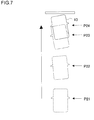
- FIG. 7 is a view schematically illustrating the vehicle 10 to be stopped in an unstable state of the behavior thereof.
- the engine stop control unit 40 determines to avoid stopping the engine 50 regardless of whether the other automatic stop conditions are satisfied. Accordingly, the engine stop control unit 40 continues the operation of the engine 50 even when the vehicle 10 proceeds to the third position P23 being a position just before stopping and proceeds to the fourth position P24 being a stop position.
- the engine stop control unit 40 avoids stopping the engine 50 even when the vehicle 10 is decelerated to or lower than the specified vehicle speed.
- the vehicle 10 is provided with an EPS to assist steering force of the driver. With the above configuration, appropriate steering assistance by the EPS can be continued.
- FIG. 8 is a flowchart which describes detailed procedure of the automatic start determination process of S14 in FIG. 2 .
- the engine 50 is started in the case of satisfying either of normal automatic start conditions or emergency automatic start conditions which are the automatic start conditions for automatically starting the engine 50.
- the engine start control unit 42 determines whether the normal automatic start conditions are satisfied (S50).
- the normal automatic start conditions include conditions in which the possibility to start the vehicle 10 is determined to be high, such as detection of depression releasing of a brake pedal and detection of shifting of a shift lever from a neutral (N) position to a drive (D) position. Since such normal automatic start conditions are known to the public, the description thereof will not be described.
- the engine start control unit 42 starts the engine 50 (S52).
- the engine start control unit 42 determines whether the emergency automatic start conditions are satisfied. Specifically, first, the engine start control unit 42 determines whether the behavior of the vehicle 10 is in an unstable state (S54). When the behavior of the vehicle 10 in is a stable state ("N" in S54), the engine start control unit 42 determines that it is not necessary to urgently start the engine 50. Accordingly, the engine start control unit 42 avoids starting the engine 50 as the automatic start conditions are not satisfied and maintains the stopped state of the engine 50 (S62). When the behavior of the vehicle 10 is in an unstable state ("Y" in S54), the engine start control unit 42 determines whether the unstable tendency of the vehicle 10 is being increased (S56).
- FIG. 9 is a table indicating the determination criteria whether the behavior of the vehicle 10 is in a stable state.
- the behavior determination unit 44 determines that the behavior of the vehicle 10 is in a stable state.
- the behavior determination unit 44 determines the behavior of the vehicle 10 to be in an unstable state.
- the behavior determination unit 44 determines the behavior of the vehicle 10 to be in a stable state. That is, the yaw rate detected by the yaw rate sensor 34 is smaller than a specified value C1, a yaw rate variation amount compared to the previous detection value detected by the yaw rate sensor 34 is smaller than a specified value C2, lateral acceleration detected by the lateral acceleration sensor 32 is smaller than a specified value C3, and a lateral acceleration variation amount compared to the previous detection value detected by the lateral acceleration sensor 32 is smaller than a specified value C4.
- the specified values C1 to C4 are set to be different from the above specified values A1 to A4. However, one or more of the specified values C1 to C4 may be the same value as the specified values A1 to A4.
- FIG. 10 is a table indicating the determination criteria whether the unstable tendency of the vehicle 10 is being increased.
- the behavior determination unit 44 determines that the unstable tendency of the vehicle 10 is being increased. Specifically, when the yaw rate detected by the yaw rate sensor 34 is increased compared to the previous value or when the lateral acceleration detected by the lateral acceleration sensor 32 is increased compared to the previous value, the behavior determination unit 44 determines that the unstable tendency of the vehicle 10 is being increased.
- the engine start control unit 42 starts the engine 50 (S52).
- the engine start control unit 42 determines whether the steering force assistance is being performed by the EPS (S58). When the steering force assistance is not being performed (“N” in S58), the engine start control unit 42 starts the engine 50 (S52).
- the engine start control unit 42 determines whether other emergency automatic start conditions are satisfied (S60). When the other emergency automatic start conditions are satisfied ("Y" in S60), the engine start control unit 42 starts the engine 50 (S52). When the other emergency automatic start conditions are not satisfied (“N” in S60), the engine start control unit 42 avoids starting the engine 50 and maintains the stopped state of the engine 50 (S62).
- the engine start control unit 42 starts the engine 50 as the automatic start conditions are satisfied.
- the engine start control unit 42 avoids starting the engine 50 as the automatic start conditions are not satisfied.
- FIG. 11 is a table indicating the other emergency automatic start conditions.
- the engine start control unit 42 determines that the other emergency automatic start conditions are satisfied. Specifically, when the remaining amount of power is equal to or smaller than a specified value D1 or the remaining amount of the brake negative pressure is equal to or smaller than a specified value D2, the engine start control unit 42 determines that the other emergency automatic start conditions are satisfied.
- FIG. 12 is a view schematically illustrating the vehicle 10 of which behavior becomes unstable due to slipping down from a stopped state.
- the vehicle 10 has been stopped on a low- ⁇ uphill road such as an ice-covered road at the first position P31.
- a low- ⁇ inclined road there is a possibility that the vehicle slips down while the wheels are locked.
- the behavior of the vehicle 10 is determined to be in an unstable state at the second position P32 while the value satisfying the conditions in FIG. 9 is detected by the yaw rate sensor 34 or the lateral acceleration sensor 32 even though the wheel speed of each of four wheels is zero.
- the engine start control unit 42 avoids starting the engine 50 in order to avoid unusual steering feeling due to power consumption required for starting the engine 50.
- the engine start control unit 42 starts the engine 50.
- the present invention is not limited to the above embodiment. Appropriate combination of each configuration of the present embodiment is also effective as an embodiment of the present invention. In addition, it is also possible to apply modification such as various design changes to the present embodiment based on knowledge of skilled persons. The embodiment to which such a modification is applied may be included in the scope of the present invention.
- the present invention in a vehicle having an engine capable of being automatically stopped or started, it is possible to provide a state capable of appropriately supplying power to equipment which requires power even when a vehicle behavior is unstable.
Landscapes
- Engineering & Computer Science (AREA)
- Chemical & Material Sciences (AREA)
- Combustion & Propulsion (AREA)
- Mechanical Engineering (AREA)
- Transportation (AREA)
- General Engineering & Computer Science (AREA)
- Automation & Control Theory (AREA)
- Control Of Vehicle Engines Or Engines For Specific Uses (AREA)
- Hybrid Electric Vehicles (AREA)
Abstract
Description
- The present invention relates to a vehicle drive control apparatus, in particular, relates to a vehicle drive control apparatus to automatically stop or start an engine thereof.
- In these days of the increasingly important environmental issue, suppressing greenhouse effect gas exhausted from vehicles has been strongly desired. Recently, development of technology to suppress idling operation by automatically stopping an engine during vehicle stopping has been widely performed.
- Following are examples of such technologies. A control apparatus for a hybrid vehicle to automatically restart an engine when amount of battery charge falls below a specified value during engine stopping has been proposed (see Patent Document 1, for example). Further, a technology to store behavior-related information at a storage portion along with map information when certain vehicle behavior is detected at some point and to reflect on vehicle control for passing through the same point through the same route has been proposed (see Patent Document 2, for example). Further, a technology to prohibit automatic starting of an engine as occurrence of vehicle collision being determined when the vehicle detects an impact of a specified value or higher has been proposed (see Patent Document 3, for example). Further, a technology to prohibit automatic starting of an engine during parking operation has been proposed (see Patent Document 4, for example). Further, a technology to forcedly start an internal combustion engine when negative pressure is not sufficiently ensured necessary for generating minimum desired assistance force by a brake booster has been proposed (see Patent Document 5, for example). Furthermore, a technology to prohibit automatic stopping of an engine, even if automatic stop conditions of the engine are established, when locking of a drive wheel is detected due to operation of an antilocked braking system (ABS) and the like has been proposed (see Paten Document 6, for example).
-
- [Patent Document 1] Japanese Patent Application Laid-open No.
2004-166389 - [Patent Document 2] Japanese Patent Application Laid-open No.
2002-219957 - [Patent Document 3] Japanese Patent Application Laid-open No.
2003-138955 - [Patent Document 4] Japanese Patent Application Laid-open No.
2008-510926 - [Patent Document 5] Japanese Patent Application Laid-open No.
2001-012272 - [Patent Document 6] Japanese Patent Application Laid-open No.
2001-032734 - For example, on a low-µ road such as an ice-covered road, there is a possibility that a behavior becomes unstable such that a vehicle moves in the lateral direction when the vehicle is about to be stopped or stopped at an inclined road. In such a state of an unstable behavior, there is a high possibility that steering is performed by a driver in order to correct a vehicle attitude. Presently, an electric power steering (EPS) is widely adopted for a number of vehicles. In the vehicle being provided with an EPS, large power is consumed when the driver steers a steering wheel in order to turn the vehicle at an extremely low speed or during stopping. Accordingly, when the engine is stopped for idling stop and the like in the state that a vehicle behavior becomes unstable as mentioned above, it becomes difficult to quickly charge power consumed by the EPS and the like.
- To address the above issue, the present invention is devised to provide a state capable of appropriately supplying power to equipment which requires power even when a vehicle behavior is unstable in a vehicle having an engine capable of being automatically stopped or started.
- In view of the above issue, a vehicle drive control apparatus includes an engine stop control unit which stops an engine when an automatic stop condition for automatically stopping the engine is satisfied during operation of the engine and a behavior determination unit which determines whether a behavior of a vehicle is a stable state or an unstable state. The engine stop control unit avoids stopping the engine as the automatic stop condition is not satisfied when the behavior of the vehicle is determined to be an unstable state during operation of the engine.
- According to an aspect, a state capable of appropriately supplying power to equipment which requires power can be obtained by avoiding stopping of an engine when a vehicle behavior is unstable.
- The behavior determination unit may determine whether the behavior of the vehicle is a stable state or an unstable state based on a turning behavior of the vehicle.
- On a low-µ road as mentioned above, a vehicle is apt to be into a behavior unstable state of lateral moving. Such an unstable state of the vehicle due to lateral moving thereof is possible to be appropriately determined by utilizing a turning behavior of the vehicle. Therefore, according to the aspect, an unstable state of such behavior can be appropriately determined.
- Here, a vehicle behavior control unit which controls a vehicle behavior may be further provided. The engine stop control unit may avoid stopping the engine during vehicle behavior control performed by the vehicle behavior control unit as the automatic stop condition is not satisfied.
- When behavior control such as ABS and stability control is performed, there is a high possibility that a vehicle behavior is shifted from an unstable state to a stable state. Therefore, according to the aspect, frequency of avoiding automatic stopping of an engine caused by a vehicle being an unstable state can be suppressed. Accordingly, an engine can be automatically stopped appropriately, so that idling operation can be suppressed.
- The engine stop control unit may stop the engine in the case that the vehicle is decelerated to or lower than a specified vehicle speed at which the engine is to be automatically stopped and that the behavior of the vehicle is determined to be a stable state, and may avoid stopping the engine in the case that the behavior of the vehicle is determined to be in an unstable state even when the vehicle is decelerated to or lower than the specified vehicle speed.
- When braking force is applied to wheels so as to decelerate a vehicle on a low-µ road, for example, a vehicle behavior is apt to fall in an unstable state. According to the aspect, automatic stopping of an engine can be appropriately avoided in such a case.
- According to another aspect of the present invention, there is also provided a vehicle drive control apparatus. The apparatus includes an engine start control unit which starts an engine when an automatic start condition for automatically starting the engine is satisfied during stopping of the engine and a behavior determination unit which determines whether a behavior of a vehicle is in a stable state or an unstable state. The engine start control unit starts the engine as the automatic start condition is satisfied when the behavior of the vehicle is determined to be in an unstable state during stopping of the engine.
- When a vehicle is stopped on a low-µ inclined road, for example, there may be a case that the vehicle gradually slips down. When a vehicle behavior becomes unstable as mentioned above, there is a high possibility that control requiring power, such as EPS operation caused by driver's steering operation of a steering wheel, is performed. According to the aspect, by starting an engine when a vehicle behavior is in an unstable state as mentioned above, power can be appropriately supplied to equipment which requires power in a vehicle.
- The behavior determination unit may determine whether the behavior of the vehicle is in a stable state or an unstable state based on a turning behavior of the vehicle.
- When a vehicle slips down on a low-µ inclined road, a turning behavior of the vehicle is to be detected. Therefore, according to the aspect, a vehicle behavior can be appropriately determined whether to be in a stable state or to be in an unstable state.
- Here, a steering assistance unit which assists steering force may be further provided. The engine start control unit may avoid starting the engine as the automatic start condition is not satisfied when steering force is assisted by the steering assistance unit even if the behavior of the vehicle is determined to be in an unstable state.
- For example, when slipping down speed of a vehicle is gradually increasing, there is a high possibility that control requiring power, such as EPS operation caused by driver' s steering operation of a steering wheel, is immediately performed. Here, in order to start an engine, relatively large power is necessary even in a fraction of a second. Therefore, when the engine is started during the EPS operation, unusual feeling can be provided to the driver during steering operation due to assistance force fluctuation of the EPS. According to the aspect, such unusual feeling can be suppressed so that an influence thereof to driver' s steering feeling can be avoided.
- According to the present invention, in a vehicle having an engine capable of being automatically stopped or started, it is possible to provide a state capable of appropriately supplying power to equipment which requires power even when a vehicle behavior is unstable.
-
FIG. 1 is a functional block diagram schematically illustrating the configuration of a vehicle drive control apparatus mounted on a vehicle according to the first embodiment; -
FIG. 2 is a flowchart illustrating procedure of an automatic stop/start process by the vehicle drive control apparatus; -
FIG. 3 is a flowchart illustrating detailed procedure of an automatic stop determination process of S12 inFIG. 2 ; -
FIG. 4 is a table indicating determination criteria whether a vehicle behavior is in a stable state; -
FIG. 5 is a table indicating other automatic stop conditions; -
FIG. 6 is a view schematically illustrating the vehicle to be stopped while the behavior thereof remains in a stable state; -
FIG. 7 is a view schematically illustrating the vehicle to be stopped in an unstable state of the behavior thereof; -
FIG. 8 is a flowchart illustrating detailed procedure of an automatic start determination process of S14 inFIG. 2 ; -
FIG. 9 is a table indicating determination criteria whether the vehicle behavior is in a stable state; -
FIG. 10 is a table indicating determination criteria whether an unstable tendency of the vehicle is being increased; -
FIG. 11 is a table indicating other emergency automatic start conditions; and -
FIG. 12 is a view schematically illustrating the vehicle of which behavior becomes unstable due to slipping down from a stopped state. - In the following, embodiment of the present invention (hereinafter called the present embodiment) will be described in detail with reference to the drawings.
-
FIG. 1 is a functional block diagram schematically illustrating the configuration of a vehicledrive control apparatus 20 mounted on avehicle 10 according to the first embodiment. The vehicledrive control apparatus 20 has an eco-run electronic control unit 24 (hereinafter, an electronic control unit is abbreviated to an ECU). Theeco-run ECU 24 is connected to astability ECU 22 and anengine ECU 26. - Each of the
stability ECU 22, theeco-run ECU 24 and theengine ECU 26 includes a CPU to perform a variety of arithmetic processes, a ROM to store a variety of control programs, and a RAM to be utilized as a work area for data storing and program performing. InFIG. 1 , theeco-run ECU 24 is illustrated with functional blocks which are performed in liaison of software and hardware such as the CPU, ROM and RAM. Accordingly, these functional blocks may be performed in a variety of manners by combinations of the software and hardware. - The
vehicle 10 is provided with awheel speed sensor 30, alateral acceleration sensor 32 and ayaw rate sensor 34. Thewheel speed sensor 30 is arranged corresponding to each of four wheels (not illustrated) disposed at thevehicle 10 so as to detect rotation speed of the corresponding wheel. Thelateral acceleration sensor 32 detects acceleration applied to thevehicle 10 in the vehicle width direction. Theyaw rate sensor 34 detects a yaw rate of thevehicle 10. - The
stability ECU 22 is connected to thewheel speed sensor 30, thelateral acceleration sensor 32 and theyaw rate sensor 34 so as to obtain detection results respectively therefrom. Thestability ECU 22 performs behavior stabilization control to stabilize a behavior of thevehicle 10 by utilizing the obtained detection results. Since such behavior stabilization control is known to the public, the description thereof is skipped. - The
vehicle 10 is provided with anengine 50 of internal combustion as a drive source. Theengine ECU 26 performs controlling start and stop of theengine 50 as well as controlling opening of a throttle valve and fuel injection amount by an injector which are disposed at theengine 50. Here, for example, instead of theengine 50, an electric motor and the like may be adopted as the drive source of thevehicle 10. Thevehicle 10 may be a so-called hybrid vehicle which is driven in collaboration of theengine 50 and an electric motor. - The
eco-run ECU 24 performs control to automatically stop or start theengine 50 for stopping idling operation during stopping of thevehicle 10 or the like. Theeco-run ECU 24 includes an enginestop control unit 40, an enginestart control unit 42 and abehavior determination unit 44. - The
eco-run ECU 24 possesses automatic stop conditions for automatically stopping theengine 50 and automatic start conditions for automatically starting theengine 50. The enginestop control unit 40 stops theengine 50 when the automatic stop conditions are satisfied during operation of theengine 50. The enginestart control unit 42 starts theengine 50 when the automatic start conditions are satisfied during stopping of theengine 50. - The
behavior determination unit 44 determines whether a behavior of thevehicle 10 is in a stable state or an unstable state. Specifically, thebehavior determination unit 44 obtains detection results of thewheel speed sensor 30, thelateral acceleration sensor 32 and theyaw rate sensor 34 via thestability ECU 22. Then, thebehavior determination unit 44 determines whether the behavior of thevehicle 10 is in a stable state or an unstable state based on these detection results regarding a turning behavior of thevehicle 10. Specific criteria for the determination will be described below. -
FIG. 2 is a flowchart illustrating procedure of an automatic stop/start process by the vehicledrive control apparatus 20. The process in this flowchart is started when an ignition switch of thevehicle 10 is turned on and repeatedly performed every predetermined time thereafter. - The
eco-run ECU 24 determines whether theengine 50 is in operation (S10). When theengine 50 is determined to be in operation ("Y" in S10), the enginestop control unit 40 performs an automatic stop determination process (S12). When theengine 50 is determined not to be in operation ("N" in S10), the enginestart control unit 42 performs an automatic start determination process (S14). -
FIG. 3 is a flowchart illustrating detailed procedure of the automatic stop determination process of S12 inFIG. 2 . When the automatic stop conditions for theengine 50 to be automatically stopped is satisfied, the enginestop control unit 40 stops theengine 50. When the conditions are not satisfied, the enginestop control unit 40 avoids stopping theengine 50 and continues the operation of theengine 50. In the present embodiment, the automatic stop conditions include the state that the behavior of thevehicle 10 is stable. - Accordingly, the
behavior determination unit 44 determines whether the behavior of thevehicle 10 is in a stable state or an unstable state by utilizing the detection results of thelateral acceleration sensor 32 and the yaw rate sensor 34 (S30). When the behavior of thevehicle 10 is in an unstable state ("N" in S30), the enginestop control unit 40 avoids stopping theengine 50 and continues the operation of theengine 50 due to determination that the automatic stop conditions are not satisfied regardless of satisfaction of other automatic stop conditions. (S36). - When the behavior of the
vehicle 10 is in a stable state ("Y" in S30), the enginestop control unit 40 determines whether the other automatic stop conditions are satisfied (S32). In the case of being satisfied ("Y" in S32), the enginestop control unit 40 stops the engine 50 (S34). In the case of not being satisfied ("N" in S32), the enginestop control unit 40 avoids stopping theengine 50 and continues the operation of the engine 50 (S36). -
FIG. 4 is a table indicating the determination criteria whether the behavior of thevehicle 10 is in a stable state. When all of the conditions listed on respective rows of this table are satisfied, thebehavior determination unit 44 determines the behavior of thevehicle 10 to be in a stable state. On the contrary, when any of the conditions listed on the respective rows of this table is not satisfied, thebehavior determination unit 44 determines the behavior of thevehicle 10 to be in an unstable state. - Specifically, when all of the following conditions are satisfied, the
behavior determination unit 44 determines the behavior of thevehicle 10 to be in a stable state. That is, the yaw rate detected by theyaw rate sensor 34 is smaller than a specified value A1, a yaw rate variation amount compared to the previous detection value detected by theyaw rate sensor 34 is smaller than a specified value A2, lateral acceleration detected by thelateral acceleration sensor 32 is smaller than a specified value A3, and a lateral acceleration variation amount compared to the previous detection value detected by thelateral acceleration sensor 32 is smaller than a specified value A4. -
FIG. 5 is a table indicating the other automatic stop conditions inFIG. 3 . When all of the conditions listed on respective rows of this table are satisfied, the enginestop control unit 40 determines that the other automatic stop conditions are satisfied. Specifically, thevehicle 10 includes a stop switch (not illustrated), a brake negative pressure sensor (not illustrated), a battery (not illustrated) and an ABS-ECU (not illustrated). - The stop switch is turned on when a brake pedal is depressed by a driver. The brake negative pressure sensor detects brake negative pressure to assist depressing force of the brake pedal. The
eco-run ECU 24 obtains a signal indicating on-off of the stop switch and a detected signal of the brake negative pressure. The battery is connected to theeco-run ECU 24 as well and theeco-run ECU 24 monitors a remaining power amount of the battery at predetermined intervals. The ABS-ECU controls braking force applied to the wheels to avoid wheel locking. Theeco-run ECU 24 is arranged to be capable of determining whether the ABS control is being performed by referring to a control flag and the like at the ABS-ECU. - When all of the following conditions are satisfied, the engine
stop control unit 40 determines that the other automatic stop conditions are satisfied. That is, the maximum wheel speed among the four wheels is lower than a specified value B1, the stop switch is ON, the remaining amount of power is larger than a specified value B2, the remaining amount of the brake negative pressure is larger than a specified value B3, the ABS control is not in operation, and the stability control is not in operation. Accordingly, when the ABS control or the stability control being behavior control of thevehicle 10 is being performed by thestability ECU 22, thebehavior determination unit 44 does not determine the behavior of thevehicle 10 to be in an unstable state. - Returning to
FIG. 3 , when the other automatic stop conditions are satisfied ("Y" in S32), the enginestop control unit 40 stops the engine 50 (S34). When the behavior of thevehicle 10 is not in a stable state ("N" in S30), the enginestop control unit 40 avoids stopping theengine 50 and continues the operation of the engine 50 (S36). When the other automatic stop conditions are not satisfied ("N" in S32), the engine stop control unit 40 a avoids stopping theengine 50 and continues the operation of the engine 50 (S36). -
FIG. 6 is a view schematically illustrating thevehicle 10 to be stopped while the behavior thereof remains in a stable state. For example, in the case that a brake pedal is depressed by a driver at the first position P11 and the determination is performed at the second position P12 as the behavior of thevehicle 10 is in a stable state and the other automatic stop conditions are satisfied, the enginestop control unit 40 determines to stop theengine 50. The enginestop control unit 40 provides a signal of instructing to stop theengine 50 to theengine ECU 26. Theengine ECU 26 stops theengine 50 at the third position P13 where thevehicle 10 is not completely stopped yet. Subsequently, thevehicle 10 is stopped at the fourth position P14. - As described above, in the case that the
vehicle 10 is decelerated to or lower than a specified vehicle speed for automatically stopping theengine 50 and that the behavior of thevehicle 10 is determined to be in a stable state, the enginestop control unit 40 stops theengine 50. Accordingly, when the behavior of thevehicle 10 is stable, theengine 50 can be stopped before thevehicle 10 is stopped. Hence, it is possible to stop theengine 50 more quickly. -
FIG. 7 is a view schematically illustrating thevehicle 10 to be stopped in an unstable state of the behavior thereof. For example, in the case that the brake pedal is depressed by the driver at the first position P21 and the behavior of thevehicle 10 is determined to be in an unstable state at the second position P22, the enginestop control unit 40 determines to avoid stopping theengine 50 regardless of whether the other automatic stop conditions are satisfied. Accordingly, the enginestop control unit 40 continues the operation of theengine 50 even when thevehicle 10 proceeds to the third position P23 being a position just before stopping and proceeds to the fourth position P24 being a stop position. - In this manner, in the case that the behavior of the
vehicle 10 is determined to be in an unstable state, the enginestop control unit 40 avoids stopping theengine 50 even when thevehicle 10 is decelerated to or lower than the specified vehicle speed. Here, thevehicle 10 is provided with an EPS to assist steering force of the driver. With the above configuration, appropriate steering assistance by the EPS can be continued. -
FIG. 8 is a flowchart which describes detailed procedure of the automatic start determination process of S14 inFIG. 2 . In the automatic start determination process, theengine 50 is started in the case of satisfying either of normal automatic start conditions or emergency automatic start conditions which are the automatic start conditions for automatically starting theengine 50. - Specifically, the engine
start control unit 42 determines whether the normal automatic start conditions are satisfied (S50). The normal automatic start conditions include conditions in which the possibility to start thevehicle 10 is determined to be high, such as detection of depression releasing of a brake pedal and detection of shifting of a shift lever from a neutral (N) position to a drive (D) position. Since such normal automatic start conditions are known to the public, the description thereof will not be described. When the normal automatic start conditions are satisfied ("Y" in S50), the enginestart control unit 42 starts the engine 50 (S52). - When the normal automatic start conditions are not satisfied ("N" in S50), the engine
start control unit 42 determines whether the emergency automatic start conditions are satisfied. Specifically, first, the enginestart control unit 42 determines whether the behavior of thevehicle 10 is in an unstable state (S54). When the behavior of thevehicle 10 in is a stable state ("N" in S54), the enginestart control unit 42 determines that it is not necessary to urgently start theengine 50. Accordingly, the enginestart control unit 42 avoids starting theengine 50 as the automatic start conditions are not satisfied and maintains the stopped state of the engine 50 (S62). When the behavior of thevehicle 10 is in an unstable state ("Y" in S54), the enginestart control unit 42 determines whether the unstable tendency of thevehicle 10 is being increased (S56). -
FIG. 9 is a table indicating the determination criteria whether the behavior of thevehicle 10 is in a stable state. In the case that all of the conditions listed on respective rows of this table are satisfied while the wheel speed of each of four wheels is zero, thebehavior determination unit 44 determines that the behavior of thevehicle 10 is in a stable state. On the contrary, in the case that any of the conditions listed on the respective rows of this table is not satisfied even though the wheel speed of each of the four wheels is zero, there may be a possibility that thevehicle 10 is slipping down on a low-µ inclined road. Therefore, in this case, thebehavior determination unit 44 determines the behavior of thevehicle 10 to be in an unstable state. - Specifically, when all of the following conditions are satisfied, the
behavior determination unit 44 determines the behavior of thevehicle 10 to be in a stable state. That is, the yaw rate detected by theyaw rate sensor 34 is smaller than a specified value C1, a yaw rate variation amount compared to the previous detection value detected by theyaw rate sensor 34 is smaller than a specified value C2, lateral acceleration detected by thelateral acceleration sensor 32 is smaller than a specified value C3, and a lateral acceleration variation amount compared to the previous detection value detected by thelateral acceleration sensor 32 is smaller than a specified value C4. Here, the specified values C1 to C4 are set to be different from the above specified values A1 to A4. However, one or more of the specified values C1 to C4 may be the same value as the specified values A1 to A4. -
FIG. 10 is a table indicating the determination criteria whether the unstable tendency of thevehicle 10 is being increased. When any of the conditions listed on respective rows of this table is satisfied, thebehavior determination unit 44 determines that the unstable tendency of thevehicle 10 is being increased. Specifically, when the yaw rate detected by theyaw rate sensor 34 is increased compared to the previous value or when the lateral acceleration detected by thelateral acceleration sensor 32 is increased compared to the previous value, thebehavior determination unit 44 determines that the unstable tendency of thevehicle 10 is being increased. - Returning to
FIG. 8 , when the unstable tendency of thevehicle 10 is not being increased ("N" in S56), the enginestart control unit 42 starts the engine 50 (S52). When the unstable tendency of thevehicle 10 is being increased ("Y" in S56), the enginestart control unit 42 determines whether the steering force assistance is being performed by the EPS (S58). When the steering force assistance is not being performed ("N" in S58), the enginestart control unit 42 starts the engine 50 (S52). - When the steering force assistance is being performed ("Y" in S58), the engine
start control unit 42 determines whether other emergency automatic start conditions are satisfied (S60). When the other emergency automatic start conditions are satisfied ("Y" in S60), the enginestart control unit 42 starts the engine 50 (S52). When the other emergency automatic start conditions are not satisfied ("N" in S60), the enginestart control unit 42 avoids starting theengine 50 and maintains the stopped state of the engine 50 (S62). - In this manner, in the case that the behavior of the
vehicle 10 is determined to be in an unstable state during stopping of theengine 50, the enginestart control unit 42 starts theengine 50 as the automatic start conditions are satisfied. On the other hand, in the case that the steering force is assisted by the EPS even though the behavior of thevehicle 10 is determined to be in an unstable state, the enginestart control unit 42 avoids starting theengine 50 as the automatic start conditions are not satisfied. -
FIG. 11 is a table indicating the other emergency automatic start conditions. When any of the conditions listed on respective rows of this table is satisfied, the enginestart control unit 42 determines that the other emergency automatic start conditions are satisfied. Specifically, when the remaining amount of power is equal to or smaller than a specified value D1 or the remaining amount of the brake negative pressure is equal to or smaller than a specified value D2, the enginestart control unit 42 determines that the other emergency automatic start conditions are satisfied. -
FIG. 12 is a view schematically illustrating thevehicle 10 of which behavior becomes unstable due to slipping down from a stopped state. InFIG. 12 , it is assumed that thevehicle 10 has been stopped on a low-µ uphill road such as an ice-covered road at the first position P31. On a low-µ inclined road, there is a possibility that the vehicle slips down while the wheels are locked. - For example, it is assumed that the behavior of the
vehicle 10 is determined to be in an unstable state at the second position P32 while the value satisfying the conditions inFIG. 9 is detected by theyaw rate sensor 34 or thelateral acceleration sensor 32 even though the wheel speed of each of four wheels is zero. In the case that the driver who feels an unstable behavior state steers a wheel steering to cause the operational force assistance of the EPS performed in order to correct an attitude of thevehicle 10, the enginestart control unit 42 avoids starting theengine 50 in order to avoid unusual steering feeling due to power consumption required for starting theengine 50. After the attitude of thevehicle 10 is corrected at the third position P33 and operational force assistance by the EPS is completed due to completion of the wheel steering operation by the driver, the enginestart control unit 42 starts theengine 50. - The present invention is not limited to the above embodiment. Appropriate combination of each configuration of the present embodiment is also effective as an embodiment of the present invention. In addition, it is also possible to apply modification such as various design changes to the present embodiment based on knowledge of skilled persons. The embodiment to which such a modification is applied may be included in the scope of the present invention.
-
- 10 Vehicle
- 20 Vehicle drive control apparatus
- 22 Stability ECU
- 24 Eco-run ECU
- 26 Engine ECU
- 30 Wheel speed sensor
- 32 Lateral acceleration sensor
- 34 Yaw rate sensor
- 40 Engine stop control unit
- 42 Engine start control unit
- 44 Behavior determination unit
- 50 Engine
- According to the present invention, in a vehicle having an engine capable of being automatically stopped or started, it is possible to provide a state capable of appropriately supplying power to equipment which requires power even when a vehicle behavior is unstable.
Claims (7)
- A vehicle drive control apparatus comprising
an engine stop control unit which stops an engine when an automatic stop condition for automatically stopping the engine is satisfied during operation of the engine, and
a behavior determination unit which determines whether a behavior of a vehicle is in a stable state or an unstable state,
wherein
the engine stop control unit avoids stopping the engine as the automatic stop condition is not satisfied when the behavior of the vehicle is determined to be in an unstable state during operation of the engine. - The vehicle drive control apparatus according to claim 1, wherein
the behavior determination unit determines whether the behavior of the vehicle is in a stable state or an unstable state based on a turning behavior of the vehicle. - The vehicle drive control apparatus according to claim 1, further comprising a vehicle behavior control unit which controls vehicle behavior, wherein
the engine stop control unit avoids stopping the engine during vehicle behavior control performed by the vehicle behavior control unit as the automatic stop condition is not satisfied. - The vehicle drive control apparatus according to any one of claims 1 to 3 wherein
the engine stop control unit stops the engine in a case that the vehicle is decelerated to or lower than a specified vehicle speed at which the engine is to be automatically stopped and that the behavior of the vehicle is determined to be in a stable state, and
the engine stop control unit avoids stopping the engine in a case that the behavior of the vehicle is determined to be in an unstable state even when the vehicle is decelerated to or lower than the specified vehicle speed. - A vehicle drive control apparatus comprising:an engine start control unit which starts an engine when an automatic start condition for automatically starting the engine is satisfied during stopping of the engine; anda behavior determination unit which determines whether a behavior of a vehicle is in a stable state or an unstable state,wherein
the engine start control unit starts the engine as the automatic start condition is satisfied when the behavior of the vehicle is determined to be in an unstable state during stopping of the engine. - The vehicle drive control apparatus according to claim 5, wherein
the behavior determination unit determines whether the behavior of the vehicle is in a stable state or an unstable state based on a turning behavior of the vehicle. - The vehicle drive control apparatus according to claim 5, further comprising a steering assistance unit which assists steering force, wherein
the engine start control unit avoids starting the engine as the automatic start condition is not satisfied during steering force is assisted by the steering assistance unit even when the behavior of the vehicle is determined to be in an unstable state.
Applications Claiming Priority (1)
| Application Number | Priority Date | Filing Date | Title |
|---|---|---|---|
| PCT/JP2009/002029 WO2010128539A1 (en) | 2009-05-08 | 2009-05-08 | Vehicle drive control device |
Publications (3)
| Publication Number | Publication Date |
|---|---|
| EP2428667A1 true EP2428667A1 (en) | 2012-03-14 |
| EP2428667A4 EP2428667A4 (en) | 2014-07-09 |
| EP2428667B1 EP2428667B1 (en) | 2020-04-08 |
Family
ID=43050052
Family Applications (1)
| Application Number | Title | Priority Date | Filing Date |
|---|---|---|---|
| EP09844326.0A Active EP2428667B1 (en) | 2009-05-08 | 2009-05-08 | Vehicle drive control device |
Country Status (5)
| Country | Link |
|---|---|
| US (1) | US8498802B2 (en) |
| EP (1) | EP2428667B1 (en) |
| JP (1) | JP4924757B2 (en) |
| CN (1) | CN102422001B (en) |
| WO (1) | WO2010128539A1 (en) |
Cited By (1)
| Publication number | Priority date | Publication date | Assignee | Title |
|---|---|---|---|---|
| EP2665921A1 (en) * | 2011-01-19 | 2013-11-27 | Daimler AG | Method for automatically stopping an internal combustion engine of a motor vehicle |
Families Citing this family (22)
| Publication number | Priority date | Publication date | Assignee | Title |
|---|---|---|---|---|
| CN102046945B (en) * | 2009-08-21 | 2013-10-16 | 丰田自动车株式会社 | engine control equipment |
| KR101199058B1 (en) | 2010-12-06 | 2012-11-07 | 기아자동차주식회사 | Idle stop and go system and method for controlling thereof |
| KR101693871B1 (en) | 2010-12-07 | 2017-01-09 | 현대자동차주식회사 | Device and Method for Controlling ISG Logic |
| KR101189412B1 (en) * | 2010-12-07 | 2012-10-10 | 현대자동차주식회사 | Method and Device for Controlling ISG Logic |
| JP5573662B2 (en) * | 2010-12-24 | 2014-08-20 | トヨタ自動車株式会社 | Vehicle control device |
| KR101317138B1 (en) * | 2011-12-09 | 2013-10-18 | 기아자동차주식회사 | System And Method For Eco Driving Of Electric Vehicle |
| GB201201222D0 (en) * | 2012-01-25 | 2012-03-07 | Jaguar Cars | Motor vehicle and method of control of a motor vehicle |
| JP5974628B2 (en) * | 2012-05-21 | 2016-08-23 | スズキ株式会社 | Power steering control device |
| DE112012006826T5 (en) * | 2012-12-28 | 2015-05-21 | Toyota Jidosha Kabushiki Kaisha | Vehicle control unit |
| US9664136B2 (en) | 2013-03-11 | 2017-05-30 | Ford Global Technologies, Llc | Auto-stop control for a stop/start vehicle near water |
| US9243570B2 (en) | 2013-03-11 | 2016-01-26 | Ford Global Technologies, Llc | Auto-stop control for a stop/start vehicle at a service location |
| US10012202B2 (en) * | 2013-04-08 | 2018-07-03 | Honda Motor Co., Ltd. | Vehicular engine control device |
| DE102013218330B4 (en) * | 2013-09-12 | 2025-12-04 | Robert Bosch Gmbh | Method for operating a brake booster, control unit for carrying out the method and a braking system comprising the brake booster and the control unit |
| US9249742B2 (en) * | 2013-10-15 | 2016-02-02 | Ford Global Technologies, Llc | Vehicle auto-stop control in the vicinity of an emergency vehicle |
| EP2876016B1 (en) * | 2013-11-20 | 2020-09-02 | Nxp B.V. | Function monitor |
| JP6298008B2 (en) | 2015-04-24 | 2018-03-20 | トヨタ自動車株式会社 | Vehicle engine start control system |
| WO2017204805A1 (en) * | 2016-05-26 | 2017-11-30 | Cummins Inc. | Engine stop/start enablement based on combustion parameters |
| US10399554B2 (en) | 2017-07-19 | 2019-09-03 | Ford Global Technologies, Llc | Hybrid vehicle with auto stop start controllers |
| CN110228481B (en) * | 2018-03-06 | 2022-08-23 | 斑马智行网络(香港)有限公司 | Vehicle control method, device and equipment |
| KR102587244B1 (en) * | 2018-08-27 | 2023-10-06 | 현대자동차주식회사 | Method for autonomous vehicle of determining risk of collision |
| KR102881968B1 (en) * | 2020-12-08 | 2025-11-05 | 현대자동차주식회사 | Braking control method using predicted friction coeffieient of brake pad |
| GB2618548A (en) * | 2022-05-09 | 2023-11-15 | Jaguar Land Rover Ltd | Vehicle controller and control method |
Family Cites Families (41)
| Publication number | Priority date | Publication date | Assignee | Title |
|---|---|---|---|---|
| JPS5830438A (en) * | 1981-08-19 | 1983-02-22 | Nissan Motor Co Ltd | Fuel control apparatus for automobile engine |
| JPS5835245A (en) * | 1981-08-25 | 1983-03-01 | Toyota Motor Corp | Automatically stopping and restarting device of engine |
| JPH07468B2 (en) * | 1988-07-04 | 1995-01-11 | マツダ株式会社 | Rear wheel steering system |
| JP2981965B2 (en) * | 1993-11-29 | 1999-11-22 | 本田技研工業株式会社 | Vehicle driving force control device |
| AU690404B2 (en) * | 1994-12-27 | 1998-04-23 | Komatsu Limited | Device and method for limiting the vehicle speed of a working vehicle |
| JP3159147B2 (en) * | 1997-11-13 | 2001-04-23 | 株式会社豊田自動織機製作所 | Industrial vehicle body swing control device and industrial vehicle |
| US5948028A (en) * | 1998-02-03 | 1999-09-07 | Ford Global Technologies, Inc. | Method of improving response time in a vehicle active tilt control system |
| JP2000337190A (en) * | 1999-03-25 | 2000-12-05 | Toyota Motor Corp | Automatic engine stop control system for vehicles |
| JP2001012272A (en) | 1999-06-29 | 2001-01-16 | Toyota Motor Corp | Automatic stop / start device for internal combustion engine |
| JP3775117B2 (en) | 1999-07-23 | 2006-05-17 | 日産自動車株式会社 | Engine automatic stop vehicle |
| JP3463622B2 (en) * | 1999-09-14 | 2003-11-05 | トヨタ自動車株式会社 | Vehicle behavior control device |
| JP4051870B2 (en) * | 2000-09-05 | 2008-02-27 | スズキ株式会社 | Engine automatic stop / start control device |
| JP2002213269A (en) * | 2000-11-15 | 2002-07-31 | Toyota Motor Corp | Car |
| JP3736340B2 (en) * | 2000-12-14 | 2006-01-18 | トヨタ自動車株式会社 | Vehicle control device |
| JP3788736B2 (en) * | 2000-12-18 | 2006-06-21 | スズキ株式会社 | Engine automatic stop / start control device |
| JP2002219957A (en) | 2001-01-24 | 2002-08-06 | Nissan Motor Co Ltd | Vehicle control device |
| JP2002276447A (en) * | 2001-03-19 | 2002-09-25 | Denso Corp | Control device for internal combustion engine |
| US6558290B2 (en) * | 2001-06-29 | 2003-05-06 | Ford Global Technologies, Llc | Method for stopping an engine in a parallel hybrid electric vehicle |
| JP2003035177A (en) * | 2001-07-26 | 2003-02-07 | Denso Corp | Stop and restart device for engine vehicles |
| JP3571014B2 (en) * | 2001-08-30 | 2004-09-29 | 本田技研工業株式会社 | Automatic stop / start control device for internal combustion engine |
| US6725135B2 (en) * | 2001-09-26 | 2004-04-20 | Stability Dynamics | Vehicle stability operator feedback system |
| JP2003138955A (en) | 2001-11-06 | 2003-05-14 | Denso Corp | Automatic starter for internal combustion engine |
| JP3760840B2 (en) * | 2001-11-09 | 2006-03-29 | 日産自動車株式会社 | Automatic engine stop / restart system for vehicles |
| JP4027706B2 (en) * | 2002-04-23 | 2007-12-26 | 本田技研工業株式会社 | Engine control device |
| JP4039184B2 (en) * | 2002-08-29 | 2008-01-30 | 株式会社アドヴィックス | Creep travel control device |
| JP3843934B2 (en) | 2002-11-13 | 2006-11-08 | 日産自動車株式会社 | Control device for hybrid vehicle |
| WO2004067949A1 (en) * | 2003-01-27 | 2004-08-12 | Toyota Jidosha Kabushiki Kaisha | Control apparatus of internal combustion engine |
| JP2005023887A (en) * | 2003-07-04 | 2005-01-27 | Honda Motor Co Ltd | Control device for hybrid vehicle |
| JP2005271824A (en) * | 2004-03-25 | 2005-10-06 | Mitsubishi Fuso Truck & Bus Corp | Vehicular behavior control device |
| FR2874657B1 (en) | 2004-08-27 | 2009-10-09 | Peugeot Citroen Automobiles Sa | METHOD OF INHIBITING THE AUTOMATIC STOP CONTROL OF THE THERMAL MOTOR OF A VEHICLE DURING PARKING MANEUVERES |
| JP4385962B2 (en) * | 2004-09-14 | 2009-12-16 | トヨタ自動車株式会社 | Control device for internal combustion engine |
| FR2875550B1 (en) * | 2004-09-23 | 2006-12-22 | Valeo Equip Electr Moteur | METHOD FOR STOP CONTROL OF A VEHICLE |
| JP2006142994A (en) * | 2004-11-19 | 2006-06-08 | Denso Corp | VEHICLE NETWORK SYSTEM AND ELECTRONIC CONTROL DEVICE |
| JP4753604B2 (en) * | 2005-03-30 | 2011-08-24 | 富士通テン株式会社 | Eco-run system, eco-run control device, and navigation device |
| US7548805B2 (en) * | 2006-03-27 | 2009-06-16 | Fujitsu Ten Limited | Vehicle control apparatus, vehicle control method and vehicle slip suppressing apparatus |
| JP4640838B2 (en) * | 2006-07-11 | 2011-03-02 | 富士通テン株式会社 | Vehicle control device |
| EP2026988A2 (en) * | 2006-04-03 | 2009-02-25 | BluWav Systems, LLC | Vehicle power unit designed as retrofittable axle comprising motor, battery and suspension |
| JP4197013B2 (en) * | 2006-06-28 | 2008-12-17 | トヨタ自動車株式会社 | Control device for hybrid vehicle |
| US8131424B2 (en) * | 2008-01-16 | 2012-03-06 | GM Global Technology Operations LLC | Methods and systems for calculating yaw gain for use in controlling a vehicle |
| US8408177B2 (en) * | 2008-03-28 | 2013-04-02 | Mazda Motor Corporation | Control method for internal combustion engine system, and internal combustion engine system |
| JP4606488B2 (en) * | 2008-10-07 | 2011-01-05 | 三菱電機株式会社 | Control device for clutch |
-
2009
- 2009-05-08 WO PCT/JP2009/002029 patent/WO2010128539A1/en not_active Ceased
- 2009-05-08 CN CN200980159189.6A patent/CN102422001B/en active Active
- 2009-05-08 JP JP2010501312A patent/JP4924757B2/en active Active
- 2009-05-08 EP EP09844326.0A patent/EP2428667B1/en active Active
-
2010
- 2010-12-14 US US12/967,258 patent/US8498802B2/en active Active
Cited By (2)
| Publication number | Priority date | Publication date | Assignee | Title |
|---|---|---|---|---|
| EP2665921A1 (en) * | 2011-01-19 | 2013-11-27 | Daimler AG | Method for automatically stopping an internal combustion engine of a motor vehicle |
| DE102011009001B4 (en) | 2011-01-19 | 2018-05-30 | Werner Bernzen | Method for automatically stopping an internal combustion engine of a motor vehicle |
Also Published As
| Publication number | Publication date |
|---|---|
| EP2428667A4 (en) | 2014-07-09 |
| US20110082624A1 (en) | 2011-04-07 |
| WO2010128539A1 (en) | 2010-11-11 |
| CN102422001A (en) | 2012-04-18 |
| JPWO2010128539A1 (en) | 2012-11-01 |
| JP4924757B2 (en) | 2012-04-25 |
| US8498802B2 (en) | 2013-07-30 |
| EP2428667B1 (en) | 2020-04-08 |
| CN102422001B (en) | 2014-09-03 |
Similar Documents
| Publication | Publication Date | Title |
|---|---|---|
| EP2428667B1 (en) | Vehicle drive control device | |
| US9108623B2 (en) | System and method of controlling motor vehicle operation | |
| CN110154758B (en) | Driving assistance device | |
| US20110112740A1 (en) | Control device for internal combustion engine and method for controlling internal combustion engine | |
| US20110307152A1 (en) | Vehicle travel control device | |
| CN1332840C (en) | Roll-over suppressing control apparatus and method for a vehicle | |
| EP3418148B1 (en) | Vehicle behavior control device | |
| JP2011173586A (en) | Prevention device for runaway of automobile by wrong operation of accelerator | |
| US10569765B2 (en) | Vehicle behavior control device | |
| CN108974000B (en) | vehicle control device | |
| JP2006321268A (en) | Economic running control method and economic running controlling device | |
| JP5692500B2 (en) | Vehicle forward determination device | |
| JP2009275591A (en) | Vehicle controller | |
| JP2019048603A (en) | Automatic operation control device | |
| JP5924242B2 (en) | Idle stop control device and idle stop control method | |
| JP5938941B2 (en) | Vehicle control device | |
| JP5812853B2 (en) | Vehicle control device | |
| JP5018977B2 (en) | Automobile | |
| JP2018167719A (en) | Vehicle control device | |
| JP2009274701A (en) | Unit and method for vehicle motion control | |
| JP4752396B2 (en) | Car | |
| JP2011189758A (en) | Braking and driving force control apparatus | |
| JP2005168081A (en) | Driving force control device | |
| JP2018188085A (en) | Driving assistance device | |
| JP2008267587A (en) | Vehicle braking / driving force control apparatus and vehicle braking / driving force control method |
Legal Events
| Date | Code | Title | Description |
|---|---|---|---|
| PUAI | Public reference made under article 153(3) epc to a published international application that has entered the european phase |
Free format text: ORIGINAL CODE: 0009012 |
|
| 17P | Request for examination filed |
Effective date: 20111202 |
|
| AK | Designated contracting states |
Kind code of ref document: A1 Designated state(s): AT BE BG CH CY CZ DE DK EE ES FI FR GB GR HR HU IE IS IT LI LT LU LV MC MK MT NL NO PL PT RO SE SI SK TR |
|
| DAX | Request for extension of the european patent (deleted) | ||
| RAP1 | Party data changed (applicant data changed or rights of an application transferred) |
Owner name: TOYOTA JIDOSHA KABUSHIKI KAISHA |
|
| A4 | Supplementary search report drawn up and despatched |
Effective date: 20140610 |
|
| RIC1 | Information provided on ipc code assigned before grant |
Ipc: F02D 45/00 20060101ALI20140603BHEP Ipc: F02D 29/02 20060101AFI20140603BHEP Ipc: F02D 17/00 20060101ALI20140603BHEP Ipc: F02N 11/08 20060101ALI20140603BHEP |
|
| STAA | Information on the status of an ep patent application or granted ep patent |
Free format text: STATUS: EXAMINATION IS IN PROGRESS |
|
| 17Q | First examination report despatched |
Effective date: 20170522 |
|
| REG | Reference to a national code |
Ref country code: DE Ref legal event code: R079 Ref document number: 602009061702 Country of ref document: DE Free format text: PREVIOUS MAIN CLASS: F02D0029020000 Ipc: F02N0011080000 |
|
| RIC1 | Information provided on ipc code assigned before grant |
Ipc: B60W 10/06 20060101ALI20190730BHEP Ipc: F02N 11/08 20060101AFI20190730BHEP Ipc: B60W 10/20 20060101ALI20190730BHEP Ipc: B60W 30/18 20120101ALI20190730BHEP Ipc: F02N 11/10 20060101ALN20190730BHEP Ipc: F02D 29/02 20060101ALI20190730BHEP |
|
| GRAP | Despatch of communication of intention to grant a patent |
Free format text: ORIGINAL CODE: EPIDOSNIGR1 |
|
| STAA | Information on the status of an ep patent application or granted ep patent |
Free format text: STATUS: GRANT OF PATENT IS INTENDED |
|
| INTG | Intention to grant announced |
Effective date: 20190918 |
|
| GRAS | Grant fee paid |
Free format text: ORIGINAL CODE: EPIDOSNIGR3 |
|
| GRAA | (expected) grant |
Free format text: ORIGINAL CODE: 0009210 |
|
| STAA | Information on the status of an ep patent application or granted ep patent |
Free format text: STATUS: THE PATENT HAS BEEN GRANTED |
|
| RIN1 | Information on inventor provided before grant (corrected) |
Inventor name: YAMAMOTO, SHINSUKE |
|
| AK | Designated contracting states |
Kind code of ref document: B1 Designated state(s): AT BE BG CH CY CZ DE DK EE ES FI FR GB GR HR HU IE IS IT LI LT LU LV MC MK MT NL NO PL PT RO SE SI SK TR |
|
| REG | Reference to a national code |
Ref country code: GB Ref legal event code: FG4D |
|
| REG | Reference to a national code |
Ref country code: CH Ref legal event code: EP Ref country code: AT Ref legal event code: REF Ref document number: 1254721 Country of ref document: AT Kind code of ref document: T Effective date: 20200415 |
|
| REG | Reference to a national code |
Ref country code: IE Ref legal event code: FG4D |
|
| REG | Reference to a national code |
Ref country code: DE Ref legal event code: R096 Ref document number: 602009061702 Country of ref document: DE |
|
| REG | Reference to a national code |
Ref country code: NL Ref legal event code: MP Effective date: 20200408 |
|
| REG | Reference to a national code |
Ref country code: LT Ref legal event code: MG4D |
|
| PG25 | Lapsed in a contracting state [announced via postgrant information from national office to epo] |
Ref country code: NO Free format text: LAPSE BECAUSE OF FAILURE TO SUBMIT A TRANSLATION OF THE DESCRIPTION OR TO PAY THE FEE WITHIN THE PRESCRIBED TIME-LIMIT Effective date: 20200708 Ref country code: FI Free format text: LAPSE BECAUSE OF FAILURE TO SUBMIT A TRANSLATION OF THE DESCRIPTION OR TO PAY THE FEE WITHIN THE PRESCRIBED TIME-LIMIT Effective date: 20200408 Ref country code: GR Free format text: LAPSE BECAUSE OF FAILURE TO SUBMIT A TRANSLATION OF THE DESCRIPTION OR TO PAY THE FEE WITHIN THE PRESCRIBED TIME-LIMIT Effective date: 20200709 Ref country code: IS Free format text: LAPSE BECAUSE OF FAILURE TO SUBMIT A TRANSLATION OF THE DESCRIPTION OR TO PAY THE FEE WITHIN THE PRESCRIBED TIME-LIMIT Effective date: 20200808 Ref country code: SE Free format text: LAPSE BECAUSE OF FAILURE TO SUBMIT A TRANSLATION OF THE DESCRIPTION OR TO PAY THE FEE WITHIN THE PRESCRIBED TIME-LIMIT Effective date: 20200408 Ref country code: NL Free format text: LAPSE BECAUSE OF FAILURE TO SUBMIT A TRANSLATION OF THE DESCRIPTION OR TO PAY THE FEE WITHIN THE PRESCRIBED TIME-LIMIT Effective date: 20200408 Ref country code: LT Free format text: LAPSE BECAUSE OF FAILURE TO SUBMIT A TRANSLATION OF THE DESCRIPTION OR TO PAY THE FEE WITHIN THE PRESCRIBED TIME-LIMIT Effective date: 20200408 Ref country code: PT Free format text: LAPSE BECAUSE OF FAILURE TO SUBMIT A TRANSLATION OF THE DESCRIPTION OR TO PAY THE FEE WITHIN THE PRESCRIBED TIME-LIMIT Effective date: 20200817 |
|
| REG | Reference to a national code |
Ref country code: AT Ref legal event code: MK05 Ref document number: 1254721 Country of ref document: AT Kind code of ref document: T Effective date: 20200408 |
|
| PG25 | Lapsed in a contracting state [announced via postgrant information from national office to epo] |
Ref country code: BG Free format text: LAPSE BECAUSE OF FAILURE TO SUBMIT A TRANSLATION OF THE DESCRIPTION OR TO PAY THE FEE WITHIN THE PRESCRIBED TIME-LIMIT Effective date: 20200708 Ref country code: LV Free format text: LAPSE BECAUSE OF FAILURE TO SUBMIT A TRANSLATION OF THE DESCRIPTION OR TO PAY THE FEE WITHIN THE PRESCRIBED TIME-LIMIT Effective date: 20200408 Ref country code: HR Free format text: LAPSE BECAUSE OF FAILURE TO SUBMIT A TRANSLATION OF THE DESCRIPTION OR TO PAY THE FEE WITHIN THE PRESCRIBED TIME-LIMIT Effective date: 20200408 |
|
| REG | Reference to a national code |
Ref country code: DE Ref legal event code: R097 Ref document number: 602009061702 Country of ref document: DE |
|
| PG25 | Lapsed in a contracting state [announced via postgrant information from national office to epo] |
Ref country code: ES Free format text: LAPSE BECAUSE OF FAILURE TO SUBMIT A TRANSLATION OF THE DESCRIPTION OR TO PAY THE FEE WITHIN THE PRESCRIBED TIME-LIMIT Effective date: 20200408 Ref country code: MC Free format text: LAPSE BECAUSE OF FAILURE TO SUBMIT A TRANSLATION OF THE DESCRIPTION OR TO PAY THE FEE WITHIN THE PRESCRIBED TIME-LIMIT Effective date: 20200408 Ref country code: DK Free format text: LAPSE BECAUSE OF FAILURE TO SUBMIT A TRANSLATION OF THE DESCRIPTION OR TO PAY THE FEE WITHIN THE PRESCRIBED TIME-LIMIT Effective date: 20200408 Ref country code: LI Free format text: LAPSE BECAUSE OF NON-PAYMENT OF DUE FEES Effective date: 20200531 Ref country code: IT Free format text: LAPSE BECAUSE OF FAILURE TO SUBMIT A TRANSLATION OF THE DESCRIPTION OR TO PAY THE FEE WITHIN THE PRESCRIBED TIME-LIMIT Effective date: 20200408 Ref country code: AT Free format text: LAPSE BECAUSE OF FAILURE TO SUBMIT A TRANSLATION OF THE DESCRIPTION OR TO PAY THE FEE WITHIN THE PRESCRIBED TIME-LIMIT Effective date: 20200408 Ref country code: EE Free format text: LAPSE BECAUSE OF FAILURE TO SUBMIT A TRANSLATION OF THE DESCRIPTION OR TO PAY THE FEE WITHIN THE PRESCRIBED TIME-LIMIT Effective date: 20200408 Ref country code: CH Free format text: LAPSE BECAUSE OF NON-PAYMENT OF DUE FEES Effective date: 20200531 Ref country code: RO Free format text: LAPSE BECAUSE OF FAILURE TO SUBMIT A TRANSLATION OF THE DESCRIPTION OR TO PAY THE FEE WITHIN THE PRESCRIBED TIME-LIMIT Effective date: 20200408 Ref country code: CZ Free format text: LAPSE BECAUSE OF FAILURE TO SUBMIT A TRANSLATION OF THE DESCRIPTION OR TO PAY THE FEE WITHIN THE PRESCRIBED TIME-LIMIT Effective date: 20200408 |
|
| PLBE | No opposition filed within time limit |
Free format text: ORIGINAL CODE: 0009261 |
|
| STAA | Information on the status of an ep patent application or granted ep patent |
Free format text: STATUS: NO OPPOSITION FILED WITHIN TIME LIMIT |
|
| PG25 | Lapsed in a contracting state [announced via postgrant information from national office to epo] |
Ref country code: SK Free format text: LAPSE BECAUSE OF FAILURE TO SUBMIT A TRANSLATION OF THE DESCRIPTION OR TO PAY THE FEE WITHIN THE PRESCRIBED TIME-LIMIT Effective date: 20200408 Ref country code: PL Free format text: LAPSE BECAUSE OF FAILURE TO SUBMIT A TRANSLATION OF THE DESCRIPTION OR TO PAY THE FEE WITHIN THE PRESCRIBED TIME-LIMIT Effective date: 20200408 |
|
| 26N | No opposition filed |
Effective date: 20210112 |
|
| REG | Reference to a national code |
Ref country code: BE Ref legal event code: MM Effective date: 20200531 |
|
| PG25 | Lapsed in a contracting state [announced via postgrant information from national office to epo] |
Ref country code: LU Free format text: LAPSE BECAUSE OF NON-PAYMENT OF DUE FEES Effective date: 20200508 |
|
| PG25 | Lapsed in a contracting state [announced via postgrant information from national office to epo] |
Ref country code: IE Free format text: LAPSE BECAUSE OF NON-PAYMENT OF DUE FEES Effective date: 20200508 |
|
| PG25 | Lapsed in a contracting state [announced via postgrant information from national office to epo] |
Ref country code: BE Free format text: LAPSE BECAUSE OF NON-PAYMENT OF DUE FEES Effective date: 20200531 Ref country code: SI Free format text: LAPSE BECAUSE OF FAILURE TO SUBMIT A TRANSLATION OF THE DESCRIPTION OR TO PAY THE FEE WITHIN THE PRESCRIBED TIME-LIMIT Effective date: 20200408 |
|
| REG | Reference to a national code |
Ref country code: DE Ref legal event code: R084 Ref document number: 602009061702 Country of ref document: DE |
|
| PG25 | Lapsed in a contracting state [announced via postgrant information from national office to epo] |
Ref country code: TR Free format text: LAPSE BECAUSE OF FAILURE TO SUBMIT A TRANSLATION OF THE DESCRIPTION OR TO PAY THE FEE WITHIN THE PRESCRIBED TIME-LIMIT Effective date: 20200408 Ref country code: MT Free format text: LAPSE BECAUSE OF FAILURE TO SUBMIT A TRANSLATION OF THE DESCRIPTION OR TO PAY THE FEE WITHIN THE PRESCRIBED TIME-LIMIT Effective date: 20200408 Ref country code: CY Free format text: LAPSE BECAUSE OF FAILURE TO SUBMIT A TRANSLATION OF THE DESCRIPTION OR TO PAY THE FEE WITHIN THE PRESCRIBED TIME-LIMIT Effective date: 20200408 |
|
| REG | Reference to a national code |
Ref country code: GB Ref legal event code: 746 Effective date: 20220511 |
|
| PG25 | Lapsed in a contracting state [announced via postgrant information from national office to epo] |
Ref country code: MK Free format text: LAPSE BECAUSE OF FAILURE TO SUBMIT A TRANSLATION OF THE DESCRIPTION OR TO PAY THE FEE WITHIN THE PRESCRIBED TIME-LIMIT Effective date: 20200408 |
|
| P01 | Opt-out of the competence of the unified patent court (upc) registered |
Effective date: 20230427 |
|
| PGFP | Annual fee paid to national office [announced via postgrant information from national office to epo] |
Ref country code: FR Payment date: 20250310 Year of fee payment: 17 |
|
| PGFP | Annual fee paid to national office [announced via postgrant information from national office to epo] |
Ref country code: GB Payment date: 20250320 Year of fee payment: 17 |
|
| PGFP | Annual fee paid to national office [announced via postgrant information from national office to epo] |
Ref country code: DE Payment date: 20250311 Year of fee payment: 17 |