EP2428320B1 - Gas combustion type striking machine - Google Patents
Gas combustion type striking machine Download PDFInfo
- Publication number
- EP2428320B1 EP2428320B1 EP11006224.7A EP11006224A EP2428320B1 EP 2428320 B1 EP2428320 B1 EP 2428320B1 EP 11006224 A EP11006224 A EP 11006224A EP 2428320 B1 EP2428320 B1 EP 2428320B1
- Authority
- EP
- European Patent Office
- Prior art keywords
- trigger
- lever
- switch
- movable sleeve
- safety lever
- Prior art date
- Legal status (The legal status is an assumption and is not a legal conclusion. Google has not performed a legal analysis and makes no representation as to the accuracy of the status listed.)
- Active
Links
- 238000002485 combustion reaction Methods 0.000 title claims description 69
- 230000009471 action Effects 0.000 claims description 2
- 239000007789 gas Substances 0.000 description 31
- 230000007246 mechanism Effects 0.000 description 15
- 239000000567 combustion gas Substances 0.000 description 5
- 230000004048 modification Effects 0.000 description 5
- 238000012986 modification Methods 0.000 description 5
- 238000005192 partition Methods 0.000 description 4
- 239000000428 dust Substances 0.000 description 3
- 239000002737 fuel gas Substances 0.000 description 3
- 238000002347 injection Methods 0.000 description 3
- 239000007924 injection Substances 0.000 description 3
- 239000004576 sand Substances 0.000 description 3
- 230000005484 gravity Effects 0.000 description 2
- 238000003756 stirring Methods 0.000 description 2
- 229920003002 synthetic resin Polymers 0.000 description 2
- 239000000057 synthetic resin Substances 0.000 description 2
- 230000004913 activation Effects 0.000 description 1
- 230000015556 catabolic process Effects 0.000 description 1
- 238000006243 chemical reaction Methods 0.000 description 1
- 238000005516 engineering process Methods 0.000 description 1
- 239000000446 fuel Substances 0.000 description 1
- 239000000203 mixture Substances 0.000 description 1
- 238000007789 sealing Methods 0.000 description 1
- 230000003867 tiredness Effects 0.000 description 1
- 208000016255 tiredness Diseases 0.000 description 1
Images


Classifications
-
- B—PERFORMING OPERATIONS; TRANSPORTING
- B25—HAND TOOLS; PORTABLE POWER-DRIVEN TOOLS; MANIPULATORS
- B25C—HAND-HELD NAILING OR STAPLING TOOLS; MANUALLY OPERATED PORTABLE STAPLING TOOLS
- B25C1/00—Hand-held nailing tools; Nail feeding devices
- B25C1/08—Hand-held nailing tools; Nail feeding devices operated by combustion pressure
-
- B—PERFORMING OPERATIONS; TRANSPORTING
- B25—HAND TOOLS; PORTABLE POWER-DRIVEN TOOLS; MANIPULATORS
- B25C—HAND-HELD NAILING OR STAPLING TOOLS; MANUALLY OPERATED PORTABLE STAPLING TOOLS
- B25C1/00—Hand-held nailing tools; Nail feeding devices
- B25C1/008—Safety devices
Landscapes
- Engineering & Computer Science (AREA)
- Mechanical Engineering (AREA)
- Chemical & Material Sciences (AREA)
- Combustion & Propulsion (AREA)
- Portable Nailing Machines And Staplers (AREA)
Description
- The present invention relates to a gas combustion type striking machine for driving a nail into concrete or lumber using a combustion pressure of fuel gas.
- In general, in a gas combustion type striking machine, a piston is provided vertically slidably within a cylinder disposed within a body. A cylindrical-shaped movable sleeve is vertically slidably fitted with an upper outside portion of the cylinder. The movable sleeve is energized downwardly by a spring in such a manner that it is normally situated at its lower position. When the machine is put into its nailing operation, the movable sleeve is moved upward against the spring and is thereby contacted with a cylinder head disposed upwardly of the cylinder, so as to form a closed combustion chamber. Combustion gas existing within the combustion chamber is ignited and combusted explosively to thereby actuate a driver together with the piston. Specifically, using the driver connected to the lower surface side of the piston, a nail supplied to a nose portion disposed downwardly of the cylinder is struck and driven out from the nose portion.
- While a trigger for starting the nailing operation of the machine is being pulled, the movable sleeve must be held at its upper position to thereby form a closed combustion chamber.
US2010/0176177 discloses a structure in which the movable sleeve is received by a cam made of synthetic resin through a lock-out bar (hold member). The cam is slidably provided in the body and is used to hold the movable sleeve in a combustion chamber sealed state. In order to prevent an activation of the machine in a case that the trigger is pulled first and then the machine is pressed to a workpiece, the cam embraces the lock-out bar to thereby prevent the movable sleeve against movement. - In the above structure, the cam fulfills an important function. However, there is a possibility the cam is deformed due to a heat generated owing to a combustion of mixed gas within the combustion chamber and/or a sliding surface of the cam is damaged by dust or sand generated in a working site.
- Also, in a case that a leading end of the machine is struck strongly against the workpiece, the cam can be deformed or damaged.
- In view of the above,
JP-A-2008-260094 - However, in the structure in which the lock-out bar is connected to the trigger, since a switch mechanism cannot be located in a vicinity of an upper portion of the trigger because the lock-out bar provides an obstacle. Thus, a dead space is generated in the upper portion of the trigger, whereby the space cannot be used effectively.
- One or more embodiments the invention provide a gas combustion type striking machine which can hold a movable sleeve without using a cam, has a good weight balance to provide a good workability for preventing user's tiredness, and also can use an upper portion of a trigger effectively.
- According to one or more embodiments, in a gas combustion type striking machine, a
combustion chamber 7 may be opened and closed by moving amovable sleeve 6 in a vertical direction. Asafety lever 23 may be attached to atrigger 10, and aswitch 26 may be switched by being pressed by aswitch lever 25 arranged to be engageable with thesafety lever 23. Ahold member 43 which is engageable with themovable sleeve 6 may be rotatably connected to thetrigger 10. Ashaft 100 supporting abase end 43B of thehold member 23 may position between ashaft 24 supporting theswitch lever 25 and acylinder 4 in a right-left direction which is perpendicular to the vertical direction. - Other aspects and advantages of the invention will be apparent from the following description and the appended claims.
-
-
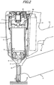
Fig. 1 is an explanatory section view of a basic structure of a gas combustion type striking machine according to a first exemplary embodiment. -
Fig. 2 is a partially sectional explanatory view of an operating state of the gas combustion type striking machine. -
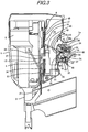
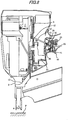
Fig. 3 is a partially longitudinal section view a mechanism and a neighboring portion of the mechanism of the first exemplary embodiment. -
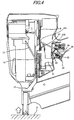
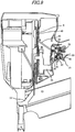
Fig. 4 is a partially longitudinal section view of a striking machine, showing a state thereof in which a contact member is pressed against a workpiece. -
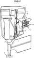
Fig. 5 is a partially longitudinal section view of the striking machine, showing a state in which a trigger is operated to start an operation of the striking machine. -
Fig. 6 is a partially longitudinal section view of the striking machine, showing a state in which the trigger is pulled at a full stroke. -
Fig. 7 is a partially longitudinal section view of the striking machine, showing a state in which the contact unit is pressed against the workpiece. -
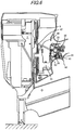
Fig. 8 is a partially longitudinal section view of the striking machine, showing a state in which the trigger is pulled to a position just before starting the operation of the striking machine to thereby hold a movable sleeve at its upper position. -
Fig. 9 is a partially longitudinal section view of the striking machine, showing a state in which the trigger is pulled first. -
Fig. 10 is a partially longitudinal section view of the striking machine, showing a state in which a contact member is next pressed against the workpiece. -
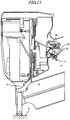
Fig. 11 is a partially longitudinal section view of the striking machine, showing a state in which the trigger is released. -
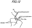
Fig. 12 is a partially longitudinal sectional explanatory view of the striking machine, showing a moving track of a safety lever and a contact area of the safety lever and a trigger switch lever. -
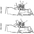
Figs. 13(A) and 13(B) are respectively explanatory view of operating modes of the safety lever respectively corresponding to the operation of the trigger. -
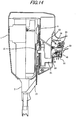
Fig. 14 is a longitudinal section view of main portions of a gas combustion type striking machine where a slide type trigger is adopted (according to a modification of the first exemplary embodiment). -
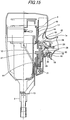
Fig. 15 is a partially longitudinal section view of a striking machine according to a second exemplary embodiment. -
Fig. 16 is a partially longitudinal section view of the striking machine shown inFig. 15 , showing a state in which the operation of the striking machine is started for nail driving. -
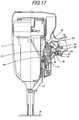
Fig. 17 is a partially longitudinal section view of the striking machine shown inFig. 15 , showing the state thereof in which the trigger is pulled first. - The description will be given hereinbelow on the basis of exemplary embodiments and a modification thereof with reference to the drawings. Further, the exemplary embodiments and the modification are not intended to limit the invention but to serve as examples thereof, and all features or combinations thereof described in the exemplary embodiments and the modification are not always essential to the invention.
-
Figs. 1 and2 are respectively section views of a basic structure of a gas combustion type striking machine of a first exemplary embodiment, in whichreference numeral 1 designates the body of the combustion type striking machine. In the interior portion of thebody 1, there is provided a striking mechanism and, downwardly of thebody 1, there is disposed anose portion 2 from which a nail can be driven. On the rear portion of the striking mechanism, there is mounted a gas can 9 filled with fuel gas which is produced by liquefying combustible gas. Also, to thebody 1, there are connected agrip 1a and amagazine 3, while themagazine 3 is structured such that it opens on thenose portion 2 and can supply a nail to thenose portion 2. - Referring to the structure of the striking mechanism, within a
cylinder 4 disposed within thebody 1, there is slidably provided apiston 5; and, within acombustion chamber 7 so closed formed as shown inFig. 2 by amovable sleeve 6 provided on the upper portion of the cylinder, combustible mixed gas is ignited and is combusted explosively, and thepiston 5 is driven by this high-pressure combustion gas to actuate adriver 8 integrally connected to thepiston 5, thereby striking a nail (not shown) existing within thenose portion 2.Reference numeral 10 designates a trigger which is used to start the operation of the striking machine. - Here, in a
cylinder head 11, there are provided aninjection nozzle 18 communicating with the gas can 9, an ignition plug (not shown) used to ignite and combust the mixed gas, and arotary fan 20 used to stir and mix combustible gas injected into thecombustion chamber 7 by theinjection nozzle 18 with the air existing within thecombustion chamber 7 to produce mixed gas having a given air/fuel rate. - The
combustion chamber 7 is defined by the upper end face of thepiston 5 and the ring-shapedmovable sleeve 6 interposed between thecylinder 4 and acylinder head 11 provided in the interior portion of the upper portion of thebody 1. When themovable sleeve 6, as shown inFig. 2 , is moved upwardly toward thecylinder head 11 for sealing, thecombustion chamber 7 is formed in a sealed or closed manner; whereas, when themovable sleeve 6 is moved downwardly as shown inFig. 1 , the upper portion of thecombustion chamber 7 can be opened to the air. - Next, the upward and downward movements of the
movable sleeve 6 are carried out in the following manner. That is, on the lower end of themovable sleeve 6, there is mounted aU-shaped chamber arm 12, while the lower end of thechamber arm 12 is so disposed as to be engageable with thereceiving portion 15 of the lower portion of aguide block 14 provided upwardly of a contact arm (contact member) 13. Thecontact arm 13 is constituted of multiple members connected together. And, thecontact arm 13 is structured such that it can slide freely in the upward and downward nail driving directions along thenose portion 2 and, when the lower end thereof is pressed against the workpiece, it can move relatively upwardly with respect to thenose portion 2. The upper portion of thecontact arm 13 is structured such that it can slide in the vertical direction along apartition wall 17 between thestorage portion 16 of a gas can (not shown) filled with fuel gas andcylinder 4. - Here, the
movable sleeve 6 is normally energized downwardly by a spring (not shown). Therefore, thecontact arm 13 is also so energized as to project from the lower end of thenose portion 2. - The above striking machine includes: a
slide arm 21 movable vertically according to the operation of thecontact arm 13; asafety lever 23 pivotally supported on ashaft 22 which is provided on the substantially central portion of the side wall of thetrigger 10 and can be engaged with theslide arm 21 through a torsion coil spring 36 (which will be discussed later); atrigger switch lever 25 provided on thebody 1, specifically, pivotally supported on ashaft 24 provided on the base portion of thegrip 1a so as to be engageable with thesafety lever 23; and, amicroswitch 26 which, when it is pressed by thetrigger switch lever 25, can ignite the above ignition plug. Thetrigger switch lever 25 is rotatable between an OFF position where the trigger switch lever does not engage with themicroswitch 26 and an ON position to engage with themicroswitch 26 so as to activate themicroswitch 26. - The
slide arm 21 is so disposed as to stride over the gas can stored within a gascan storage portion 16 and can be moved vertically along thepartition wall 17 between the gas canstorage portion 16 andcylinder 4. An engagingpiece 27 is provided on and projected from the front portion of theslide arm 21 and, specifically, the engagingpiece 27 penetrates through anopening 28 formed in thepartition wall 17 and projects toward thecylinder 4. Also, an engagingarm 30 is provided on and projected from the rear portion of theslide arm 21, while the leading end portion of theengaging arm 30 penetrates through anopening 31 formed in the rear wall of thebody 1 and projects outwardly therefrom. And, the engagingpiece 27 is disposed upwardly of theguide block 14 provided on the upper portion of thecontact arm 13 and, halfway in the upward movement of thecontact arm 13, the engagingpiece 27 can be engaged with theguide block 14. Also, the leading end portion of theengaging arm 30 projects toward thetrigger 10. - Next, one end of the
trigger 10 is pivotally supported on asupport shaft 32 interposed between thetrigger 10 andgrip 1a. - The
safety lever 23 includes alever portion 33, aspring receiving piece 34 and an engagingpiece 35 which are respectively extended radially from the central portion of thesafety lever 23. Thelever portion 33 is so disposed as to face upwardly, thespring receiving piece 34 extends substantially horizontally, and the engagingpiece 35 is so disposed as to face downwardly. And, on thespring receiving piece 34, there is mounted oneend 37 of thetorsion coil spring 36 mounted on theshaft 22, while the engagingpiece 35 can be engaged with a projectingportion 40 which projects upwardly from the lower wall of thetrigger 10. Theother end 38 of thetorsion coil spring 36 can be engaged with the upper end of theengaging arm 30 of theslide arm 21. Also, between thespring receiving piece 34 and the lower wall of thetrigger 10, there is interposed acoil spring 41. Therefore, thesafety lever 23 is so energized by thecoil spring 41 as to be rotatable counterclockwise in a direction toward a first position from a second position. The two ends 37 and 38 of thetorsion coil spring 36 are held at the same angle due to the elasticity thereof. Therefore, while thesafety lever 23 is held in the wait state, the engagingpiece 35 is energized by thecoil spring 41 and is thereby engaged with the projectingportion 40 of thetrigger 10. When theslide arm 21 moves upwardly, thesafety lever 23 is pushed up by the engagingarm 30 and is rotated to the right by thetorsion coil spring 36 against the spring force of thecoil spring 41, whereas, as shown inFig. 3 , when theslide arm 21 moves downwardly and theengaging arm 30 parts away from thetorsion coil spring 36, thesafety lever 23 is rotated to the left by the spring force of thecoil spring 41. - Upwardly of the
trigger 10, there is disposed themicroswitch 26 through thetrigger switch lever 25. - The leading end of the
trigger switch lever 25 is structured to be movable between two positions: specifically, one position at which, when thetrigger switch lever 25 rotates about theshaft 24, it can press against thecontact 26a of themicroswitch 26 to turn on themicroswitch 26; and, the other position at which it parts away from thecontact 26a. Also, thetrigger switch lever 25, in the wait state thereof, is held by acoil spring 39 in a substantially horizontal state in which it is separated from themicroswitch 26. This eliminates the possibility that thetrigger switch lever 25 can be swung due to inertia, which can be possibly generated when the striking machine is struck against a certain member, to thereby press against themicroswitch 26. - The
trigger switch lever 25, when thetrigger 10 is pulled and rotated upwardly, can be engaged with the leading end of thesafety lever 23 and, when thetrigger 10 is further pressed and rotated, can be pressed against themicroswitch 26. However, in the wait state, even when thetrigger switch lever 25 is rotated, thelever portion 33 passes the leadingend 42 of thetrigger switch lever 25, so that thetrigger switch lever 25 cannot press against themicroswitch 26. - Further, to the upper portion on the rotation center side of the
trigger 10, there is rotatably connected a metal-made lock-outbar 43 serving as a hold member. This lock-outbar 43 is also so disposed as not to interfere with the gas can 9, while the lock-outbar 43 penetrates through anopening 44 formed in thepartition wall 17 and projects toward thecylinder 4. And, the lock-outbar 43 is normally energized downwardly by atorsion coil spring 45 and is supported on a projectingshaft 46 which projects inwardly of the gas canstorage portion 16. The leading end of the lock-outbar 43, in its wait state, is held at a position corresponding to theside surface 49 of themovable sleeve 6. However, as will be described later, in the case that thetrigger 10 is rotated while themovable sleeve 6 stands in its wait state, theleading end 43L of the lock-outbar 43 is engaged with theside surface 49 of themovable sleeve 6; and, in the case that thetrigger 10 is rotated when themovable sleeve 6 moves upwardly, the leading end of the lock-outbar 43 is so moved as to be engageable with thelower surface 47 of themovable sleeve 6. - Here, since the
torsion coil spring 45 is engaged with the lock-outbar 43 andtrigger 10, thetrigger 10 is also normally energized such that it is moved to its lower wait position. - As described in the above, according to the first exemplary embodiment, the gas combustion type striking machine may include: the
body 1; thecylinder 4 arranged in thebody 1; thepiston 5 arranged slidably in the vertical direction in thecylinder 4; themovable sleeve 6 arranged in the upper portion of thecylinder 4; thecombustion chamber 7 which is opened and closed by moving themovable sleeve 6 in the vertical direction; thenose portion 2 arranged in the lower side of thebody 1 and from which the nail is driven out; thecontact member 13 projecting from thenose portion 2 to be slidable in the vertical direction and configured to upwardly move with respect to thebody 1 by being pressed against the workpiece so as to move themovable sleeve 6 in the closing direction to close thecombustion chamber 7; thetrigger 10; thesafety lever 23 attached to thetrigger 10 and arranged to be engageable with thecontact member 13; theswitch lever 25 arranged to be engageable with thesafety lever 23; theswitch 26 configured to be switched by being pressed by theswitch lever 25; and thehold member 43 rotatably connected to thetrigger 10 and arranged to be engageable with themovable sleeve 6. - The
safety lever 23 may be pivotally supported on theshaft 22 fixed on thetrigger 10 and rotatable between the first position and the second position with respect to thetrigger 10. Theswitch lever 25 may be pivotally supported on theshaft 24 fixed on thebody 1 and rotatable between the ON position where theswitch 26 is switched on and the OFF position where theswitch 26 is switched off. Theswitch 26 may be fixed on thebody 1. Thehold member 43 may have thebase end 43B pivotally supported on theshaft 100 fixed on thetrigger 10 and theleading end 43L which is engageable with themovable sleeve 6, and the intermediate portion of thehold member 43 between thebase end 43B and theleading end 43L is supported on the projectingshaft 46 fixed on thebody 1. Theshaft 100 supporting thebase end 43B may position between theshaft 24 supporting theswitch lever 25 and thecylinder 4 in the right-left direction which is perpendicular to the vertical direction. - The
leading end 43L of thehold member 43 may be arranged in the position to engage with thelower surface 47 of themovable sleeve 6 so as to hold thecombustion chamber 7 in the closed state, in the condition that themovable sleeve 6 is in the upper position to close the combustion chamber and that thetrigger 10 is pulled. - The combustion type striking machine may include the
slide arm 21 arranged to be slidable in the vertical direction with respect to thebody 1 and the engagingpiece 27 formed on the front side of theslide arm 21 and positioned in the upper side of theupper portion 14 of thecontact member 13. Thetorsion coil spring 36 may be attached to theshaft 22 on thetrigger 10 where thesafety lever 23 is supported, the oneend 37 of thetorsion coil spring 36 may be attached to thespring receiving piece 34 formed on thesafety lever 23, and theother end 38 of thetorsion coil spring 36 may be arranged to be engageable with the upper end of theengaging arm 30 formed on the rear portion of theslide arm 21. Thesafety lever 23 may be urged toward the first position by thespring 41. The engagingpiece 27 of theslide arm 21 may be arranged in the position to engage with theupper portion 14 of thecontact member 13 so as to upwardly move theslide arm 21, in the condition that thecontact member 13 is pressed against the workpiece and upwardly moves. Theother end 38 of thetorsion coil spring 36 may be arranged in the position to engage with the upper end of theengaging arm 30 so as to rotate thesafety lever 23 toward the second position, in the condition that theslide arm 21 upwardly moves. Thelever portion 33 formed on thesafety lever 23 may be arranged in the position to engage with theswitch lever 25 so as to rotate theswitch lever 25 from the OFF position to the ON position in the condition that thesafety lever 23 is in the second position and that thetrigger 10 is pulled, and not to engage with theswitch lever 25 in the condition that thesafety lever 23 is in the first position and that thetrigger 10 is pulled. - The engaging
arm 30 of theslide arm 21 may be arranged in the position to make theother end 38 of thetorsion coil spring 36 to downwardly move so as to rotate thesafety lever 23 toward the first position by thespring 41 without the engagement of thelever portion 33 of thesafety lever 23 with theswitch lever 23, in the condition that theleading end 43L of thehold member 43 engages with thelower surface 47 of themovable sleeve 6 to hold the closed state of thecombustion chamber 7 and that the pressing action of thecontact member 13 against the workpiece is released to make theslide arm 21 downwardly move with respect to thebody 1. - The
leading end 43L of thehold member 43 may be arranged in the position to engage with the side surface of themovable sleeve 6 in the condition that thecontact member 13 is in its bottom dead center and thetrigger 10 is pulled. - The
lever portion 33 of thesafety lever 23 may be arranged in the position to passes theswitch lever 25 to release the engagement between thelever portion 33 and theswitch lever 25, in the condition that theswitch lever 25 presses theswitch 26 to switch ON by the pulling operation of thetrigger 10 and that the trigger is further pulled thereafter. - The contact area "a" in which the
safety lever 23 andswitch lever 25 are in contact with each other as ranging from the switch-on state generated when thetrigger 10 is operated after thecontact member 13 is pressed against the workpiece P to thereby press thesafety lever 23 against theswitch lever 25 to the switch-off state generated when thesafety lever 23 passes theswitch lever 25 may be set to correspond to the length in which thesafety lever 23 andswitch lever 25 are in contact with each other while thecontact arm 13 is moving from its substantially middle position to its top dead center. - The
trigger 10 may be pivotally supported on theshaft 32 fixed on thebody 1. - The
lever portion 33 and thespring receiving piece 34 may be respectively formed to radially extend on thesafety lever 23. - Next, description will be given below of the operation of the striking machine.
- When driving a nail, firstly, as shown in
Fig. 4 , the lower end of thecontact arm 13 is pressed against a workpiece P. Thus, since thechamber arm 12, together with thecontact arm 13, is also moved relatively upwardly with respect to thenose portion 2, themovable sleeve 6 is pushed up, thereby forming aclosed combustion chamber 7. When thecombustion chamber 7 is closed, as described above, combustible gas is injected from the injection nozzle into thecombustion chamber 7 and a motor is driven to rotate therotary fan 20, thereby stirring and mixing together the combustible gas and the air. - Here, halfway in the upward movement of the
contact arm 13, theguide block 14 of the upper portion of thecontact arm 13 is engaged with the engagingpiece 27 of theslide arm 21, whereby theslide arm 21 is moved upwardly. Thus, the engagingarm 30 of theslide arm 21 is engaged with and is pushed up theend portion 38 of thetorsion coil spring 36, whereby thesafety lever 23 is rotated to the right. - In this state, when, as shown in
Fig. 5 , thetrigger 10 is pulled up and rotated, just before the rotating end thereof, the leading end of thelever portion 33 of thesafety lever 23 is engaged with the lower surface of theleading end 42 of thetrigger switch lever 25 to push it up, whereby thetrigger switch lever 25 is rotated upwardly and is pressed against themicroswitch 26. As a result of this, since a switch included in a circuit connected to the ignition plug is turned on, mixed gas within thecombustion chamber 7 is ignited, combusted and expanded explosively. The pressure of this combustion gas, as described above, is applied to the upper surface of thepiston 5 to impactively drive thepiston 5 downwardly, whereby thepiston 5 strikes the leading one of nails within themagazine 3 respectively supplied into thenose portion 2 to thereby drive it into the workpiece P. - Here, when the
trigger 10 is pulled up by full stroke, as shown inFig. 6 , thesafety lever 23 is moved further upwardly and thus theslide arm 21 is moved relatively downwardly, whereby the end portion of thetorsion coil spring 36 is separated from the engagingarm 30 of theslide arm 21. Due to this, thesafety lever 23 is rotated to the left by the spring force of thecoil spring 41 and thus it passes the leading end of thetrigger switch lever 25. Also, due to the rotation of thetrigger 10, the lock-outbar 43 is moved downwardly of thelower surface 47 of themovable sleeve 6 which has moved upwardly. And, in the case that the whole of the driving machine is lifted up due to the reaction that is generated when driving the nail, themovable sleeve 6 is relatively lowered from the top dead center thereof. However, when thetrigger 10 is rotated, the end portion of the lock-outbar 43 sticks out downwardly of thelower surface 47 of themovable sleeve 6, whereby thelower surface 47 of themovable sleeve 6 having moved downwardly is engaged with the sticking-out end portion of the lock-outbar 43, thereby preventing themovable sleeve 6 from lowering any further. Therefore, thecombustion chamber 7 can be held in a closed state. - When the nailing operation is completed, since the temperature within the
combustion chamber 7 lowers suddenly, a space existing upwardly of thepiston 5 and enlarged up to thecylinder 4 inFig. 2 becomes negative in pressure. Thus, thepiston 5 is caused to return to the top dead center due to a difference between the pressure of the space and the pressure of the atmospheric pressure coming from below. And, the striking machine is pulled up to separate thenose portion 2 from the workpiece, and thetrigger 10 is released and is rotated downwardly, whereby the lock-outbar 43 is moved apart from themovable sleeve 6. Thus, due to the energizing force of the spring, themovable sleeve 6 andcontact arm 13 are moved downwardly to thereby open thecombustion chamber 7, the combustion gas is discharged and fresh air is taken in, whereby the striking machine is returned to the wait state shown inFig. 1 and thus a next nailing operation is prepared. - Here, in the above structure, firstly, as shown in
Fig. 7 , while thecontact arm 13 is pressed against the workpiece P, themovable sleeve 6 is moved upwardly to turn thecombustion chamber 7 into a closed state. After then, in order to maintain this state, as shown inFig. 8 , thetrigger 10 is pulled just before it is pressed against themicroswitch 26, the lock-outbar 43 is moved downwardly of thelower surface 47 of themovable sleeve 6 and further thenose portion 2 is detached from the workpiece P. As a result of this, as described above, themovable sleeve 6 is lowered from the top dead center and the end portion of the lock-outbar 43 is engaged with thelower surface 47, thereby being able to maintain the closed state of thecombustion chamber 7. However, thecontact arm 13 is also moved downwardly together with themovable sleeve 6 and, at the same time, theslide arm 21 is also moved downwardly, whereby the engagingarm 30 is lowered. Due to this, thesafety lever 23 loses the support of thetorsion coil spring 36 and, without being pressed sufficiently against thetrigger switch lever 25 by the spring force of thecoil spring 41, thelever portion 33 is rotated to the left while passing the leadingend 42 thereof. Therefore, even when thetrigger 10 is pulled by full stroke after then, since thesafety lever 23 cannot press against thetrigger switch lever 25 any longer, the striking machine cannot be started. Thus, the striking machine is not able to strike a nail in the air to discharge it. - When the
trigger 10 is released, thesafety lever 23 returns while rotating to the right, while themovable sleeve 6 andcontact arm 13 respectively lose their support and are thereby moved to their lower wait positions. At the same time, theslide arm 21 also returns to its wait position. Therefore, when the trigger 19 is pulled while thecontact arm 13 is being pressed against the workpiece, a nail can be driven actually. - Next, in the above structure, also when the
contact arm 13 is pressed against the workpiece after thetrigger 10 is pulled first, the striking machine is prevented from starting. That is, as shown inFig. 9 , when thetrigger 10 is pulled in a state where thecontact arm 13 stands at the lower wait position, since theslide arm 21 also stays at the lower wait position, thetorsion coil spring 36 does not act on thesafety lever 23 but thesafety lever 23 is energized to the left by thecoil spring 41, while thelever portion 33 passes the leading end of thetrigger switch lever 25. The engagingpiece 35 is engaged with the projecting portion of thetrigger 10. Also, when thetrigger 10 is rotated while themovable sleeve 6 stays in the wait state in this manner, the end portion of the lock-outbar 43 is contacted with theside surface 49 of themovable sleeve 6 and is further allowed to slide up along theside surface 49. After then, as shown inFig. 10 , even when thecontact arm 13 is pressed against the workpiece P, since, as described above, thesafety lever 23 has passed the position for operating thetrigger switch lever 25, the striking machine is prevented from starting even when theslide arm 21 is moved upwardly. In this state, since the lock-outbar 43 remains engaged with theside surface 49 of themovable sleeve 6, themovable sleeve 6 cannot be held at the upper position. That is, when thetrigger 10 is operated first in this manner, the striking machine cannot be actuated. - In the above structure, as shown in
Fig. 11 , when thetrigger 10 is returned to the wait state and thesafety lever 23 is rotated to the right and is thereby returned to the wait position, firstly, thecontact arm 13 is pressed against the workpiece P. Therefore, when thetrigger 10 is operated again, thesafety lever 23 rotates thetrigger switch lever 25 to turn on themicroswitch 26, whereby the striking machine can be started. - Here, as shown in
Fig. 12 , the leading end of thecontact arm 13 is pressed against the workpiece and then, by operating thetrigger 10, the leading end edge of thelever portion 33 of thesafety lever 23 is engaged with thelower surface 25a of thetrigger switch lever 25. After then, when thesafety lever 23 is moved upwardly, it is pressed against themicroswitch 26 to turn it on. When the leading end edge of thelever portion 33 moves from a contact point, at which themicroswitch 26 is turned on, and passes thelower surface 25a of thetrigger switch lever 25, themicroswitch 26 is turned off. A contact area a, in which the leading end edge of thelever portion 33 is moving while the leading end edge of thelever portion 33 and thelower surface 25a of thetrigger switch lever 25 are in contact with each other, is defined as an area in which thelever portion 33 of thesafety lever 23 can be contacted with thetrigger switch lever 25 while, when thecontact arm 13 is moved from the bottom dead center, it is moving from a substantially middle point to the top dead center. Therefore, in the case that, in a state where thecontact arm 13 has moved to or higher than the substantially middle point, thetrigger 10 is pulled to thereby start the operation of the striking machine, even when the timing of the machine starting operations (the time at which thetrigger switch lever 25 is pulled) differ between operators, within the contact area a where the leading end edge of thelever portion 33 is moving while it is in contact with thelower surface 25a of thetrigger switch lever 25, by pressing themicroswitch 26, the driving machine can be started. Therefore, in the case that, in order to drive a nail quickly, thetrigger 10 is pulled while the driving machine is pressed against the workpiece, the timing of the machine starting operation differs between the operators but, because the timing difference can be absorbed, the driving machine can be started positively. - Also, according to the above driving machine structure, since there is not used a cam which is necessary in a conventional driving machine, there is eliminated the need to pay attention to the influence of heat which is generated due to combustion of gas. Due to this, the space for storing the cam can be used effectively or such space can be saved to thereby reduce the whole height of the driving machine. And, the cost of the driving machine can also be reduced.
- Also, since the lock-out
bar 43 is rotatably disposed on the rotation center side of thetrigger 10, there can be secured a large space in the upper portion of the trigger (a portion between thebody 1 andgrip 1a). In such space, there can be disposed a switch mechanism such as a safety lever, a switch lever, a switch and the like. This makes it possible to use the space of the upper portion of the trigger effectively and also can save a space where the conventional switch mechanism is provided. Therefore, the whole of the driving machine can be made compact. - Further, since the
trigger 10 is structured such that it can move themovable sleeve 6 through the lock-outbar 43 to turn thecombustion chamber 7 into a closed state, the structure of the striking machine can be simplified, the number of parts thereof can be reduced and the whole height thereof can be reduced, whereby the whole of the striking machine can be made compact. Here, when moving themovable sleeve 6 downwardly in order to open thecombustion chamber 7, the lock-outbar 43 is pushed back by themovable sleeve 6 and is thereby separated from the lower surface of themovable sleeve 6. However, when the lock-outbar 43 is pushed back, thetrigger 10 is also pushed back, thereby being able to reduce a spring load necessary to pull back thetrigger 10 to the wait position. Therefore, the operation efficiency of thetrigger 10 can also be enhanced. - Also, in the case that the
trigger 10 is pulled first in order to carry out a so called contact nailing operation in which a nail is driven simply by applying the striking machine to the workpiece while thetrigger 10 remains pulled, when thetrigger 10 is rotated, thesafety lever 23 passes thetrigger switch lever 25 with no contact with it. Therefore, after then, even when thecontact arm 13 is pressed against the workpiece, the striking machine is prevented against operation. Also, when thetrigger 10 is rotated, the end portion of the lock-outbar 43 simply slides up along the side surface of the movable sleeve 6 (seeFig. 10 ). Therefore, even when an operator operates thetrigger 10 while gripping it strongly, or even when the operator strikes in error the leading end of the striking machine against the workpiece strongly, no load is applied to the lock-outbar 43 ortrigger 10, thereby being able to prevent them against deformation or damage. This makes it possible to protect the parts of the striking machine properly. - Also, although shown in
Fig. 6 as well, as shown inFig. 13(A) , halfway in the rotation movement of thetrigger 10 when carrying out the nailing operation, thesafety lever 23 is engaged with thetrigger switch lever 25 to allow it to press against themicroswitch 26. After then, as shown inFig. 13(B) , when thetrigger 10 is rotated at full stroke up to the rotation end thereof, thelever portion 33 of thesafety lever 23 passes thetrigger switch lever 25 to thereby remove its engagement with thetrigger switch lever 25. Due to this structure, it is possible to positively prevent the damage and thus breakdown of themicroswitch 26 which is caused due to the over-depressing of themicroswitch 26. Here, when thetrigger 10 is returned, thesafety lever 23 lowers while rotating and, halfway in the lowering movement, thesafety lever 23 is engaged with the leading end of thetrigger switch lever 25. However, since thesafety lever 23 does not act on thetrigger switch lever 25 in such a manner that it moves thetrigger switch lever 25 upwardly, thetrigger 10 can be returned to the wait state. Thus, since themicroswitch 26 is pressed only when thetrigger 10 is pulled first, thetrigger 10 is effective also when it is used as a safety device. - Here, since the above-mentioned
trigger 10 is rotatably supported on theshaft 32 on thebody 1 side, there is no possibility that the sliding surface of the trigger 19 can be damaged by dust or sand generated in a working site to slow the movement of thetrigger 10 and also that the parts of thetrigger 10 can be worn. Therefore, the performance of thetrigger 10 is hard to deteriorate and there is no need to add a wear-preventive part. However, since thetrigger 10 fulfills the above-mentioned functions through its vertical movement between theslide arm 21 and triggerswitch lever 25, thetrigger 10 is not limited to the type that, as in the first exemplary embodiment, the trigger can be moved vertically due to the rotational movement thereof. For example, like atrigger 10 as shown inFig. 14 , according to a modification, there may also be employed a structure of a slide type that thetrigger 10 can be slid vertically. In this case as well, the slide-type trigger 10 operates substantially similarly to the first exemplary embodiment and thus the description thereof is omitted here. -
Fig. 15 shows a second exemplary embodiment in which a switch mechanism is disposed near a cylinder. This embodiment is substantially the same in the basic structure as the first exemplary embodiment and thus parts used in common are given the same designations. - In the present embodiment as well, when driving a nail, firstly, as shown in
Fig. 16 , the lower end of thecontact arm 13 is pressed against the workpiece P. Since thechamber arm 12 is also moved together with thecontact arm 13 relatively to thenose portion 2, themovable sleeve 6 is pushed up, theclosed combustion chamber 7 is formed, and combustible gas injected into thecombustion chamber 7 is stirred and mixed with the air normally existing within thecombustion chamber 7. At the same time, theguide block 14 is engaged with theslide arm 21 to thereby move it upwardly, and theengaging arm 30 pushes up one end of thetorsion coil spring 36, thereby causing thesafety lever 23 to rotate. In this state, when thetrigger 10 is pulled up, just before the rotation end of the trigger, the leading end of thelever portion 33 of thesafety lever 23 pushes up thetrigger switch lever 25 to thereby turn on themicroswitch 26. As a result of this, the nail is struck out. - When the nail driving operation is completed, the temperature within the
combustion chamber 7 lowers suddenly, whereby thepiston 5 is returned to the top dead center due to a difference in pressure between a space existing upwardly of thepiston 5 and the air existing downwardly of thepiston 5. And, the striking machine is pulled up to separate thenose portion 2 from the workpiece, and thetrigger 10 is released and rotated downwardly, whereby the striking machine returns to the wait state and a next nailing operation is prepared. - Next, in the above structure, as shown in
Fig. 17 , after thetrigger 10 is pulled first, even when thecontact arm 13 is pressed against the workpiece, the striking machine is prevented against operation. That is, when thetrigger 10 is pulled with thecontact arm 13 standing at the lower wait position, since theslide arm 21 also stands at the lower position, thetorsion coil spring 36 is prevented from acting on thesafety lever 23, but thesafety lever 23 is energized to the left by thecoil spring 41, whereby thelever portion 33 passes the leading end of thetrigger switch lever 25. Therefore, after then, even when theslide arm 21 is moved upwardly by pressing thecontact arm 13 against the workpiece P, the striking machine is prevented against actuation. In this manner, when thetrigger 10 is operated first, the striking machine cannot be started. Therefore, a so called contact nailing operation can also be prevented. - According to the above structure, since the lock-out
bar 43 is rotatably disposed on the upper portion of the rotation center side of thetrigger 10, similarly to the embodiment shown inFig. 1 , in the upper portion of the trigger 10 (between thebody 1 andgrip 1a), there is secured a large space and, in this large space, there can be disposed a switch mechanism such as a safety lever, a switch lever, a switch and the like. Thanks to this, the upper portion space of thetrigger 10 can be used effectively and also a space where a conventional switch mechanism has existed can be omitted, whereby the whole of the striking machine can be made compact. - Further, since the gas can 9 is not interposed between the
body 1 andgrip 1a as shown inFig. 1 , the switch mechanism can be disposed near the cylinder. This can reduce the distance from the body and grip to the trigger, and thus the position of center of gravity of the striking machine can be got nearer the body, which can improve the weight balance of the striking machine and thus the stability and operation efficiency thereof in its nail driving operation. - Also, the trigger may have a slide type structure instead of a rotation type structure.
- According to the structure of the exemplary embodiments, when driving a nail, by pressing the lower end of the contact member against the workpiece, the movable sleeve is pushed up together with the contact member, whereby there is formed a closed combustion chamber. During the upward movement of the contact member, when the trigger is operated after the safety lever is operated, the safety lever is engaged with the switch lever and presses against it, whereby the switch lever pushes the switch into operation. As a result of this, since the switch of a circuit connected to an ignition plug is turned on, the mixed gas within the combustion chamber is ignited, combusted and expanded explosively. This high-pressure combustion gas is applied to the piston to drive it impactively and, using a driver connected to the lower surface side of the piston, a nail is driven out from the nose portion into the workpiece.
- Also, since the hold member is rotatably disposed on the rotation center side of the trigger, there can be secured a large space in the upper portion of the trigger and, in this space, there can be provided a switch mechanism such as a safety lever, a switch lever, a switch and the like. This makes it possible to make effective use of the space of the trigger upper portion and also to save a space where a conventional switch mechanism has been provided. Therefore, the whole of the striking machine can be made compact.
- Further, since the distance between the body and trigger can be reduced and thus the position of center of gravity of the striking machine can be set nearer the body, the weight balance of the striking machine as a machine can be enhanced. This allows a user to operate the striking machine easily and also can make it harder for the user to be tired.
- To the trigger, there is connected a hold member extending toward the movable sleeve; and, the leading end of the hold member, when the movable sleeve moves upward, in linking with the operation of the trigger, is engaged with the lower surface of the movable sleeve to thereby hold the combustion chamber in a closed state. According to this structure, there can be formed a combustion chamber which is closed by the trigger and hold member, the structure of the striking machine can be simplified, the number of parts thereof can be reduced, and the whole height thereof can be reduced, whereby the whole of the striking machine can be made compact. Further, when moving the movable sleeve downwardly in order to open the combustion chamber, the hold member is pushed back by the movable sleeve and is separated from the lower surface of the movable sleeve; and, specifically, since, when the hold member is pushed back, the trigger is also returned, there can be reduced a spring load for returning the trigger.
- In a state where the trigger is rotated halfway and the end portion of the hold member is engaged with the lower surface of the movable sleeve having lowered down to a position slightly downwardly of the top dead center to thereby hold the combustion chamber in a closed state, the slide arm movable with the lowering movement of the movable sleeve rotates the safety lever in such a manner that the leading end of the safety lever is allowed to pass the leading end of the switch lever. Therefore, after then, even when the trigger is pulled, the safety lever cannot press against the switch lever any longer, whereby the operation of the striking machine cannot be started. Thus, it is not possible to strike a nail in the air and discharge it.
- When the trigger is operated while the slide arm stands at its lower position, the slide arm rotates the safety lever in such a manner that the leading end of the safety lever is allowed to pass the leading end of the switch lever. Therefore, even when the switch lever is rotated, the lever portion of the safety lever is allowed to pass the leading end of the switch lever. Thus, after then, even when the contact member is pressed against the workpiece, the striking machine will not be started. Therefore, in the case that the trigger is operated first, the operation of the striking machine cannot be started.
- When the trigger is operated while the contact member stands at its top dead center, the leading end of the hold member is engaged with the side surface of the movable sleeve. Thanks to this, since, when the trigger is rotated, the end portion of the hold member simply slides up along the side surface of the movable sleeve, the end portion of the hold member does not interfere with the operation of the trigger. Therefore, even when the leading end of the striking machine is strongly struck against the workpiece in error, any load can be applied neither to the hold member nor to the trigger, which eliminates a fear that they can be deformed or damaged. Accordingly, the parts of the striking machine can be protected properly.
- When the trigger is operated after the contact member is pressed against the workpiece, halfway in the operation of the trigger, the safety lever is engaged with the switch lever; and, after the switch lever is pressed against the switch, at the rotation end of the trigger, the safety lever passes the switch lever and parts away from it. Thanks to this structure, the damage and thus failure of the switch due to the over-pressing thereof can be positively prevented.
- Such contact area of the contact portions of the safety lever and switch lever as ranging from a switch-on state generated when the trigger is operated after the contact member is pressed against the workpiece to thereby press the safety lever against the switch lever to a switch-off state generated when the safety lever passes the switch lever is set to correspond to the time during which the two levers are in contact with each other while the contact arm is moving from substantially the middle position to the top dead center. Thanks to this, when the trigger is pulled for actuation of the striking machine in a state where the contact arm has moved upward to or higher than substantially at the middle position, even if the timing for actuation of the machine varies according to operators, during the contact area where the safety lever and switch lever are moving in contact, by pressing the microswitch, the striking machine can be actuated positively.
- The trigger is rotatably supported on a shaft on the body side. Due to this, when compared with a slide type structure, there is no possibility that the sliding surface of the trigger can be damaged by dust or sand generated in a working site to thereby slow the movement of the
trigger 10, and also that the parts of the trigger can be worn. Therefore, the performance of the trigger is hard to deteriorate and there is no need to add a wear-preventive part. -
- 1:
- Body
- 2:
- Nose portion
- 4:
- Cylinder
- 5:
- Piston
- 6:
- Movable sleeve
- 10:
- Trigger
- 13:
- Contact member
- 21:
- Slide arm
- 23:
- Safety lever
- 25:
- Trigger switch lever
- 26:
- Microswitch
- 43:
- Lock-out bar
Claims (10)
- A gas combustion type striking machine comprising:a body (1);a cylinder (4) arranged in the body (1);a piston (5) arranged slidably in a vertical direction in the cylinder (4);a movable sleeve (6) arranged in an upper portion of the cylinder (4);a combustion chamber (7) which is opened and closed by moving the movable sleeve (6) in the vertical direction;a nose portion (2) arranged in a lower side of the body (1) and from which a nail is driven out;a contact member (13) projecting from the nose portion (2) to be slidable in the vertical direction and configured to upwardly move with respect to the body (1) by being pressed against a workpiece so as to move the movable sleeve (6) in a closing direction to close the combustion chamber (7);a trigger (10);a safety lever (23) pivotally supported on a shaft (22) fixed on the trigger (10) and rotatable between a first position and a second position with respect to the trigger (10) and arranged to be moveably linked to the movement of the contact member (13), wherein a torsion coil spring (36) is supported on the shaft (22) fixed on the trigger (10), wherein the safety lever (23) is configured to be engaged with the trigger (10) directly,a switch lever (25) arranged to be engageable with the safety lever (23);a switch (26) disposed upwardly of the trigger (10) configured to be switched by being pressed by the switch lever (25); anda hold member (43) rotatably connected to the trigger (10) and arranged to be engageable with the movable sleeve (6).
- The gas combustion type striking machine according to claim 1,
wherein the switch lever (25) is pivotally supported on a shaft (24) fixed on the body (1) and rotatable between an ON position where the switch (26) is switched on and an OFF position where the switch (26) is switched off, and
wherein the switch (26) is fixed on the body (1),
wherein the hold member (43) has a base end (43B) pivotally supported on a shaft (100) fixed on the trigger (10) and a leading end (43L) which is engageable with the movable sleeve (6), and an intermediate portion of the hold member (43) between the base end (43B) and the leading end (43L) is supported on a projecting shaft (46) fixed on the body (1), and
wherein the shaft (100) supporting the base end (43B) positions between the shaft (24) supporting the switch lever (25) and the cylinder (4) in a right-left direction which is perpendicular to the vertical direction. - The gas combustion type striking machine according to claim 2, wherein the leading end (43L) of the hold member (43) is arranged in a position to engage with a lower surface (47) of the movable sleeve (6) so as to hold the combustion chamber (7) in a closed state, in a condition that the movable sleeve (6) is in an upper position to close the combustion chamber and that the trigger (10) is pulled.
- The gas combustion type striking machine according to claim 2 or 3, further comprising:a slide arm (21) arranged to be slidable in the vertical direction with respect to the body (1),wherein an engaging piece (27) is formed on a front side of the slide arm (21) and positioned in an upper side of an upper portion (14) of the contact member (13),wherein an one end (37) of the torsion coil spring (36) is attached to a spring receiving piece (34) formed on the safety lever (23), and the other end (38) of the torsion coil spring (36) is arranged to be engageable with an upper end of an engaging arm (30) formed on a rear portion of the slide arm (21),wherein the safety lever (23) is urged toward the first position by a spring (41),wherein the engaging piece (27) of the slide arm (21) is arranged in a position to engage with the upper portion (14) of the contact member (13) so as to upwardly move the slide arm (21), in a condition that the contact member (13) is pressed against the workpiece and upwardly moves,wherein the other end (38) of the torsion coil spring (36) is arranged in a position to engage with the upper end of the engaging arm (30) so as to rotate the safety lever (23) toward the second position, in a condition that the slide arm (21) upwardly moves, andwherein a lever portion (33) formed on the safety lever (23) is arranged in a position to engage with the switch lever (25) so as to rotate the switch lever (25) from the OFF position to the ON position in a condition that the safety lever (23) is in the second position and that the trigger (10) is pulled, and not to engage with the switch lever (25) in a condition that the safety lever (23) is in a first position and that the trigger (10) is pulled.
- The gas combustion type striking machine according to claim 4, wherein the engaging arm (30) of the slide arm (21) is arranged in a position to make the other end (38) of the torsion coil spring (36) to downwardly move so as to rotate the safety lever (23) toward the first position by the spring (41) without an engagement of the lever portion (33) of the safety lever (23) with the switch lever (23), in a condition that the leading end (43L) of the hold member (43) engages with the lower surface (47) of the movable sleeve (6) to hold the closed state of the combustion chamber (7) and that a pressing action of the contact member (13) against the workpiece is released to make the slide arm (21) downwardly move with respect to the body (1).
- The gas combustion type striking machine according to any one of claims 3 to 5, wherein the leading end (43L) of the hold member (43) is arranged in a position to engage with a side surface of the movable sleeve (6) in a condition that the contact member (13) is in its bottom dead center and the trigger (10) is pulled.
- The gas combustion type striking machine according to any one of claims 4 to 6, wherein the lever portion (33) of the safety lever (23) is arranged in a position to passes the switch lever (25) to release an engagement between the lever portion (33) and the switch lever (25), in a condition that the switch lever (25) presses the switch (26) to switch ON by an pulling operation of the trigger (10) and that the trigger is further pulled thereafter.
- The gas combustion type striking machine according to claim 7, wherein a contact area (a) in which the safety lever (23) and switch lever (25) are in contact with each other as ranging from a switch-on state generated when the trigger (10) is operated after the contact member (13) is pressed against the workpiece (P) to thereby press the safety lever (23) against the switch lever (25) to a switch-off state generated when the safety lever (23) passes the switch lever (25) is set to correspond to a length in which the safety lever (23) and switch lever (25) are in contact with each other while the contact arm (13) is moving from its substantially middle position to its top dead center.
- The gas combustion type striking machine according to any one of claims 1 to 8, wherein the trigger (10) is pivotally supported on a shaft (32) fixed on the body (1).
- The gas combustion type striking machine according to any one of claims 1 to 9, wherein a lever portion (33) and a spring receiving piece (34) are respectively formed to radially extend on the safety lever (23).
Priority Applications (1)
| Application Number | Priority Date | Filing Date | Title |
|---|---|---|---|
| PL11006224T PL2428320T3 (en) | 2010-08-12 | 2011-07-28 | Gas combustion type striking machine |
Applications Claiming Priority (1)
| Application Number | Priority Date | Filing Date | Title |
|---|---|---|---|
| JP2010181011A JP5447285B2 (en) | 2010-08-12 | 2010-08-12 | Gas fired driving tool |
Publications (3)
| Publication Number | Publication Date |
|---|---|
| EP2428320A2 EP2428320A2 (en) | 2012-03-14 |
| EP2428320A3 EP2428320A3 (en) | 2018-02-21 |
| EP2428320B1 true EP2428320B1 (en) | 2019-11-13 |
Family
ID=45044826
Family Applications (1)
| Application Number | Title | Priority Date | Filing Date |
|---|---|---|---|
| EP11006224.7A Active EP2428320B1 (en) | 2010-08-12 | 2011-07-28 | Gas combustion type striking machine |
Country Status (8)
| Country | Link |
|---|---|
| US (1) | US8915415B2 (en) |
| EP (1) | EP2428320B1 (en) |
| JP (1) | JP5447285B2 (en) |
| CN (1) | CN102398250B (en) |
| ES (1) | ES2756626T3 (en) |
| HU (1) | HUE048354T2 (en) |
| PL (1) | PL2428320T3 (en) |
| TW (1) | TWI572459B (en) |
Families Citing this family (6)
| Publication number | Priority date | Publication date | Assignee | Title |
|---|---|---|---|---|
| EP3181295A1 (en) * | 2015-12-18 | 2017-06-21 | HILTI Aktiengesellschaft | Internal combustion operated driving tool |
| EP3184250A1 (en) * | 2015-12-22 | 2017-06-28 | HILTI Aktiengesellschaft | Internal combustion gas operated driving tool |
| FR3046741B1 (en) | 2016-01-20 | 2018-01-05 | Illinois Tool Works Inc | GAS FASTENING TOOL |
| TWI600510B (en) * | 2016-08-22 | 2017-10-01 | Trigger mechanism to switch firing mode pneumatic tools | |
| US11141845B2 (en) * | 2017-02-02 | 2021-10-12 | Illinois Tool Works Inc. | Combustion-powered tool with sleeve-retaining lockout device |
| WO2020184218A1 (en) * | 2019-03-14 | 2020-09-17 | 工機ホールディングス株式会社 | Driving machine |
Family Cites Families (17)
| Publication number | Priority date | Publication date | Assignee | Title |
|---|---|---|---|---|
| US4629106A (en) * | 1985-05-29 | 1986-12-16 | Signode Corporation | Actuating means for fastener driving tool |
| JPH0647665Y2 (en) * | 1990-03-29 | 1994-12-07 | マックス株式会社 | Nailer safety device |
| US5083694A (en) * | 1991-06-11 | 1992-01-28 | Stanley-Bostitch, Inc. | Fastener driving device with sequential actuation trigger assembly |
| JPH0753907Y2 (en) * | 1991-12-27 | 1995-12-13 | マックス株式会社 | Nailer safety device |
| US5193730A (en) * | 1991-06-14 | 1993-03-16 | Max Co., Ltd. | Pneumatic nailing machine |
| US5680980A (en) * | 1995-11-27 | 1997-10-28 | Illinois Tool Works Inc. | Fuel injection system for combustion-powered tool |
| US5862969A (en) * | 1997-09-17 | 1999-01-26 | De Poan Pneumatic Corporation | Safety trigger for nailer |
| US6145724A (en) | 1997-10-31 | 2000-11-14 | Illinois Tool Works, Inc. | Combustion powered tool with combustion chamber delay |
| US5909836A (en) | 1997-10-31 | 1999-06-08 | Illinois Tool Works Inc. | Combustion powered tool with combustion chamber lockout |
| TW520691U (en) * | 2001-12-31 | 2003-02-11 | Panrex Ind Co Ltd | Percussion apparatus for nailing gun |
| US6659324B1 (en) * | 2003-05-20 | 2003-12-09 | Liu Chung-Ho | Single-firing trigger mechanism for a nailing machine |
| JP4102998B2 (en) * | 2003-09-10 | 2008-06-18 | マックス株式会社 | Nailer starter |
| JP4063233B2 (en) | 2004-03-12 | 2008-03-19 | マックス株式会社 | Combustion gas nailer |
| JP4353092B2 (en) | 2004-12-20 | 2009-10-28 | 日立工機株式会社 | Combustion nailer |
| US7931181B2 (en) * | 2005-02-18 | 2011-04-26 | Hitachi Koki Co., Ltd. | Combustion-type power tool with trigger control arrangements |
| JP4935978B2 (en) * | 2006-08-09 | 2012-05-23 | マックス株式会社 | Valve device for combustion chamber in gas-fired driving tool |
| JP5003259B2 (en) * | 2007-04-12 | 2012-08-15 | マックス株式会社 | Gas internal combustion nailer |
-
2010
- 2010-08-12 JP JP2010181011A patent/JP5447285B2/en active Active
-
2011
- 2011-07-15 TW TW100125085A patent/TWI572459B/en active
- 2011-07-26 US US13/190,569 patent/US8915415B2/en active Active
- 2011-07-28 HU HUE11006224A patent/HUE048354T2/en unknown
- 2011-07-28 PL PL11006224T patent/PL2428320T3/en unknown
- 2011-07-28 ES ES11006224T patent/ES2756626T3/en active Active
- 2011-07-28 EP EP11006224.7A patent/EP2428320B1/en active Active
- 2011-08-12 CN CN201110236667.8A patent/CN102398250B/en active Active
Non-Patent Citations (1)
| Title |
|---|
| None * |
Also Published As
| Publication number | Publication date |
|---|---|
| JP2012040616A (en) | 2012-03-01 |
| TWI572459B (en) | 2017-03-01 |
| US20120037681A1 (en) | 2012-02-16 |
| EP2428320A2 (en) | 2012-03-14 |
| US8915415B2 (en) | 2014-12-23 |
| JP5447285B2 (en) | 2014-03-19 |
| TW201206652A (en) | 2012-02-16 |
| EP2428320A3 (en) | 2018-02-21 |
| CN102398250A (en) | 2012-04-04 |
| HUE048354T2 (en) | 2020-07-28 |
| PL2428320T3 (en) | 2020-05-18 |
| CN102398250B (en) | 2015-11-25 |
| ES2756626T3 (en) | 2020-04-27 |
Similar Documents
| Publication | Publication Date | Title |
|---|---|---|
| EP2428320B1 (en) | Gas combustion type striking machine | |
| JP4877457B2 (en) | Nail feed delay mechanism for gas fired driving tools | |
| CN1929957B (en) | Combustion gas nailing machine | |
| KR100768607B1 (en) | Powered nailing machine | |
| JP4935978B2 (en) | Valve device for combustion chamber in gas-fired driving tool | |
| CN101511547B (en) | Gas combustion-type driving tool | |
| JP4780282B2 (en) | Fastener feed delay mechanism for gas fired driving tools | |
| JP5003259B2 (en) | Gas internal combustion nailer | |
| JP2009178819A (en) | Driving machine | |
| TWI421155B (en) | Into the tool | |
| JP4877470B2 (en) | Contact strike prevention mechanism of gas combustion type driving tool | |
| JP2007075957A (en) | Single driving holding mechanism of nailing machine | |
| JP5277728B2 (en) | Driving machine | |
| JP2011156607A (en) | Combustion type nailing machine |
Legal Events
| Date | Code | Title | Description |
|---|---|---|---|
| AK | Designated contracting states |
Kind code of ref document: A2 Designated state(s): AL AT BE BG CH CY CZ DE DK EE ES FI FR GB GR HR HU IE IS IT LI LT LU LV MC MK MT NL NO PL PT RO RS SE SI SK SM TR |
|
| AX | Request for extension of the european patent |
Extension state: BA ME |
|
| PUAI | Public reference made under article 153(3) epc to a published international application that has entered the european phase |
Free format text: ORIGINAL CODE: 0009012 |
|
| RIN1 | Information on inventor provided before grant (corrected) |
Inventor name: YOKOCHI, YASUSHI |
|
| 17P | Request for examination filed |
Effective date: 20130226 |
|
| PUAL | Search report despatched |
Free format text: ORIGINAL CODE: 0009013 |
|
| AK | Designated contracting states |
Kind code of ref document: A3 Designated state(s): AL AT BE BG CH CY CZ DE DK EE ES FI FR GB GR HR HU IE IS IT LI LT LU LV MC MK MT NL NO PL PT RO RS SE SI SK SM TR |
|
| AX | Request for extension of the european patent |
Extension state: BA ME |
|
| RIC1 | Information provided on ipc code assigned before grant |
Ipc: B25C 1/00 20060101AFI20180116BHEP Ipc: B25C 1/08 20060101ALI20180116BHEP |
|
| STAA | Information on the status of an ep patent application or granted ep patent |
Free format text: STATUS: REQUEST FOR EXAMINATION WAS MADE |
|
| RBV | Designated contracting states (corrected) |
Designated state(s): AL AT BE BG CH CY CZ DE DK EE ES FI FR GB GR HR HU IE IS IT LI LT LU LV MC MK MT NL NO PL PT RO RS SE SI SK SM TR |
|
| GRAP | Despatch of communication of intention to grant a patent |
Free format text: ORIGINAL CODE: EPIDOSNIGR1 |
|
| STAA | Information on the status of an ep patent application or granted ep patent |
Free format text: STATUS: GRANT OF PATENT IS INTENDED |
|
| INTG | Intention to grant announced |
Effective date: 20190405 |
|
| GRAJ | Information related to disapproval of communication of intention to grant by the applicant or resumption of examination proceedings by the epo deleted |
Free format text: ORIGINAL CODE: EPIDOSDIGR1 |
|
| STAA | Information on the status of an ep patent application or granted ep patent |
Free format text: STATUS: REQUEST FOR EXAMINATION WAS MADE |
|
| INTC | Intention to grant announced (deleted) | ||
| GRAR | Information related to intention to grant a patent recorded |
Free format text: ORIGINAL CODE: EPIDOSNIGR71 |
|
| GRAS | Grant fee paid |
Free format text: ORIGINAL CODE: EPIDOSNIGR3 |
|
| STAA | Information on the status of an ep patent application or granted ep patent |
Free format text: STATUS: GRANT OF PATENT IS INTENDED |
|
| GRAA | (expected) grant |
Free format text: ORIGINAL CODE: 0009210 |
|
| STAA | Information on the status of an ep patent application or granted ep patent |
Free format text: STATUS: THE PATENT HAS BEEN GRANTED |
|
| INTG | Intention to grant announced |
Effective date: 20191001 |
|
| AK | Designated contracting states |
Kind code of ref document: B1 Designated state(s): AL AT BE BG CH CY CZ DE DK EE ES FI FR GB GR HR HU IE IS IT LI LT LU LV MC MK MT NL NO PL PT RO RS SE SI SK SM TR |
|
| REG | Reference to a national code |
Ref country code: GB Ref legal event code: FG4D |
|
| REG | Reference to a national code |
Ref country code: CH Ref legal event code: EP Ref country code: AT Ref legal event code: REF Ref document number: 1201175 Country of ref document: AT Kind code of ref document: T Effective date: 20191115 |
|
| REG | Reference to a national code |
Ref country code: DE Ref legal event code: R096 Ref document number: 602011063313 Country of ref document: DE |
|
| REG | Reference to a national code |
Ref country code: CH Ref legal event code: NV Representative=s name: BOVARD AG PATENT- UND MARKENANWAELTE, CH |
|
| REG | Reference to a national code |
Ref country code: IE Ref legal event code: FG4D |
|
| REG | Reference to a national code |
Ref country code: SE Ref legal event code: TRGR |
|
| REG | Reference to a national code |
Ref country code: NL Ref legal event code: MP Effective date: 20191113 |
|
| REG | Reference to a national code |
Ref country code: LT Ref legal event code: MG4D |
|
| REG | Reference to a national code |
Ref country code: ES Ref legal event code: FG2A Ref document number: 2756626 Country of ref document: ES Kind code of ref document: T3 Effective date: 20200427 |
|
| PG25 | Lapsed in a contracting state [announced via postgrant information from national office to epo] |
Ref country code: LV Free format text: LAPSE BECAUSE OF FAILURE TO SUBMIT A TRANSLATION OF THE DESCRIPTION OR TO PAY THE FEE WITHIN THE PRESCRIBED TIME-LIMIT Effective date: 20191113 Ref country code: NL Free format text: LAPSE BECAUSE OF FAILURE TO SUBMIT A TRANSLATION OF THE DESCRIPTION OR TO PAY THE FEE WITHIN THE PRESCRIBED TIME-LIMIT Effective date: 20191113 Ref country code: FI Free format text: LAPSE BECAUSE OF FAILURE TO SUBMIT A TRANSLATION OF THE DESCRIPTION OR TO PAY THE FEE WITHIN THE PRESCRIBED TIME-LIMIT Effective date: 20191113 Ref country code: BG Free format text: LAPSE BECAUSE OF FAILURE TO SUBMIT A TRANSLATION OF THE DESCRIPTION OR TO PAY THE FEE WITHIN THE PRESCRIBED TIME-LIMIT Effective date: 20200213 Ref country code: LT Free format text: LAPSE BECAUSE OF FAILURE TO SUBMIT A TRANSLATION OF THE DESCRIPTION OR TO PAY THE FEE WITHIN THE PRESCRIBED TIME-LIMIT Effective date: 20191113 Ref country code: GR Free format text: LAPSE BECAUSE OF FAILURE TO SUBMIT A TRANSLATION OF THE DESCRIPTION OR TO PAY THE FEE WITHIN THE PRESCRIBED TIME-LIMIT Effective date: 20200214 Ref country code: NO Free format text: LAPSE BECAUSE OF FAILURE TO SUBMIT A TRANSLATION OF THE DESCRIPTION OR TO PAY THE FEE WITHIN THE PRESCRIBED TIME-LIMIT Effective date: 20200213 Ref country code: PT Free format text: LAPSE BECAUSE OF FAILURE TO SUBMIT A TRANSLATION OF THE DESCRIPTION OR TO PAY THE FEE WITHIN THE PRESCRIBED TIME-LIMIT Effective date: 20200313 |
|
| PG25 | Lapsed in a contracting state [announced via postgrant information from national office to epo] |
Ref country code: RS Free format text: LAPSE BECAUSE OF FAILURE TO SUBMIT A TRANSLATION OF THE DESCRIPTION OR TO PAY THE FEE WITHIN THE PRESCRIBED TIME-LIMIT Effective date: 20191113 Ref country code: HR Free format text: LAPSE BECAUSE OF FAILURE TO SUBMIT A TRANSLATION OF THE DESCRIPTION OR TO PAY THE FEE WITHIN THE PRESCRIBED TIME-LIMIT Effective date: 20191113 Ref country code: IS Free format text: LAPSE BECAUSE OF FAILURE TO SUBMIT A TRANSLATION OF THE DESCRIPTION OR TO PAY THE FEE WITHIN THE PRESCRIBED TIME-LIMIT Effective date: 20200313 |
|
| PG25 | Lapsed in a contracting state [announced via postgrant information from national office to epo] |
Ref country code: AL Free format text: LAPSE BECAUSE OF FAILURE TO SUBMIT A TRANSLATION OF THE DESCRIPTION OR TO PAY THE FEE WITHIN THE PRESCRIBED TIME-LIMIT Effective date: 20191113 |
|
| REG | Reference to a national code |
Ref country code: HU Ref legal event code: AG4A Ref document number: E048354 Country of ref document: HU |
|
| PG25 | Lapsed in a contracting state [announced via postgrant information from national office to epo] |
Ref country code: RO Free format text: LAPSE BECAUSE OF FAILURE TO SUBMIT A TRANSLATION OF THE DESCRIPTION OR TO PAY THE FEE WITHIN THE PRESCRIBED TIME-LIMIT Effective date: 20191113 Ref country code: CZ Free format text: LAPSE BECAUSE OF FAILURE TO SUBMIT A TRANSLATION OF THE DESCRIPTION OR TO PAY THE FEE WITHIN THE PRESCRIBED TIME-LIMIT Effective date: 20191113 Ref country code: EE Free format text: LAPSE BECAUSE OF FAILURE TO SUBMIT A TRANSLATION OF THE DESCRIPTION OR TO PAY THE FEE WITHIN THE PRESCRIBED TIME-LIMIT Effective date: 20191113 Ref country code: DK Free format text: LAPSE BECAUSE OF FAILURE TO SUBMIT A TRANSLATION OF THE DESCRIPTION OR TO PAY THE FEE WITHIN THE PRESCRIBED TIME-LIMIT Effective date: 20191113 |
|
| REG | Reference to a national code |
Ref country code: DE Ref legal event code: R097 Ref document number: 602011063313 Country of ref document: DE |
|
| REG | Reference to a national code |
Ref country code: AT Ref legal event code: MK05 Ref document number: 1201175 Country of ref document: AT Kind code of ref document: T Effective date: 20191113 |
|
| PG25 | Lapsed in a contracting state [announced via postgrant information from national office to epo] |
Ref country code: SK Free format text: LAPSE BECAUSE OF FAILURE TO SUBMIT A TRANSLATION OF THE DESCRIPTION OR TO PAY THE FEE WITHIN THE PRESCRIBED TIME-LIMIT Effective date: 20191113 Ref country code: SM Free format text: LAPSE BECAUSE OF FAILURE TO SUBMIT A TRANSLATION OF THE DESCRIPTION OR TO PAY THE FEE WITHIN THE PRESCRIBED TIME-LIMIT Effective date: 20191113 |
|
| PLBE | No opposition filed within time limit |
Free format text: ORIGINAL CODE: 0009261 |
|
| STAA | Information on the status of an ep patent application or granted ep patent |
Free format text: STATUS: NO OPPOSITION FILED WITHIN TIME LIMIT |
|
| 26N | No opposition filed |
Effective date: 20200814 |
|
| PG25 | Lapsed in a contracting state [announced via postgrant information from national office to epo] |
Ref country code: SI Free format text: LAPSE BECAUSE OF FAILURE TO SUBMIT A TRANSLATION OF THE DESCRIPTION OR TO PAY THE FEE WITHIN THE PRESCRIBED TIME-LIMIT Effective date: 20191113 Ref country code: AT Free format text: LAPSE BECAUSE OF FAILURE TO SUBMIT A TRANSLATION OF THE DESCRIPTION OR TO PAY THE FEE WITHIN THE PRESCRIBED TIME-LIMIT Effective date: 20191113 |
|
| PG25 | Lapsed in a contracting state [announced via postgrant information from national office to epo] |
Ref country code: MC Free format text: LAPSE BECAUSE OF FAILURE TO SUBMIT A TRANSLATION OF THE DESCRIPTION OR TO PAY THE FEE WITHIN THE PRESCRIBED TIME-LIMIT Effective date: 20191113 |
|
| REG | Reference to a national code |
Ref country code: BE Ref legal event code: MM Effective date: 20200731 |
|
| PG25 | Lapsed in a contracting state [announced via postgrant information from national office to epo] |
Ref country code: LU Free format text: LAPSE BECAUSE OF NON-PAYMENT OF DUE FEES Effective date: 20200728 |
|
| PG25 | Lapsed in a contracting state [announced via postgrant information from national office to epo] |
Ref country code: BE Free format text: LAPSE BECAUSE OF NON-PAYMENT OF DUE FEES Effective date: 20200731 |
|
| PG25 | Lapsed in a contracting state [announced via postgrant information from national office to epo] |
Ref country code: IE Free format text: LAPSE BECAUSE OF NON-PAYMENT OF DUE FEES Effective date: 20200728 |
|
| PG25 | Lapsed in a contracting state [announced via postgrant information from national office to epo] |
Ref country code: TR Free format text: LAPSE BECAUSE OF FAILURE TO SUBMIT A TRANSLATION OF THE DESCRIPTION OR TO PAY THE FEE WITHIN THE PRESCRIBED TIME-LIMIT Effective date: 20191113 Ref country code: MT Free format text: LAPSE BECAUSE OF FAILURE TO SUBMIT A TRANSLATION OF THE DESCRIPTION OR TO PAY THE FEE WITHIN THE PRESCRIBED TIME-LIMIT Effective date: 20191113 Ref country code: CY Free format text: LAPSE BECAUSE OF FAILURE TO SUBMIT A TRANSLATION OF THE DESCRIPTION OR TO PAY THE FEE WITHIN THE PRESCRIBED TIME-LIMIT Effective date: 20191113 |
|
| PG25 | Lapsed in a contracting state [announced via postgrant information from national office to epo] |
Ref country code: MK Free format text: LAPSE BECAUSE OF FAILURE TO SUBMIT A TRANSLATION OF THE DESCRIPTION OR TO PAY THE FEE WITHIN THE PRESCRIBED TIME-LIMIT Effective date: 20191113 |
|
| PGFP | Annual fee paid to national office [announced via postgrant information from national office to epo] |
Ref country code: IT Payment date: 20230612 Year of fee payment: 13 Ref country code: FR Payment date: 20230620 Year of fee payment: 13 |
|
| PGFP | Annual fee paid to national office [announced via postgrant information from national office to epo] |
Ref country code: SE Payment date: 20230613 Year of fee payment: 13 Ref country code: PL Payment date: 20230616 Year of fee payment: 13 |
|
| PGFP | Annual fee paid to national office [announced via postgrant information from national office to epo] |
Ref country code: GB Payment date: 20230608 Year of fee payment: 13 Ref country code: ES Payment date: 20230801 Year of fee payment: 13 Ref country code: CH Payment date: 20230801 Year of fee payment: 13 |
|
| PGFP | Annual fee paid to national office [announced via postgrant information from national office to epo] |
Ref country code: HU Payment date: 20230626 Year of fee payment: 13 Ref country code: DE Payment date: 20230531 Year of fee payment: 13 |