EP2428283A1 - Method and apparatus for edge justification of mail items - Google Patents
Method and apparatus for edge justification of mail items Download PDFInfo
- Publication number
- EP2428283A1 EP2428283A1 EP11180700A EP11180700A EP2428283A1 EP 2428283 A1 EP2428283 A1 EP 2428283A1 EP 11180700 A EP11180700 A EP 11180700A EP 11180700 A EP11180700 A EP 11180700A EP 2428283 A1 EP2428283 A1 EP 2428283A1
- Authority
- EP
- European Patent Office
- Prior art keywords
- justification
- item
- justifier
- steerable
- nips
- Prior art date
- Legal status (The legal status is an assumption and is not a legal conclusion. Google has not performed a legal analysis and makes no representation as to the accuracy of the status listed.)
- Granted
Links
- 238000000034 method Methods 0.000 title claims 11
- 238000006073 displacement reaction Methods 0.000 claims description 18
- 230000007246 mechanism Effects 0.000 claims description 8
- 238000012545 processing Methods 0.000 abstract description 2
- 230000008859 change Effects 0.000 description 4
- 230000000712 assembly Effects 0.000 description 3
- 238000000429 assembly Methods 0.000 description 3
- 238000012546 transfer Methods 0.000 description 3
- 230000001133 acceleration Effects 0.000 description 2
- 230000008901 benefit Effects 0.000 description 2
- 238000013461 design Methods 0.000 description 2
- 238000001228 spectrum Methods 0.000 description 2
- 238000013459 approach Methods 0.000 description 1
- 239000011248 coating agent Substances 0.000 description 1
- 238000000576 coating method Methods 0.000 description 1
- 230000001351 cycling effect Effects 0.000 description 1
- 230000007812 deficiency Effects 0.000 description 1
- 238000002513 implantation Methods 0.000 description 1
- 238000004519 manufacturing process Methods 0.000 description 1
- 238000012986 modification Methods 0.000 description 1
- 230000004048 modification Effects 0.000 description 1
Images


Classifications
-
- B—PERFORMING OPERATIONS; TRANSPORTING
- B65—CONVEYING; PACKING; STORING; HANDLING THIN OR FILAMENTARY MATERIAL
- B65G—TRANSPORT OR STORAGE DEVICES, e.g. CONVEYORS FOR LOADING OR TIPPING, SHOP CONVEYOR SYSTEMS OR PNEUMATIC TUBE CONVEYORS
- B65G47/00—Article or material-handling devices associated with conveyors; Methods employing such devices
- B65G47/22—Devices influencing the relative position or the attitude of articles during transit by conveyors
- B65G47/24—Devices influencing the relative position or the attitude of articles during transit by conveyors orientating the articles
-
- B—PERFORMING OPERATIONS; TRANSPORTING
- B07—SEPARATING SOLIDS FROM SOLIDS; SORTING
- B07C—POSTAL SORTING; SORTING INDIVIDUAL ARTICLES, OR BULK MATERIAL FIT TO BE SORTED PIECE-MEAL, e.g. BY PICKING
- B07C1/00—Measures preceding sorting according to destination
- B07C1/02—Forming articles into a stream; Arranging articles in a stream, e.g. spacing, orientating
- B07C1/06—Orientating; Aligning ; Aligning to one edge
-
- B—PERFORMING OPERATIONS; TRANSPORTING
- B65—CONVEYING; PACKING; STORING; HANDLING THIN OR FILAMENTARY MATERIAL
- B65H—HANDLING THIN OR FILAMENTARY MATERIAL, e.g. SHEETS, WEBS, CABLES
- B65H9/00—Registering, e.g. orientating, articles; Devices therefor
- B65H9/16—Inclined tape, roller, or like article-forwarding side registers
-
- G—PHYSICS
- G07—CHECKING-DEVICES
- G07B—TICKET-ISSUING APPARATUS; FARE-REGISTERING APPARATUS; FRANKING APPARATUS
- G07B17/00—Franking apparatus
- G07B17/00459—Details relating to mailpieces in a franking system
- G07B17/00508—Printing or attaching on mailpieces
-
- B—PERFORMING OPERATIONS; TRANSPORTING
- B65—CONVEYING; PACKING; STORING; HANDLING THIN OR FILAMENTARY MATERIAL
- B65G—TRANSPORT OR STORAGE DEVICES, e.g. CONVEYORS FOR LOADING OR TIPPING, SHOP CONVEYOR SYSTEMS OR PNEUMATIC TUBE CONVEYORS
- B65G2201/00—Indexing codes relating to handling devices, e.g. conveyors, characterised by the type of product or load being conveyed or handled
- B65G2201/02—Articles
- B65G2201/0285—Postal items, e.g. letters, parcels
-
- B—PERFORMING OPERATIONS; TRANSPORTING
- B65—CONVEYING; PACKING; STORING; HANDLING THIN OR FILAMENTARY MATERIAL
- B65H—HANDLING THIN OR FILAMENTARY MATERIAL, e.g. SHEETS, WEBS, CABLES
- B65H2511/00—Dimensions; Position; Numbers; Identification; Occurrences
- B65H2511/10—Size; Dimensions
- B65H2511/12—Width
-
- B—PERFORMING OPERATIONS; TRANSPORTING
- B65—CONVEYING; PACKING; STORING; HANDLING THIN OR FILAMENTARY MATERIAL
- B65H—HANDLING THIN OR FILAMENTARY MATERIAL, e.g. SHEETS, WEBS, CABLES
- B65H2511/00—Dimensions; Position; Numbers; Identification; Occurrences
- B65H2511/20—Location in space
- B65H2511/22—Distance
- B65H2511/222—Stroke
-
- B—PERFORMING OPERATIONS; TRANSPORTING
- B65—CONVEYING; PACKING; STORING; HANDLING THIN OR FILAMENTARY MATERIAL
- B65H—HANDLING THIN OR FILAMENTARY MATERIAL, e.g. SHEETS, WEBS, CABLES
- B65H2513/00—Dynamic entities; Timing aspects
- B65H2513/40—Movement
- B65H2513/41—Direction of movement
-
- B—PERFORMING OPERATIONS; TRANSPORTING
- B65—CONVEYING; PACKING; STORING; HANDLING THIN OR FILAMENTARY MATERIAL
- B65H—HANDLING THIN OR FILAMENTARY MATERIAL, e.g. SHEETS, WEBS, CABLES
- B65H2701/00—Handled material; Storage means
- B65H2701/10—Handled articles or webs
- B65H2701/19—Specific article or web
- B65H2701/1916—Envelopes and articles of mail
-
- G—PHYSICS
- G07—CHECKING-DEVICES
- G07B—TICKET-ISSUING APPARATUS; FARE-REGISTERING APPARATUS; FRANKING APPARATUS
- G07B17/00—Franking apparatus
- G07B17/00459—Details relating to mailpieces in a franking system
- G07B17/00508—Printing or attaching on mailpieces
- G07B2017/00516—Details of printing apparatus
- G07B2017/00556—Ensuring quality of print
- G07B2017/00564—Ensuring correct position of print on mailpiece
Definitions
- the present invention relates to switching edge justification of a mail item in a mail sorting machine.
- Some prior art justification and registration mechanisms involve a series of angled rollers that drive the mailpiece against a fixed wall. Above the angled rollers are a series of balls, which provide a normal force to the mailpiece to maintain drive between the drive rollers and the mailpiece. This works relatively well when all the envelopes are all approximately the same size (as in an inserter machine, used for production mail). The wall can be adjusted so that the amount of lateral shift required is minimal.
- sorters Unlike an inserter machine that is producing mail to be placed in same sized envelopes, sorters must be capable of handling a wide variety of different sized envelopes.
- the media size will range from a 5" long x 3.5" tall postcard to 11.5" long x 7.25" tall envelope at 3/8" thick.
- the difference in height between the shortest and tallest piece will be 3.75".
- To accomplish the full justification shift with the conventional inserter registration device it would require a 3.5" tall postcard to travel more than its height before coming in contact with a wall. The long distance that it has to travel provides significant opportunities for the mailpiece to skew.
- the present invention facilitates the combination of in-line metering functionality with a high end mail sorter, for sorting variable sized envelopes and mail items.
- the invention described herein will be installed before the meter, to shift the mailpiece from bottom edge justified to top edge justified so that the meter can place the postage in the proper position on the envelope. The amount of shift is determined as a function of the height of the mail piece.
- An identical module can be installed after the meter to shift the mailpiece back to bottom edge justified so that it can be processed with the mechanisms that currently exist within the mail sorter. In view of the wide range of sizes of mail to be sorted, the problems identified above become an issue.
- a preferred embodiment of the invention solves the problem of switching from bottom to top registration by having a series of steerable nips, which are arranged in line, parallel to the mail flow direction. As the mail piece travels though the justifier, the nips will rotate to impart a lateral velocity to the mail piece, shifting it over to properly justify it.
- the steerable nips are servo controlled so that they can vary the amount of lateral shift on a per piece basis, as required by high speed sorters, in which the pieces are expected to have a variety of different lateral heights. It is desirable to perform this justification function in the shortest length possible. Also, it is a requirement to perform this function at 100ips (inches per second) and at 26,000 mail pieces per hour cycling speed, to match the speeds of high speed postage meters, such as the DM Infinity meter of Pitney Bowes Inc.
- the nips of the justification device are not steerable. Rather, a whole nip assembly that is transporting the mail piece is moved laterally to switch from bottom to top justification. The amount of lateral movement of the nip assembly is a function of the height of the mail piece.
- the preferred embodiment of the justifier 4 solves the problem by having a series of steerable nips (13, 15), that are arranged in line, parallel to the mail flow direction. (See Figs. 1-4 ). Each nip is composed up an upper steerable idler 15, and a lower steerable drive nip 13. Power to the lower steerable drive nips 13 is provided by a single flat belt 8. This single belt 8 is routed through each of the steerable nips 13 and is driven by a servomotor 7, having a driven pulley 14. The belt path 5 is arranged so that as the steerable nips 13 rotate, the flat belt 8 will twist slightly, with minimal change in path length. This allows the use of a non-elastic belt for drive efficiency and accuracy.
- nips both the upper idlers 15 and the lower drive 13, are mechanically linked together with connecting rods (9, 12), so that the angle of each of the steerable nips (13, 15) will be equal to each other.
- a second servo motor 6 provides the ability to rotate the nips, via a rotating cam 10 .
- Envelope 1 is delivered to the justifier 4 by a series of flat belts (not shown), common in the mail sorter.
- Justifier 4 includes a deck 2, to support the envelope 1.
- Vy lateral velocity
- the lateral velocity profile will be computed to achieve a predetermined lateral displacement. The magnitude of this displacement will be determined from the height of the incoming envelope 1.
- Vx forward velocity
- ANGLEnips arctan Vy / Vx
- the angle and speed of the steerable nips 13, 15 are calculated based on the desired horizontal and vertical velocities.
- the system would be set up so that the average size piece goes straight through without any shift (This would be for a 6.75" piece in this scenario). Consequently, the 3.5" tall piece would shift 3.25" upwards, while the tallest piece shifts 3.25" downward.
- the maximum vertical shift for the 3.5" piece is limited to 2". This provides a 1.5" 'clear zone' where the mail piece 1 is not touched so as to not smear the freshly printed indicia. This requires a downward shift of 4.5" for the tallest mail piece. This is all for a bottom to top registration shift. For a top to bottom registration shift (as it would be after the meter), the shift magnitudes would be the same, but the directions would be reversed.
- the distance from the first to last nip is 300mm.
- velocity parallel to the nips is 100 in/sec or 2.5m/s.
- the shift displacement will be roughly 2 inches. This displacement can be achieved in about 70ms over the distance of the justifier 4. These speeds would allow processing of up to 26,000 mail pieces per hour.
- a timing belt instead of connecting links 3, 11 and steering arms 9, 12 to transfer motion between the steering motor 6 and the steerable nips 13, 15, a timing belt can be used. Instead of the steering arms 9, 12 mounted on the nip assemblies, a timing belt pulley is attached concentrically with the steering axis. A timing belt is used between the motor 6 and the steering assemblies to transfer the motion. This offers the benefit of increased range of travel.
- an arrangement of bevel and spur gears can be used to transfer motion from a rigidly mounted motor the drive roller mounted inside the steering assembly. This design gives the steerable assembly the ability to rotate a full 360 degrees, without any mechanical constraints.
- steerable nip assemblies described herein are being used in this case to impart a lateral shift of the incoming mail 1 to allow metering, this assembly could be used, with slight modifications, in other areas of a paper handling device to impart a variable lateral offset, or a direction change of the mail, such as a right angle turn.
- Figure 5 depicts the respective motion of different sized envelopes 1A and 1 B as they travel through an exemplary justifier 22. As shown in Fig. 5 , the envelopes travel from bottom justification 20 to top justification 21. For larger envelope 1A, it can be seen that the nips 13, 15 will be angled to steer the envelope downward, away from top justification wall 21. Conversely, smaller envelop 1B will be angled upward towards the justification wall.
- An alternative variation of the justifier 4' solves the problem by having a drive nip which is mounted on a linear slide nip assembly 30. (See Figs. 6-9 ) As a mailpiece enters the nip pair 33, 36, the entire nip assembly 30 will slide a given displacement laterally to shift the mailpiece from bottom justified to top justified.
- the drive nip 36 and the sliding motion are created by a novel belt and motor arrangement, as seen in Fig. 8 and further described below
- the nip is comprised of a pair of rigid lower drive rollers 36 and a pair of compliant upper idler rollers 33. Each set of rollers is rigidly coupled together, to increases the paper's resistance to skew as the assembly slides laterally.
- the lower drive rollers 36 have a high friction coating on the driving surface, to increase the grip on the paper.
- a set of bevel gears 37 which transmit power from a drive timing pulley 44 to the drive rollers 36.
- an idler timing pulley 34 mounted on the sliding assembly 30.
- a single timing belt 44 wraps around the two servomotor pulleys 41, 42 the four fixed belt idlers 43, and the two timing pulleys 34, 35 on the underside of the sliding assembly 30.
- the belt 44 is arranged as such so that the belt length stays constant as the slider is moved through its travel.
- Fig. 9C as the slider mechanism 30, along with the timing drive pulley 35 and timing idler pulley 34 is moved upwards, the belt spans 'A' and 'B' increase in length, while spans 'C' and 'D' shorten. By having these spans parallel to the slider 30 direction, the belt 44 length stays constant. Travel in the opposite direction is depicted in Fig. 9B .
- the system has two degrees of freedom, one in the slider movement, and one in the nip rotation.
- the two servo motors 41, 42 work in conjunction for both of these movements.
- Nip rotation is accomplished by running both motors 41 and 42 in the same direction and at the same speed, as shown in Fig. 9A .
- This keeps the lengths of spans A,B,C, and D constant, which keeps the slider 30 stationary, while rotating the timing drive pulley 35.
- This powers the bevel gears 37, which rotates the nips 32, 33.
- the velocity of the nip is directly proportional to the sum of the velocities of the motors.
- Slider 30 motion is accomplished by running both motors 41, 42 in equal and opposite directions. This keeps the timing drive pulley 35 stationary, but causes spans A, B, C, and D to change in length. The magnitude of the velocity of the slider 30 is directly proportional to the difference between the two motors.
- the nip pair 32, 33 spin at a constant 100inches/sec, to keep the pitch of the incoming mailstream constant as it travels through the device.
- both motors 41, 42 will first accelerate to a constant angular velocity in the same direction to produce the nip rotation. Once the piece is ingested into the nip, one motor axis will execute a positive position move superimposed on its existing motion profile, while the other motor will execute a position move in the negative direction, also superimposed on the existing motion profile. This will produce a fixed linear offset of the slider while the nip rotation stays at a constant velocity.
- the system would be set up so that the average size piece goes straight through without any shift. (This would be for a 5.125" piece in this scenario). Consequently, the 3.5" tall piece would shift 1.875" upwards, while the tallest piece shifts down 1.875. This is all for a bottom to top registration shift. For a top to bottom registration shift (as it would be after the meter), the shift magnitudes would be the same, but the directions would be reversed.
Landscapes
- Engineering & Computer Science (AREA)
- Computer Security & Cryptography (AREA)
- Physics & Mathematics (AREA)
- General Physics & Mathematics (AREA)
- Mechanical Engineering (AREA)
- Separation, Sorting, Adjustment, Or Bending Of Sheets To Be Conveyed (AREA)
Abstract
Description
- This application is based on Provisional Application
61/381,470, filed September 10, 2010 - The present invention relates to switching edge justification of a mail item in a mail sorting machine.
- In a conventional mail sorter machine, mail, which can be of various heights and sizes, are all loaded into the sorter bottom edge justified to support bar code scanning, bar code printing, address reading, and a number of other functions. The current Pitney Bowes high speed postage meter, the DM Infinity, requires that mail be top edge justified so that the indicia or permit can be printed a fixed distance from the top edge of the envelope.
- Some prior art justification and registration mechanisms involve a series of angled rollers that drive the mailpiece against a fixed wall. Above the angled rollers are a series of balls, which provide a normal force to the mailpiece to maintain drive between the drive rollers and the mailpiece. This works relatively well when all the envelopes are all approximately the same size (as in an inserter machine, used for production mail). The wall can be adjusted so that the amount of lateral shift required is minimal.
- Unlike an inserter machine that is producing mail to be placed in same sized envelopes, sorters must be capable of handling a wide variety of different sized envelopes. Thus, for the sorter scenario, the media size will range from a 5" long x 3.5" tall postcard to 11.5" long x 7.25" tall envelope at 3/8" thick. The difference in height between the shortest and tallest piece will be 3.75". To accomplish the full justification shift with the conventional inserter registration device, it would require a 3.5" tall postcard to travel more than its height before coming in contact with a wall. The long distance that it has to travel provides significant opportunities for the mailpiece to skew.
- Another deficiency with the prior art design, for use in a mail sorter machine, is that the balls must have enough force to shift over the heaviest piece, while being light enough to allow the angled rollers to slips when the mailpiece hits a wall on the lightest piece. Due to the large difference between the smallest and largest mailpiece, getting the proper force will be difficult, if not impossible for the total range of mailpiece sizes.
-
- The present invention facilitates the combination of in-line metering functionality with a high end mail sorter, for sorting variable sized envelopes and mail items. The invention described herein will be installed before the meter, to shift the mailpiece from bottom edge justified to top edge justified so that the meter can place the postage in the proper position on the envelope. The amount of shift is determined as a function of the height of the mail piece. An identical module can be installed after the meter to shift the mailpiece back to bottom edge justified so that it can be processed with the mechanisms that currently exist within the mail sorter. In view of the wide range of sizes of mail to be sorted, the problems identified above become an issue.
- A preferred embodiment of the invention (referred to as the 'justifier') solves the problem of switching from bottom to top registration by having a series of steerable nips, which are arranged in line, parallel to the mail flow direction. As the mail piece travels though the justifier, the nips will rotate to impart a lateral velocity to the mail piece, shifting it over to properly justify it. The steerable nips are servo controlled so that they can vary the amount of lateral shift on a per piece basis, as required by high speed sorters, in which the pieces are expected to have a variety of different lateral heights. It is desirable to perform this justification function in the shortest length possible. Also, it is a requirement to perform this function at 100ips (inches per second) and at 26,000 mail pieces per hour cycling speed, to match the speeds of high speed postage meters, such as the DM Infinity meter of Pitney Bowes Inc.
- In a further embodiment, the nips of the justification device are not steerable. Rather, a whole nip assembly that is transporting the mail piece is moved laterally to switch from bottom to top justification. The amount of lateral movement of the nip assembly is a function of the height of the mail piece.
- Further details of the present invention are provided in the accompanying drawings, detailed description, and claims.
-
Figures 1-4 depict the justifier having steerable nips. -
Figure 5 depicts operation of the steerable justifier. -
Figure 6 depicts an alternative arrangement of the steerable justifier. -
Figures 7-9 (includingFigures 9A ,9B and 9C ) depict an alternative justifier comprising an assembly having a laterally sliding nip assembly. - The preferred embodiment of the justifier 4 solves the problem by having a series of steerable nips (13, 15), that are arranged in line, parallel to the mail flow direction. (See
Figs. 1-4 ). Each nip is composed up an uppersteerable idler 15, and a lowersteerable drive nip 13. Power to the lowersteerable drive nips 13 is provided by a singleflat belt 8. Thissingle belt 8 is routed through each of thesteerable nips 13 and is driven by aservomotor 7, having a drivenpulley 14. Thebelt path 5 is arranged so that as thesteerable nips 13 rotate, theflat belt 8 will twist slightly, with minimal change in path length. This allows the use of a non-elastic belt for drive efficiency and accuracy. - The nips, both the
upper idlers 15 and thelower drive 13, are mechanically linked together with connecting rods (9, 12), so that the angle of each of the steerable nips (13, 15) will be equal to each other. Through another connecting link (3, 11), asecond servo motor 6 provides the ability to rotate the nips, via a rotatingcam 10 . -
Envelope 1 is delivered to the justifier 4 by a series of flat belts (not shown), common in the mail sorter. Justifier 4 includes adeck 2, to support theenvelope 1. As themail piece 1 approachesnip pairs incoming mail piece 1. Once thepiece 1 is fully under the control of the justifier 4, thenip pairs mail piece 1. The lateral velocity profile will be computed to achieve a predetermined lateral displacement. The magnitude of this displacement will be determined from the height of theincoming envelope 1. Once the mail piece reaches the desired lateral position, the nip pairs 13, 15 are rotated back to parallel. This will allow the mail piece to exit cleanly into the meter, and readies the justifier 4 to accept the next mail piece. - To maintain the pitch of the envelopes as the
mail piece 1 travels through the justifier, it is desired to maintain a constant forward velocity (referred to as Vx) through the justifier. However, if the speed of thedrive nips 13 is held constant as they are steered, the forward velocity will drop off as the angle of thenips drive nips 13 must change according to the following formula:
- The angle of the
steerable nips 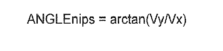
- Thus, the angle and speed of the
steerable nips - To handle the full high spectrum from 3.5" tall to 10" tall, it is desirable to have the shortest mail piece shift upwards, and the tallest mail piece shift downwards (for a bottom to top re-justification). This reduces the maximum literal shift magnitude, reducing the maximum lateral accelerations and velocities. Ideally, the system would be set up so that the average size piece goes straight through without any shift (This would be for a 6.75" piece in this scenario). Consequently, the 3.5" tall piece would shift 3.25" upwards, while the tallest piece shifts 3.25" downward. However, since this same justifier 4 would be used directly after the meter, and it is desirable not to have nips run over the freshly printed indicia (which would smear the image), the maximum vertical shift for the 3.5" piece is limited to 2". This provides a 1.5" 'clear zone' where the
mail piece 1 is not touched so as to not smear the freshly printed indicia. This requires a downward shift of 4.5" for the tallest mail piece. This is all for a bottom to top registration shift. For a top to bottom registration shift (as it would be after the meter), the shift magnitudes would be the same, but the directions would be reversed. - In the preferred embodiment, the distance from the first to last nip is 300mm. In a typical implantation, velocity parallel to the nips is 100 in/sec or 2.5m/s. For a c5 envelope, the shift displacement will be roughly 2 inches. This displacement can be achieved in about 70ms over the distance of the justifier 4. These speeds would allow processing of up to 26,000 mail pieces per hour.
- In an alternate embodiment, instead of connecting
links steering arms motor 6 and the steerable nips 13, 15, a timing belt can be used. Instead of the steeringarms motor 6 and the steering assemblies to transfer the motion. This offers the benefit of increased range of travel. - To further increase travel, instead of the current
serpentine belt 8 arrangement to power thedrive roller 13, an arrangement of bevel and spur gears can be used to transfer motion from a rigidly mounted motor the drive roller mounted inside the steering assembly. This design gives the steerable assembly the ability to rotate a full 360 degrees, without any mechanical constraints. - Although the steerable nip assemblies described herein are being used in this case to impart a lateral shift of the
incoming mail 1 to allow metering, this assembly could be used, with slight modifications, in other areas of a paper handling device to impart a variable lateral offset, or a direction change of the mail, such as a right angle turn. -
Figure 5 depicts the respective motion of differentsized envelopes exemplary justifier 22. As shown inFig. 5 , the envelopes travel frombottom justification 20 totop justification 21. Forlarger envelope 1A, it can be seen that thenips top justification wall 21. Conversely,smaller envelop 1B will be angled upward towards the justification wall. - An alternative variation of the justifier 4' solves the problem by having a drive nip which is mounted on a linear slide nip
assembly 30. (SeeFigs. 6-9 ) As a mailpiece enters thenip pair assembly 30 will slide a given displacement laterally to shift the mailpiece from bottom justified to top justified. The drive nip 36 and the sliding motion are created by a novel belt and motor arrangement, as seen inFig. 8 and further described below - The nip is comprised of a pair of rigid
lower drive rollers 36 and a pair of compliant upperidler rollers 33. Each set of rollers is rigidly coupled together, to increases the paper's resistance to skew as the assembly slides laterally. Thelower drive rollers 36 have a high friction coating on the driving surface, to increase the grip on the paper. - Mounted on the sliding assembly are a set of
bevel gears 37, which transmit power from adrive timing pulley 44 to thedrive rollers 36. Also, mounted on the slidingassembly 30 is anidler timing pulley 34, which moves with the slidingassembly 30. - Mounted to the fixed
baseplate 40, are twoservomotors belt idlers 43. Asingle timing belt 44 wraps around the two servomotor pulleys 41, 42 the four fixedbelt idlers 43, and the two timing pulleys 34, 35 on the underside of the slidingassembly 30. - The
belt 44 is arranged as such so that the belt length stays constant as the slider is moved through its travel. Referring toFig. 9C , as theslider mechanism 30, along with the timing drivepulley 35 and timingidler pulley 34 is moved upwards, the belt spans 'A' and 'B' increase in length, while spans 'C' and 'D' shorten. By having these spans parallel to theslider 30 direction, thebelt 44 length stays constant. Travel in the opposite direction is depicted inFig. 9B . - With the following arrangement, the system has two degrees of freedom, one in the slider movement, and one in the nip rotation. The two
servo motors - Nip rotation is accomplished by running both
motors Fig. 9A . This keeps the lengths of spans A,B,C, and D constant, which keeps theslider 30 stationary, while rotating the timing drivepulley 35. This, in turn, powers the bevel gears 37, which rotates thenips -
Slider 30 motion is accomplished by running bothmotors pulley 35 stationary, but causes spans A, B, C, and D to change in length. The magnitude of the velocity of theslider 30 is directly proportional to the difference between the two motors. - It is desired during normal operation to have the
nip pair slider 30 will translate to induce a lateral shift in the mail. The magnitude of the sliding move will be based on the height of the incoming mailpiece. - To accomplish this, both
motors - To handle the full high spectrum from 3.5" tall to 7.25" tall, it is desirable to have the shortest mailpiece shift upwards, and the tallest mailpiece shift downwards (for a bottom to top re-justification). This reduces the maximum lateral shift magnitude, reducing the maximum lateral accelerations and velocities. Ideally, the system would be set up so that the average size piece goes straight through without any shift. (This would be for a 5.125" piece in this scenario). Consequently, the 3.5" tall piece would shift 1.875" upwards, while the tallest piece shifts down 1.875. This is all for a bottom to top registration shift. For a top to bottom registration shift (as it would be after the meter), the shift magnitudes would be the same, but the directions would be reversed.
- Although the invention has been described with respect to preferred embodiments thereof, it will be understood by those skilled in the art that the foregoing and various other changes, omissions and deviations in the form and detail thereof may be made without departing from the scope of this invention.
Claims (20)
- A justifier apparatus for switching a transported item (1A, 1B) from bottom justification to top justification, or from top justification to bottom justification, the apparatus comprising:a first transport configured for transporting variable sized items justified along a first side (20);a justifier module (22) downstream of the first transport, the justifier module configured to transport an item in a downstream direction and having a lateral displacement mechanism for moving the item from justification along the first side (20) to justification along a second side (21), opposite from the first side;a controller configured for controlling the lateral displacement mechanism to laterally displace the item (1A, 1B), from justification on the first side (20) to justification on the second side (21), as a function of a lateral height of the item; anda second transport downstream of the justifier module for transporting variable sized items (1A, 1B) justified along the second side (21).
- The justifier apparatus of claim 1 further comprising a second justifier module downstream of the second transport configured to transport the item in the downstream direction and having a second lateral displacement mechanism for moving the item from justification along the second side to justification along the first side; and wherein the controller is configured to control the second lateral displacement mechanism to laterally displace the item for justification on the first side as a function of the lateral height of the item.
- The justifier apparatus of claim 1 or 2 wherein the second transport is comprised of a postage printing device.
- The justifier apparatus of claim 3 wherein the controller is configured to control the second lateral displacement mechanism to avoid subjecting a printed postage mark on the item to smearing by any mechanical transport elements of the second justifier module.
- The justifier apparatus of any preceding claim further comprising a sensor for detecting the lateral high of items, the sensor coupled to the controller and providing item height information to the controller.
- The justifier apparatus of any preceding claim wherein the justifier module comprises one or more sets of steerable nips (13, 15), controllable by the controller, and wherein the controller is configured to steer the steerable nips (13, 15) at an angle to achieve lateral displacement of the item for switching edge justification within the justifier module.
- The justifier apparatus of claim 6 wherein the speed of the steerable nips (13, 15) is controllable by the controller so as to maintain a constant velocity in the downstream direction while adding a lateral velocity component for the lateral displacement.
- The justifier apparatus of claim 7 wherein the steerable nips (13, 15) are controllable by the controller to be parallel to the downstream direction when the item initially enters the justifier module, to be turned at the angle after the item is within control of the steerable nips, and to be returned to parallel with the downstream direction prior to transferring the item to the second transport.
- The justifier apparatus of claim 6 configured to handle a range of items having lateral heights from small to large, and wherein the steerable nips (13, 15) are configured to be steerable towards and away from the second side (21), and the controller is configured to control the steerable nips (13, 15) such that small items are steered in a direction towards the second side (21) to achieve justification with the second side, and large items are steered in a direction towards the first side (20) to achieve justification with the second side (21).
- The justifier apparatus of claim 9 wherein the steerable nips (13, 15) are laterally positioned relative to a transport path of the first transport to receive all items having lateral heights from small to large.
- The justifier apparatus of any of claims 1 to 5 wherein the justifier module (22) is comprised of a non-steerable nip assembly (33, 36) configured to transport items in the downstream direction, wherein the non-steerable nip assembly (33, 36) is configured to slide laterally and the controller is configured to laterally displace the item by laterally moving the non-steerable nip assembly.
- An edge justification method for switching a transported item (1A, 1B) from bottom justification to top justification, or from top justification to bottom justification, the method comprising:transporting variable sized items (1A, 1B) justified along a first side (20) of a first transport;receiving a transported item (1A, 1B) from the first transport in a justifier module (22) downstream of the first transport,transport the item (1A, 1B) in a downstream direction in the justifier module (22);laterally displacing the item in the justifier module (22) from justification along the first side (20) to justification along a second side (21), opposite from the first side, while transporting the item (1A, 1B) in the downstream direction,controlling lateral displacement, for justification on the first side (20) to justification on the second side (21), as a function of a lateral height of the item; andreceiving the item (1A, 1B) in a second transport downstream of the justifier module (22) for transporting variable sized items justified along the second side.
- The edge justification method of claim 12 further including steps of:receiving the item (1A, 1B) at a second justifier module downstream of the second transport and transporting the item in the downstream direction; andperforming a second lateral displacement on the item (1A, 1 B) from justification along the second side (21) back to justification along the first side (20), said second lateral displacement being as a function of the lateral height of the item.
- The edge justification method of claim 13 further comprising the step of printing a postage indicia on the item while it is being transported in the second transport.
- The edge justification method of claim 14 further comprising controlling the second lateral displacement to avoid subjecting a printed postage mark on the item to smearing by any mechanical transport elements.
- The edge justification method of any one of claims 12 to 15 wherein the justifier module comprises one or more sets of steerable nips (13, 15) and further comprising the step of steering the steerable nips (13, 15) at an angle to achieve lateral displacement of the item for switching edge justification within the justifier module.
- The edge justification method of claim 16 further comprising controlling the speed of the steerable nips (13, 15) so as to maintain a constant velocity in the downstream direction while adding a lateral velocity component for the lateral displacement.
- The edge justification method of claim 16 or 17 further comprising controlling the steerable nips (13, 15) to be parallel to the downstream direction when the item initially enters the justifier module (22), to be turned at the angle after the item is within control of the steerable nips (13, 15), and to be returned to parallel with the downstream direction prior to transferring the item to the second transport.
- The edge justification method of any one of claims 16 to 18 for handling a range of items having lateral heights from small to large, and wherein the steerable nips (13, 15) are configured to be steerable towards and away from the second side (21), further including a step of controlling the steerable nips (13, 15) such that small items are steered in a direction towards the second side (21) to achieve justification with the second side (21), and large items are steered in a direction towards the first side (20) to achieve justification with the second side (21).
- The edge justification method of any one of claims 12 to 15 wherein the justifier module is comprised of a non-steerable nip assembly (33, 36) configured to transport items in the downstream direction, wherein the non-steerable nip assembly (33, 36) is configured to slide laterally and further including a step of laterally displacing the item by laterally moving the non-steerable nip assembly while the item is within the non-steerable nip assembly.
Applications Claiming Priority (2)
| Application Number | Priority Date | Filing Date | Title |
|---|---|---|---|
| US38147010P | 2010-09-10 | 2010-09-10 | |
| US13/226,720 US8800748B2 (en) | 2010-09-10 | 2011-09-07 | Method and apparatus for edge justification of mail items |
Publications (2)
| Publication Number | Publication Date |
|---|---|
| EP2428283A1 true EP2428283A1 (en) | 2012-03-14 |
| EP2428283B1 EP2428283B1 (en) | 2013-04-10 |
Family
ID=44677680
Family Applications (1)
| Application Number | Title | Priority Date | Filing Date |
|---|---|---|---|
| EP11180700.4A Not-in-force EP2428283B1 (en) | 2010-09-10 | 2011-09-09 | Method and apparatus for edge justification of mail items |
Country Status (2)
| Country | Link |
|---|---|
| US (1) | US8800748B2 (en) |
| EP (1) | EP2428283B1 (en) |
Families Citing this family (2)
| Publication number | Priority date | Publication date | Assignee | Title |
|---|---|---|---|---|
| KR102099107B1 (en) * | 2019-07-09 | 2020-04-09 | 화동하이테크 주식회사 | Diverter for Transferring Conveyor |
| JP2025183534A (en) * | 2024-06-05 | 2025-12-17 | キヤノン株式会社 | Sheet conveying device, image forming apparatus, and image forming system |
Citations (9)
| Publication number | Priority date | Publication date | Assignee | Title |
|---|---|---|---|---|
| DE1113423B (en) * | 1959-03-18 | 1961-08-31 | Telefunken Patent | Device for aligning letters in an upright conveyor system |
| US4775143A (en) | 1985-12-12 | 1988-10-04 | Pitney Bowes Inc. | Deskewing device for mailing machine |
| US6102391A (en) | 1998-05-15 | 2000-08-15 | Pitney Bowes Inc. | Right angle transfer apparatus |
| DE10115906A1 (en) * | 2001-03-30 | 2002-10-17 | Siemens Ag | Conveyor to transport and align objects, esp. for letter distribution plant has twisted conveyor belt with belt guide, and rollers fastened to it |
| EP1312427A1 (en) * | 2001-11-14 | 2003-05-21 | Siemens Schweiz AG | Method and installation for sorting mail pieces with an acceleration roller |
| US6715755B2 (en) | 2001-10-18 | 2004-04-06 | Pitney Bowes Inc. | Deterministic aligner for an output inserter system |
| US7416183B2 (en) | 2005-06-06 | 2008-08-26 | Pitney Bowes Inc. | Postal weighing platform with integrated feeding and deskewing functions |
| US7516904B2 (en) | 2004-05-03 | 2009-04-14 | Veritec, Inc. | Methods for encoding and decoding information |
| US7614551B2 (en) | 2005-10-31 | 2009-11-10 | Veritec, Inc. | Method and system for securely encoding and decoding biometric data into a memory device using a two dimensional symbol |
Family Cites Families (15)
| Publication number | Priority date | Publication date | Assignee | Title |
|---|---|---|---|---|
| US3148877A (en) * | 1962-02-12 | 1964-09-15 | Internat Business Macines Corp | Sheet driving and aligning mechanism |
| US3910402A (en) * | 1973-03-12 | 1975-10-07 | Dean Research Corp | Routing and conveying apparatus |
| US4621801A (en) * | 1984-12-06 | 1986-11-11 | Xerox Corporation | Document edge registration system |
| DE3446805A1 (en) * | 1984-12-21 | 1986-07-03 | Mannesmann AG, 4000 Düsseldorf | CONVEYOR |
| US4836527A (en) * | 1988-04-18 | 1989-06-06 | Xerox Corporation | Side edge registration system |
| US4919318A (en) * | 1988-04-18 | 1990-04-24 | Xerox Corporation | Swing arm roller speed differential web tracking system |
| US5219159A (en) * | 1992-06-01 | 1993-06-15 | Xerox Corporation | Translating nip registration device |
| US5460362A (en) * | 1994-07-11 | 1995-10-24 | Pitney Bowes Inc. | Mailing machine including modifiable mailpiece drive |
| US5697609A (en) * | 1996-06-26 | 1997-12-16 | Xerox Corporation | Lateral sheet pre-registration device |
| JP3186618B2 (en) * | 1996-12-12 | 2001-07-11 | 富士ゼロックス株式会社 | Paper aligning apparatus and image forming apparatus having the same |
| JP3769913B2 (en) * | 1997-12-26 | 2006-04-26 | 富士ゼロックス株式会社 | Sheet alignment apparatus and image forming apparatus provided with the same |
| US6137989A (en) * | 1998-04-15 | 2000-10-24 | Xerox Corporation | Sensor array and method to correct top edge misregistration |
| JP4601792B2 (en) * | 2000-09-14 | 2010-12-22 | 株式会社東芝 | Paper sheet processing equipment |
| US6942214B2 (en) * | 2000-12-27 | 2005-09-13 | Pitney Bowes Inc. | Mail registration and feeding apparatus |
| US7845635B2 (en) * | 2008-11-19 | 2010-12-07 | Xerox Corporation | Translating registration nip systems for different width media sheets |
-
2011
- 2011-09-07 US US13/226,720 patent/US8800748B2/en active Active
- 2011-09-09 EP EP11180700.4A patent/EP2428283B1/en not_active Not-in-force
Patent Citations (9)
| Publication number | Priority date | Publication date | Assignee | Title |
|---|---|---|---|---|
| DE1113423B (en) * | 1959-03-18 | 1961-08-31 | Telefunken Patent | Device for aligning letters in an upright conveyor system |
| US4775143A (en) | 1985-12-12 | 1988-10-04 | Pitney Bowes Inc. | Deskewing device for mailing machine |
| US6102391A (en) | 1998-05-15 | 2000-08-15 | Pitney Bowes Inc. | Right angle transfer apparatus |
| DE10115906A1 (en) * | 2001-03-30 | 2002-10-17 | Siemens Ag | Conveyor to transport and align objects, esp. for letter distribution plant has twisted conveyor belt with belt guide, and rollers fastened to it |
| US6715755B2 (en) | 2001-10-18 | 2004-04-06 | Pitney Bowes Inc. | Deterministic aligner for an output inserter system |
| EP1312427A1 (en) * | 2001-11-14 | 2003-05-21 | Siemens Schweiz AG | Method and installation for sorting mail pieces with an acceleration roller |
| US7516904B2 (en) | 2004-05-03 | 2009-04-14 | Veritec, Inc. | Methods for encoding and decoding information |
| US7416183B2 (en) | 2005-06-06 | 2008-08-26 | Pitney Bowes Inc. | Postal weighing platform with integrated feeding and deskewing functions |
| US7614551B2 (en) | 2005-10-31 | 2009-11-10 | Veritec, Inc. | Method and system for securely encoding and decoding biometric data into a memory device using a two dimensional symbol |
Also Published As
| Publication number | Publication date |
|---|---|
| US20120063875A1 (en) | 2012-03-15 |
| EP2428283B1 (en) | 2013-04-10 |
| US8800748B2 (en) | 2014-08-12 |
Similar Documents
| Publication | Publication Date | Title |
|---|---|---|
| US5180154A (en) | Method and apparatus for changing the direction of motion of flat articles | |
| AU2009288644B2 (en) | Conveying apparatus for envelopes and related methods | |
| US8356967B2 (en) | Stacker, stacking system or assembly and method for stacking | |
| US20120098184A1 (en) | System and method for inline cutting and stacking of sheets for formation of books | |
| US6817608B2 (en) | Method and apparatus for stacking mailpieces in consecutive order | |
| US20090139839A1 (en) | Electrodynamic propulsion system for conveying sheet material | |
| US8418834B2 (en) | Prefeeding corrugated boards to box finishing machines | |
| CN107265150A (en) | Bank note conveyer | |
| US5368287A (en) | Ninety degree turn-up apparatus | |
| EP0174443B1 (en) | Insertion machines | |
| US5618375A (en) | Envelope processing unit | |
| EP3241790B1 (en) | Sheet stacker | |
| EP2428283B1 (en) | Method and apparatus for edge justification of mail items | |
| US9555991B2 (en) | Rotating device for flat products or for a stack thereof | |
| US20100126826A1 (en) | Package diverting mechanism for conveyor systems | |
| US6082733A (en) | Sorting device in a conveyor of plate-like workpieces | |
| CN210286073U (en) | Carton paging machine of adjustable position | |
| US5056772A (en) | Paper rotating table | |
| JPH01256447A (en) | Device for changing position of print arranged in scaly row | |
| FI93539C (en) | Device for aligning glass sheets during transport on a roller conveyor | |
| CN101121354A (en) | Process and apparatus for producing printed matter made of several adhesively bound printing products | |
| US7971865B2 (en) | Inserting apparatus for discrete objects into envelopes and related methods | |
| US20100013142A1 (en) | Transport for singulating items | |
| CN220448882U (en) | Automatic change commodity circulation letter sorting equipment | |
| CN212831356U (en) | Mixed package separation device |
Legal Events
| Date | Code | Title | Description |
|---|---|---|---|
| AK | Designated contracting states |
Kind code of ref document: A1 Designated state(s): AL AT BE BG CH CY CZ DE DK EE ES FI FR GB GR HR HU IE IS IT LI LT LU LV MC MK MT NL NO PL PT RO RS SE SI SK SM TR |
|
| AX | Request for extension of the european patent |
Extension state: BA ME |
|
| PUAI | Public reference made under article 153(3) epc to a published international application that has entered the european phase |
Free format text: ORIGINAL CODE: 0009012 |
|
| 17P | Request for examination filed |
Effective date: 20120725 |
|
| GRAP | Despatch of communication of intention to grant a patent |
Free format text: ORIGINAL CODE: EPIDOSNIGR1 |
|
| RIC1 | Information provided on ipc code assigned before grant |
Ipc: B07C 1/06 20060101ALI20120928BHEP Ipc: G07B 17/00 20060101ALI20120928BHEP Ipc: B07C 1/00 20060101AFI20120928BHEP |
|
| GRAS | Grant fee paid |
Free format text: ORIGINAL CODE: EPIDOSNIGR3 |
|
| GRAA | (expected) grant |
Free format text: ORIGINAL CODE: 0009210 |
|
| AK | Designated contracting states |
Kind code of ref document: B1 Designated state(s): AL AT BE BG CH CY CZ DE DK EE ES FI FR GB GR HR HU IE IS IT LI LT LU LV MC MK MT NL NO PL PT RO RS SE SI SK SM TR |
|
| REG | Reference to a national code |
Ref country code: GB Ref legal event code: FG4D |
|
| REG | Reference to a national code |
Ref country code: AT Ref legal event code: REF Ref document number: 605694 Country of ref document: AT Kind code of ref document: T Effective date: 20130415 Ref country code: CH Ref legal event code: EP |
|
| REG | Reference to a national code |
Ref country code: IE Ref legal event code: FG4D |
|
| REG | Reference to a national code |
Ref country code: DE Ref legal event code: R096 Ref document number: 602011001304 Country of ref document: DE Effective date: 20130606 |
|
| PG25 | Lapsed in a contracting state [announced via postgrant information from national office to epo] |
Ref country code: SI Free format text: LAPSE BECAUSE OF FAILURE TO SUBMIT A TRANSLATION OF THE DESCRIPTION OR TO PAY THE FEE WITHIN THE PRESCRIBED TIME-LIMIT Effective date: 20130410 |
|
| REG | Reference to a national code |
Ref country code: AT Ref legal event code: MK05 Ref document number: 605694 Country of ref document: AT Kind code of ref document: T Effective date: 20130410 |
|
| REG | Reference to a national code |
Ref country code: NL Ref legal event code: VDEP Effective date: 20130410 Ref country code: LT Ref legal event code: MG4D |
|
| PG25 | Lapsed in a contracting state [announced via postgrant information from national office to epo] |
Ref country code: SE Free format text: LAPSE BECAUSE OF FAILURE TO SUBMIT A TRANSLATION OF THE DESCRIPTION OR TO PAY THE FEE WITHIN THE PRESCRIBED TIME-LIMIT Effective date: 20130410 Ref country code: ES Free format text: LAPSE BECAUSE OF FAILURE TO SUBMIT A TRANSLATION OF THE DESCRIPTION OR TO PAY THE FEE WITHIN THE PRESCRIBED TIME-LIMIT Effective date: 20130721 Ref country code: PT Free format text: LAPSE BECAUSE OF FAILURE TO SUBMIT A TRANSLATION OF THE DESCRIPTION OR TO PAY THE FEE WITHIN THE PRESCRIBED TIME-LIMIT Effective date: 20130812 Ref country code: FI Free format text: LAPSE BECAUSE OF FAILURE TO SUBMIT A TRANSLATION OF THE DESCRIPTION OR TO PAY THE FEE WITHIN THE PRESCRIBED TIME-LIMIT Effective date: 20130410 Ref country code: BE Free format text: LAPSE BECAUSE OF FAILURE TO SUBMIT A TRANSLATION OF THE DESCRIPTION OR TO PAY THE FEE WITHIN THE PRESCRIBED TIME-LIMIT Effective date: 20130410 Ref country code: NO Free format text: LAPSE BECAUSE OF FAILURE TO SUBMIT A TRANSLATION OF THE DESCRIPTION OR TO PAY THE FEE WITHIN THE PRESCRIBED TIME-LIMIT Effective date: 20130710 Ref country code: LT Free format text: LAPSE BECAUSE OF FAILURE TO SUBMIT A TRANSLATION OF THE DESCRIPTION OR TO PAY THE FEE WITHIN THE PRESCRIBED TIME-LIMIT Effective date: 20130410 Ref country code: AT Free format text: LAPSE BECAUSE OF FAILURE TO SUBMIT A TRANSLATION OF THE DESCRIPTION OR TO PAY THE FEE WITHIN THE PRESCRIBED TIME-LIMIT Effective date: 20130410 Ref country code: IS Free format text: LAPSE BECAUSE OF FAILURE TO SUBMIT A TRANSLATION OF THE DESCRIPTION OR TO PAY THE FEE WITHIN THE PRESCRIBED TIME-LIMIT Effective date: 20130810 Ref country code: NL Free format text: LAPSE BECAUSE OF FAILURE TO SUBMIT A TRANSLATION OF THE DESCRIPTION OR TO PAY THE FEE WITHIN THE PRESCRIBED TIME-LIMIT Effective date: 20130410 Ref country code: GR Free format text: LAPSE BECAUSE OF FAILURE TO SUBMIT A TRANSLATION OF THE DESCRIPTION OR TO PAY THE FEE WITHIN THE PRESCRIBED TIME-LIMIT Effective date: 20130711 |
|
| PG25 | Lapsed in a contracting state [announced via postgrant information from national office to epo] |
Ref country code: HR Free format text: LAPSE BECAUSE OF FAILURE TO SUBMIT A TRANSLATION OF THE DESCRIPTION OR TO PAY THE FEE WITHIN THE PRESCRIBED TIME-LIMIT Effective date: 20130410 Ref country code: LV Free format text: LAPSE BECAUSE OF FAILURE TO SUBMIT A TRANSLATION OF THE DESCRIPTION OR TO PAY THE FEE WITHIN THE PRESCRIBED TIME-LIMIT Effective date: 20130410 Ref country code: BG Free format text: LAPSE BECAUSE OF FAILURE TO SUBMIT A TRANSLATION OF THE DESCRIPTION OR TO PAY THE FEE WITHIN THE PRESCRIBED TIME-LIMIT Effective date: 20130710 Ref country code: CY Free format text: LAPSE BECAUSE OF FAILURE TO SUBMIT A TRANSLATION OF THE DESCRIPTION OR TO PAY THE FEE WITHIN THE PRESCRIBED TIME-LIMIT Effective date: 20130410 Ref country code: PL Free format text: LAPSE BECAUSE OF FAILURE TO SUBMIT A TRANSLATION OF THE DESCRIPTION OR TO PAY THE FEE WITHIN THE PRESCRIBED TIME-LIMIT Effective date: 20130410 Ref country code: RS Free format text: LAPSE BECAUSE OF FAILURE TO SUBMIT A TRANSLATION OF THE DESCRIPTION OR TO PAY THE FEE WITHIN THE PRESCRIBED TIME-LIMIT Effective date: 20130410 |
|
| PG25 | Lapsed in a contracting state [announced via postgrant information from national office to epo] |
Ref country code: EE Free format text: LAPSE BECAUSE OF FAILURE TO SUBMIT A TRANSLATION OF THE DESCRIPTION OR TO PAY THE FEE WITHIN THE PRESCRIBED TIME-LIMIT Effective date: 20130410 Ref country code: DK Free format text: LAPSE BECAUSE OF FAILURE TO SUBMIT A TRANSLATION OF THE DESCRIPTION OR TO PAY THE FEE WITHIN THE PRESCRIBED TIME-LIMIT Effective date: 20130410 Ref country code: SK Free format text: LAPSE BECAUSE OF FAILURE TO SUBMIT A TRANSLATION OF THE DESCRIPTION OR TO PAY THE FEE WITHIN THE PRESCRIBED TIME-LIMIT Effective date: 20130410 Ref country code: CZ Free format text: LAPSE BECAUSE OF FAILURE TO SUBMIT A TRANSLATION OF THE DESCRIPTION OR TO PAY THE FEE WITHIN THE PRESCRIBED TIME-LIMIT Effective date: 20130410 |
|
| PLBE | No opposition filed within time limit |
Free format text: ORIGINAL CODE: 0009261 |
|
| STAA | Information on the status of an ep patent application or granted ep patent |
Free format text: STATUS: NO OPPOSITION FILED WITHIN TIME LIMIT |
|
| PG25 | Lapsed in a contracting state [announced via postgrant information from national office to epo] |
Ref country code: IT Free format text: LAPSE BECAUSE OF FAILURE TO SUBMIT A TRANSLATION OF THE DESCRIPTION OR TO PAY THE FEE WITHIN THE PRESCRIBED TIME-LIMIT Effective date: 20130410 Ref country code: RO Free format text: LAPSE BECAUSE OF FAILURE TO SUBMIT A TRANSLATION OF THE DESCRIPTION OR TO PAY THE FEE WITHIN THE PRESCRIBED TIME-LIMIT Effective date: 20130410 |
|
| 26N | No opposition filed |
Effective date: 20140113 |
|
| REG | Reference to a national code |
Ref country code: DE Ref legal event code: R097 Ref document number: 602011001304 Country of ref document: DE Effective date: 20140113 |
|
| PG25 | Lapsed in a contracting state [announced via postgrant information from national office to epo] |
Ref country code: MC Free format text: LAPSE BECAUSE OF FAILURE TO SUBMIT A TRANSLATION OF THE DESCRIPTION OR TO PAY THE FEE WITHIN THE PRESCRIBED TIME-LIMIT Effective date: 20130410 |
|
| REG | Reference to a national code |
Ref country code: IE Ref legal event code: MM4A |
|
| PG25 | Lapsed in a contracting state [announced via postgrant information from national office to epo] |
Ref country code: IE Free format text: LAPSE BECAUSE OF NON-PAYMENT OF DUE FEES Effective date: 20130909 |
|
| REG | Reference to a national code |
Ref country code: CH Ref legal event code: PL |
|
| PG25 | Lapsed in a contracting state [announced via postgrant information from national office to epo] |
Ref country code: SM Free format text: LAPSE BECAUSE OF FAILURE TO SUBMIT A TRANSLATION OF THE DESCRIPTION OR TO PAY THE FEE WITHIN THE PRESCRIBED TIME-LIMIT Effective date: 20130410 |
|
| PG25 | Lapsed in a contracting state [announced via postgrant information from national office to epo] |
Ref country code: MT Free format text: LAPSE BECAUSE OF FAILURE TO SUBMIT A TRANSLATION OF THE DESCRIPTION OR TO PAY THE FEE WITHIN THE PRESCRIBED TIME-LIMIT Effective date: 20130410 Ref country code: TR Free format text: LAPSE BECAUSE OF FAILURE TO SUBMIT A TRANSLATION OF THE DESCRIPTION OR TO PAY THE FEE WITHIN THE PRESCRIBED TIME-LIMIT Effective date: 20130410 |
|
| PG25 | Lapsed in a contracting state [announced via postgrant information from national office to epo] |
Ref country code: CH Free format text: LAPSE BECAUSE OF NON-PAYMENT OF DUE FEES Effective date: 20140930 Ref country code: LU Free format text: LAPSE BECAUSE OF NON-PAYMENT OF DUE FEES Effective date: 20130909 Ref country code: MK Free format text: LAPSE BECAUSE OF FAILURE TO SUBMIT A TRANSLATION OF THE DESCRIPTION OR TO PAY THE FEE WITHIN THE PRESCRIBED TIME-LIMIT Effective date: 20130410 Ref country code: HU Free format text: LAPSE BECAUSE OF FAILURE TO SUBMIT A TRANSLATION OF THE DESCRIPTION OR TO PAY THE FEE WITHIN THE PRESCRIBED TIME-LIMIT; INVALID AB INITIO Effective date: 20110909 Ref country code: LI Free format text: LAPSE BECAUSE OF NON-PAYMENT OF DUE FEES Effective date: 20140930 |
|
| REG | Reference to a national code |
Ref country code: FR Ref legal event code: PLFP Year of fee payment: 6 |
|
| REG | Reference to a national code |
Ref country code: FR Ref legal event code: PLFP Year of fee payment: 7 |
|
| REG | Reference to a national code |
Ref country code: FR Ref legal event code: PLFP Year of fee payment: 8 |
|
| PG25 | Lapsed in a contracting state [announced via postgrant information from national office to epo] |
Ref country code: AL Free format text: LAPSE BECAUSE OF FAILURE TO SUBMIT A TRANSLATION OF THE DESCRIPTION OR TO PAY THE FEE WITHIN THE PRESCRIBED TIME-LIMIT Effective date: 20130410 |
|
| REG | Reference to a national code |
Ref country code: DE Ref legal event code: R082 Ref document number: 602011001304 Country of ref document: DE Representative=s name: HOFFMANN - EITLE PATENT- UND RECHTSANWAELTE PA, DE Ref country code: DE Ref legal event code: R081 Ref document number: 602011001304 Country of ref document: DE Owner name: DMT SOLUTIONS GLOBAL CORP. (N.D.GES.D. STAATES, US Free format text: FORMER OWNER: PITNEY BOWES, INC., STAMFORD, CONN., US |
|
| PGFP | Annual fee paid to national office [announced via postgrant information from national office to epo] |
Ref country code: FR Payment date: 20190925 Year of fee payment: 9 |
|
| REG | Reference to a national code |
Ref country code: GB Ref legal event code: 732E Free format text: REGISTERED BETWEEN 20191128 AND 20191204 |
|
| PGFP | Annual fee paid to national office [announced via postgrant information from national office to epo] |
Ref country code: GB Payment date: 20190927 Year of fee payment: 9 |
|
| PGFP | Annual fee paid to national office [announced via postgrant information from national office to epo] |
Ref country code: DE Payment date: 20190927 Year of fee payment: 9 |
|
| REG | Reference to a national code |
Ref country code: DE Ref legal event code: R119 Ref document number: 602011001304 Country of ref document: DE |
|
| GBPC | Gb: european patent ceased through non-payment of renewal fee |
Effective date: 20200909 |
|
| PG25 | Lapsed in a contracting state [announced via postgrant information from national office to epo] |
Ref country code: DE Free format text: LAPSE BECAUSE OF NON-PAYMENT OF DUE FEES Effective date: 20210401 Ref country code: FR Free format text: LAPSE BECAUSE OF NON-PAYMENT OF DUE FEES Effective date: 20200930 |
|
| PG25 | Lapsed in a contracting state [announced via postgrant information from national office to epo] |
Ref country code: GB Free format text: LAPSE BECAUSE OF NON-PAYMENT OF DUE FEES Effective date: 20200909 |