EP2426897A2 - Docking station for portable communication device - Google Patents
Docking station for portable communication device Download PDFInfo
- Publication number
- EP2426897A2 EP2426897A2 EP20110179481 EP11179481A EP2426897A2 EP 2426897 A2 EP2426897 A2 EP 2426897A2 EP 20110179481 EP20110179481 EP 20110179481 EP 11179481 A EP11179481 A EP 11179481A EP 2426897 A2 EP2426897 A2 EP 2426897A2
- Authority
- EP
- European Patent Office
- Prior art keywords
- portable communication
- communication device
- docking station
- guide portion
- body portion
- Prior art date
- Legal status (The legal status is an assumption and is not a legal conclusion. Google has not performed a legal analysis and makes no representation as to the accuracy of the status listed.)
- Granted
Links
Images


Classifications
-
- H—ELECTRICITY
- H04—ELECTRIC COMMUNICATION TECHNIQUE
- H04M—TELEPHONIC COMMUNICATION
- H04M1/00—Substation equipment, e.g. for use by subscribers
- H04M1/02—Constructional features of telephone sets
- H04M1/04—Supports for telephone transmitters or receivers
-
- G—PHYSICS
- G06—COMPUTING; CALCULATING OR COUNTING
- G06F—ELECTRIC DIGITAL DATA PROCESSING
- G06F1/00—Details not covered by groups G06F3/00 - G06F13/00 and G06F21/00
- G06F1/16—Constructional details or arrangements
- G06F1/1613—Constructional details or arrangements for portable computers
- G06F1/1632—External expansion units, e.g. docking stations
-
- H—ELECTRICITY
- H02—GENERATION; CONVERSION OR DISTRIBUTION OF ELECTRIC POWER
- H02J—CIRCUIT ARRANGEMENTS OR SYSTEMS FOR SUPPLYING OR DISTRIBUTING ELECTRIC POWER; SYSTEMS FOR STORING ELECTRIC ENERGY
- H02J7/00—Circuit arrangements for charging or depolarising batteries or for supplying loads from batteries
- H02J7/0042—Circuit arrangements for charging or depolarising batteries or for supplying loads from batteries characterised by the mechanical construction
- H02J7/0044—Circuit arrangements for charging or depolarising batteries or for supplying loads from batteries characterised by the mechanical construction specially adapted for holding portable devices containing batteries
Definitions
- the present invention relates to a docking station for a portable communication device provided with a guide portion that is formed to fit various exterior shapes of the portable communication device and to be detachable coupled to the docking station.
- portable communication devices enable wireless communication while the devices are being carried around.
- the portable communication devices include a hand-held phone (HHP), a cordless telephone (CT-) 2 cellular phone, a digital phone, a personal communications systems (PCS) phone, and a personal digital assistant (PDA), etc.
- the wireless terminals are typically classified into a bar type, a flip type, a folder type, and a sliding type according to their shapes.
- These portable terminals include an antenna apparatus, a data input/output device such as a touch screen, and a data transceiver.
- the portable communication device is not equipped with parts such as a local printer, a backup drive, and a mass storage device.
- the portable communication device needs a docking station for connection to other accessory parts.
- the docking station includes a hardware device and a series of connecting interfaces for engaging with external devices.
- a docking station 2 includes a slot 2a formed to fit for the shape of a portable communication device 1 and a connecting terminal 2b connecting the portable communication device 1 via the slot 2a.
- the portable communication device 1 When the portable communication device 1 is electrically connected to the slot 2a of the docking station 2, a user can use a charging device, an external memory device, a local printer, and the like. When moving to other places, the user may detach the portable communication device 1 from the slot 2a to use the portable communication device 1 in corresponding places.
- a docking station for a conventional portable communication device has a slot formed to fit for the exterior shape of the portable communication device, such that the slot cannot be used for a portable communication device having different exterior shape.
- a separate docking station having a slot formed to fit for that particular shape is required, increasing a cost of a product.
- an aspect of the present invention is to provide a docking station for a portable communication device in which is provided a guide portion that is formed to adoptively house and detachably coupled to various exterior shapes of the portable communication device, thereby making it possible to use portable communication devices having various exterior shapes through a single docking station.
- Another aspect of the present invention is to provide a docking station for a portable communication device in which is provided a cradling portion that allows portable communication devices having various exterior shapes to be directly mounted on or dismounted from a single docking station, thereby making it possible to use portable communication devices having various exterior shapes and thus improving efficiency in using a product.
- a docking station for a portable communication device.
- the docking station includes a body portion of the docking station and a guide portion which is formed to fit various exterior shapes of the portable communication device, to be detachable from the portable communication device, and to be separated from or coupled to the body portion.
- a docking station 10 for a portable communication device 1 includes a docking station having a body portion 20 and a guide portion 30.
- the body portion 20 allows the guide portion 30 coupled with the portable communication device 1 to be mounted thereon or dismounted therefrom.
- the guide portion 30 is formed to fit and house various exterior shapes of the portable communication device 1 and to be detachable from the portable communication device 1. That is, when coupled with the portable communication device 1, the guide portion 30 can be separated from or coupled to the body portion 20.
- a cradling portion 23 to allow the guide portion 30 to be mounted thereon or dismounted therefrom while supporting the guide portion 30 such that the guide portion 30 can be inclinedly cradled on the cradling portion 23 when the body portion 20 is coupled with the guide portion 30.
- the cradling portion 23 is substantially formed in a "V" shape to inclinedly cradle the guide portion 30 thereon.
- the cradling portion 23 includes a connecting terminal 23a for electric connection with an interface (not shown) included in the portable communication device 1 when coupled to the guide portion 30.
- a terminal through-hole 33 which allows the connecting terminal 23 a to pass therethrough for electric connection with the interface (not shown) of the portable communication device 1 when the portable communication device 1 is coupled with the guide portion 30.
- the guide portion 30 is formed to fit the exterior shape of the portable communication device 1, thereby allowing the portable communication device 1 to be mounted on or dismounted from the guide portion 30.
- the guide portion 30 includes a coupling portion 31 which is formed on a rear surface of the guide portion 30 to be separated from or contactly coupled with the body portion 20 through a coupling groove 21. Further, in the guide portion 30 is formed a mounting/dismounting recess 34 for allowing the portable communication device 1 to be mounted on or dismounted from the guide portion 30.
- the docking station 10 is applicable to the portable communication device 1.
- the teachings of the present invention is applicable to other portable communication devices having various exterior shapes such as a bar type, a folder type, a sliding type, a swing type, and so forth.
- examples of the portable communication device 1 according to an embodiment of the present invention may include not only mobile communication terminals operating according to communication protocols corresponding to various communication systems, but also any information communication apparatuses and multimedia apparatuses such as Portable Multimedia Players (PMPs), MP3 players, navigations, game players, notebook computers, advertising boards, TVs, digital broadcasting players, Personal Digital Assistants (PDAs), smart phones, waterproof phones, and so forth, and their application apparatuses.
- PMPs Portable Multimedia Players
- MP3 players Portable Multimedia Players
- navigations navigations
- game players Portable Multimedia Players
- notebook computers Portable Multimedia Players
- advertising boards Portable Multimedia Players
- TVs Portable Multimedia Players
- PDAs Personal Digital Assistants
- smart phones waterproof phones, and so forth, and their application apparatuses.
- the docking station 10 for the portable communication device 1 includes the body portion 20 and the guide portion 30.
- the cradling portion 23 which includes the connecting terminal 23a that electrically connects with the interface (not shown) of the portable communication device 1.
- the portable communication device 1 is coupled to the guide portion 30 and formed to fit for the exterior shape of the portable communication device 1.
- the coupling portion 31 formed in the guide portion 30 is coupled with the coupling groove 21 formed in the body portion 20.
- the guide portion 30 is coupled with the cradling portion 23 of the body portion 20 and passes the connecting terminal 23a formed in the cradling portion 23 through the terminal through-hole 33 formed in the guide portion 30, such that the connecting terminal 23a is electrically connected with the interface (not shown) of the portable communication device 1 coupled with the guide portion 30.
- the guide portion 30 with which the portable communication device 1 is coupled is inclinedly cradled on the cradling portion 23 of the body portion 20.
- the user can watch a movie and listen to the music through a display unit 1a of the portable communication device 1, and the portable communication device 1 is electrically connected with another external device (not shown) such as a charging device, an external memory device, a local printer, or the like.
- the guide portion 30 is separated from the cradling portion 23 of the body portion 20.
- the interface of the portable communication device 1 is separated from the connecting terminal 23a of the body portion 20.
- the coupling portion 31 of the guide portion 30 leaves the coupling groove 21 of the body portion 20. In this state, as shown in FIG 3 , the portable communication device 1 is separated from the guide portion 30.
- the guide portion 30 is provided to fit the exterior shape of the portable communication device 1.
- the detachable guide portion 30 for separating or coupling the portable communication device 1 from or to the docking station 10
- portable communication devices having various exterior shapes can be used through the single docking station 10.
- the cradling portion 23 for allowing portable communication devices having various exterior shapes to be directly mounted to or dismounted from the single docking station 10, the portable communication devices having various exterior shapes can be used and thus efficiency in using a product can be improved.
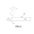
- Fig. 6 is a drawing showing other exemplary embodiment of the docking station
- the docking station (100) consists of a body portion (20) of the docking station comprising the cradling portion (23) which is detachably coupled to the portable communication device (1) which is formed to fit various exterior shape without the particular guide portion (30, shown in Figs. 2 and 4 ).
- a docking station for a portable communication device according to the present invention described above is not limited by the foregoing embodiment and drawings, and various substitutions, modifications, and changes can be made in terminals having various exterior shapes such as a sliding type, a swing type, a waterproof terminal, and so forth.
Abstract
Description
- The present invention relates to a docking station for a portable communication device provided with a guide portion that is formed to fit various exterior shapes of the portable communication device and to be detachable coupled to the docking station.
- Generally, "portable communication devices" enable wireless communication while the devices are being carried around. The portable communication devices include a hand-held phone (HHP), a cordless telephone (CT-) 2 cellular phone, a digital phone, a personal communications systems (PCS) phone, and a personal digital assistant (PDA), etc. The wireless terminals are typically classified into a bar type, a flip type, a folder type, and a sliding type according to their shapes. These portable terminals include an antenna apparatus, a data input/output device such as a touch screen, and a data transceiver.
- Unlike a Personal Computer (PC), the portable communication device is not equipped with parts such as a local printer, a backup drive, and a mass storage device. Thus, the portable communication device needs a docking station for connection to other accessory parts. The docking station includes a hardware device and a series of connecting interfaces for engaging with external devices.
- As shown in
FIG 1 , adocking station 2 includes aslot 2a formed to fit for the shape of aportable communication device 1 and a connectingterminal 2b connecting theportable communication device 1 via theslot 2a. - When the
portable communication device 1 is electrically connected to theslot 2a of thedocking station 2, a user can use a charging device, an external memory device, a local printer, and the like. When moving to other places, the user may detach theportable communication device 1 from theslot 2a to use theportable communication device 1 in corresponding places. - However, a docking station for a conventional portable communication device has a slot formed to fit for the exterior shape of the portable communication device, such that the slot cannot be used for a portable communication device having different exterior shape.
- Moreover, to use a portable communication device having different shape, a separate docking station having a slot formed to fit for that particular shape is required, increasing a cost of a product.
- Accordingly, there is a need for a single docking station that can house and accommodate portable communication devices having various exterior shapes.
- Accordingly, an aspect of the present invention is to provide a docking station for a portable communication device in which is provided a guide portion that is formed to adoptively house and detachably coupled to various exterior shapes of the portable communication device, thereby making it possible to use portable communication devices having various exterior shapes through a single docking station.
- Another aspect of the present invention is to provide a docking station for a portable communication device in which is provided a cradling portion that allows portable communication devices having various exterior shapes to be directly mounted on or dismounted from a single docking station, thereby making it possible to use portable communication devices having various exterior shapes and thus improving efficiency in using a product.
- According to an aspect of the present invention, there is provided a docking station for a portable communication device. The docking station includes a body portion of the docking station and a guide portion which is formed to fit various exterior shapes of the portable communication device, to be detachable from the portable communication device, and to be separated from or coupled to the body portion.
- The above and other features and advantages of an exemplary embodiment of the present invention will be more apparent from the following detailed description taken in conjunction with the accompanying drawings, in which:
-
FIG 1 is a perspective view showing a conventional docking station; -
FIG 2 is an exploded perspective view showing a docking station for a portable communication device according to an exemplary embodiment of the present invention; -
FIG 3 is a perspective view showing a coupled state of a docking station for a portable communication device according to an exemplary embodiment of the present invention; -
FIG 4 is a side cross-sectional view showing a pre-coupled state (or before- coupled state) of a docking station for a portable communication device according to an exemplary embodiment of the present invention; and -
FIG 5 is a side cross-sectional view showing a post-coupled state (or after- coupled state) of a docking station for a portable communication device according to an exemplary embodiment of the present invention. -
FIG 6 is a side cross-sectional view showing other exemplary embodiment of a docking station for a portable communication device according to an exemplary embodiment of the present invention. - Hereinafter, an exemplary embodiment of the present invention will be described in detail with reference to the accompanying drawings. The embodiment disclosed in the specification and structures shown in the drawings are merely exemplary ones of the present invention, and it should be understood that various variations capable of substituting for the embodiment may exist at the time of filing the application.
- Referring to
FIGs. 2 through 5 , adocking station 10 for aportable communication device 1 according to the present invention includes a docking station having abody portion 20 and aguide portion 30. Thebody portion 20 allows theguide portion 30 coupled with theportable communication device 1 to be mounted thereon or dismounted therefrom. Theguide portion 30 is formed to fit and house various exterior shapes of theportable communication device 1 and to be detachable from theportable communication device 1. That is, when coupled with theportable communication device 1, theguide portion 30 can be separated from or coupled to thebody portion 20. - As shown in
FIGs. 2 through 5 , in thebody portion 20 is formed acradling portion 23 to allow theguide portion 30 to be mounted thereon or dismounted therefrom while supporting theguide portion 30 such that theguide portion 30 can be inclinedly cradled on thecradling portion 23 when thebody portion 20 is coupled with theguide portion 30. Thecradling portion 23 is substantially formed in a "V" shape to inclinedly cradle theguide portion 30 thereon. Thecradling portion 23 includes a connectingterminal 23a for electric connection with an interface (not shown) included in theportable communication device 1 when coupled to theguide portion 30. - Further, in the
guide portion 30 is formed a terminal through-hole 33 which allows the connectingterminal 23 a to pass therethrough for electric connection with the interface (not shown) of theportable communication device 1 when theportable communication device 1 is coupled with theguide portion 30. Theguide portion 30 is formed to fit the exterior shape of theportable communication device 1, thereby allowing theportable communication device 1 to be mounted on or dismounted from theguide portion 30. - The
guide portion 30 includes acoupling portion 31 which is formed on a rear surface of theguide portion 30 to be separated from or contactly coupled with thebody portion 20 through acoupling groove 21. Further, in theguide portion 30 is formed a mounting/dismounting recess 34 for allowing theportable communication device 1 to be mounted on or dismounted from theguide portion 30. - For illustrative purposes, the
docking station 10 according to an embodiment of the present invention is applicable to theportable communication device 1. However, it should be noted that the teachings of the present invention is applicable to other portable communication devices having various exterior shapes such as a bar type, a folder type, a sliding type, a swing type, and so forth. Further, examples of theportable communication device 1 according to an embodiment of the present invention may include not only mobile communication terminals operating according to communication protocols corresponding to various communication systems, but also any information communication apparatuses and multimedia apparatuses such as Portable Multimedia Players (PMPs), MP3 players, navigations, game players, notebook computers, advertising boards, TVs, digital broadcasting players, Personal Digital Assistants (PDAs), smart phones, waterproof phones, and so forth, and their application apparatuses. - Hereinafter, a detailed description will now be made of an operating process of the
docking station 10 for theportable communication device 1 according to an embodiment of the present invention structured as described above. - As shown in
FIGs. 2 through 5 , thedocking station 10 for theportable communication device 1 includes thebody portion 20 and theguide portion 30. - In the
body portion 20 is formed thecradling portion 23 which includes the connectingterminal 23a that electrically connects with the interface (not shown) of theportable communication device 1. In this state, as shown inFIGs. 2 through 5 , when theportable communication device 1 is electrically connected to thedocking station 10, theportable communication device 1 is coupled to theguide portion 30 and formed to fit for the exterior shape of theportable communication device 1. At this time, as shown inFIGs. 4 and 5 , thecoupling portion 31 formed in theguide portion 30 is coupled with thecoupling groove 21 formed in thebody portion 20. - As shown in
FIGs. 2 and3 , theguide portion 30 is coupled with thecradling portion 23 of thebody portion 20 and passes the connectingterminal 23a formed in thecradling portion 23 through the terminal through-hole 33 formed in theguide portion 30, such that the connectingterminal 23a is electrically connected with the interface (not shown) of theportable communication device 1 coupled with theguide portion 30. - As shown in
FIG 3 , theguide portion 30 with which theportable communication device 1 is coupled is inclinedly cradled on thecradling portion 23 of thebody portion 20. In this state, the user can watch a movie and listen to the music through adisplay unit 1a of theportable communication device 1, and theportable communication device 1 is electrically connected with another external device (not shown) such as a charging device, an external memory device, a local printer, or the like. - As shown in
FIGs. 3 and4 , to separate the portableterminal communication 1 from thedocking station 10, theguide portion 30 is separated from thecradling portion 23 of thebody portion 20. In this case, the interface of theportable communication device 1 is separated from the connectingterminal 23a of thebody portion 20. At this time, as shown inFIGs. 4 and 5 , thecoupling portion 31 of theguide portion 30 leaves thecoupling groove 21 of thebody portion 20. In this state, as shown inFIG 3 , theportable communication device 1 is separated from theguide portion 30. - When the exterior of the
portable communication device 1 has another shape, theguide portion 30 is provided to fit the exterior shape of theportable communication device 1. - As such, by providing the
detachable guide portion 30 for separating or coupling theportable communication device 1 from or to thedocking station 10, portable communication devices having various exterior shapes can be used through thesingle docking station 10. Moreover, by providing thecradling portion 23 for allowing portable communication devices having various exterior shapes to be directly mounted to or dismounted from thesingle docking station 10, the portable communication devices having various exterior shapes can be used and thus efficiency in using a product can be improved. - As shown in
Fig. 6, Fig. 6 is a drawing showing other exemplary embodiment of the docking station, the docking station (100) consists of a body portion (20) of the docking station comprising the cradling portion (23) which is detachably coupled to the portable communication device (1) which is formed to fit various exterior shape without the particular guide portion (30, shown inFigs. 2 and4 ). - It will be obvious to those of ordinary skill in the art that a docking station for a portable communication device according to the present invention described above is not limited by the foregoing embodiment and drawings, and various substitutions, modifications, and changes can be made in terminals having various exterior shapes such as a sliding type, a swing type, a waterproof terminal, and so forth.
Claims (9)
- A docking station(10) for a portable communication device(1), characterized by:a body portion (20); anda guide portion(30), detachably coupled to the body portion, for adoptively housing and detachably coupled to various exterior shapes of the portable communication device.
- The docking station of claim 1, wherein the body portion(20) comprises a cradling portion(23) which allows the guide portion to be mounted thereon or dismounted therefrom, and supports the guide portion such that the guide portion is inclinedly cradled on the cradling portion when the body portion is coupled to the guide portion.
- The docking station of claim 2, wherein the cradling portion(23) is formed substantially in a V-shape, and
the cradling portion(23) comprises a connecting terminal for electric connection(23a) with an interface of the portable communication device. - The docking station of claim 3, wherein the guide portion(30) comprises a terminal through-hole(33) which allows the connecting terminal to pass therethrough.
- The docking station of claim 1, wherein the guide portion(30) further comprises a mounting/dismounting recess(34) which allows the portable communication device to be mounted on or dismounted from the guide portion.
- The docking station of claim 1, wherein the body portion (20) further includes a coupling groove (21) at one end thereof.
- The docking station of claim 1, wherein the guide portion (30) further includes a coupling portion (31) at a rear surface thereof to insertably engage with the coupling groove (21).
- A docking station(10) for a portable communication device(1), characterized by:a body portion(100) which comprises a cradling portion(23) for allowing the portable communication device having various exterior shapes to be separated from or coupled to the docking station.
- The docking station of claim 8, wherein the portable communication (1) is adoptively housed in a guide portion (30) that is detachably coupled to the body portion (20).
Applications Claiming Priority (1)
| Application Number | Priority Date | Filing Date | Title |
|---|---|---|---|
| KR2020100009334U KR200478818Y1 (en) | 2010-09-06 | 2010-09-06 | Dockong station for portable communication device |
Publications (3)
| Publication Number | Publication Date |
|---|---|
| EP2426897A2 true EP2426897A2 (en) | 2012-03-07 |
| EP2426897A3 EP2426897A3 (en) | 2013-05-01 |
| EP2426897B1 EP2426897B1 (en) | 2018-07-04 |
Family
ID=45541144
Family Applications (1)
| Application Number | Title | Priority Date | Filing Date |
|---|---|---|---|
| EP11179481.4A Not-in-force EP2426897B1 (en) | 2010-09-06 | 2011-08-31 | Docking station for portable communication device |
Country Status (4)
| Country | Link |
|---|---|
| US (1) | US9160826B2 (en) |
| EP (1) | EP2426897B1 (en) |
| KR (1) | KR200478818Y1 (en) |
| CN (1) | CN202150610U (en) |
Families Citing this family (11)
| Publication number | Priority date | Publication date | Assignee | Title |
|---|---|---|---|---|
| US20130182387A1 (en) * | 2012-01-16 | 2013-07-18 | Shadi Mere | Accessory system for portable electronic computing devices |
| US20130327904A1 (en) * | 2012-06-12 | 2013-12-12 | Albert Christal | Slotted Handheld Electronic Device Support |
| TWI498709B (en) * | 2012-06-18 | 2015-09-01 | Wistron Corp | Electronic device and supporting mechanism thereof |
| WO2014034765A1 (en) * | 2012-08-30 | 2014-03-06 | 有限会社菊川工業 | Portable terminal device accessory |
| CN102930671A (en) * | 2012-11-15 | 2013-02-13 | 无锡矽鼎科技有限公司 | Mobile payment terminal equipment |
| GB201306993D0 (en) * | 2013-04-17 | 2013-05-29 | Tomtom Int Bv | Electrical connection systems |
| TWD175064S (en) * | 2015-08-07 | 2016-04-21 | 宏碁股份有限公司 | Portion of docking device |
| US9898041B2 (en) * | 2015-10-13 | 2018-02-20 | Panasonic Manufacturing Uk Ltd | Modular docking station |
| CN107111929B (en) * | 2016-09-14 | 2019-04-09 | 深圳市大疆创新科技有限公司 | Remote terminal |
| US10971875B2 (en) * | 2018-11-04 | 2021-04-06 | Kien Hoe Daniel Chin | Apparatus and method of securing adapters to a mobile device |
| KR102616221B1 (en) | 2021-08-17 | 2023-12-19 | 김학겸 | A Ceiling Wiring Fixtures |
Family Cites Families (13)
| Publication number | Priority date | Publication date | Assignee | Title |
|---|---|---|---|---|
| US6193546B1 (en) * | 1999-03-16 | 2001-02-27 | Ericsson Inc. | Support assembly for personal electronic device and method for using the same |
| JP2004038293A (en) * | 2002-06-28 | 2004-02-05 | Toshiba Corp | Extended unit and electronic system |
| US7719830B2 (en) * | 2005-05-09 | 2010-05-18 | Apple Inc. | Universal docking station for hand held electronic devices |
| KR100663535B1 (en) * | 2004-05-17 | 2007-01-02 | 삼성전자주식회사 | Spaker/replaceable cradle/charging combination apparatus for portable phone |
| KR20060026280A (en) | 2004-09-20 | 2006-03-23 | 엘지전자 주식회사 | Craddle for portable terminal |
| KR200381831Y1 (en) * | 2005-01-28 | 2005-04-15 | 조수환 | Mp3 playing and charging system comprising a docking station having an adapter for installing mp3 and a dynamic speaker |
| US7580255B2 (en) * | 2005-08-24 | 2009-08-25 | Apple Inc. | Docking station for hand held electronic devices |
| TWM298271U (en) * | 2006-01-11 | 2006-09-21 | Samya Technology Co Ltd | Four-in-one mobile phone charger |
| JP4760759B2 (en) * | 2007-03-30 | 2011-08-31 | ソニー株式会社 | Cradle device and electronic device support device |
| US20090015198A1 (en) * | 2007-07-09 | 2009-01-15 | Marware, Inc. | Docking and charging station and method for a portable electronic device |
| US7643283B2 (en) | 2007-09-07 | 2010-01-05 | Microsoft Corporation | Adaptive dock for use with personal media players |
| US8115451B2 (en) * | 2008-05-28 | 2012-02-14 | Griffin Technology, Inc. | Multiple device charging station with user friendly configurable mount |
| US8139353B2 (en) * | 2009-10-30 | 2012-03-20 | Motorola Mobility, Inc. | Modular universal parts and personality parts of a docketing system |
-
2010
- 2010-09-06 KR KR2020100009334U patent/KR200478818Y1/en active IP Right Grant
-
2011
- 2011-05-20 CN CN2011201703472U patent/CN202150610U/en not_active Expired - Fee Related
- 2011-08-22 US US13/214,612 patent/US9160826B2/en not_active Expired - Fee Related
- 2011-08-31 EP EP11179481.4A patent/EP2426897B1/en not_active Not-in-force
Non-Patent Citations (1)
| Title |
|---|
| None |
Also Published As
| Publication number | Publication date |
|---|---|
| KR200478818Y1 (en) | 2015-11-18 |
| US9160826B2 (en) | 2015-10-13 |
| CN202150610U (en) | 2012-02-22 |
| EP2426897B1 (en) | 2018-07-04 |
| EP2426897A3 (en) | 2013-05-01 |
| KR20120001903U (en) | 2012-03-14 |
| US20120057294A1 (en) | 2012-03-08 |
Similar Documents
| Publication | Publication Date | Title |
|---|---|---|
| EP2426897B1 (en) | Docking station for portable communication device | |
| TWI407649B (en) | Universal serial bus connector with antenna capabilities | |
| US7272420B2 (en) | Mobile device interface and adaptation system | |
| US7581970B2 (en) | Multipurpose universal serial bus cable | |
| US8472658B2 (en) | Hand-held, portable electronic device with retainer port for receiving retainable wireless accessory for use therewith | |
| US7825913B2 (en) | Computer stylus with integrated memory | |
| US9041347B2 (en) | Multi-orientation stand for a portable electronic device | |
| US7537489B2 (en) | Micro USB compatible combo system controller | |
| US20020181189A1 (en) | Notebook computer with a small display panel | |
| WO2008112689A1 (en) | A hand-held, portable electronic device with a retainer port for removably coupling an attachable wireless audiophone thereto | |
| US20110103002A1 (en) | Modular Universal Parts and Personality Parts of a Docketing System | |
| US6926554B2 (en) | Portable device connection apparatus and system | |
| US7777450B2 (en) | Push-up type portable charging cradle including stereo sound system | |
| US20050059344A1 (en) | Accommodation device for bluetooth earphone | |
| EP2472697A1 (en) | Wireless charging transmitter for portable electronic device | |
| CN110417953B (en) | Mobile terminal | |
| JP2008167213A (en) | Card-type telephone | |
| CN101409734A (en) | Electronic device | |
| WO2012122766A1 (en) | Mobile terminal | |
| CN219020426U (en) | Mobile terminal protective housing and electronic equipment | |
| KR100698321B1 (en) | Mobile communication device | |
| CN101115084A (en) | Slave unit for a portable communication terminal | |
| KR200342918Y1 (en) | Mobile phones having USB memory drive unit | |
| EP2472361A1 (en) | Wireless mouse and charging system using the same | |
| KR20070062803A (en) | Accessory for mobile phone or pmp |
Legal Events
| Date | Code | Title | Description |
|---|---|---|---|
| AK | Designated contracting states |
Kind code of ref document: A2 Designated state(s): AL AT BE BG CH CY CZ DE DK EE ES FI FR GB GR HR HU IE IS IT LI LT LU LV MC MK MT NL NO PL PT RO RS SE SI SK SM TR |
|
| AX | Request for extension of the european patent |
Extension state: BA ME |
|
| PUAI | Public reference made under article 153(3) epc to a published international application that has entered the european phase |
Free format text: ORIGINAL CODE: 0009012 |
|
| RAP1 | Party data changed (applicant data changed or rights of an application transferred) |
Owner name: SAMSUNG ELECTRONICS CO., LTD. |
|
| PUAL | Search report despatched |
Free format text: ORIGINAL CODE: 0009013 |
|
| AK | Designated contracting states |
Kind code of ref document: A3 Designated state(s): AL AT BE BG CH CY CZ DE DK EE ES FI FR GB GR HR HU IE IS IT LI LT LU LV MC MK MT NL NO PL PT RO RS SE SI SK SM TR |
|
| AX | Request for extension of the european patent |
Extension state: BA ME |
|
| RIC1 | Information provided on ipc code assigned before grant |
Ipc: G06F 1/16 20060101ALI20130328BHEP Ipc: H04M 1/04 20060101AFI20130328BHEP |
|
| 17P | Request for examination filed |
Effective date: 20131101 |
|
| RBV | Designated contracting states (corrected) |
Designated state(s): AL AT BE BG CH CY CZ DE DK EE ES FI FR GB GR HR HU IE IS IT LI LT LU LV MC MK MT NL NO PL PT RO RS SE SI SK SM TR |
|
| 17Q | First examination report despatched |
Effective date: 20151105 |
|
| GRAP | Despatch of communication of intention to grant a patent |
Free format text: ORIGINAL CODE: EPIDOSNIGR1 |
|
| INTG | Intention to grant announced |
Effective date: 20180124 |
|
| GRAS | Grant fee paid |
Free format text: ORIGINAL CODE: EPIDOSNIGR3 |
|
| GRAA | (expected) grant |
Free format text: ORIGINAL CODE: 0009210 |
|
| AK | Designated contracting states |
Kind code of ref document: B1 Designated state(s): AL AT BE BG CH CY CZ DE DK EE ES FI FR GB GR HR HU IE IS IT LI LT LU LV MC MK MT NL NO PL PT RO RS SE SI SK SM TR |
|
| REG | Reference to a national code |
Ref country code: GB Ref legal event code: FG4D |
|
| REG | Reference to a national code |
Ref country code: CH Ref legal event code: EP |
|
| REG | Reference to a national code |
Ref country code: AT Ref legal event code: REF Ref document number: 1015727 Country of ref document: AT Kind code of ref document: T Effective date: 20180715 |
|
| REG | Reference to a national code |
Ref country code: IE Ref legal event code: FG4D |
|
| REG | Reference to a national code |
Ref country code: DE Ref legal event code: R096 Ref document number: 602011049702 Country of ref document: DE |
|
| REG | Reference to a national code |
Ref country code: NL Ref legal event code: FP |
|
| REG | Reference to a national code |
Ref country code: LT Ref legal event code: MG4D |
|
| REG | Reference to a national code |
Ref country code: AT Ref legal event code: MK05 Ref document number: 1015727 Country of ref document: AT Kind code of ref document: T Effective date: 20180704 |
|
| PG25 | Lapsed in a contracting state [announced via postgrant information from national office to epo] |
Ref country code: BG Free format text: LAPSE BECAUSE OF FAILURE TO SUBMIT A TRANSLATION OF THE DESCRIPTION OR TO PAY THE FEE WITHIN THE PRESCRIBED TIME-LIMIT Effective date: 20181004 Ref country code: SE Free format text: LAPSE BECAUSE OF FAILURE TO SUBMIT A TRANSLATION OF THE DESCRIPTION OR TO PAY THE FEE WITHIN THE PRESCRIBED TIME-LIMIT Effective date: 20180704 Ref country code: AT Free format text: LAPSE BECAUSE OF FAILURE TO SUBMIT A TRANSLATION OF THE DESCRIPTION OR TO PAY THE FEE WITHIN THE PRESCRIBED TIME-LIMIT Effective date: 20180704 Ref country code: NO Free format text: LAPSE BECAUSE OF FAILURE TO SUBMIT A TRANSLATION OF THE DESCRIPTION OR TO PAY THE FEE WITHIN THE PRESCRIBED TIME-LIMIT Effective date: 20181004 Ref country code: GR Free format text: LAPSE BECAUSE OF FAILURE TO SUBMIT A TRANSLATION OF THE DESCRIPTION OR TO PAY THE FEE WITHIN THE PRESCRIBED TIME-LIMIT Effective date: 20181005 Ref country code: LT Free format text: LAPSE BECAUSE OF FAILURE TO SUBMIT A TRANSLATION OF THE DESCRIPTION OR TO PAY THE FEE WITHIN THE PRESCRIBED TIME-LIMIT Effective date: 20180704 Ref country code: RS Free format text: LAPSE BECAUSE OF FAILURE TO SUBMIT A TRANSLATION OF THE DESCRIPTION OR TO PAY THE FEE WITHIN THE PRESCRIBED TIME-LIMIT Effective date: 20180704 Ref country code: IS Free format text: LAPSE BECAUSE OF FAILURE TO SUBMIT A TRANSLATION OF THE DESCRIPTION OR TO PAY THE FEE WITHIN THE PRESCRIBED TIME-LIMIT Effective date: 20181104 Ref country code: CZ Free format text: LAPSE BECAUSE OF FAILURE TO SUBMIT A TRANSLATION OF THE DESCRIPTION OR TO PAY THE FEE WITHIN THE PRESCRIBED TIME-LIMIT Effective date: 20180704 Ref country code: FI Free format text: LAPSE BECAUSE OF FAILURE TO SUBMIT A TRANSLATION OF THE DESCRIPTION OR TO PAY THE FEE WITHIN THE PRESCRIBED TIME-LIMIT Effective date: 20180704 Ref country code: PL Free format text: LAPSE BECAUSE OF FAILURE TO SUBMIT A TRANSLATION OF THE DESCRIPTION OR TO PAY THE FEE WITHIN THE PRESCRIBED TIME-LIMIT Effective date: 20180704 |
|
| PG25 | Lapsed in a contracting state [announced via postgrant information from national office to epo] |
Ref country code: ES Free format text: LAPSE BECAUSE OF FAILURE TO SUBMIT A TRANSLATION OF THE DESCRIPTION OR TO PAY THE FEE WITHIN THE PRESCRIBED TIME-LIMIT Effective date: 20180704 Ref country code: AL Free format text: LAPSE BECAUSE OF FAILURE TO SUBMIT A TRANSLATION OF THE DESCRIPTION OR TO PAY THE FEE WITHIN THE PRESCRIBED TIME-LIMIT Effective date: 20180704 Ref country code: LV Free format text: LAPSE BECAUSE OF FAILURE TO SUBMIT A TRANSLATION OF THE DESCRIPTION OR TO PAY THE FEE WITHIN THE PRESCRIBED TIME-LIMIT Effective date: 20180704 Ref country code: HR Free format text: LAPSE BECAUSE OF FAILURE TO SUBMIT A TRANSLATION OF THE DESCRIPTION OR TO PAY THE FEE WITHIN THE PRESCRIBED TIME-LIMIT Effective date: 20180704 |
|
| REG | Reference to a national code |
Ref country code: CH Ref legal event code: PL |
|
| REG | Reference to a national code |
Ref country code: DE Ref legal event code: R097 Ref document number: 602011049702 Country of ref document: DE |
|
| PG25 | Lapsed in a contracting state [announced via postgrant information from national office to epo] |
Ref country code: LI Free format text: LAPSE BECAUSE OF NON-PAYMENT OF DUE FEES Effective date: 20180831 Ref country code: IT Free format text: LAPSE BECAUSE OF FAILURE TO SUBMIT A TRANSLATION OF THE DESCRIPTION OR TO PAY THE FEE WITHIN THE PRESCRIBED TIME-LIMIT Effective date: 20180704 Ref country code: MC Free format text: LAPSE BECAUSE OF FAILURE TO SUBMIT A TRANSLATION OF THE DESCRIPTION OR TO PAY THE FEE WITHIN THE PRESCRIBED TIME-LIMIT Effective date: 20180704 Ref country code: LU Free format text: LAPSE BECAUSE OF NON-PAYMENT OF DUE FEES Effective date: 20180831 Ref country code: EE Free format text: LAPSE BECAUSE OF FAILURE TO SUBMIT A TRANSLATION OF THE DESCRIPTION OR TO PAY THE FEE WITHIN THE PRESCRIBED TIME-LIMIT Effective date: 20180704 Ref country code: RO Free format text: LAPSE BECAUSE OF FAILURE TO SUBMIT A TRANSLATION OF THE DESCRIPTION OR TO PAY THE FEE WITHIN THE PRESCRIBED TIME-LIMIT Effective date: 20180704 Ref country code: CH Free format text: LAPSE BECAUSE OF NON-PAYMENT OF DUE FEES Effective date: 20180831 |
|
| PLBE | No opposition filed within time limit |
Free format text: ORIGINAL CODE: 0009261 |
|
| REG | Reference to a national code |
Ref country code: BE Ref legal event code: MM Effective date: 20180831 |
|
| STAA | Information on the status of an ep patent application or granted ep patent |
Free format text: STATUS: NO OPPOSITION FILED WITHIN TIME LIMIT |
|
| PG25 | Lapsed in a contracting state [announced via postgrant information from national office to epo] |
Ref country code: SM Free format text: LAPSE BECAUSE OF FAILURE TO SUBMIT A TRANSLATION OF THE DESCRIPTION OR TO PAY THE FEE WITHIN THE PRESCRIBED TIME-LIMIT Effective date: 20180704 Ref country code: DK Free format text: LAPSE BECAUSE OF FAILURE TO SUBMIT A TRANSLATION OF THE DESCRIPTION OR TO PAY THE FEE WITHIN THE PRESCRIBED TIME-LIMIT Effective date: 20180704 Ref country code: SK Free format text: LAPSE BECAUSE OF FAILURE TO SUBMIT A TRANSLATION OF THE DESCRIPTION OR TO PAY THE FEE WITHIN THE PRESCRIBED TIME-LIMIT Effective date: 20180704 |
|
| 26N | No opposition filed |
Effective date: 20190405 |
|
| PG25 | Lapsed in a contracting state [announced via postgrant information from national office to epo] |
Ref country code: BE Free format text: LAPSE BECAUSE OF NON-PAYMENT OF DUE FEES Effective date: 20180831 Ref country code: SI Free format text: LAPSE BECAUSE OF FAILURE TO SUBMIT A TRANSLATION OF THE DESCRIPTION OR TO PAY THE FEE WITHIN THE PRESCRIBED TIME-LIMIT Effective date: 20180704 Ref country code: FR Free format text: LAPSE BECAUSE OF NON-PAYMENT OF DUE FEES Effective date: 20180904 |
|
| PGFP | Annual fee paid to national office [announced via postgrant information from national office to epo] |
Ref country code: NL Payment date: 20190723 Year of fee payment: 9 |
|
| PGFP | Annual fee paid to national office [announced via postgrant information from national office to epo] |
Ref country code: DE Payment date: 20190722 Year of fee payment: 9 |
|
| PGFP | Annual fee paid to national office [announced via postgrant information from national office to epo] |
Ref country code: GB Payment date: 20190723 Year of fee payment: 9 |
|
| PG25 | Lapsed in a contracting state [announced via postgrant information from national office to epo] |
Ref country code: MT Free format text: LAPSE BECAUSE OF NON-PAYMENT OF DUE FEES Effective date: 20180831 |
|
| PG25 | Lapsed in a contracting state [announced via postgrant information from national office to epo] |
Ref country code: TR Free format text: LAPSE BECAUSE OF FAILURE TO SUBMIT A TRANSLATION OF THE DESCRIPTION OR TO PAY THE FEE WITHIN THE PRESCRIBED TIME-LIMIT Effective date: 20180704 |
|
| PG25 | Lapsed in a contracting state [announced via postgrant information from national office to epo] |
Ref country code: HU Free format text: LAPSE BECAUSE OF FAILURE TO SUBMIT A TRANSLATION OF THE DESCRIPTION OR TO PAY THE FEE WITHIN THE PRESCRIBED TIME-LIMIT; INVALID AB INITIO Effective date: 20110831 Ref country code: PT Free format text: LAPSE BECAUSE OF FAILURE TO SUBMIT A TRANSLATION OF THE DESCRIPTION OR TO PAY THE FEE WITHIN THE PRESCRIBED TIME-LIMIT Effective date: 20180704 |
|
| PG25 | Lapsed in a contracting state [announced via postgrant information from national office to epo] |
Ref country code: IE Free format text: LAPSE BECAUSE OF NON-PAYMENT OF DUE FEES Effective date: 20180831 Ref country code: CY Free format text: LAPSE BECAUSE OF FAILURE TO SUBMIT A TRANSLATION OF THE DESCRIPTION OR TO PAY THE FEE WITHIN THE PRESCRIBED TIME-LIMIT Effective date: 20180704 Ref country code: MK Free format text: LAPSE BECAUSE OF NON-PAYMENT OF DUE FEES Effective date: 20180704 |
|
| REG | Reference to a national code |
Ref country code: DE Ref legal event code: R119 Ref document number: 602011049702 Country of ref document: DE |
|
| REG | Reference to a national code |
Ref country code: NL Ref legal event code: MM Effective date: 20200901 |
|
| GBPC | Gb: european patent ceased through non-payment of renewal fee |
Effective date: 20200831 |
|
| PG25 | Lapsed in a contracting state [announced via postgrant information from national office to epo] |
Ref country code: DE Free format text: LAPSE BECAUSE OF NON-PAYMENT OF DUE FEES Effective date: 20210302 |
|
| PG25 | Lapsed in a contracting state [announced via postgrant information from national office to epo] |
Ref country code: GB Free format text: LAPSE BECAUSE OF NON-PAYMENT OF DUE FEES Effective date: 20200831 |
|
| PG25 | Lapsed in a contracting state [announced via postgrant information from national office to epo] |
Ref country code: NL Free format text: LAPSE BECAUSE OF NON-PAYMENT OF DUE FEES Effective date: 20200901 |