EP2426444A2 - Demand response mullion sweat protection - Google Patents
Demand response mullion sweat protection Download PDFInfo
- Publication number
- EP2426444A2 EP2426444A2 EP11177844A EP11177844A EP2426444A2 EP 2426444 A2 EP2426444 A2 EP 2426444A2 EP 11177844 A EP11177844 A EP 11177844A EP 11177844 A EP11177844 A EP 11177844A EP 2426444 A2 EP2426444 A2 EP 2426444A2
- Authority
- EP
- European Patent Office
- Prior art keywords
- moisture
- sensor
- sweat
- controller
- sweat heater
- Prior art date
- Legal status (The legal status is an assumption and is not a legal conclusion. Google has not performed a legal analysis and makes no representation as to the accuracy of the status listed.)
- Granted
Links
Images

Classifications
-
- F—MECHANICAL ENGINEERING; LIGHTING; HEATING; WEAPONS; BLASTING
- F25—REFRIGERATION OR COOLING; COMBINED HEATING AND REFRIGERATION SYSTEMS; HEAT PUMP SYSTEMS; MANUFACTURE OR STORAGE OF ICE; LIQUEFACTION SOLIDIFICATION OF GASES
- F25D—REFRIGERATORS; COLD ROOMS; ICE-BOXES; COOLING OR FREEZING APPARATUS NOT OTHERWISE PROVIDED FOR
- F25D21/00—Defrosting; Preventing frosting; Removing condensed or defrost water
- F25D21/04—Preventing the formation of frost or condensate
-
- F—MECHANICAL ENGINEERING; LIGHTING; HEATING; WEAPONS; BLASTING
- F25—REFRIGERATION OR COOLING; COMBINED HEATING AND REFRIGERATION SYSTEMS; HEAT PUMP SYSTEMS; MANUFACTURE OR STORAGE OF ICE; LIQUEFACTION SOLIDIFICATION OF GASES
- F25D—REFRIGERATORS; COLD ROOMS; ICE-BOXES; COOLING OR FREEZING APPARATUS NOT OTHERWISE PROVIDED FOR
- F25D21/00—Defrosting; Preventing frosting; Removing condensed or defrost water
- F25D21/02—Detecting the presence of frost or condensate
-
- F—MECHANICAL ENGINEERING; LIGHTING; HEATING; WEAPONS; BLASTING
- F25—REFRIGERATION OR COOLING; COMBINED HEATING AND REFRIGERATION SYSTEMS; HEAT PUMP SYSTEMS; MANUFACTURE OR STORAGE OF ICE; LIQUEFACTION SOLIDIFICATION OF GASES
- F25B—REFRIGERATION MACHINES, PLANTS OR SYSTEMS; COMBINED HEATING AND REFRIGERATION SYSTEMS; HEAT PUMP SYSTEMS
- F25B21/00—Machines, plants or systems, using electric or magnetic effects
- F25B21/02—Machines, plants or systems, using electric or magnetic effects using Peltier effect; using Nernst-Ettinghausen effect
-
- F—MECHANICAL ENGINEERING; LIGHTING; HEATING; WEAPONS; BLASTING
- F25—REFRIGERATION OR COOLING; COMBINED HEATING AND REFRIGERATION SYSTEMS; HEAT PUMP SYSTEMS; MANUFACTURE OR STORAGE OF ICE; LIQUEFACTION SOLIDIFICATION OF GASES
- F25B—REFRIGERATION MACHINES, PLANTS OR SYSTEMS; COMBINED HEATING AND REFRIGERATION SYSTEMS; HEAT PUMP SYSTEMS
- F25B2700/00—Sensing or detecting of parameters; Sensors therefor
- F25B2700/02—Humidity
Definitions
- This disclosure relates to a demand supply response associated with an appliance, and particularly a refrigerator, freezer, wine chiller, etc. where operation of the appliance may be altered in response to a high demand for energy and peak pricing. Selected aspects may find application in related applications.
- refrigerators have two or more compartments for storing food items, that is, at least one freezer compartment and at least one fresh food compartment.
- the locations of the separate compartments may vary, for example, from a bottom mount refrigerator where the freezer is located on the bottom and the fresh food compartment is on top or vice versa, to a side-by-side arrangement where one side is the freezer compartment and the other side is the fresh food compartment.
- These compartments are divided one from the other by one or more walls that are thermally insulated in order to maintain the temperature in the freezer compartment at, for example, about 0°F and in the fresh food compartment at approximately 37°F.
- these are exemplary temperature ranges only.
- Gaskets are provided to seal around access openings to these compartments and the gaskets extend from peripheral regions of doors that closes the access opening to the respective compartment.
- the gaskets sealingly contact a generally planar, perimeter surface of the housing or case that surrounds the access opening when the doors are closed.
- the metal or housing surface is exposed to 0° air from the freezer compartment, for example, along one edge of the gasket and exposed to ambient air associated with the room along another edge of the gasket. Since the metal housing is thermally conductive, a portion of this metal (sometimes referred to as a mullion bar), or specifically that housing area between a pair of gaskets, conducts the heat in and conducts the cold out.
- a gap region of the housing between the gaskets or adjacent the gaskets is exposed to ambient air and can be at a temperature below the dew point temperature.
- Fog or moisture can form beads of sweat in this mullion region and the beads can coalesce to form water droplets that potentially reach the floor.
- a heater such as a low wattage electric resistance heater is typically employed.
- This heater(s) is sometimes referred to as an anti-sweat or mullion heater.
- One type of these heaters operates on approximately 8 to 12 watts and is preferably a fine nichrome wire heater wrapped in and insulated by a surrounding vinyl sheathing. The wire is disposed on a cloth carrier that is attached to an adhesive backed foil.
- These small resistance-type heaters are usually secured to those areas of the refrigerator where sweat is likely to collect, for example along edges of the door, case flange, mullion, etc.
- the gaskets of the side-by-side doors form a generally vertically extending channel there between which can contribute to potential water drippage through the channel. Understandably, water dripping on the floor adjacent the refrigerator is undesirable and thus the anti-sweat heaters are used to raise the temperature in these regions above the dew point.
- An appliance for example a refrigerator, includes a housing having a cooled storage compartment and an anti-sweat heater for warming at least a portion of the housing exposed to the ambient air.
- a controller is operatively connected to one or more power consuming features or functions of the refrigerator. The controller is configured to operate the appliance in a normal operating mode and/or an energy savings mode, specifically inactivating the anti-sweat heater in the energy savings mode, but activating the anti-sweat heater for at least a limited time period during the energy savings mode to limit sweat and moisture.
- the anti-sweat heater is cyclically activated by the controller during the energy savings mode.
- the refrigerator may include a moisture detecting sensor operative to detect the presence or absence of moisture proximate the sensor and the controller activates the anti-sweat heater in response to the sensor detecting moisture.
- the anti-sweat heater and sensor are incorporated into a mullion in the housing in one preferred arrangement, or located in a region where moisture tends to form.
- the controller automatically overrides the inactive status of the anti-sweat heater in the energy savings mode when sweat or fog is present and the anti-sweat heater is activated in response to sensing sweat or fog.
- the preferred form of the sensor is an impedance sensing device that changes electrical impedance in response to the presence of moisture or fog.
- the anti-sweat heater can be turned off once moisture or fog is removed, or alternatively operated for a pre-specified time after the absence of moisture is detected to prevent short cycling of the anti-sweat heater by the controller.
- a control method for the appliance or refrigerator receives a demand response signal that is indicative of at least a peak demand period and an off-peak demand period.
- the method includes operating the refrigerator in a normal mode.
- the method includes operating the refrigerator in an energy saving mode.
- the energy saving mode includes disabling an anti-sweat heater, providing a sensor on an external surface of the refrigerator, and enabling the anti-sweat heater during the peak demand period if moisture is detected by the sensor.
- the enabling step includes automatically overriding the demand response signal (inactivating the anti-sweat heater) and activating the anti-sweat heater in response to moisture.
- the enabling step includes creating a location on the housing where moisture will initially form and locating a sensor on the housing at the created location, one embodiment of which includes forming a depression on the refrigerator and locating the sensor at the depression where the moisture collects.
- the enabling step includes providing reduced thermal insulation in the housing at the created location to encourage moisture formation at the created location prior to forming on adjacent surfaces.
- the enabling step includes detecting the electrical impedance of a sensor located on the housing.
- a primary advantage is the ability to provide a low cost solution to taking advantage of load shedding in a peak demand period.
- Yet another advantage resides in a low cost solution that can be attained without the concern of sweat or moisture.
- Still another advantage is the lack of any moving parts or components that would otherwise lead to failure.
- Still another advantage is the ease with which the refrigerator can automatically and easily override a demand response signal to inactivate the anti-sweat heaters, and reactivate the anti-sweat heaters when fog or running beads of sweat are detected.
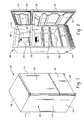
- FIGURES 1-4 illustrate various types of refrigerators with which the present disclosure can be used.
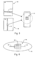
- FIGURE 5 is an enlarged representation of the encircled areas.
- FIGURE 6 is a still further enlarged representation of one preferred form of sensor used in FIGURE 5 .
- FIGURES 1-4 illustrate various models of refrigerators 100, and although the various models may have different features, for purposes of the present disclosure, many of these detailed features are not pertinent.
- these various types of refrigerators are all common with respect to including at least one cooled storage compartment, and preferably first and second cooled storage compartments generally referred to as a fresh food storage compartment and a freezer compartment. Therefore, like reference numerals will be used to identify like components throughout these FIGURES for ease of identification.
- the refrigerator 100 has a cabinet 102 that includes an outer case, shell, or housing 104 having a top wall 106, bottom wall 108, sidewalls 110, 112, and a rear or back wall 114.
- the housing is formed of a thin metal material and the walls are thermally insulated.
- a dividing wall 120 separates the refrigerator into a fresh food storage compartment 122 and a freezer compartment 124.
- FIGURES 1 and 2 can be in a bottom mount arrangement where the freezer is on the bottom and the fresh food is on the top, or a top mount where the freezer is on top and the fresh food compartment is on the bottom ( FIGURES 1 and 2 ), or a side-by-side model as shown in FIGURE 3 , or more recent vintage model of a fresh food compartment on top as shown in FIGURE 4 .
- the embodiments of FIGURES 1-3 each include a fresh food storage compartment door 132 and a freezer compartment door 134
- the particular model of FIGURE 4 includes a pair of fresh food storage compartment doors 136, 138 that are hinged adjacent the sidewalls 110, 112 and the freezer compartment is not a hinged door but a slidable drawer 140.
- the fresh food storage compartment and the freezer compartment are separated by the dividing wall and closed off from the ambient environment via the drawer or doors.
- a sealing member or gasket is provided about a perimeter of the door or drawer and engages a planar surface, typically a metal surface 150 of the housing 104 engaged by the gaskets 152, 154 that are mounted on the respective doors or drawer.
- the housing surfaces 150 selectively engaged by the gaskets are exposed to the cooler temperatures of the fresh food storage compartment and the freezer compartment along one edge or region and to ambient air along an adjacent edge or region.
- the thermally conductive metal surface tends to fall below the dew point of the surrounding atmosphere.
- FIGURES 1-4 are areas where condensation may accumulate and could lead to water dripping on the floor below the refrigerator.
- anti-sweat heaters are employed, and can be of the type described in the Background which heaters are well known in the art. These heaters are typically received in the mullion regions, i.e., incorporated along the edges of the door, case flange, mullions, etc. that are most common and where the gasket typically bears against the housing.
- mullion regions i.e., incorporated along the edges of the door, case flange, mullions, etc. that are most common and where the gasket typically bears against the housing.
- 4,332,142 and 4,822,117 show and describe such anti-sweat or mullion heaters that are employed in prior refrigerators to address the moisture issue.
- the mullion bars typically have insulation generally uniformly provided along an interior surface, i.e., behind them, in order to limit the thermal conduction from the cooler fresh food and freezer compartments.
- a preselected location 170 on the housing is created.
- the preselected location 170 is a depressed section, i.e., a region where the fog or sweat may coalesce, and behind the mullion is preferably a region with less insulation relative to adjacent regions of the insulated mullion.
- this preselected location or created area will tend to be cooler than adjacent regions of the mullion bar because of the reduced insulation.
- the depression acts as a collector for the fog or moisture that may develop in this location so that any moisture that does develop can be reliably considered as the incipient formation of moisture or a bead of water.
- the preselected location 170 includes a sensor 180.
- a preferred form of sensor 180 is an impedance grid sensor formed by first and second contacts 182, 184 that have interleaved portions 186 disposed in spaced locations and that is attached to the depressed, preselected location 170.
- the impedance between the sensor contacts 182, 184 in the interleaved portions 186 is monitored.
- the impedance will be very high as a result of the physical spacing between the contacts. However, as fog develops, the impedance is reduced permitting current to begin to flow between the contacts.
- the sensor impedance level that is communicated to a controller 190 of the refrigerator activates the anti-sweat heaters which were previously disabled during a peak pricing period.
- the anti-seat heaters are activated as a result of the reduced impedance level detection.
- the controller 190 automatically overrides the energy savings response (i.e., inactivating the anti-sweat heaters in this scenario) in order to activate the heaters and prevent moisture from dripping on the floor.
- the preselected location 170 can be any external surface of the appliance, and particularly one that is typically protected with an anti-sweat heater. Creating the imperfection (reduced insulation) provides greater control over an accurate location of the impedance sensor at the location of the imperfection. Depressing the region will also facilitate collection of the moisture at this location and allows the impedance sensor to be accurately monitored to provide for immediate override of the previously disable anti-sweat heaters through the demand response. In this manner, the anti-sweat heaters are activated.
- the impedance in a non-conductive state the impedance may be as high as 500K to 1M ohms.
- the fog or moisture may reduce the impedance to a level on the order of 1K to 20K ohms in a conductive state that represents incipient fog or moisture.
- the senor can continue to monitor the impedance and can shut off the heaters when the moisture is evaporated away or after a predetermined time, to provide for reduced energy use and associated cost savings.
- limits can be set to allow the anti-sweat heaters to duty cycle on and off between two impedance levels, such as between 1M ohm and 20K ohm.
- the anti-sweat heater can be turned on when the impedance is significantly reduced by the collection of moisture and the anti-sweat heater left on for a predetermined time period or for the remainder of the energy savings mode in order to prevent short-cycling of the anti-sweat heater (i.e., short cycling is frequent on/off cycling that can occur when the moisture is driven off and then accumulates again in a short timeframe so to avoid short cycling, then the anti-sweat heater can be left on for an extended period of time beyond the minimum impedance setpoint to further raise the temperature of the mullion region and keep sweat from developing too quickly).
- short cycling is frequent on/off cycling that can occur when the moisture is driven off and then accumulates again in a short timeframe so to avoid short cycling
- sensing the moisture or sweat early in the process can be helpful in preventing formation of beads of water.
- positioning the sensor in an area where the anti-sweat heater is located and where those skilled in the art expect sweat to form in the absence of the heater being on would be advantageous.
- mullion heaters are generally well known and such an anti-sweat heater is deemed to be one of the most cost effective manners of preventing the collection of condensation on the housing.
- one demand supply response to a peak pricing period can now be to turn off the mullion heaters since the inactivated anti-sweat heaters can be turned on once the sweat or moisture is detected.
- the energy savings period is still active, another response is to reduce the voltage or alter the operation of the anti-sweat heaters, e.g., the voltage can be pulsed or proportionally controlled, etc.
Landscapes
- Engineering & Computer Science (AREA)
- Chemical & Material Sciences (AREA)
- Combustion & Propulsion (AREA)
- Physics & Mathematics (AREA)
- Mechanical Engineering (AREA)
- Thermal Sciences (AREA)
- General Engineering & Computer Science (AREA)
- Devices That Are Associated With Refrigeration Equipment (AREA)
- Investigating Or Analyzing Materials By The Use Of Fluid Adsorption Or Reactions (AREA)
- Investigating Or Analyzing Materials By The Use Of Electric Means (AREA)
- Cold Air Circulating Systems And Constructional Details In Refrigerators (AREA)
Abstract
Description
- This disclosure relates to a demand supply response associated with an appliance, and particularly a refrigerator, freezer, wine chiller, etc. where operation of the appliance may be altered in response to a high demand for energy and peak pricing. Selected aspects may find application in related applications.
- It is well known that refrigerators have two or more compartments for storing food items, that is, at least one freezer compartment and at least one fresh food compartment. The locations of the separate compartments may vary, for example, from a bottom mount refrigerator where the freezer is located on the bottom and the fresh food compartment is on top or vice versa, to a side-by-side arrangement where one side is the freezer compartment and the other side is the fresh food compartment. These compartments are divided one from the other by one or more walls that are thermally insulated in order to maintain the temperature in the freezer compartment at, for example, about 0°F and in the fresh food compartment at approximately 37°F. Of course, these are exemplary temperature ranges only.
- Gaskets are provided to seal around access openings to these compartments and the gaskets extend from peripheral regions of doors that closes the access opening to the respective compartment. The gaskets sealingly contact a generally planar, perimeter surface of the housing or case that surrounds the access opening when the doors are closed. Thus, the metal or housing surface is exposed to 0° air from the freezer compartment, for example, along one edge of the gasket and exposed to ambient air associated with the room along another edge of the gasket. Since the metal housing is thermally conductive, a portion of this metal (sometimes referred to as a mullion bar), or specifically that housing area between a pair of gaskets, conducts the heat in and conducts the cold out. As a result, a gap region of the housing between the gaskets or adjacent the gaskets is exposed to ambient air and can be at a temperature below the dew point temperature. Fog or moisture can form beads of sweat in this mullion region and the beads can coalesce to form water droplets that potentially reach the floor.
- To prevent the formation of moisture or sweat in these regions, a heater such as a low wattage electric resistance heater is typically employed. This heater(s) is sometimes referred to as an anti-sweat or mullion heater. One type of these heaters operates on approximately 8 to 12 watts and is preferably a fine nichrome wire heater wrapped in and insulated by a surrounding vinyl sheathing. The wire is disposed on a cloth carrier that is attached to an adhesive backed foil. These small resistance-type heaters are usually secured to those areas of the refrigerator where sweat is likely to collect, for example along edges of the door, case flange, mullion, etc. In a side-by-side refrigerator, the gaskets of the side-by-side doors form a generally vertically extending channel there between which can contribute to potential water drippage through the channel. Understandably, water dripping on the floor adjacent the refrigerator is undesirable and thus the anti-sweat heaters are used to raise the temperature in these regions above the dew point.
- In response to utility companies beginning to charge higher rates during peak demand periods, there is a desire to control or reduce energy use by appliances which also results in a potential cost savings for the consumer/homeowner. Various responses have been proposed for different appliances, including refrigerators, when higher rates are being charged during peak demand periods. Generally speaking, inactivating or disabling anti-sweat heaters is sometimes avoided as a viable demand response option during peak pricing because of the potential concern that moisture or water could reach the floor. It is recognized that peak pricing periods could last two to four hours or more and, in this time frame, there is the possibility that sweat could develop in such regions. Moreover, 8-12 watts is deemed to be a relatively small value and thus proposed demand responses have focused on other energy and cost saving areas that could result in a greater energy savings.
- Consequently, a need exists for providing a demand response that addresses the anti-sweat heaters and the potential energy and cost savings associated therewith.
- An appliance, for example a refrigerator, includes a housing having a cooled storage compartment and an anti-sweat heater for warming at least a portion of the housing exposed to the ambient air. A controller is operatively connected to one or more power consuming features or functions of the refrigerator. The controller is configured to operate the appliance in a normal operating mode and/or an energy savings mode, specifically inactivating the anti-sweat heater in the energy savings mode, but activating the anti-sweat heater for at least a limited time period during the energy savings mode to limit sweat and moisture.
- The anti-sweat heater is cyclically activated by the controller during the energy savings mode.
- The refrigerator may include a moisture detecting sensor operative to detect the presence or absence of moisture proximate the sensor and the controller activates the anti-sweat heater in response to the sensor detecting moisture.
- The anti-sweat heater and sensor are incorporated into a mullion in the housing in one preferred arrangement, or located in a region where moisture tends to form.
- The controller automatically overrides the inactive status of the anti-sweat heater in the energy savings mode when sweat or fog is present and the anti-sweat heater is activated in response to sensing sweat or fog.
- The preferred form of the sensor is an impedance sensing device that changes electrical impedance in response to the presence of moisture or fog.
- The anti-sweat heater can be turned off once moisture or fog is removed, or alternatively operated for a pre-specified time after the absence of moisture is detected to prevent short cycling of the anti-sweat heater by the controller.
- A control method for the appliance or refrigerator receives a demand response signal that is indicative of at least a peak demand period and an off-peak demand period. During the off-peak demand period, the method includes operating the refrigerator in a normal mode. During the peak demand period, the method includes operating the refrigerator in an energy saving mode. The energy saving mode includes disabling an anti-sweat heater, providing a sensor on an external surface of the refrigerator, and enabling the anti-sweat heater during the peak demand period if moisture is detected by the sensor.
- The enabling step includes automatically overriding the demand response signal (inactivating the anti-sweat heater) and activating the anti-sweat heater in response to moisture.
- The enabling step includes creating a location on the housing where moisture will initially form and locating a sensor on the housing at the created location, one embodiment of which includes forming a depression on the refrigerator and locating the sensor at the depression where the moisture collects.
- The enabling step includes providing reduced thermal insulation in the housing at the created location to encourage moisture formation at the created location prior to forming on adjacent surfaces.
- In a preferred arrangement, the enabling step includes detecting the electrical impedance of a sensor located on the housing.
- A primary advantage is the ability to provide a low cost solution to taking advantage of load shedding in a peak demand period.
- Yet another advantage resides in a low cost solution that can be attained without the concern of sweat or moisture.
- Still another advantage is the lack of any moving parts or components that would otherwise lead to failure.
- Still another advantage is the ease with which the refrigerator can automatically and easily override a demand response signal to inactivate the anti-sweat heaters, and reactivate the anti-sweat heaters when fog or running beads of sweat are detected.
- Still other benefits and advantages of the present disclosure will become apparent from reading and understanding the following detailed description,
-
FIGURES 1-4 illustrate various types of refrigerators with which the present disclosure can be used. -
FIGURE 5 is an enlarged representation of the encircled areas. -
FIGURE 6 is a still further enlarged representation of one preferred form of sensor used inFIGURE 5 . -
FIGURES 1-4 illustrate various models ofrefrigerators 100, and although the various models may have different features, for purposes of the present disclosure, many of these detailed features are not pertinent. Thus, these various types of refrigerators are all common with respect to including at least one cooled storage compartment, and preferably first and second cooled storage compartments generally referred to as a fresh food storage compartment and a freezer compartment. Therefore, like reference numerals will be used to identify like components throughout these FIGURES for ease of identification. - More particularly, the
refrigerator 100 has acabinet 102 that includes an outer case, shell, orhousing 104 having atop wall 106,bottom wall 108,sidewalls wall 120 separates the refrigerator into a freshfood storage compartment 122 and afreezer compartment 124. These compartments can be in a bottom mount arrangement where the freezer is on the bottom and the fresh food is on the top, or a top mount where the freezer is on top and the fresh food compartment is on the bottom (FIGURES 1 and 2 ), or a side-by-side model as shown inFIGURE 3 , or more recent vintage model of a fresh food compartment on top as shown inFIGURE 4 . Whereas the embodiments ofFIGURES 1-3 each include a fresh foodstorage compartment door 132 and afreezer compartment door 134, the particular model ofFIGURE 4 includes a pair of fresh foodstorage compartment doors sidewalls slidable drawer 140. As is well understood in the art, the fresh food storage compartment and the freezer compartment are separated by the dividing wall and closed off from the ambient environment via the drawer or doors. - A sealing member or gasket is provided about a perimeter of the door or drawer and engages a planar surface, typically a
metal surface 150 of thehousing 104 engaged by thegaskets housing surfaces 150 selectively engaged by the gaskets are exposed to the cooler temperatures of the fresh food storage compartment and the freezer compartment along one edge or region and to ambient air along an adjacent edge or region. When the cooled, refrigerated air impinges on any exposed metal within the refrigerated space, conducts through the cross-section of the gasket, or leaks past the gasket or seal area, the thermally conductive metal surface tends to fall below the dew point of the surrounding atmosphere. These regions, therefore, are prone to potential accumulation of fog, moisture, or water droplets. Therefore, the representative encircled regions inFIGURES 1-4 are areas where condensation may accumulate and could lead to water dripping on the floor below the refrigerator. To overcome this problem, anti-sweat heaters are employed, and can be of the type described in the Background which heaters are well known in the art. These heaters are typically received in the mullion regions, i.e., incorporated along the edges of the door, case flange, mullions, etc. that are most common and where the gasket typically bears against the housing. For example, commonly-ownedU.S. Patent Nos. 4,332,142 and4,822,117 show and describe such anti-sweat or mullion heaters that are employed in prior refrigerators to address the moisture issue. The mullion bars typically have insulation generally uniformly provided along an interior surface, i.e., behind them, in order to limit the thermal conduction from the cooler fresh food and freezer compartments. - As shown in
FIGURE 5 , apreselected location 170 on the housing is created. In a preferred arrangement, thepreselected location 170 is a depressed section, i.e., a region where the fog or sweat may coalesce, and behind the mullion is preferably a region with less insulation relative to adjacent regions of the insulated mullion. As a result, this preselected location or created area will tend to be cooler than adjacent regions of the mullion bar because of the reduced insulation. Moreover, the depression acts as a collector for the fog or moisture that may develop in this location so that any moisture that does develop can be reliably considered as the incipient formation of moisture or a bead of water. - With continued reference to
FIGURE 5 and additional reference toFIGURE 6 , thepreselected location 170 includes asensor 180. A preferred form ofsensor 180 is an impedance grid sensor formed by first andsecond contacts portions 186 disposed in spaced locations and that is attached to the depressed,preselected location 170. The impedance between thesensor contacts portions 186 is monitored. Typically the impedance will be very high as a result of the physical spacing between the contacts. However, as fog develops, the impedance is reduced permitting current to begin to flow between the contacts. At a selected threshold impedance level (that correlates to a level of acceptable/ unacceptable moisture), the sensor impedance level that is communicated to acontroller 190 of the refrigerator activates the anti-sweat heaters which were previously disabled during a peak pricing period. The anti-seat heaters are activated as a result of the reduced impedance level detection. Even if the demand signal or utility indicates that reduced energy use is desired, the sensor provides a signal of incipient moisture formation and thecontroller 190 automatically overrides the energy savings response (i.e., inactivating the anti-sweat heaters in this scenario) in order to activate the heaters and prevent moisture from dripping on the floor. - It will be appreciated that the
preselected location 170 can be any external surface of the appliance, and particularly one that is typically protected with an anti-sweat heater. Creating the imperfection (reduced insulation) provides greater control over an accurate location of the impedance sensor at the location of the imperfection. Depressing the region will also facilitate collection of the moisture at this location and allows the impedance sensor to be accurately monitored to provide for immediate override of the previously disable anti-sweat heaters through the demand response. In this manner, the anti-sweat heaters are activated. - Although the following values are representative only, in a non-conductive state the impedance may be as high as 500K to 1M ohms. On the other hand, the fog or moisture may reduce the impedance to a level on the order of 1K to 20K ohms in a conductive state that represents incipient fog or moisture.
- Once the anti-sweat heaters are turned on in the energy savings mode as a result of detecting moisture or fog, the sensor can continue to monitor the impedance and can shut off the heaters when the moisture is evaporated away or after a predetermined time, to provide for reduced energy use and associated cost savings. Thus, limits can be set to allow the anti-sweat heaters to duty cycle on and off between two impedance levels, such as between 1M ohm and 20K ohm. Alternatively, the anti-sweat heater can be turned on when the impedance is significantly reduced by the collection of moisture and the anti-sweat heater left on for a predetermined time period or for the remainder of the energy savings mode in order to prevent short-cycling of the anti-sweat heater (i.e., short cycling is frequent on/off cycling that can occur when the moisture is driven off and then accumulates again in a short timeframe so to avoid short cycling, then the anti-sweat heater can be left on for an extended period of time beyond the minimum impedance setpoint to further raise the temperature of the mullion region and keep sweat from developing too quickly).
- It will be appreciated that sensing the moisture or sweat early in the process can be helpful in preventing formation of beads of water. Thus, positioning the sensor in an area where the anti-sweat heater is located and where those skilled in the art expect sweat to form in the absence of the heater being on would be advantageous.
- The structure and operation of mullion heaters are generally well known and such an anti-sweat heater is deemed to be one of the most cost effective manners of preventing the collection of condensation on the housing. As a result, one demand supply response to a peak pricing period can now be to turn off the mullion heaters since the inactivated anti-sweat heaters can be turned on once the sweat or moisture is detected. It is also contemplated that if the energy savings period is still active, another response is to reduce the voltage or alter the operation of the anti-sweat heaters, e.g., the voltage can be pulsed or proportionally controlled, etc.
- The disclosure has been described with reference to the preferred embodiments. Obviously, modifications and alterations will occur to others upon reading and understanding the preceding detailed description. It is intended that the invention be construed as including all such modifications and alterations.
- Various aspects and embodiments of the present invention are defined by the following numbered clauses:
- 1. A refrigerator comprising:
- a housing enclosing a cooled storage compartment;
- an anti- sweat heater for warming at least a portion of the housing; and
- a controller operatively connected to one or more power consuming features/functions of the refrigerator, the controller being configured to receive and process a demand response signal and in response thereto operate the appliance in one of a plurality of operating modes including at least a normal operating mode and an energy savings mode, the controller being configured in at least the energy savings mode to inactivate the anti-sweat heater and at least selectively activate the anti-sweat heater for at least a limited time period during the energy savings mode.
- 2. The refrigerator of clause 1, wherein the controller cyclically activates the anti-sweat heater during the energy savings mode.
- 3. The refrigerator of clause 1 or clause 2, further comprising a moisture detecting sensor operative to detect the presence and absence of moisture proximate the sensor and in operative communication with the controller and wherein the controller activates the anti-sweat heater in response to the sensor detecting moisture or fog.
- 4. The refrigerator of any preceding clause, wherein the anti-sweat heater and sensor are incorporated into a mullion of the housing.
- 5. The refrigerator of any preceding clause, wherein the sensor is located in a region where moisture tends to form.
- 6. The refrigerator of any preceding clause, wherein the controller activates the anti-sweat heater to duty cycle to maintain a first temperature during the energy savings mode that is lower than a second temperature which is maintained for the anti-sweat heater in the normal operation mode.
- 7. The refrigerator of any preceding clause, wherein the controller automatically overrides the inactive status of the anti-sweat heater in the energy savings mode and activates the anti-sweat heater when sweat or fog is present.
- 8. The refrigerator of any preceding clause, further comprising a moisture detecting sensor in operative communication with the controller whereby the controller activates the anti-sweat heater in response to moisture detected by the sensor, the sensor including an impedance sensing device that changes electrical impedance in response to the presence of moisture or fog.
- 9. The refrigerator of any preceding clause, wherein the impedance sensing device signals the controller once the moisture or fog is removed by the anti-sweat heater so that the anti-sweat heater can be turned off.
- 10. The refrigerator of any preceding clause, wherein the controller is operative to continue energization of the anti-sweat heater for a pre-specified time after the absence of moisture is detected by the sensor to prevent short-cycling of the anti-sweat heater by the controller.
- 11. A control method for an appliance, comprising:
- receiving a demand response signal indicative of at least a peak demand period and an off-peak demand period;
- operating the appliance in a normal mode during the off-peak demand period;
- operating the appliance in an energy savings mode during the peak demand period;
- disabling an anti-sweat heater operatively associated with a housing of the appliance during the peak demand period;
- providing a sensor on an external surface of the appliance; and enabling the anti-sweat heater during the peak demand period if moisture is detected by the sensor.
- 12. The method of clause 11, wherein the enabling step includes automatically overriding the demand response signal and activating the anti-sweat heater in response to moisture or fog formation at the sensor.
- 13. The method of clause 11 or clause 12, further comprising forming a depression on the appliance and wherein the enabling step includes locating the sensor at the depression where moisture collects.
- 14. The method of any of clauses 11 to 13, wherein the enabling step includes creating a location on the housing where moisture will initially form and locating a sensor on the housing at the created location.
- 15. The method of any of clauses 11 to 14, wherein the enabling step includes providing reduced thermal insulation on the housing at the created location to encourage moisture to initially form at the created location prior to forming on adjacent surfaces.
- 16. The method of any of clauses 11 to 15, wherein the enabling step is operational for a preselected time period after the sensor indicates an absence of moisture or fog to prevent short-cycling of the anti-sweat heater.
- 17. The method of any of clauses 11 to 16, wherein the enabling step is responsive to a detected first electrical impedance of a sensor located on the housing.
- 18. The method of any of clauses 11 to 17, further comprising disabling the anti-sweat heater in response to a detected second electrical impedance of the sensor.
- 19. An appliance comprising:
- a housing enclosing a cooled storage compartment;
- an electrical anti- sweat heater incorporated into a region of the housing susceptible to moisture or fog in a high humidity environment;
- a controller operatively connected to one or more power consuming features/functions of the refrigerator, the controller being configured to receive and process a demand response signal and in response thereto operate the appliance in one of a plurality of operating modes including at least a normal operating mode and an energy savings mode, the controller being configured in at least the energy savings mode to inactivate the anti-sweat heater; and
- a moisture detecting sensor located at the housing region and in operative communication with the controller for activating the anti-sweat heater in response to the sensor detecting moisture or fog.
- 20. The appliance of clause 19 wherein the housing region has a reduced amount of thermal insulation compared to adjacent areas of the housing in order to encourage formation of moisture or fog at the region in a high humidity environment.
Claims (15)
- A refrigerator (100) comprising:a housing (104) enclosing a cooled storage compartment;an anti- sweat heater for warming at least a portion of the housing; anda controller operatively connected to one or more power consuming features/functions of the refrigerator, the controller being configured to receive and process a demand response signal and in response thereto operate the appliance in one of a plurality of operating modes including at least a normal operating mode and an energy savings mode, the controller being configured in at least the energy savings mode to inactivate the anti-sweat heater and at least selectively activate the anti-sweat heater for at least a limited time period during the energy savings mode.
- The refrigerator of claim 1, further comprising a moisture detecting sensor (180) operative to detect the presence and absence of moisture proximate the sensor and in operative communication with the controller and wherein the controller activates the anti-sweat heater in response to the sensor detecting moisture or fog.
- The refrigerator of claim 1 or claim 2, wherein the anti-sweat heater and sensor are incorporated into a mullion (150) of the housing.
- The refrigerator of any preceding claim, wherein the sensor is located in a region where moisture tends to form.
- The refrigerator of any preceding claim, wherein the controller activates the anti-sweat heater to duty cycle to maintain a first temperature during the energy savings mode that is lower than a second temperature which is maintained for the anti-sweat heater in the normal operation mode.
- The refrigerator of any preceding claim, further comprising a moisture detecting sensor in operative communication with the controller whereby the controller activates the anti-sweat heater in response to moisture detected by the sensor, the sensor including an impedance sensing device that changes electrical impedance in response to the presence of moisture or fog.
- The refrigerator of any preceding claim, wherein the controller is operative to continue energization of the anti-sweat heater for a pre-specified time after the absence of moisture is detected by the sensor to prevent short-cycling of the anti-sweat heater by the controller.
- A control method for an appliance, comprising:receiving a demand response signal indicative of at least a peak demand period and an off-peak demand period;operating the appliance in a normal mode during the off-peak demand period;operating the appliance in an energy savings mode during the peak demand period;disabling an anti-sweat heater operatively associated with a housing of the appliance during the peak demand period;providing a sensor on an external surface of the appliance; and enabling the anti-sweat heater during the peak demand period if moisture is detected by the sensor.
- The method of claim 8, wherein the enabling step includes automatically overriding the demand response signal and activating the anti-sweat heater in response to moisture or fog formation at the sensor.
- The method of claim 8 or claim 9, wherein the enabling step includes creating a location on the housing where moisture will initially form and locating a sensor on the housing at the created location.
- The method of any of claims 8 to 10, wherein the enabling step includes providing reduced thermal insulation on the housing at the created location to encourage moisture to initially form at the created location prior to forming on adjacent surfaces.
- The method of any of claims 8 to 11, wherein the enabling step is operational for a preselected time period after the sensor indicates an absence of moisture or fog to prevent short-cycling of the anti-sweat heater.
- The method of any of claims 8 to 12, wherein the enabling step is responsive to a detected first electrical impedance of a sensor located on the housing.
- The method of any of claims 8 to 13, further comprising disabling the anti-sweat heater in response to a detected second electrical impedance of the sensor.
- An appliance comprising:a housing enclosing a cooled storage compartment;an electrical anti- sweat heater incorporated into a region of the housing susceptible to moisture or fog in a high humidity environment;a controller operatively connected to one or more power consuming features/functions of the refrigerator, the controller being configured to receive and process a demand response signal and in response thereto operate the appliance in one of a plurality of operating modes including at least a normal operating mode and an energy savings mode, the controller being configured in at least the energy savings mode to inactivate the anti-sweat heater; anda moisture detecting sensor located at the housing region and in operative communication with the controller for activating the anti-sweat heater in response to the sensor detecting moisture or fog.
Applications Claiming Priority (1)
| Application Number | Priority Date | Filing Date | Title |
|---|---|---|---|
| US12/859,411 US9291383B2 (en) | 2010-08-19 | 2010-08-19 | Demand response mullion sweat protection |
Publications (3)
| Publication Number | Publication Date |
|---|---|
| EP2426444A2 true EP2426444A2 (en) | 2012-03-07 |
| EP2426444A3 EP2426444A3 (en) | 2017-11-15 |
| EP2426444B1 EP2426444B1 (en) | 2019-04-17 |
Family
ID=45498171
Family Applications (1)
| Application Number | Title | Priority Date | Filing Date |
|---|---|---|---|
| EP11177844.5A Active EP2426444B1 (en) | 2010-08-19 | 2011-08-17 | Demand response mullion sweat protection |
Country Status (5)
| Country | Link |
|---|---|
| US (1) | US9291383B2 (en) |
| EP (1) | EP2426444B1 (en) |
| CN (1) | CN102519214B (en) |
| AU (1) | AU2011211373B2 (en) |
| CA (1) | CA2748150C (en) |
Cited By (2)
| Publication number | Priority date | Publication date | Assignee | Title |
|---|---|---|---|---|
| EP3267186A4 (en) * | 2015-03-05 | 2018-02-21 | LG Innotek Co., Ltd. | Sensing module and refrigerator including same |
| US9980581B2 (en) | 2012-09-24 | 2018-05-29 | Carrier Corporation | Refrigerated sales cabinet |
Families Citing this family (11)
| Publication number | Priority date | Publication date | Assignee | Title |
|---|---|---|---|---|
| CN105222476A (en) * | 2015-10-13 | 2016-01-06 | 合肥晶弘三菱电机家电技术开发有限公司 | A kind of anti-condensation heating system of turnover beam of refrigerator and control method thereof |
| KR101852434B1 (en) | 2016-02-02 | 2018-04-26 | 엘지전자 주식회사 | Apparatus for sensing and removing dew of refrigerator and method controlling thereof |
| EP4617594A3 (en) | 2018-03-02 | 2025-11-12 | Electrolux Do Brasil S.A. | Refrigerator with a door warmer |
| CN113226177B (en) | 2018-11-13 | 2025-02-25 | 尼克斯股份有限公司 | Wearable systems, devices and methods for measuring and analyzing body fluids |
| CN109556348B (en) * | 2018-11-29 | 2020-12-04 | 台州新凯科技服务有限公司 | Steam Site Identification System |
| US11123011B1 (en) | 2020-03-23 | 2021-09-21 | Nix, Inc. | Wearable systems, devices, and methods for measurement and analysis of body fluids |
| CN112212597A (en) * | 2020-10-23 | 2021-01-12 | 海信容声(广东)冰箱有限公司 | A refrigerator and its control method |
| US12584678B2 (en) | 2021-03-29 | 2026-03-24 | Midea Group Co., Ltd. | Refrigerator with dynamic multi-zone anti-sweat heating system |
| CN113803940A (en) * | 2021-10-14 | 2021-12-17 | 珠海格力电器股份有限公司 | Anti-condensation device and refrigeration storage equipment |
| US20250271203A1 (en) * | 2024-02-22 | 2025-08-28 | Haier Us Appliance Solutions, Inc. | Refrigerator appliance with condensation mitigation features |
| CN119802951B (en) * | 2025-01-14 | 2026-01-23 | Tcl家用电器(合肥)有限公司 | Anti-condensation control method and device, refrigerator and storage medium |
Citations (2)
| Publication number | Priority date | Publication date | Assignee | Title |
|---|---|---|---|---|
| US4332142A (en) | 1980-10-14 | 1982-06-01 | General Electric Company | Household refrigerator including anti-sweat heater control circuit |
| US4822117A (en) | 1987-06-12 | 1989-04-18 | General Electric Company | Refrigerator case/liner interface and related components for automated assembly |
Family Cites Families (40)
| Publication number | Priority date | Publication date | Assignee | Title |
|---|---|---|---|---|
| US3859502A (en) * | 1974-02-11 | 1975-01-07 | Anthony S Mfg Co | Defrosting system for refrigerator doors |
| US3939666A (en) * | 1974-09-30 | 1976-02-24 | Whirlpool Corporation | Stile and mullion heater control |
| US4142092A (en) * | 1978-01-05 | 1979-02-27 | General Electric Company | Refrigerator cabinet case heater installation |
| US4127765A (en) * | 1978-02-17 | 1978-11-28 | Anthony's Manufacturing Company, Inc. | Anti-condensation system for refrigerator doors |
| US4260876A (en) * | 1978-12-11 | 1981-04-07 | Anthony's Manufacturing Company, Inc. | Dew point differential power controller |
| US4474017A (en) * | 1982-09-07 | 1984-10-02 | General Electric Company | Method of assembling an anti-sweat heater in a refrigerator cabinet |
| US4862701A (en) * | 1986-09-25 | 1989-09-05 | Nv Raychem Sa | Moisture detection |
| US4941289A (en) * | 1987-12-10 | 1990-07-17 | Ardco, Inc. | Refrigerator door frame with insulated mullion |
| US4881315A (en) * | 1989-01-18 | 1989-11-21 | General Electric Company | Method of assembling an anti-sweat heater in a refrigerator cabinet |
| US5255531A (en) * | 1993-01-05 | 1993-10-26 | Whirlpool Corporation | Refrigerator mullion assembly with hot gas defrost tube |
| US5277035A (en) * | 1993-03-31 | 1994-01-11 | Aluminum Company Of America | Multi-compartment refrigerator with system for minimizing condensation |
| CA2123029C (en) | 1994-05-06 | 2002-09-10 | Nedo Banicevic | Refrigerator anti sweat device |
| US5598349A (en) * | 1994-10-25 | 1997-01-28 | Honeywell Inc. | Responding to pricing signals from a power supplier using mixed add/shed and profile setback delta schemes |
| US5899078A (en) * | 1997-03-25 | 1999-05-04 | Peak Energy Systems, Inc. | Method and apparatus for reducing energy use by refrigeration door and frame heaters |
| US5778689A (en) * | 1997-05-19 | 1998-07-14 | Beatenbough; Bryan | System for maintaining refrigeration doors free of frost and condensation |
| CA2284234C (en) * | 1998-10-01 | 2003-09-16 | Samsung Electronics Co., Ltd. | Method and apparatus for predicting power consumption of refrigerator having defrosting heater |
| US6324853B1 (en) * | 2000-09-28 | 2001-12-04 | Spx Corporation | De-icing for low temperature refrigeration devices |
| US6631622B1 (en) * | 2002-03-22 | 2003-10-14 | Whirlpool Corporation | Demand side management of freezer systems |
| US6739146B1 (en) * | 2003-03-12 | 2004-05-25 | Maytag Corporation | Adaptive defrost control for a refrigerator |
| US7010363B2 (en) * | 2003-06-13 | 2006-03-07 | Battelle Memorial Institute | Electrical appliance energy consumption control methods and electrical energy consumption systems |
| US7137262B2 (en) * | 2003-12-05 | 2006-11-21 | Kendro Laboratory Products, Lp | Supplemental heat control apparatus and method for freezer/refrigeration equipment |
| US7240501B2 (en) * | 2004-02-11 | 2007-07-10 | Door Miser, Llc | System for preventing condensation on refrigerator doors and frames |
| US20060026975A1 (en) | 2004-02-11 | 2006-02-09 | John Bunch | Wireless system for preventing condensation on refrigerator doors and frames |
| KR20050096337A (en) * | 2004-03-30 | 2005-10-06 | 삼성전자주식회사 | A refrigerator and defrosting method thereof |
| US20050229614A1 (en) * | 2004-04-02 | 2005-10-20 | Altech Controls, Inc. | Anti-sweat heater control system and method |
| US7793509B2 (en) * | 2004-04-12 | 2010-09-14 | Johnson Controls Technology Company | System and method for capacity control in a multiple compressor chiller system |
| US7340907B2 (en) * | 2004-05-10 | 2008-03-11 | Computer Process Controls, Inc. | Anti-condensation control system |
| US7207181B2 (en) * | 2005-03-01 | 2007-04-24 | Bradley W. Geuke | Refrigeration unit condensation prevention |
| US20080115514A1 (en) * | 2006-11-20 | 2008-05-22 | Steimel John C | Condensation prevention apparatus and method |
| US7845576B2 (en) * | 2007-06-28 | 2010-12-07 | Honeywell International Inc. | Thermostat with fixed segment display having both fixed segment icons and a variable text display capacity |
| US20090090114A1 (en) * | 2007-10-09 | 2009-04-09 | Nico Technology Ltd. | Refrigeration control device to reduce power consumption of a refrigeration appliance |
| EP3121060A1 (en) * | 2008-02-01 | 2017-01-25 | Gentherm Incorporated | Condensation and humidity sensors for thermoelectric devices |
| CA2723051C (en) * | 2008-09-15 | 2016-12-06 | General Electric Company | Energy management of dishwasher appliance |
| CN101684980B (en) | 2008-09-27 | 2012-07-25 | 海尔集团公司 | Working mode for controlling heating of anti-condensation by using humidity sensor on refrigerator |
| US8250873B2 (en) * | 2008-10-03 | 2012-08-28 | Anthony, Inc. | Anti-condensation control system |
| CN201377956Y (en) | 2009-04-24 | 2010-01-06 | 星星集团有限公司 | Anti-dewing device of intermediate parting strips of refrigerator |
| CN201478706U (en) | 2009-06-23 | 2010-05-19 | 卢景华 | Switch cabinet anti-condensation controller |
| US20110094292A1 (en) * | 2009-10-23 | 2011-04-28 | Mingsheng Liu | Apparatus for air property measurement |
| KR101595391B1 (en) * | 2009-10-26 | 2016-02-18 | 엘지전자 주식회사 | Washing machine control device and control method |
| US8434317B2 (en) * | 2010-08-19 | 2013-05-07 | General Electric Company | Anti-sweat heater demand supply module using temperature and humidity control |
-
2010
- 2010-08-19 US US12/859,411 patent/US9291383B2/en active Active
-
2011
- 2011-08-04 CA CA2748150A patent/CA2748150C/en active Active
- 2011-08-11 AU AU2011211373A patent/AU2011211373B2/en active Active
- 2011-08-17 EP EP11177844.5A patent/EP2426444B1/en active Active
- 2011-08-19 CN CN201110280116.1A patent/CN102519214B/en active Active
Patent Citations (2)
| Publication number | Priority date | Publication date | Assignee | Title |
|---|---|---|---|---|
| US4332142A (en) | 1980-10-14 | 1982-06-01 | General Electric Company | Household refrigerator including anti-sweat heater control circuit |
| US4822117A (en) | 1987-06-12 | 1989-04-18 | General Electric Company | Refrigerator case/liner interface and related components for automated assembly |
Cited By (4)
| Publication number | Priority date | Publication date | Assignee | Title |
|---|---|---|---|---|
| US9980581B2 (en) | 2012-09-24 | 2018-05-29 | Carrier Corporation | Refrigerated sales cabinet |
| US10285512B2 (en) | 2012-09-24 | 2019-05-14 | Carrier Corporation | Refrigerated sales cabinet |
| EP3267186A4 (en) * | 2015-03-05 | 2018-02-21 | LG Innotek Co., Ltd. | Sensing module and refrigerator including same |
| US10808985B2 (en) | 2015-03-05 | 2020-10-20 | Lg Innotek Co., Ltd. | Sensing module and refrigerator including same |
Also Published As
| Publication number | Publication date |
|---|---|
| AU2011211373A1 (en) | 2012-03-08 |
| US9291383B2 (en) | 2016-03-22 |
| US20120042666A1 (en) | 2012-02-23 |
| CA2748150A1 (en) | 2012-02-19 |
| EP2426444B1 (en) | 2019-04-17 |
| CN102519214B (en) | 2015-08-19 |
| CN102519214A (en) | 2012-06-27 |
| EP2426444A3 (en) | 2017-11-15 |
| AU2011211373B2 (en) | 2016-05-19 |
| CA2748150C (en) | 2020-02-18 |
Similar Documents
| Publication | Publication Date | Title |
|---|---|---|
| EP2426444B1 (en) | Demand response mullion sweat protection | |
| US8434317B2 (en) | Anti-sweat heater demand supply module using temperature and humidity control | |
| EP2520880B1 (en) | Cooling box | |
| US20140216706A1 (en) | Humidity control sensor for a refrigerator | |
| KR101753755B1 (en) | Defrosting control apparatus and defrosting methods for indirectness cooling system | |
| JP7201412B2 (en) | cold storage | |
| JP2011208906A (en) | Refrigerator | |
| EP2420773A2 (en) | Refrigerator | |
| JP5722057B2 (en) | Cooling storage | |
| KR102658800B1 (en) | refrigerator for vehicle, and vehicle | |
| CN102735010A (en) | Refrigerating apparatus | |
| EP4127580B1 (en) | Refrigerator with dynamic multi-zone anti-sweat heating system | |
| CN204923679U (en) | Refrigerator | |
| US6789392B1 (en) | Power interrupt system for a refrigerated appliance | |
| CN112432420B (en) | Demisting control system and method thereof | |
| CN114198961A (en) | Intelligent anti-condensation refrigerator device | |
| CN118705801B (en) | Method, device, equipment and storage medium for preventing condensation | |
| US11768031B1 (en) | Refrigerator appliance and methods for responding to ambient humidity levels | |
| Besore | Demand response mullion sweat protection | |
| JP6657032B2 (en) | Cooling storage | |
| JP6657031B2 (en) | Cooling storage | |
| US20180135906A1 (en) | Refrigerator appliance and heating assembly | |
| DK178891B1 (en) | Control system for refrigerated equipment and apparatus with advanced energy saving features | |
| US20180329437A1 (en) | Systems and methods for refrigerator control | |
| EP4056932A1 (en) | Refrigeration appliance, and heating assembly having hydrophobic layer |
Legal Events
| Date | Code | Title | Description |
|---|---|---|---|
| AK | Designated contracting states |
Kind code of ref document: A2 Designated state(s): AL AT BE BG CH CY CZ DE DK EE ES FI FR GB GR HR HU IE IS IT LI LT LU LV MC MK MT NL NO PL PT RO RS SE SI SK SM TR |
|
| AX | Request for extension of the european patent |
Extension state: BA ME |
|
| PUAI | Public reference made under article 153(3) epc to a published international application that has entered the european phase |
Free format text: ORIGINAL CODE: 0009012 |
|
| RAP1 | Party data changed (applicant data changed or rights of an application transferred) |
Owner name: HAIER US APPLIANCE SOLUTIONS, INC. |
|
| PUAL | Search report despatched |
Free format text: ORIGINAL CODE: 0009013 |
|
| AK | Designated contracting states |
Kind code of ref document: A3 Designated state(s): AL AT BE BG CH CY CZ DE DK EE ES FI FR GB GR HR HU IE IS IT LI LT LU LV MC MK MT NL NO PL PT RO RS SE SI SK SM TR |
|
| AX | Request for extension of the european patent |
Extension state: BA ME |
|
| RIC1 | Information provided on ipc code assigned before grant |
Ipc: F25D 21/04 20060101AFI20171009BHEP Ipc: F25D 21/02 20060101ALI20171009BHEP |
|
| STAA | Information on the status of an ep patent application or granted ep patent |
Free format text: STATUS: REQUEST FOR EXAMINATION WAS MADE |
|
| 17P | Request for examination filed |
Effective date: 20180514 |
|
| RBV | Designated contracting states (corrected) |
Designated state(s): AL AT BE BG CH CY CZ DE DK EE ES FI FR GB GR HR HU IE IS IT LI LT LU LV MC MK MT NL NO PL PT RO RS SE SI SK SM TR |
|
| GRAP | Despatch of communication of intention to grant a patent |
Free format text: ORIGINAL CODE: EPIDOSNIGR1 |
|
| STAA | Information on the status of an ep patent application or granted ep patent |
Free format text: STATUS: GRANT OF PATENT IS INTENDED |
|
| INTG | Intention to grant announced |
Effective date: 20181107 |
|
| GRAS | Grant fee paid |
Free format text: ORIGINAL CODE: EPIDOSNIGR3 |
|
| GRAA | (expected) grant |
Free format text: ORIGINAL CODE: 0009210 |
|
| STAA | Information on the status of an ep patent application or granted ep patent |
Free format text: STATUS: THE PATENT HAS BEEN GRANTED |
|
| AK | Designated contracting states |
Kind code of ref document: B1 Designated state(s): AL AT BE BG CH CY CZ DE DK EE ES FI FR GB GR HR HU IE IS IT LI LT LU LV MC MK MT NL NO PL PT RO RS SE SI SK SM TR |
|
| REG | Reference to a national code |
Ref country code: GB Ref legal event code: FG4D |
|
| REG | Reference to a national code |
Ref country code: CH Ref legal event code: EP |
|
| REG | Reference to a national code |
Ref country code: DE Ref legal event code: R096 Ref document number: 602011058096 Country of ref document: DE |
|
| REG | Reference to a national code |
Ref country code: AT Ref legal event code: REF Ref document number: 1121997 Country of ref document: AT Kind code of ref document: T Effective date: 20190515 Ref country code: IE Ref legal event code: FG4D |
|
| REG | Reference to a national code |
Ref country code: NL Ref legal event code: MP Effective date: 20190417 |
|
| REG | Reference to a national code |
Ref country code: LT Ref legal event code: MG4D |
|
| PG25 | Lapsed in a contracting state [announced via postgrant information from national office to epo] |
Ref country code: NL Free format text: LAPSE BECAUSE OF FAILURE TO SUBMIT A TRANSLATION OF THE DESCRIPTION OR TO PAY THE FEE WITHIN THE PRESCRIBED TIME-LIMIT Effective date: 20190417 |
|
| PG25 | Lapsed in a contracting state [announced via postgrant information from national office to epo] |
Ref country code: ES Free format text: LAPSE BECAUSE OF FAILURE TO SUBMIT A TRANSLATION OF THE DESCRIPTION OR TO PAY THE FEE WITHIN THE PRESCRIBED TIME-LIMIT Effective date: 20190417 Ref country code: HR Free format text: LAPSE BECAUSE OF FAILURE TO SUBMIT A TRANSLATION OF THE DESCRIPTION OR TO PAY THE FEE WITHIN THE PRESCRIBED TIME-LIMIT Effective date: 20190417 Ref country code: LT Free format text: LAPSE BECAUSE OF FAILURE TO SUBMIT A TRANSLATION OF THE DESCRIPTION OR TO PAY THE FEE WITHIN THE PRESCRIBED TIME-LIMIT Effective date: 20190417 Ref country code: FI Free format text: LAPSE BECAUSE OF FAILURE TO SUBMIT A TRANSLATION OF THE DESCRIPTION OR TO PAY THE FEE WITHIN THE PRESCRIBED TIME-LIMIT Effective date: 20190417 Ref country code: NO Free format text: LAPSE BECAUSE OF FAILURE TO SUBMIT A TRANSLATION OF THE DESCRIPTION OR TO PAY THE FEE WITHIN THE PRESCRIBED TIME-LIMIT Effective date: 20190717 Ref country code: PT Free format text: LAPSE BECAUSE OF FAILURE TO SUBMIT A TRANSLATION OF THE DESCRIPTION OR TO PAY THE FEE WITHIN THE PRESCRIBED TIME-LIMIT Effective date: 20190817 Ref country code: AL Free format text: LAPSE BECAUSE OF FAILURE TO SUBMIT A TRANSLATION OF THE DESCRIPTION OR TO PAY THE FEE WITHIN THE PRESCRIBED TIME-LIMIT Effective date: 20190417 Ref country code: SE Free format text: LAPSE BECAUSE OF FAILURE TO SUBMIT A TRANSLATION OF THE DESCRIPTION OR TO PAY THE FEE WITHIN THE PRESCRIBED TIME-LIMIT Effective date: 20190417 |
|
| PG25 | Lapsed in a contracting state [announced via postgrant information from national office to epo] |
Ref country code: LV Free format text: LAPSE BECAUSE OF FAILURE TO SUBMIT A TRANSLATION OF THE DESCRIPTION OR TO PAY THE FEE WITHIN THE PRESCRIBED TIME-LIMIT Effective date: 20190417 Ref country code: PL Free format text: LAPSE BECAUSE OF FAILURE TO SUBMIT A TRANSLATION OF THE DESCRIPTION OR TO PAY THE FEE WITHIN THE PRESCRIBED TIME-LIMIT Effective date: 20190417 Ref country code: BG Free format text: LAPSE BECAUSE OF FAILURE TO SUBMIT A TRANSLATION OF THE DESCRIPTION OR TO PAY THE FEE WITHIN THE PRESCRIBED TIME-LIMIT Effective date: 20190717 Ref country code: GR Free format text: LAPSE BECAUSE OF FAILURE TO SUBMIT A TRANSLATION OF THE DESCRIPTION OR TO PAY THE FEE WITHIN THE PRESCRIBED TIME-LIMIT Effective date: 20190718 Ref country code: RS Free format text: LAPSE BECAUSE OF FAILURE TO SUBMIT A TRANSLATION OF THE DESCRIPTION OR TO PAY THE FEE WITHIN THE PRESCRIBED TIME-LIMIT Effective date: 20190417 |
|
| REG | Reference to a national code |
Ref country code: AT Ref legal event code: MK05 Ref document number: 1121997 Country of ref document: AT Kind code of ref document: T Effective date: 20190417 |
|
| PG25 | Lapsed in a contracting state [announced via postgrant information from national office to epo] |
Ref country code: IS Free format text: LAPSE BECAUSE OF FAILURE TO SUBMIT A TRANSLATION OF THE DESCRIPTION OR TO PAY THE FEE WITHIN THE PRESCRIBED TIME-LIMIT Effective date: 20190817 |
|
| REG | Reference to a national code |
Ref country code: DE Ref legal event code: R097 Ref document number: 602011058096 Country of ref document: DE |
|
| PG25 | Lapsed in a contracting state [announced via postgrant information from national office to epo] |
Ref country code: RO Free format text: LAPSE BECAUSE OF FAILURE TO SUBMIT A TRANSLATION OF THE DESCRIPTION OR TO PAY THE FEE WITHIN THE PRESCRIBED TIME-LIMIT Effective date: 20190417 Ref country code: CZ Free format text: LAPSE BECAUSE OF FAILURE TO SUBMIT A TRANSLATION OF THE DESCRIPTION OR TO PAY THE FEE WITHIN THE PRESCRIBED TIME-LIMIT Effective date: 20190417 Ref country code: AT Free format text: LAPSE BECAUSE OF FAILURE TO SUBMIT A TRANSLATION OF THE DESCRIPTION OR TO PAY THE FEE WITHIN THE PRESCRIBED TIME-LIMIT Effective date: 20190417 Ref country code: EE Free format text: LAPSE BECAUSE OF FAILURE TO SUBMIT A TRANSLATION OF THE DESCRIPTION OR TO PAY THE FEE WITHIN THE PRESCRIBED TIME-LIMIT Effective date: 20190417 Ref country code: SK Free format text: LAPSE BECAUSE OF FAILURE TO SUBMIT A TRANSLATION OF THE DESCRIPTION OR TO PAY THE FEE WITHIN THE PRESCRIBED TIME-LIMIT Effective date: 20190417 Ref country code: DK Free format text: LAPSE BECAUSE OF FAILURE TO SUBMIT A TRANSLATION OF THE DESCRIPTION OR TO PAY THE FEE WITHIN THE PRESCRIBED TIME-LIMIT Effective date: 20190417 |
|
| PLBE | No opposition filed within time limit |
Free format text: ORIGINAL CODE: 0009261 |
|
| STAA | Information on the status of an ep patent application or granted ep patent |
Free format text: STATUS: NO OPPOSITION FILED WITHIN TIME LIMIT |
|
| PG25 | Lapsed in a contracting state [announced via postgrant information from national office to epo] |
Ref country code: IT Free format text: LAPSE BECAUSE OF FAILURE TO SUBMIT A TRANSLATION OF THE DESCRIPTION OR TO PAY THE FEE WITHIN THE PRESCRIBED TIME-LIMIT Effective date: 20190417 Ref country code: SM Free format text: LAPSE BECAUSE OF FAILURE TO SUBMIT A TRANSLATION OF THE DESCRIPTION OR TO PAY THE FEE WITHIN THE PRESCRIBED TIME-LIMIT Effective date: 20190417 |
|
| 26N | No opposition filed |
Effective date: 20200120 |
|
| PG25 | Lapsed in a contracting state [announced via postgrant information from national office to epo] |
Ref country code: TR Free format text: LAPSE BECAUSE OF FAILURE TO SUBMIT A TRANSLATION OF THE DESCRIPTION OR TO PAY THE FEE WITHIN THE PRESCRIBED TIME-LIMIT Effective date: 20190417 |
|
| PG25 | Lapsed in a contracting state [announced via postgrant information from national office to epo] |
Ref country code: SI Free format text: LAPSE BECAUSE OF FAILURE TO SUBMIT A TRANSLATION OF THE DESCRIPTION OR TO PAY THE FEE WITHIN THE PRESCRIBED TIME-LIMIT Effective date: 20190417 Ref country code: LU Free format text: LAPSE BECAUSE OF NON-PAYMENT OF DUE FEES Effective date: 20190817 Ref country code: MC Free format text: LAPSE BECAUSE OF FAILURE TO SUBMIT A TRANSLATION OF THE DESCRIPTION OR TO PAY THE FEE WITHIN THE PRESCRIBED TIME-LIMIT Effective date: 20190417 Ref country code: CH Free format text: LAPSE BECAUSE OF NON-PAYMENT OF DUE FEES Effective date: 20190831 Ref country code: LI Free format text: LAPSE BECAUSE OF NON-PAYMENT OF DUE FEES Effective date: 20190831 |
|
| REG | Reference to a national code |
Ref country code: BE Ref legal event code: MM Effective date: 20190831 |
|
| PG25 | Lapsed in a contracting state [announced via postgrant information from national office to epo] |
Ref country code: IE Free format text: LAPSE BECAUSE OF NON-PAYMENT OF DUE FEES Effective date: 20190817 |
|
| PG25 | Lapsed in a contracting state [announced via postgrant information from national office to epo] |
Ref country code: BE Free format text: LAPSE BECAUSE OF NON-PAYMENT OF DUE FEES Effective date: 20190831 |
|
| PG25 | Lapsed in a contracting state [announced via postgrant information from national office to epo] |
Ref country code: CY Free format text: LAPSE BECAUSE OF FAILURE TO SUBMIT A TRANSLATION OF THE DESCRIPTION OR TO PAY THE FEE WITHIN THE PRESCRIBED TIME-LIMIT Effective date: 20190417 |
|
| PG25 | Lapsed in a contracting state [announced via postgrant information from national office to epo] |
Ref country code: HU Free format text: LAPSE BECAUSE OF FAILURE TO SUBMIT A TRANSLATION OF THE DESCRIPTION OR TO PAY THE FEE WITHIN THE PRESCRIBED TIME-LIMIT; INVALID AB INITIO Effective date: 20110817 Ref country code: MT Free format text: LAPSE BECAUSE OF FAILURE TO SUBMIT A TRANSLATION OF THE DESCRIPTION OR TO PAY THE FEE WITHIN THE PRESCRIBED TIME-LIMIT Effective date: 20190417 |
|
| PG25 | Lapsed in a contracting state [announced via postgrant information from national office to epo] |
Ref country code: MK Free format text: LAPSE BECAUSE OF FAILURE TO SUBMIT A TRANSLATION OF THE DESCRIPTION OR TO PAY THE FEE WITHIN THE PRESCRIBED TIME-LIMIT Effective date: 20190417 |
|
| PGFP | Annual fee paid to national office [announced via postgrant information from national office to epo] |
Ref country code: DE Payment date: 20250709 Year of fee payment: 15 |
|
| PGFP | Annual fee paid to national office [announced via postgrant information from national office to epo] |
Ref country code: GB Payment date: 20250710 Year of fee payment: 15 |
|
| PGFP | Annual fee paid to national office [announced via postgrant information from national office to epo] |
Ref country code: FR Payment date: 20250709 Year of fee payment: 15 |