EP2426339A2 - Method and apparatus for controlling gas turbine combustor - Google Patents
Method and apparatus for controlling gas turbine combustor Download PDFInfo
- Publication number
- EP2426339A2 EP2426339A2 EP11178227A EP11178227A EP2426339A2 EP 2426339 A2 EP2426339 A2 EP 2426339A2 EP 11178227 A EP11178227 A EP 11178227A EP 11178227 A EP11178227 A EP 11178227A EP 2426339 A2 EP2426339 A2 EP 2426339A2
- Authority
- EP
- European Patent Office
- Prior art keywords
- gas turbine
- rotating speed
- combustion burner
- combustion
- diffusion combustion
- Prior art date
- Legal status (The legal status is an assumption and is not a legal conclusion. Google has not performed a legal analysis and makes no representation as to the accuracy of the status listed.)
- Granted
Links
Images






Classifications
-
- F—MECHANICAL ENGINEERING; LIGHTING; HEATING; WEAPONS; BLASTING
- F02—COMBUSTION ENGINES; HOT-GAS OR COMBUSTION-PRODUCT ENGINE PLANTS
- F02C—GAS-TURBINE PLANTS; AIR INTAKES FOR JET-PROPULSION PLANTS; CONTROLLING FUEL SUPPLY IN AIR-BREATHING JET-PROPULSION PLANTS
- F02C9/00—Controlling gas-turbine plants; Controlling fuel supply in air- breathing jet-propulsion plants
- F02C9/26—Control of fuel supply
- F02C9/263—Control of fuel supply by means of fuel metering valves
-
- F—MECHANICAL ENGINEERING; LIGHTING; HEATING; WEAPONS; BLASTING
- F02—COMBUSTION ENGINES; HOT-GAS OR COMBUSTION-PRODUCT ENGINE PLANTS
- F02C—GAS-TURBINE PLANTS; AIR INTAKES FOR JET-PROPULSION PLANTS; CONTROLLING FUEL SUPPLY IN AIR-BREATHING JET-PROPULSION PLANTS
- F02C9/00—Controlling gas-turbine plants; Controlling fuel supply in air- breathing jet-propulsion plants
- F02C9/26—Control of fuel supply
- F02C9/28—Regulating systems responsive to plant or ambient parameters, e.g. temperature, pressure, rotor speed
-
- F—MECHANICAL ENGINEERING; LIGHTING; HEATING; WEAPONS; BLASTING
- F02—COMBUSTION ENGINES; HOT-GAS OR COMBUSTION-PRODUCT ENGINE PLANTS
- F02C—GAS-TURBINE PLANTS; AIR INTAKES FOR JET-PROPULSION PLANTS; CONTROLLING FUEL SUPPLY IN AIR-BREATHING JET-PROPULSION PLANTS
- F02C9/00—Controlling gas-turbine plants; Controlling fuel supply in air- breathing jet-propulsion plants
- F02C9/26—Control of fuel supply
- F02C9/32—Control of fuel supply characterised by throttling of fuel
- F02C9/34—Joint control of separate flows to main and auxiliary burners
-
- F—MECHANICAL ENGINEERING; LIGHTING; HEATING; WEAPONS; BLASTING
- F02—COMBUSTION ENGINES; HOT-GAS OR COMBUSTION-PRODUCT ENGINE PLANTS
- F02C—GAS-TURBINE PLANTS; AIR INTAKES FOR JET-PROPULSION PLANTS; CONTROLLING FUEL SUPPLY IN AIR-BREATHING JET-PROPULSION PLANTS
- F02C9/00—Controlling gas-turbine plants; Controlling fuel supply in air- breathing jet-propulsion plants
- F02C9/26—Control of fuel supply
- F02C9/46—Emergency fuel control
-
- F—MECHANICAL ENGINEERING; LIGHTING; HEATING; WEAPONS; BLASTING
- F23—COMBUSTION APPARATUS; COMBUSTION PROCESSES
- F23N—REGULATING OR CONTROLLING COMBUSTION
- F23N1/00—Regulating fuel supply
- F23N1/002—Regulating fuel supply using electronic means
-
- F—MECHANICAL ENGINEERING; LIGHTING; HEATING; WEAPONS; BLASTING
- F05—INDEXING SCHEMES RELATING TO ENGINES OR PUMPS IN VARIOUS SUBCLASSES OF CLASSES F01-F04
- F05D—INDEXING SCHEME FOR ASPECTS RELATING TO NON-POSITIVE-DISPLACEMENT MACHINES OR ENGINES, GAS-TURBINES OR JET-PROPULSION PLANTS
- F05D2270/00—Control
- F05D2270/01—Purpose of the control system
- F05D2270/08—Purpose of the control system to produce clean exhaust gases
- F05D2270/082—Purpose of the control system to produce clean exhaust gases with as little NOx as possible
-
- F—MECHANICAL ENGINEERING; LIGHTING; HEATING; WEAPONS; BLASTING
- F05—INDEXING SCHEMES RELATING TO ENGINES OR PUMPS IN VARIOUS SUBCLASSES OF CLASSES F01-F04
- F05D—INDEXING SCHEME FOR ASPECTS RELATING TO NON-POSITIVE-DISPLACEMENT MACHINES OR ENGINES, GAS-TURBINES OR JET-PROPULSION PLANTS
- F05D2270/00—Control
- F05D2270/01—Purpose of the control system
- F05D2270/09—Purpose of the control system to cope with emergencies
- F05D2270/091—Purpose of the control system to cope with emergencies in particular sudden load loss
-
- F—MECHANICAL ENGINEERING; LIGHTING; HEATING; WEAPONS; BLASTING
- F05—INDEXING SCHEMES RELATING TO ENGINES OR PUMPS IN VARIOUS SUBCLASSES OF CLASSES F01-F04
- F05D—INDEXING SCHEME FOR ASPECTS RELATING TO NON-POSITIVE-DISPLACEMENT MACHINES OR ENGINES, GAS-TURBINES OR JET-PROPULSION PLANTS
- F05D2270/00—Control
- F05D2270/30—Control parameters, e.g. input parameters
- F05D2270/304—Spool rotational speed
-
- F—MECHANICAL ENGINEERING; LIGHTING; HEATING; WEAPONS; BLASTING
- F05—INDEXING SCHEMES RELATING TO ENGINES OR PUMPS IN VARIOUS SUBCLASSES OF CLASSES F01-F04
- F05D—INDEXING SCHEME FOR ASPECTS RELATING TO NON-POSITIVE-DISPLACEMENT MACHINES OR ENGINES, GAS-TURBINES OR JET-PROPULSION PLANTS
- F05D2270/00—Control
- F05D2270/30—Control parameters, e.g. input parameters
- F05D2270/309—Rate of change of parameters
-
- F—MECHANICAL ENGINEERING; LIGHTING; HEATING; WEAPONS; BLASTING
- F05—INDEXING SCHEMES RELATING TO ENGINES OR PUMPS IN VARIOUS SUBCLASSES OF CLASSES F01-F04
- F05D—INDEXING SCHEME FOR ASPECTS RELATING TO NON-POSITIVE-DISPLACEMENT MACHINES OR ENGINES, GAS-TURBINES OR JET-PROPULSION PLANTS
- F05D2270/00—Control
- F05D2270/30—Control parameters, e.g. input parameters
- F05D2270/31—Fuel schedule for stage combustors
-
- F—MECHANICAL ENGINEERING; LIGHTING; HEATING; WEAPONS; BLASTING
- F05—INDEXING SCHEMES RELATING TO ENGINES OR PUMPS IN VARIOUS SUBCLASSES OF CLASSES F01-F04
- F05D—INDEXING SCHEME FOR ASPECTS RELATING TO NON-POSITIVE-DISPLACEMENT MACHINES OR ENGINES, GAS-TURBINES OR JET-PROPULSION PLANTS
- F05D2270/00—Control
- F05D2270/30—Control parameters, e.g. input parameters
- F05D2270/331—Mechanical loads
-
- F—MECHANICAL ENGINEERING; LIGHTING; HEATING; WEAPONS; BLASTING
- F23—COMBUSTION APPARATUS; COMBUSTION PROCESSES
- F23N—REGULATING OR CONTROLLING COMBUSTION
- F23N2241/00—Applications
- F23N2241/20—Gas turbines
Definitions
- the present invention relates to a method and an apparatus for controlling a gas turbine combustor.
- the diffusion combustor is a system for separately feeding and burning fuel and air in a combustion chamber, and a flame is formed in a state close to the stoichiometric ratio of fuel to air, and the local flame temperature rises, so that although the combustion stability is high, the nitrogen oxide (NOx) emission increases.
- NOx nitrogen oxide
- the premix combustor is a system for premixing fuel and air and then feeding and burning them in the combustion chamber, and the mixing ratio of fuel and air on the flame sheet is lower than that in the diffusion combustion, and the local flame temperature is lowered, so that the emission of NOx can be reduced.
- the diffusion combustion of high combustion stability is used and at the time of the base load operation from a partial load, the diffusion combustion of high combustion stability and the premix combustion capable of reducing the NOx emission are combined, thus the combustion stability and the reduction in the NOx discharging rate are compatible with each other.
- the gas turbine When using the gas turbine for power generation, the gas turbine needs to withstand a load dump when the load operation state is transferred to the no-load operation state due to separation of the generator from the gas turbine.
- the load dump is to urgently separate the generator and turbine from each other from some cause and in this case, the gas turbine needs to immediately enter the full speed no-load operation state.
- the rotating speed of the gas turbine increases. If the rotating speed of the gas turbine increases to the limit value or higher, there is a concern that it may lead to damage to the compressor or turbine and it is necessary to promptly reduce the fuel flow rate to the minimum limit capable of maintaining the flame by the gas turbine combustor, thereby suppressing an increase in the rotating speed of the gas turbine.
- the flow rate of compressed air flowing into the gas turbine combustor increases, and the fuel flow rate reduces suddenly, so that the inner state of the gas turbine combustor is transiently greatly changed. Therefore, in the gas turbine combustor, high combustion stability is required, and when reducing the fuel flow rate at the time of load dump, so as to dump the fuel for premix combustion, thereby switch to the independent diffusion combustion, the fuel flow rate is controlled.
- Patent Document 1 Japanese Patent Laid-open No. Hei 10(1998)-169467
- the fuel for the premix combustion is dumped at the time of load dump and so as to switch to the independent diffusion combustion, the fuel flow rate fed to the gas turbine combustor is controlled.
- An object of the present invention is to provide a method and an apparatus for controlling a gas turbine combustor capable of ensuring combustion stability immediately after load dump of the gas turbine and reducing the NOx emission due to full speed no-load operation after the load dump.
- An apparatus for controlling a gas turbine combustor having a diffusion combustion burner and a premix combustion burner comprising: a rotating speed detector for detecting a rotating speed of gas turbine, a recorder for recording the detected value of the rotating speed of gas turbine detected by the rotating speed detector, an arithmetic unit for calculating a change with time of the rotating speed of gas turbine in accordance with details of the detected value of the rotating speed of gas turbine recorded in the recorder, and a fuel control unit for judging a starting situation of reduction in the rotating speed of gas turbine on the basis of the change with time of the rotating speed of gas turbine calculated by the arithmetic unit and controlling respectively a fuel flow rate for the diffusion combustion burner to be fed to the diffusion combustion burner installed in the gas turbine combustor and a fuel flow rate for the premix combustion to be fed to the premix combustion burner.
- An apparatus for controlling a gas turbine combustor having a diffusion combustion burner and a premix combustion burner comprising: a detector for detecting a rotating speed of gas turbine, a recorder for recording the detected value of the rotating speed of gas turbine detected by the rotating speed detector, an arithmetic unit for calculating a change with time of the rotating speed of gas turbine in accordance with details of the detected value of the rotating speed of gas turbine recorded in the recorder, a bleed valve opening angle detector for detecting an opening angle of a compressor bleed valve installed in a compressor, a logic circuit for checking a value of the change with time of the rotating speed of gas turbine calculated by the arithmetic unit and an opening angle signal of the bleed valve detected by the bleed valve opening angle detector, and a fuel control unit for respectively controlling a fuel flow rate for the diffusion combustion burner to be fed to the diffusion combustion burner installed in the gas turbine combustor and a fuel flow rate for the premix combustion to be fed to the premix combustion burner so as to switch a combustion state of the gas turbine
- An apparatus for controlling a gas turbine combustor having a diffusion combustion burner and a premix combustion burner comprising: a fuel control unit for respectively controlling a fuel flow rate for the diffusion combustion burner to be fed to the diffusion combustion burner installed in the gas turbine combustor and a fuel flow rate for the premix combustion to be fed to the premix combustion burner so as to switch a combustion state of the gas turbine combustor from independent diffusion combustion by the diffusion combustion burner to mixed combustion of diffusion combustion and premix combustion by the diffusion combustion burner and the premix combustion burner on the basis of a signal transmitted from a timer circuit, which is installed to transmit a signal for controlling the fuel control unit after a predetermined period of time after receipt of a load dump signal of gas turbine, after a predetermined period of time.
- a method for controlling a gas turbine combustor including a diffusion combustion burner and a premix combustion burner comprising the steps of: detecting a rotating speed of gas turbine, recording the detected value of the rotating speed of gas turbine, calculating a change with time of the rotating speed of gas turbine in accordance with details of the recorded detected value of the rotating speed of gas turbine, judging a starting situation of reduction in the rotating speed of gas turbine on the basis of the calculated change with time of the rotating speed of gas turbine, and regulating a fuel flow rate fed to the gas turbine combustor controls respectively a fuel flow rate for the diffusion combustion burner to be fed to the diffusion combustion burner installed in the gas turbine combustor and a fuel flow rate for the premix combustion to be fed to the premix combustion burner.
- a method for controlling a gas turbine combustor including a diffusion combustion burner and a premix combustion burner comprising the steps of: detecting a rotating speed of a gas turbine, recording the detected value of the rotating speed of gas turbine, calculating a change with time of the rotating speed of gas turbine in accordance with details of the recorded detected value of the rotating speed of gas turbine, detecting an opening angle of a compressor bleed valve installed in a compressor, and regulating a fuel flow rate fed to the gas turbine combustor on the basis of check results of a calculated value of the change with time of the rotating speed of gas turbine and a detected opening angle signal of the bleed valve respectively controls a fuel flow rate for the diffusion combustion burner to be to the diffusion combustion burner installed in the gas turbine combustor and a fuel flow rate for the premix combustion to be fed to the premix combustion burner so as to switch a combustion state of the gas turbine combustor from independent diffusion combustion by the diffusion combustion burner to mixed combustion of the diffusion combustion and the premix combustion by the diffusion combustion burner and the premix combustion burner.
- a method for controlling a gas turbine combustor having a diffusion combustion burner and a premix combustion burner comprising the steps of: controlling a fuel flow rate for the diffusion combustion burner to be fed to the diffusion combustion burner installed in the gas turbine combustor and a fuel flow rate for the premix combustion to be fed to the premix combustion burner respectively so as to switch a combustion state of the gas turbine combustor from independent diffusion combustion by the diffusion combustion burner to mixed combustion of the diffusion combustion and the premix combustion by the diffusion combustion burner and the premix combustion burner on the basis of a signal transmitted from a timer circuit, which is installed to transmit a signal for controlling the fuel control unit after a predetermined period of time after receipt of a load dump signal of gas turbine, after a predetermined period of time.
- a method and an apparatus for controlling a gas turbine combustor capable of ensuring combustion stability immediately after load dump of the gas turbine and reducing the NOx emission due to full speed no-load operation after the load dump can be realized.
- the gas turbine When using the gas turbine for power generation, the gas turbine needs to withstand the load dump of the gas turbine transferring from the load operation state to the no-load operation state by separating the generator from the gas turbine.
- the gas turbine combustor Due to the increase in the rotating speed of the gas turbine in correspondence to the load dump, the flow rate of compressed air flowing into the gas turbine combustor increases, and the fuel flow rate reduces suddenly, so that the inner state of the gas turbine combustor is greatly changed transiently. Therefore, the gas turbine combustor is required for high combustion stability, so that when reducing the fuel flow rate at the time of the load dump of the gas turbine, fuel is controlled so as to dump the premix fuel and switch to the independent diffusion combustion.
- the control apparatus of the gas turbine combustor of the present invention includes the detector for detecting the rotating speed of the gas turbine, the recorder for recording a signal of the detector, the arithmetic unit for calculating the change with time of the rotating speed from the information of the recorder, and the fuel control unit, upon receipt of a signal from the arithmetic unit, for controlling the fuel flow rates to be fed to the diffusion combustion burner and premix combustion burner of the gas turbine combustor and is structured so as to output an operation signal to the fuel control unit from the arithmetic unit if the rotating speed of the gas turbine increased from the rated rotating speed due to the load dump of the gas turbine starts to reduce from the increased rotating speed of the gas turbine and control the fuel flow rate fed to the gas turbine combustor so as to switch the independent diffusion combustion to the mixed combustion of the diffusion combustion and premix combustion.
- the control apparatus of the gas turbine combustor is structured as mentioned above, thus if the rotating speed of the gas turbine increased from the rated rotating speed after the load dump of the gas turbine starts to reduce, the independent diffusion combustion can be promptly switched to the mixed combustion of the diffusion combustion and premix combustion, so that the NOx emission due to the full speed no-load operation after the load dump can be reduced.
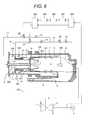
- Fig. 1 shows an entire drawing of the gas turbine unit for power generation having the gas turbine combustor which is the first embodiment of the present invention, and the gas turbine unit includes a compressor 1, a gas turbine combustor 2, and a turbine 3, and by the output of the turbine 3, a generator 4 is rotated, thus power is obtained.
- Compressed air 100 compressed by the compressor 1 flows into the gas turbine combustor 2 via a diffuser 5 and passes between an outer sleeve 6 and a combustor liner 7.
- a part of the compressed air 100 flows into a combustion chamber 8 of the gas turbine combustor 2 as cooling air 101 of the combustor liner 7.
- the compressed air 100 not used as cooling air 101 respectively flows into a diffusion combustion burner 9 arranged on the upstream side of the combustor 2 and on the axial center side of the combustor and a premix combustion burner 10 arranged on the outer circumference side of the diffusion combustion burner 9 as combustion air.
- the diffusion combustion burner 9 installed in the gas turbine combustor 2 includes a fuel nozzle 11 for the diffusion combustion burner and a swirler 12.
- the compressed air 100 flowing in the diffusion combustion burner 9 is swirled by the swirler 12 as diffusion combustion air 102, thereby flows into the combustion chamber 8, burns diffusion burner fuel injected from the fuel nozzle 11 for the diffusion combustion burner, and forms a diffusion flame 103 in the combustion chamber 8.
- the premix combustion burner 10 installed in the gas turbine combustor 2 respectively includes a plurality of fuel nozzles 13 for the premix burner and a flame stabilizer 14.
- the compressed air 100 flowing in the premix combustion burner 10 is mixed and burnt with the premix burner fuel injected from the premix burner fuel nozzles 13 as premix combustion air 104 and forms a premix flame 105 in the combustion chamber 8 on the downstream side of the flame stabilizer 14.
- High-temperature combustion gas 106 generated by the diffusion flame 103 and the premix flame 105 in the combustion chamber 8 passes through a transition piece 15 installed on the downstream side of the gas turbine combustor 2 and flows into the turbine 3.
- the combustion gas 106 drives the turbine 3, permits the generator 4 connected to the turbine 3 to rotate, takes out electric power, and then is discharged from the turbine 3 via the exhaust duct.
- the fuel fed to the gas turbine combustor 2 is fed through a diffusion combustion burner fuel system 17 and a premix combustion burner fuel system 18 which branch from a fuel main pipe 16.
- the fuel main pipe 16, the diffusion combustion burner fuel system 17, and the premix combustion burner fuel system 18 respectively include a dump valve 19 and a control valve 20, thus the ratio of the fuel flow fed to the diffusion combustion burner fuel system 17 and the premix combustion burner fuel system 18 can be controlled.
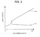
- Fig. 2 shows the relationship between the gas turbine load of the gas turbine combustor 2 of this embodiment and the fuel flow rates of diffusion combustion burner fuel 17a fed to the diffusion combustion burner fuel system 17 and premix combustion burner fuel 18a fed to the premix combustion burner fuel system 18.
- the diffusion combustion burner fuel 17a is fed to the diffusion combustion burner fuel system 17, thereby the gas turbine combustor 2 is switched to the independent diffusion combustion, thus the combustion stability is improved.
- the diffusion combustion burner fuel 17a and the premix combustion burner fuel 18a are respectively fed to the diffusion combustion burner fuel system 17 and the premix combustion burner fuel system 18, and the mixed combustion of the diffusion combustion and premix combustion is realized, thus the NOx emission can be reduced.
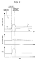
- Fig. 3 shows the changes with time of the diffusion combustion burner fuel flow rate 17a and the premix combustion burner fuel flow rate 18a which are fed to the diffusion combustion burner fuel system 17 and the premix combustion burner fuel system 18, the rotating speed of the gas turbine, and the NOx emission generated in the gas turbine combustor 2 at the time of the load dump of the gas turbine in the control apparatus of the gas turbine combustor 2 of this embodiment.
- a rotating speed of the gas turbine As shown in Fig. 3 as a rotating speed of the gas turbine, if the load dump of the gas turbine occurs, the rotating speed of the gas turbine increases. If the rotating speed of the gas turbine increases excessively, there is a possibility that the compressor 1 or the turbine 3 may be damaged, so it is desirable to suppress the rotating speed of the gas turbine to about 110% of the rated speed at its maximum. Therefore, it is necessary to detect a load dump signal of the gas turbine, simultaneously reduce the fuel flow rate fed to the gas turbine combustor 2 down to the minimum limit at which the gas turbine combustor 2 can maintain the flame, and suppress the rotating speed of the gas turbine from increasing.
- the control apparatus of the gas turbine combustor 2 of this embodiment as shown in Fig. 3 as the diffusion combustion burner fuel flow rate 17a and the premix combustion burner fuel flow rate 18a, if the occurrence of the load dump of the gas turbine is detected by the load dump signal of the gas turbine, the feed of the premix combustion burner fuel 18a via the premix combustion burner fuel system 18 for feeding to the gas turbine combustor 2 is dumped and with respect to the fuel, only the feed of the diffusion combustion burner fuel 17a via the diffusion combustion burner fuel system 17 is performed, and the independent diffusion combustion is switched, thus even at the fuel flow rate of the minimum limit, the combustion stability of the gas turbine combustor 2 is ensured.
- the fuel flow rate fed to the gas turbine combustor 2 is reduced, thus the increased rotating speed of the gas turbine due to the load dump is slowly reduced to the rated rotating speed.
- the rotating speed of the gas turbine is detected by a rotating speed detector 200 for detecting the rotating speed of the gas turbine, and a detection signal of the rotating speed of the gas turbine which is detected by the rotating speed detector 200 is transmitted to a rotating speed recorder 201, and the information of the rotating speed of the gas turbine is preserved by the rotating speed recorder 201.
- the information of the rotating speed of the gas turbine preserved in the rotating speed recorder 201 is sent to a rotating speed trend arithmetic unit 202 and by the rotating speed trend arithmetic unit 202, the change with time of the rotating speed of the gas turbine is calculated.
- the rotating speed trend arithmetic unit 202 detects it by calculating the trend of the change of the rotating speed of the gas turbine on the basis of the value of the rotating speed of the gas turbine recorded in the rotating speed recorder 201 that the rotating speed of the gas turbine increased from the rated rotating speed immediately after the load dump which occurs in the gas turbine starts to reduce from the once-increased rotating speed of the gas turbine, thereby judges the switching of the combustion form of the gas turbine combustor 2.
- control apparatus is structured so that when it is detected by the rotating speed trend arithmetic unit 202 that the once-increased rotating speed of the gas turbine starts to reduce, the rotating speed trend arithmetic unit 202 outputs an instruction signal to a fuel control unit 203 for controlling the flow rate of the fuel to be fed to the gas turbine combustor 2 and the combustion form of the gas turbine combustor 2 is switched from the independent diffusion combustion to the mixed combustion of the diffusion combustion and premix combustion by the fuel control unit 203.
- the fuel control unit 203 receiving the instruction signal for switching the combustion form of the gas turbine combustor 2 from the independent diffusion combustion to the mixed combustion of the diffusion combustion and premix combustion from the rotating speed trend arithmetic unit 202, so as to switch the combustion form of the gas turbine combustor 2 from the independent diffusion combustion to the mixed combustion of the diffusion combustion and premix combustion, controls so as to reduce the diffusion combustion burner fuel flow rate 17a which is fed to the diffusion combustion burner 9 of the gas turbine combustor 2 via the diffusion combustion burner fuel system 17 and increase the premix combustion burner fuel flow rate 18a which is fed to the premix combustion burner 10 via the premix combustion burner fuel system 18.
- the fuel flow rate is regulated and the gas turbine is controlled so as to enter the full speed no-load operation.
- the NOx emission generated from the gas turbine combustor 2 can be reduced.
- the reliability of the gas turbine combustor 2 can be improved. Namely, in the diffusion combustion of the gas turbine combustor 2, a flame is formed in a mixing state close to the stoichiometric ratio of fuel to air, so that compared with the premix combustion, a local flame temperature becomes high.
- the combustion form of the gas turbine combustor 2 is promptly switched from the independent diffusion combustion to the mixed combustion of the diffusion combustion and premix combustion, so that a heat load generated by combustion can be diffused to the diffusion combustion burner 9 and the premix combustion burner 10.
- the combustion form of the gas turbine combustor 2 is switched from the independent diffusion combustion to the mixed combustion of the diffusion combustion and premix combustion, thus after ignition of the premix combustion burner 10, the metal temperature of the diffusion combustion burner 9 is reduced and even in the full speed no-load operation state, the metal temperature of the diffusion combustion burner 9 can be suppressed low, so that the reliability of the diffusion combustion burner 9 can be improved.
- the temperature of the premix combustion burner 10 rises when the combustion form is switched from the independent diffusion combustion to the mixed combustion of the diffusion combustion and premix combustion, though the premix combustion burner fuel flow rate 18a fed to the premix combustion burner 10 via the premix combustion burner fuel system 18 is sufficiently low compared with the rated load condition, so that the metal temperature of the premix combustion burner 10 is low and the gas turbine combustor 2 creates no trouble in reliability.
- a method and an apparatus for controlling a gas turbine combustor capable of ensuring combustion stability immediately after the load dump of the gas turbine and reducing the NOx emission due to the full speed no-load operation after the load dump can be realized.
- the control apparatus of the gas turbine combustor and the control method of the gas turbine combustor of the second embodiment of the present invention will be explained by referring to Figs. 4 and 5 .
- the control apparatus of the gas turbine combustor 2 of the second embodiment of the present invention is the same as that of the gas turbine combustor 2 of the first embodiment shown in Figs. 1 to 3 in the basic constitution, so that the explanation common to the two is omitted and only the different portions will be explained below.
- Fig. 4 shows an entire drawing of the gas turbine unit for power generation including the gas turbine combustor 2 which is the second embodiment of the present invention and the control apparatus of the gas turbine combustor 2 of this embodiment, in addition to the constitution of the gas turbine combustor 2 of the first embodiment, is structured so as to install a rotating speed comparison arithmetic unit 204 for comparing a set switching rotating speed with information of the recorder 201 for recording the rotating speed of the gas turbine and a logic circuit 205 for deciding signals of the rotating speed trend arithmetic unit 202 and the rotating speed comparison arithmetic unit 204.
- a rotating speed comparison arithmetic unit 204 for comparing a set switching rotating speed with information of the recorder 201 for recording the rotating speed of the gas turbine
- a logic circuit 205 for deciding signals of the rotating speed trend arithmetic unit 202 and the rotating speed comparison arithmetic unit 204.
- the combustion form of the gas turbine combustor 2 is switched from the independent diffusion combustion to the mixed combustion of the diffusion combustion and premix combustion. Therefore, at the time of ignition of the premix flame 105 formed in the combustion chamber 8 of the gas turbine combustor 2, the premix flame 105 becomes unstable transiently and there is a possibility of flame loss.
- control apparatus of the gas turbine combustor 2 of this embodiment is structured so as to install the rotating speed comparison arithmetic unit 204 for comparing the switching rotating speed for switching the combustion form from the independent diffusion combustion to the mixed combustion of the diffusion combustion and premix combustion with the information of the rotating speed of the gas turbine recorded in the recorder 201 and the logic circuit 205 for deciding signals of the rotating speed trend arithmetic unit 202 and the rotating speed comparison arithmetic unit 204.
- Fig. 5 shows the changes with time of the diffusion combustion burner fuel flow rate 17a and the premix combustion burner fuel flow rate 18a which are fed to the diffusion combustion burner fuel system 17 and the premix combustion burner fuel system 18, the rotating speed of the gas turbine, and the NOx emission generated in the gas turbine combustor 2 at the time of load dump of the gas turbine in the control apparatus of the gas turbine combustor 2 of this embodiment.
- the rotating speed comparison arithmetic unit 204 compares a preset switching rotating speed ⁇ p with the information of the rotating speed of the recorder 201 and when the rotating speed of the gas turbine increased after the load dump reduces to the switching rotating speed ⁇ p or lower, transmits a signal to the logic circuit 205.
- the switching rotating speed ⁇ p is within the range from the rated rotating speed to 110% of the rated rotating speed and it is desirable to set the rotating speed of the gas turbine so that even if the combustion form of the gas turbine combustor 2 is switched from the independent diffusion combustion to the mixed combustion of the diffusion combustion and premix combustion, the premix flame 105 formed in the combustion chamber 8 of the gas turbine combustor 2 burns stably.
- the logic circuit 205 decides the signals output from the rotating speed trend arithmetic unit 202 and the rotating speed comparison arithmetic unit 204 and only upon receipt of both of an output signal from the rotating speed trend arithmetic unit 202 when the rotating speed of the gas turbine which is increased once due to the load dump starts to reduce and a signal of the rotating speed of the gas turbine of the switching rotating speed ⁇ p or lower output from the rotating speed comparison arithmetic unit 204, transmits an operation signal from the logic circuit 205 to the fuel control unit 203.
- the fuel control unit 203 receives the operation signal from the logic circuit 205 and so the combustion form of the gas turbine combustor 2 is switched from the independent diffusion combustion to the mixed combustion of the diffusion combustion and premix combustion, controls so as to reduce the diffusion combustion burner fuel flow rate 17a which is fed via the diffusion combustion burner fuel system 17 and increase the premix combustion burner fuel flow rate 18a which is fed via the premix combustion burner fuel system 18.
- the control apparatus of the gas turbine combustor 2 of this embodiment is structured as mentioned above, thus when the rising width of the rotating speed of the gas turbine at the time of the load dump of the gas turbine is wide, after the rotating speed of the gas turbine reduces down to the switching rotating speed ⁇ p , the combustion form of the gas turbine combustor 2 is switched from the independent diffusion combustion to the mixed combustion of the diffusion combustion and premix combustion, so that the premix flame 105 formed in the combustion chamber 8 of the gas turbine combustor 2 can be ignited stably and can be prevented from flame loss.
- a method and an apparatus for controlling a gas turbine combustor capable of ensuring combustion stability immediately after the load dump of the gas turbine and reducing the NOx emission due to the full speed no-load operation after the load dump can be realized.
- the control apparatus of the gas turbine combustor and the control method of the gas turbine combustor of the third embodiment of the present invention will be explained by referring to Figs. 6 and 7 .
- the control apparatus of the gas turbine combustor 2 of the third embodiment of the present invention is the same as that of the gas turbine combustor 2 of the first embodiment shown in Figs. 1 to 3 in the basic constitution, so that the explanation common to the two is omitted and only the different portions will be explained below.
- Fig. 6 shows an entire drawing of the gas turbine unit for power generation including the gas turbine combustor 2 which is the third embodiment of the present invention and the gas turbine combustor 2 of this embodiment, in addition to the constitution of the gas turbine combustor 2 of the first embodiment, is structured so as to install a switching rotating speed arithmetic unit 206 for calculating the rotating speed of the gas turbine to switch the combustion form of the gas turbine combustor 2 from the independent diffusion combustion to the mixed combustion of the diffusion combustion and premix combustion from the information of the recorder 201 for recording the rotating speed of the gas turbine after the load dump of the gas turbine.
- a switching rotating speed arithmetic unit 206 for calculating the rotating speed of the gas turbine to switch the combustion form of the gas turbine combustor 2 from the independent diffusion combustion to the mixed combustion of the diffusion combustion and premix combustion from the information of the recorder 201 for recording the rotating speed of the gas turbine after the load dump of the gas turbine.
- Fig. 7 shows the changes with time of the diffusion combustion burner fuel flow rate 17a and the premix combustion burner fuel flow rate 18a which are fed via the diffusion combustion burner fuel system 17 and the premix combustion burner fuel system 18 at the time of load dump of the gas turbine in the control apparatus of the gas turbine combustor 2 of this embodiment, the rotating speed of the gas turbine, and the NOx emission generated in the gas turbine combustor 2.
- the rotating speed of the gas turbine increased from the rated rotating speed in correspondence to the load dump of the gas turbine, if the fuel flow rate fed to the gas turbine combustor 2 reduces, starts to reduce.
- the switching rotating speed arithmetic unit 206 receiving the signal of detecting that the rotating speed of the gas turbine starts to reduce from the rotating speed trend arithmetic unit 202, by a built-in arithmetic unit, from the maximum rotating speed ⁇ max of the gas turbine recorded in the rotating speed recorder 201, on the basis of Formulas (1) and (2) indicated below, calculates a fuel control switching rotating speed ⁇ c .
- ⁇ max indicates a maximum rotating speed after the load dump and ⁇ fs indicates a rated rotating speed.
- ⁇ indicates a constant and it is a value within the range indicated in Formula (2). 0 ⁇ ⁇ ⁇ 1
- the switching rotating speed arithmetic unit 206 transmits the fuel control switching rotating speed ⁇ c calculated by the built-in calculator on the basis of Formulas (1) and (2) to the fuel control unit 203 as information of the switching rotating speed ⁇ c .
- the fuel control unit 203 receiving the information from the switching rotating speed arithmetic unit 206, in the switching rotating speed ⁇ c , so that the switching of the combustion form of the gas turbine combustor 2 from the independent diffusion combustion to the mixed combustion of the diffusion combustion and premix combustion is completed, as shown in Fig. 7 , in accordance with the reduction in the rotating speed of the gas turbine, controls so as to reduce the diffusion combustion burner fuel flow rate 17a which is fed via the diffusion combustion burner fuel system 17 of the gas turbine combustor 2 and increase the premix combustion burner fuel flow rate 18a which is fed via the premix combustion burner fuel system 18 of the gas turbine combustor 2.
- a fuel flow ratio F d of the diffusion combustion burner fuel fed to the diffusion combustion burner fuel system 17 and a fuel flow ratio Fp of the diffusion combustion burner fuel fed to the premix combustion burner fuel system 18, using the maximum rotating speed ⁇ max , the fuel control switching rotating speed ⁇ c , the rotating speed ⁇ detected by the rotating speed detector 200, and a fuel flow ratio F d1 of the diffusion combustion burner fuel after switching, are calculated from Formulas (3), (4), and (5) indicated below.
- the control apparatus of the gas turbine combustor 2 of this embodiment is structured as mentioned above, thus the reliability when switching the combustion form of the gas turbine combustor 2 from the independent diffusion combustion to the mixed combustion of the diffusion combustion and premix combustion can be improved.
- the control apparatus of the gas turbine combustor 2 of this embodiment by use of the aforementioned constitution, in accordance with the rotating speed of the gas turbine, switches the combustion form of the gas turbine combustor 2 from the independent diffusion combustion to the mixed combustion of the diffusion combustion and premix combustion, so that when the rotating speed of the gas turbine is high, the diffusion combustion ratio of high stability increases, and the flame stability is ensured, and when the rotating speed of the gas turbine reduces, the premix combustion ratio increases, thus the NOx emission generated by the gas turbine combustor 2 can be reduced.
- a method and an apparatus for controlling a gas turbine combustor capable of ensuring combustion stability immediately after the load dump of the gas turbine and reducing the NOx emission due to the full speed no-load operation after the load dump can be realized.
- the control apparatus of the gas turbine combustor and the control method of the gas turbine combustor of the fourth embodiment of the present invention will be explained by referring to Figs. 9 and 10 .
- the control apparatus of the gas turbine combustor 2 of the fourth embodiment of the present invention is the same as that of the gas turbine combustor 2 of the first embodiment shown in Figs. 1 to 3 in the basic constitution, so that the explanation common to the two is omitted and only the different portions will be explained below.
- Fig. 9 shows an entire drawing of the gas turbine unit for power generation including the gas turbine combustor 2 which is the fourth embodiment of the present invention and the gas turbine combustor 2 of this embodiment, in addition to the constitution of the gas turbine combustor 2 of the first embodiment, is structured so as to install a bleed valve on-off detector 207 for detecting opening or closing of a bleed valve 21 installed in the compressor 1 and a logic circuit 208 for deciding bleed valve on-off signals detected respectively by the bleed valve on-off detector 207 and the rotating speed detector 200 of the gas turbine and a detection signal of the rotating speed of the gas turbine.
- a bleed valve on-off detector 207 for detecting opening or closing of a bleed valve 21 installed in the compressor 1
- a logic circuit 208 for deciding bleed valve on-off signals detected respectively by the bleed valve on-off detector 207 and the rotating speed detector 200 of the gas turbine and a detection signal of the rotating speed of the gas turbine.
- the bleed valve 21 installed in the compressor 1 is installed in the middle of the flow path for connecting the intermediate stage of the compressor 1 and the exhaust duct, and the bleed valve 21 is opened, and a part of the compressed air 100 compressed by the compressor 1 is permitted to escape into the exhaust duct, thus in the start-up and acceleration processes of the gas turbine, the compressor 1 is prevented from surging.
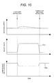
- Fig. 10 As the rotating speed of the gas turbine, an opening angle 21a of the bleed valve 21, and a compressed air flow rate 100a of the compressor 1 are respectively shown in Fig. 10 , at the time of load dump of the gas turbine, the flow rate of the compressed air 100 flowing into the turbine 3 is reduced and the increase in the rotating speed of the gas turbine is suppressed, so that the opening angle 21a of the bleed valve 21 is controlled so as to be totally opened simultaneously with the load dump.
- the opening angle 21a of the bleed valve 21 is operated so as to be totally closed.
- the flow rate 100a of the compressed air 100 flowing into the gas turbine combustor 2 increases, so that when the combustion form of the gas turbine combustor 2 is the mixed combustion of the diffusion combustion and premix combustion, on the downstream side of the premix combustion burner 10, the mixing ratio of fuel and air is lowered, and the premix flame 105 formed in the combustion chamber 8 of the gas turbine combustor 2 becomes unstable, and there is a possibility of flame loss.
- the control apparatus of the gas turbine combustor 2 of this embodiment shown in Fig. 9 calculates the change with time of the rotating speed of the gas turbine by the rotating speed trend arithmetic unit 202 and checks, by the logic circuit 8, an on-off signal of the bleed valve 21 detected by the bleed valve on-off detector 207 and a change with time signal of the rotating speed of the gas turbine calculated by the rotating speed trend arithmetic unit 202.
- the logic circuit 208 when the condition that the bleed valve 21 is totally closed after the load dump of the gas turbine and the rotating speed of the gas turbine starts to reduce is effected, outputs an instruction signal to the fuel control unit 201.
- the fuel control unit 201 upon receipt of the instruction signal from the logic circuit 208, so that the combustion form of the gas turbine combustor 2 is switched from the independent diffusion combustion to the mixed combustion of the diffusion combustion and premix combustion, controls so as to reduce the diffusion combustion burner fuel flow rate 17a which is fed to the diffusion combustion burner 9 of the gas turbine combustor 2 via the diffusion combustion burner fuel system 17 and increase the premix combustion burner fuel flow rate 18a which is fed to the premix combustion burner 10 via the premix combustion burner fuel system 18.
- the control apparatus of the gas turbine combustor 2 of this embodiment is structured as mentioned above, thus after completion of the totally closing operation of the bleed valve 21 installed in the compressor 1, the combustion form of the gas turbine combustor 2 can be switched to the mixed combustion of the diffusion combustion and premix combustion. Therefore, by the totally closing operation of the bleed valve 21, the premix flame 105 formed in the combustion chamber 8 of the gas turbine combustor 2 can be prevented from becoming unstable and losing the flame.
- a method and an apparatus for controlling a gas turbine combustor capable of ensuring combustion stability immediately after the load dump of the gas turbine and reducing the NOx emission due to the full speed no-load operation after the load dump can be realized.
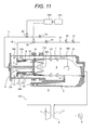
- the control apparatus of the gas turbine combustor and the control method of the gas turbine combustor of the fifth embodiment of the present invention will be explained by referring to Fig. 11 .
- the control apparatus of the gas turbine combustor 2 of the fifth embodiment of the present invention is the same as that of the gas turbine combustor 2 of the first embodiment shown in Figs. 1 to 3 in the basic constitution, so that the explanation common to the two is omitted and only the different portions will be explained below.
- Fig. 11 shows an entire drawing of the gas turbine including the gas turbine combustor of the fifth embodiment of the present invention and the control apparatus of the gas turbine combustor 2 of this embodiment is structured so as to install, in place of the rotating speed detector 200 of the gas turbine installed in the gas turbine combustor 2 of the first embodiment, a timer circuit 209 for transmitting a signal to the fuel control unit 203 after a predetermined period of time from the load dump of the gas turbine.
- the timer circuit 209 receiving the load dump signal of the gas turbine transmits a signal to the fuel control unit 203 after the predetermined period of time from the load dump.
- the timer circuit 209 is structured so as to preset the time required for the rotating speed of the gas turbine to increase once due to the load dump of the gas turbine to reduce on a level free of trouble even if the combustion form of the gas turbine combustor 2 is switched from the independent diffusion combustion to the mixed combustion of the diffusion combustion and premix combustion and output a signal after the preset time elapses from the load dump.
- the fuel control unit 203 receiving the output signal from the timer circuit 209, so that the combustion form of the gas turbine combustor 2 is switched from the independent diffusion combustion to the mixed combustion of the diffusion combustion and premix combustion, controls so as to reduce the diffusion combustion burner fuel flow rate 17a which is fed to the diffusion combustion burner 9 of the gas turbine combustor 2 via the diffusion combustion burner fuel system 17 and increase the premix combustion burner fuel flow rate 18a which is fed to the premix combustion burner 10 via the premix combustion burner fuel system 18.
- the signal delay time set in the timer circuit 209 should preferably be a sufficient period of time for the rotating speed of the gas turbine increased from the rated rotating speed due to the load dump of the gas turbine to reduce again down to the rated rotating speed and a short period of time as possible to reduce the NOx emission in the independent diffusion combustion of the gas turbine combustor 2 and concretely, should preferably be about 30 seconds.
- the control apparatus of the gas turbine combustor 2 of this embodiment is structured as mentioned above, thus a similar effect to that of the gas turbine combustor 2 of Embodiment 1 can be reproduced by the simple timer circuit 209, and the control logic is simplified, thus the cost of the control apparatus can be decreased.
- a method and an apparatus for controlling a gas turbine combustor capable of ensuring combustion stability immediately after the load dump of the gas turbine and reducing the NOx emission due to the full speed no-load operation after the load dump can be realized.
- the control apparatus of the gas turbine combustor and the control method of the gas turbine combustor of the sixth embodiment of the present invention will be explained by referring to Figs. 12 and 13 .
- the control apparatus of the gas turbine combustor 2 of the sixth embodiment of the present invention is the same as that of the gas turbine combustor 2 of the first embodiment shown in Figs. 1 to 3 in the basic constitution, so that the explanation common to the two is omitted and only the different portions will be explained below.
- Fig. 12 shows an entire drawing of the gas turbine unit for power generation including the gas turbine combustor 2 that is the sixth embodiment of the present invention and this embodiment is an embodiment when the control apparatus of the gas turbine combustor 2 having the aforementioned constitution is applied to a biaxial gas turbine unit.
- the biaxial gas turbine unit is a biaxial gas turbine that the axis for connecting the compressor 1 and a high pressure turbine 22 and the axis for connecting the generator 4 and a low pressure turbine 23 are two separated axes.
- the gas turbine combustor 2 of this embodiment includes the detector 200 for detecting the rotating speed of the gas turbine in the low pressure turbine 23.
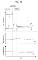
- Fig. 13 shows, at the time of the load dump of the gas turbine in the control apparatus of the gas turbine combustor 2 of this embodiment, the changes with time of the diffusion combustion burner fuel flow rate 17a and the premix combustion burner fuel flow rate 18a which are fed via the diffusion combustion burner fuel system 17 and the premix combustion burner fuel system 18 and the changes with time of a turbine rotating speed 23a of the low pressure turbine 23 and a turbine rotating speed 22a of the high pressure turbine 22.
- the turbine rotating speed 23a of the low pressure turbine 23 connected to the generator 4 increases, so that to suppress the increase in the rotating speed of the low pressure turbine 23, the fuel flow rate fed to the gas turbine combustor 2 is reduced and the combustion form is switched to the independent diffusion combustion.
- the fuel flow rate fed to the gas turbine combustor 2 is reduced, thus the rotating speed 23a of the low pressure turbine 23 is slowly reduced down to the rated rotating speed.
- a detection signal of the turbine rotating speed of the low pressure turbine 23 detected by the rotating speed detector 200 is transmitted to the recorder 201 and the information of the rotating speed of the low pressure turbine 23 is preserved by the recorder 201. From the information of the rotating speed of the low pressure turbine preserved in the recorder 201, the change with time of the rotating speed of the low pressure turbine is calculated by the rotating speed trend arithmetic unit 202.
- the fuel control unit 203 receiving the signal transmitted from the rotating speed trend arithmetic unit 202, so that the combustion form of the gas turbine combustor 2 is switched from the independent diffusion combustion to the mixed combustion of the diffusion combustion and premix combustion, controls so as to reduce the diffusion combustion burner fuel flow rate 17a which is fed to the diffusion combustion burner 9 of the gas turbine combustor 2 via the diffusion combustion burner fuel system 17 and increase the premix combustion burner fuel flow rate 18a which is fed to the premix combustion burner 10 via the premix combustion burner fuel system 18.
- the high pressure turbine 22 serves as a function of driving the compressor 1, so that the fuel flow rate reduces after the load dump of the gas turbine, thus the rotating speed reduces slowly. Therefore, when the rotating speed 23a of the low pressure turbine 23 increases once, then starts to reduce, and approaches the rated rotating speed, so as to switch the combustion form of the gas turbine combustor 2 from the independent diffusion combustion to the mixed combustion of the diffusion combustion and premix combustion, increase the diffusion combustion burner fuel flow rate 17a and the premix combustion burner fuel flow rate 18a which are fed to the diffusion combustion burner fuel system 17 and the premix combustion burner fuel system 18, and increase again the rotating speed 22a of the high pressure turbine 22 up to the rated rotating speed, the fuel flow rate is controlled by the fuel control unit 203.
- the control apparatus of the gas turbine combustor 2 is structured as this embodiment, thus even in the biaxial gas turbine unit, the combustion form can be promptly switched from the independent diffusion combustion to the mixed combustion of the diffusion combustion and premix combustion after the load dump of the gas turbine and the NOx emission in the full speed no-load operation state can be reduced.
- a method and an apparatus for controlling a gas turbine combustor capable of ensuring combustion stability immediately after the load dump of the gas turbine and reducing the NOx emission due to the full speed no-load operation after the load dump can be realized.
- the present invention can be applied to the gas turbine combustor.
Landscapes
- Engineering & Computer Science (AREA)
- Chemical & Material Sciences (AREA)
- Combustion & Propulsion (AREA)
- Mechanical Engineering (AREA)
- General Engineering & Computer Science (AREA)
- Control Of Turbines (AREA)
- Regulation And Control Of Combustion (AREA)
Abstract
Description
- The present invention relates to a method and an apparatus for controlling a gas turbine combustor.
- In the gas turbine combustor, there are a diffusion combustor and a premix combustor available. The diffusion combustor is a system for separately feeding and burning fuel and air in a combustion chamber, and a flame is formed in a state close to the stoichiometric ratio of fuel to air, and the local flame temperature rises, so that although the combustion stability is high, the nitrogen oxide (NOx) emission increases.
- On the other hand, the premix combustor is a system for premixing fuel and air and then feeding and burning them in the combustion chamber, and the mixing ratio of fuel and air on the flame sheet is lower than that in the diffusion combustion, and the local flame temperature is lowered, so that the emission of NOx can be reduced.
- As general use of a low NOx combustor, at the time of a low load operation from start up to acceleration, the diffusion combustion of high combustion stability is used and at the time of the base load operation from a partial load, the diffusion combustion of high combustion stability and the premix combustion capable of reducing the NOx emission are combined, thus the combustion stability and the reduction in the NOx discharging rate are compatible with each other.
- When using the gas turbine for power generation, the gas turbine needs to withstand a load dump when the load operation state is transferred to the no-load operation state due to separation of the generator from the gas turbine. The load dump is to urgently separate the generator and turbine from each other from some cause and in this case, the gas turbine needs to immediately enter the full speed no-load operation state.
- Immediately after the load dump, the rotating speed of the gas turbine increases. If the rotating speed of the gas turbine increases to the limit value or higher, there is a concern that it may lead to damage to the compressor or turbine and it is necessary to promptly reduce the fuel flow rate to the minimum limit capable of maintaining the flame by the gas turbine combustor, thereby suppressing an increase in the rotating speed of the gas turbine.
- Due to the increase in the rotating speed of the gas turbine in correspondence to the load dump, the flow rate of compressed air flowing into the gas turbine combustor increases, and the fuel flow rate reduces suddenly, so that the inner state of the gas turbine combustor is transiently greatly changed. Therefore, in the gas turbine combustor, high combustion stability is required, and when reducing the fuel flow rate at the time of load dump, so as to dump the fuel for premix combustion, thereby switch to the independent diffusion combustion, the fuel flow rate is controlled.
- In Japanese Patent Laid-open No.
Hei 10(1998)-169467 - Patent Document 1: Japanese Patent Laid-open No.
Hei 10(1998)-169467 - The regulation and social demands on the environment become stronger day by day and also in the gas turbine combustor, a further reduction in the NOx emission is required. In the base load operation state from the partial load of the gas turbine, the combustion of the gas turbine combustor is switched to the mixed combustion of the diffusion combustion and premix combustion, thus the NOx emission rate can be reduced.
- Further, in the gas turbine, to suppress the increase in the rotating speed due to the load dump, the fuel for the premix combustion is dumped at the time of load dump and so as to switch to the independent diffusion combustion, the fuel flow rate fed to the gas turbine combustor is controlled.
- In Japanese Patent Laid-open No.
Hei 10(1998)-169467 - When the full speed no-load operation state after the load dump is held for many hours, the independent diffusion combustion state of a high NOx emission is continued, so that an increase in the NOx emission due to the full speed no-load operation state after the load dump causes a problem.
- An object of the present invention is to provide a method and an apparatus for controlling a gas turbine combustor capable of ensuring combustion stability immediately after load dump of the gas turbine and reducing the NOx emission due to full speed no-load operation after the load dump.
- An apparatus for controlling a gas turbine combustor having a diffusion combustion burner and a premix combustion burner comprising: a rotating speed detector for detecting a rotating speed of gas turbine, a recorder for recording the detected value of the rotating speed of gas turbine detected by the rotating speed detector, an arithmetic unit for calculating a change with time of the rotating speed of gas turbine in accordance with details of the detected value of the rotating speed of gas turbine recorded in the recorder, and a fuel control unit for judging a starting situation of reduction in the rotating speed of gas turbine on the basis of the change with time of the rotating speed of gas turbine calculated by the arithmetic unit and controlling respectively a fuel flow rate for the diffusion combustion burner to be fed to the diffusion combustion burner installed in the gas turbine combustor and a fuel flow rate for the premix combustion to be fed to the premix combustion burner.
- An apparatus for controlling a gas turbine combustor having a diffusion combustion burner and a premix combustion burner comprising: a detector for detecting a rotating speed of gas turbine, a recorder for recording the detected value of the rotating speed of gas turbine detected by the rotating speed detector, an arithmetic unit for calculating a change with time of the rotating speed of gas turbine in accordance with details of the detected value of the rotating speed of gas turbine recorded in the recorder, a bleed valve opening angle detector for detecting an opening angle of a compressor bleed valve installed in a compressor, a logic circuit for checking a value of the change with time of the rotating speed of gas turbine calculated by the arithmetic unit and an opening angle signal of the bleed valve detected by the bleed valve opening angle detector, and a fuel control unit for respectively controlling a fuel flow rate for the diffusion combustion burner to be fed to the diffusion combustion burner installed in the gas turbine combustor and a fuel flow rate for the premix combustion to be fed to the premix combustion burner so as to switch a combustion state of the gas turbine combustor from independent diffusion combustion by the diffusion combustion burner to mixed combustion of diffusion combustion and premix combustion by the diffusion combustion burner and the premix combustion burner on the basis of check results by the logic circuit.
- An apparatus for controlling a gas turbine combustor having a diffusion combustion burner and a premix combustion burner comprising: a fuel control unit for respectively controlling a fuel flow rate for the diffusion combustion burner to be fed to the diffusion combustion burner installed in the gas turbine combustor and a fuel flow rate for the premix combustion to be fed to the premix combustion burner so as to switch a combustion state of the gas turbine combustor from independent diffusion combustion by the diffusion combustion burner to mixed combustion of diffusion combustion and premix combustion by the diffusion combustion burner and the premix combustion burner on the basis of a signal transmitted from a timer circuit, which is installed to transmit a signal for controlling the fuel control unit after a predetermined period of time after receipt of a load dump signal of gas turbine, after a predetermined period of time.
- A method for controlling a gas turbine combustor including a diffusion combustion burner and a premix combustion burner, comprising the steps of: detecting a rotating speed of gas turbine, recording the detected value of the rotating speed of gas turbine, calculating a change with time of the rotating speed of gas turbine in accordance with details of the recorded detected value of the rotating speed of gas turbine, judging a starting situation of reduction in the rotating speed of gas turbine on the basis of the calculated change with time of the rotating speed of gas turbine, and regulating a fuel flow rate fed to the gas turbine combustor controls respectively a fuel flow rate for the diffusion combustion burner to be fed to the diffusion combustion burner installed in the gas turbine combustor and a fuel flow rate for the premix combustion to be fed to the premix combustion burner.
- A method for controlling a gas turbine combustor including a diffusion combustion burner and a premix combustion burner, comprising the steps of: detecting a rotating speed of a gas turbine, recording the detected value of the rotating speed of gas turbine, calculating a change with time of the rotating speed of gas turbine in accordance with details of the recorded detected value of the rotating speed of gas turbine, detecting an opening angle of a compressor bleed valve installed in a compressor, and regulating a fuel flow rate fed to the gas turbine combustor on the basis of check results of a calculated value of the change with time of the rotating speed of gas turbine and a detected opening angle signal of the bleed valve respectively controls a fuel flow rate for the diffusion combustion burner to be to the diffusion combustion burner installed in the gas turbine combustor and a fuel flow rate for the premix combustion to be fed to the premix combustion burner so as to switch a combustion state of the gas turbine combustor from independent diffusion combustion by the diffusion combustion burner to mixed combustion of the diffusion combustion and the premix combustion by the diffusion combustion burner and the premix combustion burner.
- A method for controlling a gas turbine combustor having a diffusion combustion burner and a premix combustion burner, comprising the steps of: controlling a fuel flow rate for the diffusion combustion burner to be fed to the diffusion combustion burner installed in the gas turbine combustor and a fuel flow rate for the premix combustion to be fed to the premix combustion burner respectively so as to switch a combustion state of the gas turbine combustor from independent diffusion combustion by the diffusion combustion burner to mixed combustion of the diffusion combustion and the premix combustion by the diffusion combustion burner and the premix combustion burner on the basis of a signal transmitted from a timer circuit, which is installed to transmit a signal for controlling the fuel control unit after a predetermined period of time after receipt of a load dump signal of gas turbine, after a predetermined period of time.
- According to the present invention, a method and an apparatus for controlling a gas turbine combustor capable of ensuring combustion stability immediately after load dump of the gas turbine and reducing the NOx emission due to full speed no-load operation after the load dump can be realized.
-
-
Fig. 1 is a block diagram of the gas turbine unit including the gas turbine combustor that is the first embodiment of the present invention, -
Fig. 2 is a characteristic diagram showing the fuel flow rate of the gas turbine combustor that is the first embodiment of the present invention and the load of the gas turbine, -
Fig. 3 is a characteristic diagram showing the changes with time of the fuel flow rate of the diffusion combustion burner, the fuel flow rate of the premix combustion burner, the rotating speed of the gas turbine, and the NOx emission at the time of load dump in the first embodiment of the present invention, -
Fig. 4 is a block diagram of the gas turbine unit including the gas turbine combustor that is the second embodiment of the present invention, -
Fig. 5 is a characteristic diagram showing the changes with time of the fuel flow rate of the diffusion combustion burner, the fuel flow rate of the premix combustion burner, the rotating speed of the gas turbine, and the NOx emission at the time of load dump in the second embodiment of the present invention, -
Fig. 6 is a block diagram of the gas turbine unit including the gas turbine combustor that is the third embodiment of the present invention, -
Fig. 7 is a characteristic diagram showing the changes with time of the fuel flow rate of the diffusion combustion burner, the fuel flow rate of the premix combustion burner, the rotating speed of the gas turbine, and the NOx emission at the time of load dump in the third embodiment of the present invention, -
Fig. 8 is a characteristic diagram showing the relationship between the rotating speed of the gas turbine and the fuel flow ratio at the time of load dump in the third embodiment of the present invention, -
Fig. 9 is a block diagram of the gas turbine unit including the gas turbine combustor that is the fourth embodiment of the present invention, -
Fig. 10 is a characteristic diagram showing the rotating speed of the gas turbine, the opening angle of the bleed valve, and the flow rate of compressed air at the time of load dump in the fourth embodiment of the present invention, -
Fig. 11 is a block diagram of the gas turbine unit including the gas turbine combustor that is the fifth embodiment of the present invention, -
Fig. 12 is a block diagram of the gas turbine unit including the gas turbine combustor which is the sixth embodiment of the present invention, and -
Fig. 13 is a characteristic diagram showing the fuel flow rate, the rotating speed of the low-pressure turbine, and the rotating speed of the high-pressure turbine at the time of load dump in the sixth embodiment of the present invention. - A control apparatus for controlling a gas turbine combustor that is an embodiment of the present invention will be explained below with reference to the accompanying drawings.
- When using the gas turbine for power generation, the gas turbine needs to withstand the load dump of the gas turbine transferring from the load operation state to the no-load operation state by separating the generator from the gas turbine.
- At the time of the load dump of the gas turbine, it is necessary to promptly reduce the fuel flow rate down to the minimum limit at which the gas turbine combustor can maintain the flame and prevent the compressor and gas turbine from damage due to an increase in the rotating speed of the gas turbine up to the limit value or higher.
- Due to the increase in the rotating speed of the gas turbine in correspondence to the load dump, the flow rate of compressed air flowing into the gas turbine combustor increases, and the fuel flow rate reduces suddenly, so that the inner state of the gas turbine combustor is greatly changed transiently. Therefore, the gas turbine combustor is required for high combustion stability, so that when reducing the fuel flow rate at the time of the load dump of the gas turbine, fuel is controlled so as to dump the premix fuel and switch to the independent diffusion combustion.
- On the other hand, if the combustion of the gas turbine combustor is switched from the premix combustion to the independent diffusion combustion, the NOx emission due to the full speed no-load operation after the load dump increases.
- Therefore, the control apparatus of the gas turbine combustor of the present invention includes the detector for detecting the rotating speed of the gas turbine, the recorder for recording a signal of the detector, the arithmetic unit for calculating the change with time of the rotating speed from the information of the recorder, and the fuel control unit, upon receipt of a signal from the arithmetic unit, for controlling the fuel flow rates to be fed to the diffusion combustion burner and premix combustion burner of the gas turbine combustor and is structured so as to output an operation signal to the fuel control unit from the arithmetic unit if the rotating speed of the gas turbine increased from the rated rotating speed due to the load dump of the gas turbine starts to reduce from the increased rotating speed of the gas turbine and control the fuel flow rate fed to the gas turbine combustor so as to switch the independent diffusion combustion to the mixed combustion of the diffusion combustion and premix combustion.
- The control apparatus of the gas turbine combustor is structured as mentioned above, thus if the rotating speed of the gas turbine increased from the rated rotating speed after the load dump of the gas turbine starts to reduce, the independent diffusion combustion can be promptly switched to the mixed combustion of the diffusion combustion and premix combustion, so that the NOx emission due to the full speed no-load operation after the load dump can be reduced.
- The control apparatus of the gas turbine combustor and the control method of the gas turbine combustor of the first embodiment of the present invention will be explained by referring to
Figs. 1 to 3 . -
Fig. 1 shows an entire drawing of the gas turbine unit for power generation having the gas turbine combustor which is the first embodiment of the present invention, and the gas turbine unit includes acompressor 1, agas turbine combustor 2, and aturbine 3, and by the output of theturbine 3, agenerator 4 is rotated, thus power is obtained. - Compressed
air 100 compressed by thecompressor 1 flows into thegas turbine combustor 2 via adiffuser 5 and passes between anouter sleeve 6 and acombustor liner 7. - A part of the
compressed air 100 flows into acombustion chamber 8 of thegas turbine combustor 2 ascooling air 101 of thecombustor liner 7. Thecompressed air 100 not used ascooling air 101 respectively flows into adiffusion combustion burner 9 arranged on the upstream side of thecombustor 2 and on the axial center side of the combustor and apremix combustion burner 10 arranged on the outer circumference side of thediffusion combustion burner 9 as combustion air. - The
diffusion combustion burner 9 installed in thegas turbine combustor 2 includes afuel nozzle 11 for the diffusion combustion burner and aswirler 12. Thecompressed air 100 flowing in thediffusion combustion burner 9 is swirled by theswirler 12 asdiffusion combustion air 102, thereby flows into thecombustion chamber 8, burns diffusion burner fuel injected from thefuel nozzle 11 for the diffusion combustion burner, and forms adiffusion flame 103 in thecombustion chamber 8. - The
premix combustion burner 10 installed in thegas turbine combustor 2 respectively includes a plurality offuel nozzles 13 for the premix burner and aflame stabilizer 14. Thecompressed air 100 flowing in thepremix combustion burner 10 is mixed and burnt with the premix burner fuel injected from the premixburner fuel nozzles 13 aspremix combustion air 104 and forms apremix flame 105 in thecombustion chamber 8 on the downstream side of theflame stabilizer 14. - High-
temperature combustion gas 106 generated by thediffusion flame 103 and thepremix flame 105 in thecombustion chamber 8 passes through atransition piece 15 installed on the downstream side of thegas turbine combustor 2 and flows into theturbine 3. Thecombustion gas 106 drives theturbine 3, permits thegenerator 4 connected to theturbine 3 to rotate, takes out electric power, and then is discharged from theturbine 3 via the exhaust duct. - The fuel fed to the
gas turbine combustor 2 is fed through a diffusion combustionburner fuel system 17 and a premix combustionburner fuel system 18 which branch from a fuelmain pipe 16. The fuelmain pipe 16, the diffusion combustionburner fuel system 17, and the premix combustionburner fuel system 18 respectively include adump valve 19 and acontrol valve 20, thus the ratio of the fuel flow fed to the diffusion combustionburner fuel system 17 and the premix combustionburner fuel system 18 can be controlled. -
Fig. 2 shows the relationship between the gas turbine load of thegas turbine combustor 2 of this embodiment and the fuel flow rates of diffusioncombustion burner fuel 17a fed to the diffusion combustionburner fuel system 17 and premixcombustion burner fuel 18a fed to the premix combustionburner fuel system 18. - As shown in
Fig. 2 , under the operation condition of a low gas turbine load, the diffusioncombustion burner fuel 17a is fed to the diffusion combustionburner fuel system 17, thereby thegas turbine combustor 2 is switched to the independent diffusion combustion, thus the combustion stability is improved. Under the operation condition of a high gas turbine load, the diffusioncombustion burner fuel 17a and the premixcombustion burner fuel 18a are respectively fed to the diffusion combustionburner fuel system 17 and the premix combustionburner fuel system 18, and the mixed combustion of the diffusion combustion and premix combustion is realized, thus the NOx emission can be reduced. -
Fig. 3 shows the changes with time of the diffusion combustion burnerfuel flow rate 17a and the premix combustion burnerfuel flow rate 18a which are fed to the diffusion combustionburner fuel system 17 and the premix combustionburner fuel system 18, the rotating speed of the gas turbine, and the NOx emission generated in thegas turbine combustor 2 at the time of the load dump of the gas turbine in the control apparatus of thegas turbine combustor 2 of this embodiment. - As shown in
Fig. 3 as a rotating speed of the gas turbine, if the load dump of the gas turbine occurs, the rotating speed of the gas turbine increases. If the rotating speed of the gas turbine increases excessively, there is a possibility that thecompressor 1 or theturbine 3 may be damaged, so it is desirable to suppress the rotating speed of the gas turbine to about 110% of the rated speed at its maximum. Therefore, it is necessary to detect a load dump signal of the gas turbine, simultaneously reduce the fuel flow rate fed to thegas turbine combustor 2 down to the minimum limit at which thegas turbine combustor 2 can maintain the flame, and suppress the rotating speed of the gas turbine from increasing. - Therefore, in the control apparatus of the
gas turbine combustor 2 of this embodiment, as shown inFig. 3 as the diffusion combustion burnerfuel flow rate 17a and the premix combustion burnerfuel flow rate 18a, if the occurrence of the load dump of the gas turbine is detected by the load dump signal of the gas turbine, the feed of the premixcombustion burner fuel 18a via the premix combustionburner fuel system 18 for feeding to thegas turbine combustor 2 is dumped and with respect to the fuel, only the feed of the diffusioncombustion burner fuel 17a via the diffusion combustionburner fuel system 17 is performed, and the independent diffusion combustion is switched, thus even at the fuel flow rate of the minimum limit, the combustion stability of thegas turbine combustor 2 is ensured. The fuel flow rate fed to thegas turbine combustor 2 is reduced, thus the increased rotating speed of the gas turbine due to the load dump is slowly reduced to the rated rotating speed. - In the control apparatus of the
gas turbine combustor 2 of this embodiment, as shown inFig. 1 , the rotating speed of the gas turbine is detected by arotating speed detector 200 for detecting the rotating speed of the gas turbine, and a detection signal of the rotating speed of the gas turbine which is detected by therotating speed detector 200 is transmitted to arotating speed recorder 201, and the information of the rotating speed of the gas turbine is preserved by therotating speed recorder 201. And, the information of the rotating speed of the gas turbine preserved in therotating speed recorder 201 is sent to a rotating speed trendarithmetic unit 202 and by the rotating speed trendarithmetic unit 202, the change with time of the rotating speed of the gas turbine is calculated. - The rotating speed trend
arithmetic unit 202 detects it by calculating the trend of the change of the rotating speed of the gas turbine on the basis of the value of the rotating speed of the gas turbine recorded in therotating speed recorder 201 that the rotating speed of the gas turbine increased from the rated rotating speed immediately after the load dump which occurs in the gas turbine starts to reduce from the once-increased rotating speed of the gas turbine, thereby judges the switching of the combustion form of thegas turbine combustor 2. - And, the control apparatus is structured so that when it is detected by the rotating speed trend
arithmetic unit 202 that the once-increased rotating speed of the gas turbine starts to reduce, the rotating speed trendarithmetic unit 202 outputs an instruction signal to afuel control unit 203 for controlling the flow rate of the fuel to be fed to thegas turbine combustor 2 and the combustion form of thegas turbine combustor 2 is switched from the independent diffusion combustion to the mixed combustion of the diffusion combustion and premix combustion by thefuel control unit 203. - When the rotating speed of the gas turbine increased due to the load dump starts to reduce, the reduction of the rotating speed of the gas turbine is detected by the rotating speed trend
arithmetic unit 202, and thefuel control unit 203 receiving the instruction signal for switching the combustion form of thegas turbine combustor 2 from the independent diffusion combustion to the mixed combustion of the diffusion combustion and premix combustion from the rotating speed trendarithmetic unit 202, so as to switch the combustion form of thegas turbine combustor 2 from the independent diffusion combustion to the mixed combustion of the diffusion combustion and premix combustion, controls so as to reduce the diffusion combustion burnerfuel flow rate 17a which is fed to thediffusion combustion burner 9 of thegas turbine combustor 2 via the diffusion combustionburner fuel system 17 and increase the premix combustion burnerfuel flow rate 18a which is fed to thepremix combustion burner 10 via the premix combustionburner fuel system 18. - In the state that the rotating speed of the gas turbine increased from the rated rotating speed due to the load dump of the gas turbine starts to reduce from the increased rotating speed of the gas turbine, the transient unstable state due to the load dump is almost settled and even if the combustion form of the
gas turbine combustor 2 is switched from the independent diffusion combustion to the mixed combustion of the diffusion combustion and premix combustion, the combustion stability of thegas turbine combustor 2 can be kept. - After the combustion form of the
gas turbine combustor 2 is switched to the mixed combustion of the diffusion combustion and premix combustion, the fuel flow rate is regulated and the gas turbine is controlled so as to enter the full speed no-load operation. By executing such fuel control, in the full speed no-load operation state after the load dump of the gas turbine, the NOx emission generated from thegas turbine combustor 2 can be reduced. - Further, in the aforementioned control apparatus of the
gas turbine combustor 2 of this embodiment, the reliability of thegas turbine combustor 2 can be improved. Namely, in the diffusion combustion of thegas turbine combustor 2, a flame is formed in a mixing state close to the stoichiometric ratio of fuel to air, so that compared with the premix combustion, a local flame temperature becomes high. - Therefore, when the independent diffusion combustion of the
gas turbine combustor 2 is continued in the full speed no-load operation state after the load dump of the gas turbine, there is a possibility that the metal temperature of thediffusion burner 9 of thegas turbine combustor 2 may rise. - Therefore, in the control apparatus of the
gas turbine combustor 2 of this embodiment, when the rotating speed of the gas turbine increased from the rated rotating speed after the load dump of the gas turbine starts to reduce, as mentioned above, the combustion form of thegas turbine combustor 2 is promptly switched from the independent diffusion combustion to the mixed combustion of the diffusion combustion and premix combustion, so that a heat load generated by combustion can be diffused to thediffusion combustion burner 9 and thepremix combustion burner 10. - As a result, in the control apparatus of the
gas turbine combustor 2 of this embodiment, when the rotating speed of the gas turbine increased from the rated rotating speed after the load dump of the gas turbine starts to reduce, the combustion form of thegas turbine combustor 2 is switched from the independent diffusion combustion to the mixed combustion of the diffusion combustion and premix combustion, thus after ignition of thepremix combustion burner 10, the metal temperature of thediffusion combustion burner 9 is reduced and even in the full speed no-load operation state, the metal temperature of thediffusion combustion burner 9 can be suppressed low, so that the reliability of thediffusion combustion burner 9 can be improved. - Further, the temperature of the
premix combustion burner 10 rises when the combustion form is switched from the independent diffusion combustion to the mixed combustion of the diffusion combustion and premix combustion, though the premix combustion burnerfuel flow rate 18a fed to thepremix combustion burner 10 via the premix combustionburner fuel system 18 is sufficiently low compared with the rated load condition, so that the metal temperature of thepremix combustion burner 10 is low and thegas turbine combustor 2 creates no trouble in reliability. - According to this embodiment, a method and an apparatus for controlling a gas turbine combustor capable of ensuring combustion stability immediately after the load dump of the gas turbine and reducing the NOx emission due to the full speed no-load operation after the load dump can be realized.
- Next, the control apparatus of the gas turbine combustor and the control method of the gas turbine combustor of the second embodiment of the present invention will be explained by referring to
Figs. 4 and5 . The control apparatus of thegas turbine combustor 2 of the second embodiment of the present invention is the same as that of thegas turbine combustor 2 of the first embodiment shown inFigs. 1 to 3 in the basic constitution, so that the explanation common to the two is omitted and only the different portions will be explained below. -
Fig. 4 shows an entire drawing of the gas turbine unit for power generation including thegas turbine combustor 2 which is the second embodiment of the present invention and the control apparatus of thegas turbine combustor 2 of this embodiment, in addition to the constitution of thegas turbine combustor 2 of the first embodiment, is structured so as to install a rotating speed comparisonarithmetic unit 204 for comparing a set switching rotating speed with information of therecorder 201 for recording the rotating speed of the gas turbine and alogic circuit 205 for deciding signals of the rotating speed trendarithmetic unit 202 and the rotating speed comparisonarithmetic unit 204. - In the fuel control method by the control apparatus of the
gas turbine combustor 2 of the first embodiment, when the rising width of the rotating speed at the time of the load dump of the gas turbine is wide, under the condition that the rotating speed of the gas turbine is high and the air flow rates of thecompressed air 100 and thepremix combustion air 104 which flow into thegas turbine combustor 2 are high, the combustion form of thegas turbine combustor 2 is switched from the independent diffusion combustion to the mixed combustion of the diffusion combustion and premix combustion. Therefore, at the time of ignition of thepremix flame 105 formed in thecombustion chamber 8 of thegas turbine combustor 2, thepremix flame 105 becomes unstable transiently and there is a possibility of flame loss. - Therefore, the control apparatus of the
gas turbine combustor 2 of this embodiment is structured so as to install the rotating speed comparisonarithmetic unit 204 for comparing the switching rotating speed for switching the combustion form from the independent diffusion combustion to the mixed combustion of the diffusion combustion and premix combustion with the information of the rotating speed of the gas turbine recorded in therecorder 201 and thelogic circuit 205 for deciding signals of the rotating speed trendarithmetic unit 202 and the rotating speed comparisonarithmetic unit 204. -
Fig. 5 shows the changes with time of the diffusion combustion burnerfuel flow rate 17a and the premix combustion burnerfuel flow rate 18a which are fed to the diffusion combustionburner fuel system 17 and the premix combustionburner fuel system 18, the rotating speed of the gas turbine, and the NOx emission generated in thegas turbine combustor 2 at the time of load dump of the gas turbine in the control apparatus of thegas turbine combustor 2 of this embodiment. - In
Fig. 5 , in the control apparatus of thegas turbine combustor 2 of this embodiment, the rotating speed comparisonarithmetic unit 204 compares a preset switching rotating speed φp with the information of the rotating speed of therecorder 201 and when the rotating speed of the gas turbine increased after the load dump reduces to the switching rotating speed φp or lower, transmits a signal to thelogic circuit 205. - The switching rotating speed φp is within the range from the rated rotating speed to 110% of the rated rotating speed and it is desirable to set the rotating speed of the gas turbine so that even if the combustion form of the
gas turbine combustor 2 is switched from the independent diffusion combustion to the mixed combustion of the diffusion combustion and premix combustion, thepremix flame 105 formed in thecombustion chamber 8 of thegas turbine combustor 2 burns stably. - The
logic circuit 205 decides the signals output from the rotating speed trendarithmetic unit 202 and the rotating speed comparisonarithmetic unit 204 and only upon receipt of both of an output signal from the rotating speed trendarithmetic unit 202 when the rotating speed of the gas turbine which is increased once due to the load dump starts to reduce and a signal of the rotating speed of the gas turbine of the switching rotating speed φp or lower output from the rotating speed comparisonarithmetic unit 204, transmits an operation signal from thelogic circuit 205 to thefuel control unit 203. - The
fuel control unit 203 receives the operation signal from thelogic circuit 205 and so the combustion form of thegas turbine combustor 2 is switched from the independent diffusion combustion to the mixed combustion of the diffusion combustion and premix combustion, controls so as to reduce the diffusion combustion burnerfuel flow rate 17a which is fed via the diffusion combustionburner fuel system 17 and increase the premix combustion burnerfuel flow rate 18a which is fed via the premix combustionburner fuel system 18. - The control apparatus of the
gas turbine combustor 2 of this embodiment is structured as mentioned above, thus when the rising width of the rotating speed of the gas turbine at the time of the load dump of the gas turbine is wide, after the rotating speed of the gas turbine reduces down to the switching rotating speed φp, the combustion form of thegas turbine combustor 2 is switched from the independent diffusion combustion to the mixed combustion of the diffusion combustion and premix combustion, so that thepremix flame 105 formed in thecombustion chamber 8 of thegas turbine combustor 2 can be ignited stably and can be prevented from flame loss. - According to this embodiment, a method and an apparatus for controlling a gas turbine combustor capable of ensuring combustion stability immediately after the load dump of the gas turbine and reducing the NOx emission due to the full speed no-load operation after the load dump can be realized.
- Next, the control apparatus of the gas turbine combustor and the control method of the gas turbine combustor of the third embodiment of the present invention will be explained by referring to
Figs. 6 and7 . The control apparatus of thegas turbine combustor 2 of the third embodiment of the present invention is the same as that of thegas turbine combustor 2 of the first embodiment shown inFigs. 1 to 3 in the basic constitution, so that the explanation common to the two is omitted and only the different portions will be explained below. -
Fig. 6 shows an entire drawing of the gas turbine unit for power generation including thegas turbine combustor 2 which is the third embodiment of the present invention and thegas turbine combustor 2 of this embodiment, in addition to the constitution of thegas turbine combustor 2 of the first embodiment, is structured so as to install a switching rotating speedarithmetic unit 206 for calculating the rotating speed of the gas turbine to switch the combustion form of thegas turbine combustor 2 from the independent diffusion combustion to the mixed combustion of the diffusion combustion and premix combustion from the information of therecorder 201 for recording the rotating speed of the gas turbine after the load dump of the gas turbine. -
Fig. 7 shows the changes with time of the diffusion combustion burnerfuel flow rate 17a and the premix combustion burnerfuel flow rate 18a which are fed via the diffusion combustionburner fuel system 17 and the premix combustionburner fuel system 18 at the time of load dump of the gas turbine in the control apparatus of thegas turbine combustor 2 of this embodiment, the rotating speed of the gas turbine, and the NOx emission generated in thegas turbine combustor 2. - As shown in
Fig. 7 , in the control apparatus of thegas turbine combustor 2 of this embodiment, the rotating speed of the gas turbine increased from the rated rotating speed in correspondence to the load dump of the gas turbine, if the fuel flow rate fed to thegas turbine combustor 2 reduces, starts to reduce. - Therefore, in the control apparatus of the
gas turbine combustor 2 of this embodiment, if it is detected by the rotating speed trendarithmetic unit 202 that the rotating speed of the gas turbine increased immediately after the load dump of the gas turbine starts to reduce from the rated rotating speed, a signal is transmitted from the rotating speed trendarithmetic unit 202 to the switching rotating speedarithmetic unit 206. - The switching rotating speed
arithmetic unit 206 receiving the signal of detecting that the rotating speed of the gas turbine starts to reduce from the rotating speed trendarithmetic unit 202, by a built-in arithmetic unit, from the maximum rotating speed φmax of the gas turbine recorded in therotating speed recorder 201, on the basis of Formulas (1) and (2) indicated below, calculates a fuel control switching rotating speed φc. - By the calculator built in the switching rotating speed
arithmetic unit 206, the fuel control switching rotating speed φc is calculated by Formula (1) indicated below.
- In Formula (1), φmax indicates a maximum rotating speed after the load dump and φfs indicates a rated rotating speed. α indicates a constant and it is a value within the range indicated in Formula (2).

- The switching rotating speed
arithmetic unit 206 transmits the fuel control switching rotating speed φc calculated by the built-in calculator on the basis of Formulas (1) and (2) to thefuel control unit 203 as information of the switching rotating speed φc. - The
fuel control unit 203 receiving the information from the switching rotating speedarithmetic unit 206, in the switching rotating speed φc, so that the switching of the combustion form of thegas turbine combustor 2 from the independent diffusion combustion to the mixed combustion of the diffusion combustion and premix combustion is completed, as shown inFig. 7 , in accordance with the reduction in the rotating speed of the gas turbine, controls so as to reduce the diffusion combustion burnerfuel flow rate 17a which is fed via the diffusion combustionburner fuel system 17 of thegas turbine combustor 2 and increase the premix combustion burnerfuel flow rate 18a which is fed via the premix combustionburner fuel system 18 of thegas turbine combustor 2. - In the control apparatus of the
gas turbine combustor 2 of this embodiment, a fuel flow ratio Fd of the diffusion combustion burner fuel fed to the diffusion combustionburner fuel system 17 and a fuel flow ratio Fp of the diffusion combustion burner fuel fed to the premix combustionburner fuel system 18, using the maximum rotating speed φmax, the fuel control switching rotating speed φc, the rotating speed φ detected by therotating speed detector 200, and a fuel flow ratio Fd1 of the diffusion combustion burner fuel after switching, are calculated from Formulas (3), (4), and (5) indicated below. - Fuel flow ratio of diffusion combustion burner fuel: Fd (%) (φc < φ ≤ φmax)

- Fuel flow ratio of diffusion combustion burner fuel:


- Fuel flow ratio of premix combustion burner fuel: Fp (%)

- The relationship of the rotating speed of the gas turbine to the fuel flow ratios of the diffusion combustion burner fuel and premix combustion burner fuel is shown in
Fig. 8 . - The control apparatus of the
gas turbine combustor 2 of this embodiment is structured as mentioned above, thus the reliability when switching the combustion form of thegas turbine combustor 2 from the independent diffusion combustion to the mixed combustion of the diffusion combustion and premix combustion can be improved. - When switching the combustion form of the
gas turbine combustor 2, if the operation of closing thecontrol valve 20 of the diffusion combustionburner fuel system 17 for feeding the diffusion combustion burner fuel to thediffusion combustion burner 9 is faster than the operation of opening thecontrol valve 20 of the premix combustionburner fuel system 18 for feeding the premix combustion burner fuel to thepremix burner 10 of thegas turbine combustor 2, for the flow rate of thecompressed air 100 for the rotating speed of the gas turbine, the premix combustion ratio is increased transiently, and thepremix flame 105 formed in thecombustion chamber 8 of thegas turbine combustor 2 becomes unstable, and there is a possibility of flame loss. - Therefore, the control apparatus of the
gas turbine combustor 2 of this embodiment, by use of the aforementioned constitution, in accordance with the rotating speed of the gas turbine, switches the combustion form of thegas turbine combustor 2 from the independent diffusion combustion to the mixed combustion of the diffusion combustion and premix combustion, so that when the rotating speed of the gas turbine is high, the diffusion combustion ratio of high stability increases, and the flame stability is ensured, and when the rotating speed of the gas turbine reduces, the premix combustion ratio increases, thus the NOx emission generated by thegas turbine combustor 2 can be reduced. - According to this embodiment, a method and an apparatus for controlling a gas turbine combustor capable of ensuring combustion stability immediately after the load dump of the gas turbine and reducing the NOx emission due to the full speed no-load operation after the load dump can be realized.
- Next, the control apparatus of the gas turbine combustor and the control method of the gas turbine combustor of the fourth embodiment of the present invention will be explained by referring to
Figs. 9 and10 . The control apparatus of thegas turbine combustor 2 of the fourth embodiment of the present invention is the same as that of thegas turbine combustor 2 of the first embodiment shown inFigs. 1 to 3 in the basic constitution, so that the explanation common to the two is omitted and only the different portions will be explained below. -
Fig. 9 shows an entire drawing of the gas turbine unit for power generation including thegas turbine combustor 2 which is the fourth embodiment of the present invention and thegas turbine combustor 2 of this embodiment, in addition to the constitution of thegas turbine combustor 2 of the first embodiment, is structured so as to install a bleed valve on-off detector 207 for detecting opening or closing of ableed valve 21 installed in thecompressor 1 and alogic circuit 208 for deciding bleed valve on-off signals detected respectively by the bleed valve on-off detector 207 and therotating speed detector 200 of the gas turbine and a detection signal of the rotating speed of the gas turbine. - The
bleed valve 21 installed in thecompressor 1 is installed in the middle of the flow path for connecting the intermediate stage of thecompressor 1 and the exhaust duct, and thebleed valve 21 is opened, and a part of thecompressed air 100 compressed by thecompressor 1 is permitted to escape into the exhaust duct, thus in the start-up and acceleration processes of the gas turbine, thecompressor 1 is prevented from surging. - The operation of the
bleed valve 21, in the start-up and acceleration processes of the gas turbine, totally opens thebleed valve 21 and when the rotating speed of the gas turbine is at a fixed value or higher, totally closes thebleed valve 21. If thebleed valve 21 is totally closed, the flow rate of thecompressed air 100 flowing into thegas turbine combustor 2 increases. - Next, the operation of the
bleed valve 21 at the time of load dump of the gas turbine will be explained by referring toFig. 10 . As the rotating speed of the gas turbine, anopening angle 21a of thebleed valve 21, and a compressedair flow rate 100a of thecompressor 1 are respectively shown inFig. 10 , at the time of load dump of the gas turbine, the flow rate of thecompressed air 100 flowing into theturbine 3 is reduced and the increase in the rotating speed of the gas turbine is suppressed, so that theopening angle 21a of thebleed valve 21 is controlled so as to be totally opened simultaneously with the load dump. - Thereafter, if the rotating speed of the gas turbine starts to reduce, the
opening angle 21a of thebleed valve 21 is operated so as to be totally closed. At this time, in accordance with the totally closing operation of theopening angle 21a of thebleed valve 21, theflow rate 100a of thecompressed air 100 flowing into thegas turbine combustor 2 increases, so that when the combustion form of thegas turbine combustor 2 is the mixed combustion of the diffusion combustion and premix combustion, on the downstream side of thepremix combustion burner 10, the mixing ratio of fuel and air is lowered, and thepremix flame 105 formed in thecombustion chamber 8 of thegas turbine combustor 2 becomes unstable, and there is a possibility of flame loss. - Therefore, until the totally closing operation of the
opening angle 21a of thebleed valve 21 is finished, it is desirable that thegas turbine combustor 2 is kept in the independent diffusion combustion state of high stability. - Therefore, the control apparatus of the
gas turbine combustor 2 of this embodiment shown inFig. 9 , from the bleed valve on-off detector 207, the gas turbine rotatingspeed detector 200, and the information of the rotating speed of the gas turbine preserved in therecorder 201 for preserving the information of the rotating speed of the gas turbine, calculates the change with time of the rotating speed of the gas turbine by the rotating speed trendarithmetic unit 202 and checks, by thelogic circuit 8, an on-off signal of thebleed valve 21 detected by the bleed valve on-off detector 207 and a change with time signal of the rotating speed of the gas turbine calculated by the rotating speed trendarithmetic unit 202. - The
logic circuit 208, when the condition that thebleed valve 21 is totally closed after the load dump of the gas turbine and the rotating speed of the gas turbine starts to reduce is effected, outputs an instruction signal to thefuel control unit 201. - The
fuel control unit 201, upon receipt of the instruction signal from thelogic circuit 208, so that the combustion form of thegas turbine combustor 2 is switched from the independent diffusion combustion to the mixed combustion of the diffusion combustion and premix combustion, controls so as to reduce the diffusion combustion burnerfuel flow rate 17a which is fed to thediffusion combustion burner 9 of thegas turbine combustor 2 via the diffusion combustionburner fuel system 17 and increase the premix combustion burnerfuel flow rate 18a which is fed to thepremix combustion burner 10 via the premix combustionburner fuel system 18. - The control apparatus of the
gas turbine combustor 2 of this embodiment is structured as mentioned above, thus after completion of the totally closing operation of thebleed valve 21 installed in thecompressor 1, the combustion form of thegas turbine combustor 2 can be switched to the mixed combustion of the diffusion combustion and premix combustion. Therefore, by the totally closing operation of thebleed valve 21, thepremix flame 105 formed in thecombustion chamber 8 of thegas turbine combustor 2 can be prevented from becoming unstable and losing the flame. - According to this embodiment, a method and an apparatus for controlling a gas turbine combustor capable of ensuring combustion stability immediately after the load dump of the gas turbine and reducing the NOx emission due to the full speed no-load operation after the load dump can be realized.
- Next, the control apparatus of the gas turbine combustor and the control method of the gas turbine combustor of the fifth embodiment of the present invention will be explained by referring to
Fig. 11 . The control apparatus of thegas turbine combustor 2 of the fifth embodiment of the present invention is the same as that of thegas turbine combustor 2 of the first embodiment shown inFigs. 1 to 3 in the basic constitution, so that the explanation common to the two is omitted and only the different portions will be explained below. -
Fig. 11 shows an entire drawing of the gas turbine including the gas turbine combustor of the fifth embodiment of the present invention and the control apparatus of thegas turbine combustor 2 of this embodiment is structured so as to install, in place of therotating speed detector 200 of the gas turbine installed in thegas turbine combustor 2 of the first embodiment, atimer circuit 209 for transmitting a signal to thefuel control unit 203 after a predetermined period of time from the load dump of the gas turbine. - According to the control apparatus of the
gas turbine combustor 2 of this embodiment, thetimer circuit 209 receiving the load dump signal of the gas turbine transmits a signal to thefuel control unit 203 after the predetermined period of time from the load dump. - Namely, the
timer circuit 209 is structured so as to preset the time required for the rotating speed of the gas turbine to increase once due to the load dump of the gas turbine to reduce on a level free of trouble even if the combustion form of thegas turbine combustor 2 is switched from the independent diffusion combustion to the mixed combustion of the diffusion combustion and premix combustion and output a signal after the preset time elapses from the load dump. - And, the
fuel control unit 203 receiving the output signal from thetimer circuit 209, so that the combustion form of thegas turbine combustor 2 is switched from the independent diffusion combustion to the mixed combustion of the diffusion combustion and premix combustion, controls so as to reduce the diffusion combustion burnerfuel flow rate 17a which is fed to thediffusion combustion burner 9 of thegas turbine combustor 2 via the diffusion combustionburner fuel system 17 and increase the premix combustion burnerfuel flow rate 18a which is fed to thepremix combustion burner 10 via the premix combustionburner fuel system 18. - The signal delay time set in the
timer circuit 209 should preferably be a sufficient period of time for the rotating speed of the gas turbine increased from the rated rotating speed due to the load dump of the gas turbine to reduce again down to the rated rotating speed and a short period of time as possible to reduce the NOx emission in the independent diffusion combustion of thegas turbine combustor 2 and concretely, should preferably be about 30 seconds. - The control apparatus of the
gas turbine combustor 2 of this embodiment is structured as mentioned above, thus a similar effect to that of thegas turbine combustor 2 ofEmbodiment 1 can be reproduced by thesimple timer circuit 209, and the control logic is simplified, thus the cost of the control apparatus can be decreased. - According to this embodiment, a method and an apparatus for controlling a gas turbine combustor capable of ensuring combustion stability immediately after the load dump of the gas turbine and reducing the NOx emission due to the full speed no-load operation after the load dump can be realized.
- Next, the control apparatus of the gas turbine combustor and the control method of the gas turbine combustor of the sixth embodiment of the present invention will be explained by referring to
Figs. 12 and13 . The control apparatus of thegas turbine combustor 2 of the sixth embodiment of the present invention is the same as that of thegas turbine combustor 2 of the first embodiment shown inFigs. 1 to 3 in the basic constitution, so that the explanation common to the two is omitted and only the different portions will be explained below. -
Fig. 12 shows an entire drawing of the gas turbine unit for power generation including thegas turbine combustor 2 that is the sixth embodiment of the present invention and this embodiment is an embodiment when the control apparatus of thegas turbine combustor 2 having the aforementioned constitution is applied to a biaxial gas turbine unit. - The biaxial gas turbine unit, as shown in
Fig. 12 , is a biaxial gas turbine that the axis for connecting thecompressor 1 and ahigh pressure turbine 22 and the axis for connecting thegenerator 4 and alow pressure turbine 23 are two separated axes. - The
gas turbine combustor 2 of this embodiment includes thedetector 200 for detecting the rotating speed of the gas turbine in thelow pressure turbine 23. -
Fig. 13 shows, at the time of the load dump of the gas turbine in the control apparatus of thegas turbine combustor 2 of this embodiment, the changes with time of the diffusion combustion burnerfuel flow rate 17a and the premix combustion burnerfuel flow rate 18a which are fed via the diffusion combustionburner fuel system 17 and the premix combustionburner fuel system 18 and the changes with time of a turbinerotating speed 23a of thelow pressure turbine 23 and a turbinerotating speed 22a of thehigh pressure turbine 22. - As shown in
Fig. 13 , in correspondence to the load dump of the gas turbine, theturbine rotating speed 23a of thelow pressure turbine 23 connected to thegenerator 4 increases, so that to suppress the increase in the rotating speed of thelow pressure turbine 23, the fuel flow rate fed to thegas turbine combustor 2 is reduced and the combustion form is switched to the independent diffusion combustion. - The fuel flow rate fed to the
gas turbine combustor 2 is reduced, thus therotating speed 23a of thelow pressure turbine 23 is slowly reduced down to the rated rotating speed. - A detection signal of the turbine rotating speed of the
low pressure turbine 23 detected by therotating speed detector 200 is transmitted to therecorder 201 and the information of the rotating speed of thelow pressure turbine 23 is preserved by therecorder 201. From the information of the rotating speed of the low pressure turbine preserved in therecorder 201, the change with time of the rotating speed of the low pressure turbine is calculated by the rotating speed trendarithmetic unit 202. - When it is detected by the
arithmetic unit 202 that the rotating speed increased immediately after the load dump of the gas turbine starts to reduce due to a reduction in the fuel flow rate, a signal is transmitted to thefuel control unit 203 from the rotating speed trendarithmetic unit 202. Thefuel control unit 203 receiving the signal transmitted from the rotating speed trendarithmetic unit 202, so that the combustion form of thegas turbine combustor 2 is switched from the independent diffusion combustion to the mixed combustion of the diffusion combustion and premix combustion, controls so as to reduce the diffusion combustion burnerfuel flow rate 17a which is fed to thediffusion combustion burner 9 of thegas turbine combustor 2 via the diffusion combustionburner fuel system 17 and increase the premix combustion burnerfuel flow rate 18a which is fed to thepremix combustion burner 10 via the premix combustionburner fuel system 18. - The
high pressure turbine 22 serves as a function of driving thecompressor 1, so that the fuel flow rate reduces after the load dump of the gas turbine, thus the rotating speed reduces slowly. Therefore, when therotating speed 23a of thelow pressure turbine 23 increases once, then starts to reduce, and approaches the rated rotating speed, so as to switch the combustion form of thegas turbine combustor 2 from the independent diffusion combustion to the mixed combustion of the diffusion combustion and premix combustion, increase the diffusion combustion burnerfuel flow rate 17a and the premix combustion burnerfuel flow rate 18a which are fed to the diffusion combustionburner fuel system 17 and the premix combustionburner fuel system 18, and increase again therotating speed 22a of thehigh pressure turbine 22 up to the rated rotating speed, the fuel flow rate is controlled by thefuel control unit 203. - The control apparatus of the
gas turbine combustor 2 is structured as this embodiment, thus even in the biaxial gas turbine unit, the combustion form can be promptly switched from the independent diffusion combustion to the mixed combustion of the diffusion combustion and premix combustion after the load dump of the gas turbine and the NOx emission in the full speed no-load operation state can be reduced. - According to this embodiment, a method and an apparatus for controlling a gas turbine combustor capable of ensuring combustion stability immediately after the load dump of the gas turbine and reducing the NOx emission due to the full speed no-load operation after the load dump can be realized.
- The present invention can be applied to the gas turbine combustor.
Claims (12)
- An apparatus for controlling a gas turbine combustor having a diffusion combustion burner and a premix combustion burner comprising:a rotating speed detector for detecting a rotating speed of gas turbine, a recorder for recording the detected value of the rotating speed of gas turbine detected by the rotating speed detector, an arithmetic unit for calculating a change with time of the rotating speed of gas turbine in accordance with details of the detected value of the rotating speed of gas turbine recorded in the recorder, anda fuel control unit for judging a starting situation of reduction in the rotating speed of gas turbine on the basis of the change with time of the rotating speed of gas turbine calculated by the arithmetic unit and controlling respectively a fuel flow rate for the diffusion combustion burner to be fed to the diffusion combustion burner installed in the gas turbine combustor and a fuel flow rate for the premix combustion to be fed to the premix combustion burner.
- The apparatus for controlling a gas turbine combustor according to Claim 1, wherein:the arithmetic unit for calculating the change with time of the rotating speed of gas turbine is structured so as to detect a situation that the rotating speed of gas turbine increased at the time of a load dump of the gas turbine starts to reduce by calculation of the change with time of the rotating speed of gas turbine, output an operation signal for controlling the fuel flow rate to the fuel control unit, switch, by the fuel control unit, a combustion state of the gas turbine combustor from independent diffusion combustion by the diffusion combustion burner to mixed combustion of diffusion combustion and premix combustion by the diffusion combustion burner and the premix combustion burner, and control respectively the fuel flow rate for the diffusion combustion burner fed to the diffusion combustion burner and the fuel flow rate for the premix combustion fed to the premix combustion burner.
- An apparatus for controlling a gas turbine combustor having a diffusion combustion burner and a premix combustion burner comprising:a detector for detecting a rotating speed of gas turbine, a recorder for recording the detected value of the rotating speed of gas turbine detected by the rotating speed detector, an arithmetic unit for calculating a change with time of the rotating speed of gas turbine in accordance with details of the detected value of the rotating speed of gas turbine recorded in the recorder, a bleed valve opening angle detector for detecting an opening angle of a compressor bleed valve installed in a compressor, a logic circuit for checking a value of the change with time of the rotating speed of gas turbine calculated by the arithmetic unit and an opening angle signal of the bleed valve detected by the bleed valve opening angle detector, and a fuel control unit for respectively controlling a fuel flow rate for the diffusion combustion burner to be fed to the diffusion combustion burner installed in the gas turbine combustor and a fuel flow rate for the premix combustion to be fed to the premix combustion burner so as to switch a combustion state of the gas turbine combustor from independent diffusion combustion by the diffusion combustion burner to mixed combustion of diffusion combustion and premix combustion by the diffusion combustion burner and the premix combustion burner on the basis of check results by the logic circuit.
- The apparatus for controlling a gas turbine combustor according to Claim 3, wherein the control unit of the gas turbine combustor is structured so that:when it is detected by the checking by the logic circuit that the rotating speed of gas turbine increased from a rated rotating speed at the time of a load dump of the gas turbine starts to reduce and the opening angle of the bleed valve installed in the compressor is totally closed, the logic circuit transmits an instruction signal to the fuel control unit, switches the gas turbine combustor from the independent diffusion combustion by the diffusion combustion burner to the mixed combustion of the diffusion combustion and the premix combustion by the diffusion combustion burner and the premix combustion burner, and respectively controls the fuel flow rate for the diffusion combustion burner fed to the diffusion combustion burner and the fuel flow rate for the premix combustion fed to the premix combustion burner.
- An apparatus for controlling a gas turbine combustor having a diffusion combustion burner and a premix combustion burner comprising:a fuel control unit for respectively controlling a fuel flow rate for the diffusion combustion burner to be fed to the diffusion combustion burner installed in the gas turbine combustor and a fuel flow rate for the premix combustion to be fed to the premix combustion burner so as to switch a combustion state of the gas turbine combustor from independent diffusion combustion by the diffusion combustion burner to mixed combustion of diffusion combustion and premix combustion by the diffusion combustion burner and the premix combustion burner on the basis of a signal transmitted from a timer circuit, which is installed to transmit a signal for controlling the fuel control unit after a predetermined period of time after receipt of a load dump signal of gas turbine, after a predetermined period of time.
- The apparatus for controlling a gas turbine combustor according to Claim 1 or 2, wherein:the control unit of the gas turbine combustor is installed in a biaxial gas turbine unit.
- A method for controlling a gas turbine combustor including a diffusion combustion burner and a premix combustion burner, comprising the steps of:detecting a rotating speed of gas turbine, recording the detected value of the rotating speed of gas turbine, calculating a change with time of the rotating speed of gas turbine in accordance with details of the recorded detected value of the rotating speed of gas turbine, judging a starting situation of reduction in the rotating speed of gas turbine on the basis of the calculated change with time of the rotating speed of gas turbine, and regulating a fuel flow rate fed to the gas turbine combustor controls respectively a fuel flow rate for the diffusion combustion burner to be fed to the diffusion combustion burner installed in the gas turbine combustor and a fuel flow rate for the premix combustion to be fed to the premix combustion burner.
- The method for controlling a gas turbine combustor according to Claim 7, wherein:the calculating a change with time of the rotating speed of gas turbine is performed in a situation that the rotating speed of gas turbine increased at the time of a load dump of the gas turbine starts to reduce by calculation of a trend of the change with time in which the rotating speed of gas turbine is recorded and when it is judged that the situation that the rotating speed of gas turbine starts to reduce occurs,outputting an operation signal for controlling the fuel flow rate to the fuel control unit,regulating the fuel flow rate fed to the gas turbine combustor switches a combustion state of the gas turbine combustor from independent diffusion combustion by the diffusion combustion burner to mixed combustion of the diffusion combustion and the premix combustion by the diffusion combustion burner and the premix combustion burner, andrespectively controlling the fuel flow rate for the diffusion combustion burner to be fed to the diffusion combustion burner and the fuel flow rate for the premix combustion to be fed to the premix combustion burner.
- A method for controlling a gas turbine combustor including a diffusion combustion burner and a premix combustion burner, comprising the steps of:detecting a rotating speed of a gas turbine, recording the detected value of the rotating speed of gas turbine, calculating a change with time of the rotating speed of gas turbine in accordance with details of the recorded detected value of the rotating speed of gas turbine, detecting an opening angle of a compressor bleed valve installed in a compressor, and regulating a fuel flow rate fed to the gas turbine combustor on the basis of check results of a calculated value of the change with time of the rotating speed of gas turbine and a detected opening angle signal of the bleed valve respectively controls a fuel flow rate for the diffusion combustion burner to be to the diffusion combustion burner installed in the gas turbine combustor and a fuel flow rate for the premix combustion to be fed to the premix combustion burner so as to switch a combustion state of the gas turbine combustor from independent diffusion combustion by the diffusion combustion burner to mixed combustion of the diffusion combustion and the premix combustion by the diffusion combustion burner and the premix combustion burner.
- The method for controlling a gas turbine combustor according to Claim 9, wherein:when it is detected by the checking that the rotating speed of gas turbine increased from a rated rotating speed at the time of a load dump of the gas turbine starts to reduce and the opening angle of the bleed valve installed in the compressor is totally closed, the fuel control unit for regulating the fuel flow rate fed to the gas turbine combustor switches the gas turbine combustor from the independent diffusion combustion by the diffusion combustion burner to the mixed combustion of the diffusion combustion and the premix combustion by the diffusion combustion burner and the premix combustion burner and controls respectively the fuel flow rate for the diffusion combustion burner fed to the diffusion combustion burner and the fuel flow rate for the premix combustion fed to the premix combustion burner.
- A method for controlling a gas turbine combustor having a diffusion combustion burner and a premix combustion burner, comprising the steps of:controlling a fuel flow rate for the diffusion combustion burner to be fed to the diffusion combustion burner installed in the gas turbine combustor and a fuel flow rate for the premix combustion to be fed to the premix combustion burner respectively so as to switch a combustion state of the gas turbine combustor from independent diffusion combustion by the diffusion combustion burner to mixed combustion of the diffusion combustion and the premix combustion by the diffusion combustion burner and the premix combustion burner on the basis of a signal transmitted from a timer circuit, which is installed to transmit a signal for controlling the fuel control unit after a predetermined period of time after receipt of a load dump signal of gas turbine, after a predetermined period of time.
- The method for controlling a gas turbine combustor according to Claim 7 or 8, wherein:the control method of gas turbine combustor is used for a control method of a gas turbine combustor of a biaxial gas turbine unit.
Applications Claiming Priority (1)
| Application Number | Priority Date | Filing Date | Title |
|---|---|---|---|
| JP2010198518A JP5356340B2 (en) | 2010-09-06 | 2010-09-06 | Control device for gas turbine combustor and control method for gas turbine combustor |
Publications (3)
| Publication Number | Publication Date |
|---|---|
| EP2426339A2 true EP2426339A2 (en) | 2012-03-07 |
| EP2426339A3 EP2426339A3 (en) | 2018-04-18 |
| EP2426339B1 EP2426339B1 (en) | 2019-05-29 |
Family
ID=44785224
Family Applications (1)
| Application Number | Title | Priority Date | Filing Date |
|---|---|---|---|
| EP11178227.2A Active EP2426339B1 (en) | 2010-09-06 | 2011-08-22 | Method and apparatus for controlling gas turbine combustor |
Country Status (3)
| Country | Link |
|---|---|
| US (2) | US20120055161A1 (en) |
| EP (1) | EP2426339B1 (en) |
| JP (1) | JP5356340B2 (en) |
Families Citing this family (8)
| Publication number | Priority date | Publication date | Assignee | Title |
|---|---|---|---|---|
| US20150059348A1 (en) * | 2013-08-28 | 2015-03-05 | General Electric Company | System and method for controlling fuel distributions in a combustor in a gas turbine engine |
| JP6325930B2 (en) * | 2014-07-24 | 2018-05-16 | 三菱日立パワーシステムズ株式会社 | Gas turbine combustor |
| US9765974B2 (en) * | 2014-10-03 | 2017-09-19 | Pratt & Whitney Canada Corp. | Fuel nozzle |
| JP6422412B2 (en) * | 2015-09-10 | 2018-11-14 | 三菱日立パワーシステムズ株式会社 | Gas turbine combustor |
| JP6807638B2 (en) * | 2015-12-07 | 2021-01-06 | 三菱パワー株式会社 | Combustion control system, gas turbine, combustion control method and program |
| JP6945468B2 (en) * | 2018-02-06 | 2021-10-06 | 三菱パワー株式会社 | Control method of gas turbine combustor, gas turbine and gas turbine combustor |
| JP7307701B2 (en) * | 2020-05-01 | 2023-07-12 | 三菱重工業株式会社 | gas turbine combustor |
| JP2025086604A (en) * | 2023-11-28 | 2025-06-09 | 三菱重工業株式会社 | Control device, gas turbine and control method |
Family Cites Families (9)
| Publication number | Priority date | Publication date | Assignee | Title |
|---|---|---|---|---|
| US3639076A (en) * | 1970-05-28 | 1972-02-01 | Gen Electric | Constant power control system for gas turbine |
| SE393160B (en) * | 1975-08-29 | 1977-05-02 | Stal Laval Turbin Ab | CONTROL SYSTEM WITH EMERGENCY EQUIPMENT FOR GAS TURBINE SYSTEM |
| US4783957A (en) * | 1986-12-23 | 1988-11-15 | Sundstrand Corporation | Fuel control circuit for a turbine engine |
| US5372008A (en) * | 1992-11-10 | 1994-12-13 | Solar Turbines Incorporated | Lean premix combustor system |
| US5321947A (en) * | 1992-11-10 | 1994-06-21 | Solar Turbines Incorporated | Lean premix combustion system having reduced combustion pressure oscillation |
| JP3472424B2 (en) * | 1996-12-12 | 2003-12-02 | 株式会社日立製作所 | Gas turbine and method of operating gas turbine |
| JP3828738B2 (en) * | 2000-10-31 | 2006-10-04 | 株式会社日立製作所 | Gas turbine fuel control system |
| ITMI20072403A1 (en) * | 2007-12-20 | 2009-06-21 | Nuovo Pignone Spa | METHOD FOR CHECKING LOAD VARIATIONS IN A GAS TURBINE |
| US9228501B2 (en) * | 2012-12-14 | 2016-01-05 | Solar Turbines Incorporated | Bleed valve override schedule on off-load transients |
-
2010
- 2010-09-06 JP JP2010198518A patent/JP5356340B2/en active Active
-
2011
- 2011-08-19 US US13/213,263 patent/US20120055161A1/en not_active Abandoned
- 2011-08-22 EP EP11178227.2A patent/EP2426339B1/en active Active
-
2015
- 2015-02-13 US US14/621,575 patent/US9810159B2/en active Active
Also Published As
| Publication number | Publication date |
|---|---|
| EP2426339A3 (en) | 2018-04-18 |
| US20120055161A1 (en) | 2012-03-08 |
| JP5356340B2 (en) | 2013-12-04 |
| US20150159562A1 (en) | 2015-06-11 |
| EP2426339B1 (en) | 2019-05-29 |
| JP2012057478A (en) | 2012-03-22 |
| US9810159B2 (en) | 2017-11-07 |
Similar Documents
| Publication | Publication Date | Title |
|---|---|---|
| US9810159B2 (en) | Method and apparatus for controlling gas turbine combustor | |
| JP4979615B2 (en) | Combustor and fuel supply method for combustor | |
| US11300047B2 (en) | Combustion device and gas turbine | |
| US9222414B2 (en) | Fuel supply system for gas turbine combustor and fuel supply method for gas turbine combustor | |
| US6779346B2 (en) | Control of gas turbine combustion temperature by compressor bleed air | |
| EP2752568A1 (en) | Valve control device, gas turbine, and valve control method | |
| JP2000205563A (en) | Control method of gas turbine | |
| US20170254270A1 (en) | Gas turbine engine system | |
| US20150184594A1 (en) | Systems and methods to maintain stability of fuel flow in gas turbine engines | |
| KR101536776B1 (en) | Method for controlling the load variations in a gas turbine | |
| JP3788071B2 (en) | gas turbine | |
| JP3828738B2 (en) | Gas turbine fuel control system | |
| JPH0544537B2 (en) | ||
| EP4075065A1 (en) | Method for operation of a gas turbine | |
| CN111502831B (en) | Method for operating a gas turbine power plant and gas turbine power plant | |
| JP2006029162A (en) | Gas turbine control device and control method | |
| JPH0115775B2 (en) | ||
| JP3472424B2 (en) | Gas turbine and method of operating gas turbine | |
| JP6370728B2 (en) | Gas turbine combustor, gas turbine, and operation method of gas turbine | |
| JP3116815B2 (en) | Control method of combined cycle plant | |
| JPH11200890A (en) | Air supply device for gas turbine equipment | |
| JP5988862B2 (en) | Gas turbine for power generation and control device for gas turbine for power generation | |
| JP4025206B2 (en) | Control device for biomass gas turbine | |
| JP3703615B2 (en) | Gas turbine equipment | |
| JPH0240935B2 (en) |
Legal Events
| Date | Code | Title | Description |
|---|---|---|---|
| 17P | Request for examination filed |
Effective date: 20111209 |
|
| AK | Designated contracting states |
Kind code of ref document: A2 Designated state(s): AL AT BE BG CH CY CZ DE DK EE ES FI FR GB GR HR HU IE IS IT LI LT LU LV MC MK MT NL NO PL PT RO RS SE SI SK SM TR |
|
| AX | Request for extension of the european patent |
Extension state: BA ME |
|
| PUAI | Public reference made under article 153(3) epc to a published international application that has entered the european phase |
Free format text: ORIGINAL CODE: 0009012 |
|
| RAP1 | Party data changed (applicant data changed or rights of an application transferred) |
Owner name: MITSUBISHI HITACHI POWER SYSTEMS, LTD. |
|
| RAP1 | Party data changed (applicant data changed or rights of an application transferred) |
Owner name: MITSUBISHI HITACHI POWER SYSTEMS, LTD. |
|
| PUAL | Search report despatched |
Free format text: ORIGINAL CODE: 0009013 |
|
| AK | Designated contracting states |
Kind code of ref document: A3 Designated state(s): AL AT BE BG CH CY CZ DE DK EE ES FI FR GB GR HR HU IE IS IT LI LT LU LV MC MK MT NL NO PL PT RO RS SE SI SK SM TR |
|
| AX | Request for extension of the european patent |
Extension state: BA ME |
|
| RIC1 | Information provided on ipc code assigned before grant |
Ipc: F02C 9/34 20060101ALI20180314BHEP Ipc: F02C 9/26 20060101AFI20180314BHEP |
|
| GRAP | Despatch of communication of intention to grant a patent |
Free format text: ORIGINAL CODE: EPIDOSNIGR1 |
|
| STAA | Information on the status of an ep patent application or granted ep patent |
Free format text: STATUS: GRANT OF PATENT IS INTENDED |
|
| RIC1 | Information provided on ipc code assigned before grant |
Ipc: F02C 9/34 20060101ALI20181207BHEP Ipc: F02C 9/26 20060101AFI20181207BHEP |
|
| INTG | Intention to grant announced |
Effective date: 20190102 |
|
| GRAS | Grant fee paid |
Free format text: ORIGINAL CODE: EPIDOSNIGR3 |
|
| GRAA | (expected) grant |
Free format text: ORIGINAL CODE: 0009210 |
|
| STAA | Information on the status of an ep patent application or granted ep patent |
Free format text: STATUS: THE PATENT HAS BEEN GRANTED |
|
| AK | Designated contracting states |
Kind code of ref document: B1 Designated state(s): AL AT BE BG CH CY CZ DE DK EE ES FI FR GB GR HR HU IE IS IT LI LT LU LV MC MK MT NL NO PL PT RO RS SE SI SK SM TR |
|
| REG | Reference to a national code |
Ref country code: GB Ref legal event code: FG4D |
|
| REG | Reference to a national code |
Ref country code: CH Ref legal event code: EP |
|
| REG | Reference to a national code |
Ref country code: AT Ref legal event code: REF Ref document number: 1138406 Country of ref document: AT Kind code of ref document: T Effective date: 20190615 |
|
| REG | Reference to a national code |
Ref country code: DE Ref legal event code: R096 Ref document number: 602011059326 Country of ref document: DE |
|
| REG | Reference to a national code |
Ref country code: IE Ref legal event code: FG4D |
|
| REG | Reference to a national code |
Ref country code: NL Ref legal event code: MP Effective date: 20190529 |
|
| REG | Reference to a national code |
Ref country code: LT Ref legal event code: MG4D |
|
| PG25 | Lapsed in a contracting state [announced via postgrant information from national office to epo] |
Ref country code: FI Free format text: LAPSE BECAUSE OF FAILURE TO SUBMIT A TRANSLATION OF THE DESCRIPTION OR TO PAY THE FEE WITHIN THE PRESCRIBED TIME-LIMIT Effective date: 20190529 Ref country code: NO Free format text: LAPSE BECAUSE OF FAILURE TO SUBMIT A TRANSLATION OF THE DESCRIPTION OR TO PAY THE FEE WITHIN THE PRESCRIBED TIME-LIMIT Effective date: 20190829 Ref country code: PT Free format text: LAPSE BECAUSE OF FAILURE TO SUBMIT A TRANSLATION OF THE DESCRIPTION OR TO PAY THE FEE WITHIN THE PRESCRIBED TIME-LIMIT Effective date: 20190930 Ref country code: AL Free format text: LAPSE BECAUSE OF FAILURE TO SUBMIT A TRANSLATION OF THE DESCRIPTION OR TO PAY THE FEE WITHIN THE PRESCRIBED TIME-LIMIT Effective date: 20190529 Ref country code: SE Free format text: LAPSE BECAUSE OF FAILURE TO SUBMIT A TRANSLATION OF THE DESCRIPTION OR TO PAY THE FEE WITHIN THE PRESCRIBED TIME-LIMIT Effective date: 20190529 Ref country code: LT Free format text: LAPSE BECAUSE OF FAILURE TO SUBMIT A TRANSLATION OF THE DESCRIPTION OR TO PAY THE FEE WITHIN THE PRESCRIBED TIME-LIMIT Effective date: 20190529 Ref country code: HR Free format text: LAPSE BECAUSE OF FAILURE TO SUBMIT A TRANSLATION OF THE DESCRIPTION OR TO PAY THE FEE WITHIN THE PRESCRIBED TIME-LIMIT Effective date: 20190529 Ref country code: ES Free format text: LAPSE BECAUSE OF FAILURE TO SUBMIT A TRANSLATION OF THE DESCRIPTION OR TO PAY THE FEE WITHIN THE PRESCRIBED TIME-LIMIT Effective date: 20190529 |
|
| PG25 | Lapsed in a contracting state [announced via postgrant information from national office to epo] |
Ref country code: GR Free format text: LAPSE BECAUSE OF FAILURE TO SUBMIT A TRANSLATION OF THE DESCRIPTION OR TO PAY THE FEE WITHIN THE PRESCRIBED TIME-LIMIT Effective date: 20190830 Ref country code: RS Free format text: LAPSE BECAUSE OF FAILURE TO SUBMIT A TRANSLATION OF THE DESCRIPTION OR TO PAY THE FEE WITHIN THE PRESCRIBED TIME-LIMIT Effective date: 20190529 Ref country code: BG Free format text: LAPSE BECAUSE OF FAILURE TO SUBMIT A TRANSLATION OF THE DESCRIPTION OR TO PAY THE FEE WITHIN THE PRESCRIBED TIME-LIMIT Effective date: 20190829 Ref country code: LV Free format text: LAPSE BECAUSE OF FAILURE TO SUBMIT A TRANSLATION OF THE DESCRIPTION OR TO PAY THE FEE WITHIN THE PRESCRIBED TIME-LIMIT Effective date: 20190529 |
|
| REG | Reference to a national code |
Ref country code: AT Ref legal event code: MK05 Ref document number: 1138406 Country of ref document: AT Kind code of ref document: T Effective date: 20190529 |
|
| PG25 | Lapsed in a contracting state [announced via postgrant information from national office to epo] |
Ref country code: CZ Free format text: LAPSE BECAUSE OF FAILURE TO SUBMIT A TRANSLATION OF THE DESCRIPTION OR TO PAY THE FEE WITHIN THE PRESCRIBED TIME-LIMIT Effective date: 20190529 Ref country code: RO Free format text: LAPSE BECAUSE OF FAILURE TO SUBMIT A TRANSLATION OF THE DESCRIPTION OR TO PAY THE FEE WITHIN THE PRESCRIBED TIME-LIMIT Effective date: 20190529 Ref country code: EE Free format text: LAPSE BECAUSE OF FAILURE TO SUBMIT A TRANSLATION OF THE DESCRIPTION OR TO PAY THE FEE WITHIN THE PRESCRIBED TIME-LIMIT Effective date: 20190529 Ref country code: AT Free format text: LAPSE BECAUSE OF FAILURE TO SUBMIT A TRANSLATION OF THE DESCRIPTION OR TO PAY THE FEE WITHIN THE PRESCRIBED TIME-LIMIT Effective date: 20190529 Ref country code: NL Free format text: LAPSE BECAUSE OF FAILURE TO SUBMIT A TRANSLATION OF THE DESCRIPTION OR TO PAY THE FEE WITHIN THE PRESCRIBED TIME-LIMIT Effective date: 20190529 Ref country code: DK Free format text: LAPSE BECAUSE OF FAILURE TO SUBMIT A TRANSLATION OF THE DESCRIPTION OR TO PAY THE FEE WITHIN THE PRESCRIBED TIME-LIMIT Effective date: 20190529 Ref country code: SK Free format text: LAPSE BECAUSE OF FAILURE TO SUBMIT A TRANSLATION OF THE DESCRIPTION OR TO PAY THE FEE WITHIN THE PRESCRIBED TIME-LIMIT Effective date: 20190529 |
|
| PG25 | Lapsed in a contracting state [announced via postgrant information from national office to epo] |
Ref country code: IT Free format text: LAPSE BECAUSE OF FAILURE TO SUBMIT A TRANSLATION OF THE DESCRIPTION OR TO PAY THE FEE WITHIN THE PRESCRIBED TIME-LIMIT Effective date: 20190529 Ref country code: SM Free format text: LAPSE BECAUSE OF FAILURE TO SUBMIT A TRANSLATION OF THE DESCRIPTION OR TO PAY THE FEE WITHIN THE PRESCRIBED TIME-LIMIT Effective date: 20190529 |
|
| REG | Reference to a national code |
Ref country code: DE Ref legal event code: R097 Ref document number: 602011059326 Country of ref document: DE |
|
| PG25 | Lapsed in a contracting state [announced via postgrant information from national office to epo] |
Ref country code: TR Free format text: LAPSE BECAUSE OF FAILURE TO SUBMIT A TRANSLATION OF THE DESCRIPTION OR TO PAY THE FEE WITHIN THE PRESCRIBED TIME-LIMIT Effective date: 20190529 |
|
| PLBE | No opposition filed within time limit |
Free format text: ORIGINAL CODE: 0009261 |
|
| STAA | Information on the status of an ep patent application or granted ep patent |
Free format text: STATUS: NO OPPOSITION FILED WITHIN TIME LIMIT |
|
| PG25 | Lapsed in a contracting state [announced via postgrant information from national office to epo] |
Ref country code: PL Free format text: LAPSE BECAUSE OF FAILURE TO SUBMIT A TRANSLATION OF THE DESCRIPTION OR TO PAY THE FEE WITHIN THE PRESCRIBED TIME-LIMIT Effective date: 20190529 |
|
| 26N | No opposition filed |
Effective date: 20200303 |
|
| PG25 | Lapsed in a contracting state [announced via postgrant information from national office to epo] |
Ref country code: CH Free format text: LAPSE BECAUSE OF NON-PAYMENT OF DUE FEES Effective date: 20190831 Ref country code: LU Free format text: LAPSE BECAUSE OF NON-PAYMENT OF DUE FEES Effective date: 20190822 Ref country code: SI Free format text: LAPSE BECAUSE OF FAILURE TO SUBMIT A TRANSLATION OF THE DESCRIPTION OR TO PAY THE FEE WITHIN THE PRESCRIBED TIME-LIMIT Effective date: 20190529 Ref country code: MC Free format text: LAPSE BECAUSE OF FAILURE TO SUBMIT A TRANSLATION OF THE DESCRIPTION OR TO PAY THE FEE WITHIN THE PRESCRIBED TIME-LIMIT Effective date: 20190529 Ref country code: LI Free format text: LAPSE BECAUSE OF NON-PAYMENT OF DUE FEES Effective date: 20190831 |
|
| REG | Reference to a national code |
Ref country code: BE Ref legal event code: MM Effective date: 20190831 |
|
| PG25 | Lapsed in a contracting state [announced via postgrant information from national office to epo] |
Ref country code: IE Free format text: LAPSE BECAUSE OF NON-PAYMENT OF DUE FEES Effective date: 20190822 |
|
| PG25 | Lapsed in a contracting state [announced via postgrant information from national office to epo] |
Ref country code: BE Free format text: LAPSE BECAUSE OF NON-PAYMENT OF DUE FEES Effective date: 20190831 |
|
| REG | Reference to a national code |
Ref country code: DE Ref legal event code: R082 Ref document number: 602011059326 Country of ref document: DE Representative=s name: MERH-IP MATIAS ERNY REICHL HOFFMANN PATENTANWA, DE Ref country code: DE Ref legal event code: R081 Ref document number: 602011059326 Country of ref document: DE Owner name: MITSUBISHI POWER, LTD., JP Free format text: FORMER OWNER: MITSUBISHI HITACHI POWER SYSTEMS, LTD., YOKOHAMA, JP |
|
| PG25 | Lapsed in a contracting state [announced via postgrant information from national office to epo] |
Ref country code: CY Free format text: LAPSE BECAUSE OF FAILURE TO SUBMIT A TRANSLATION OF THE DESCRIPTION OR TO PAY THE FEE WITHIN THE PRESCRIBED TIME-LIMIT Effective date: 20190529 |
|
| PG25 | Lapsed in a contracting state [announced via postgrant information from national office to epo] |
Ref country code: IS Free format text: LAPSE BECAUSE OF FAILURE TO SUBMIT A TRANSLATION OF THE DESCRIPTION OR TO PAY THE FEE WITHIN THE PRESCRIBED TIME-LIMIT Effective date: 20190929 |
|
| PG25 | Lapsed in a contracting state [announced via postgrant information from national office to epo] |
Ref country code: HU Free format text: LAPSE BECAUSE OF FAILURE TO SUBMIT A TRANSLATION OF THE DESCRIPTION OR TO PAY THE FEE WITHIN THE PRESCRIBED TIME-LIMIT; INVALID AB INITIO Effective date: 20110822 Ref country code: MT Free format text: LAPSE BECAUSE OF FAILURE TO SUBMIT A TRANSLATION OF THE DESCRIPTION OR TO PAY THE FEE WITHIN THE PRESCRIBED TIME-LIMIT Effective date: 20190529 |
|
| PG25 | Lapsed in a contracting state [announced via postgrant information from national office to epo] |
Ref country code: MK Free format text: LAPSE BECAUSE OF FAILURE TO SUBMIT A TRANSLATION OF THE DESCRIPTION OR TO PAY THE FEE WITHIN THE PRESCRIBED TIME-LIMIT Effective date: 20190529 |
|
| PGFP | Annual fee paid to national office [announced via postgrant information from national office to epo] |
Ref country code: DE Payment date: 20250702 Year of fee payment: 15 |
|
| PGFP | Annual fee paid to national office [announced via postgrant information from national office to epo] |
Ref country code: GB Payment date: 20250703 Year of fee payment: 15 |
|
| PGFP | Annual fee paid to national office [announced via postgrant information from national office to epo] |
Ref country code: FR Payment date: 20250703 Year of fee payment: 15 |