EP2426332A1 - Fuel tank comprising an urea tank - Google Patents
Fuel tank comprising an urea tank Download PDFInfo
- Publication number
- EP2426332A1 EP2426332A1 EP11186821A EP11186821A EP2426332A1 EP 2426332 A1 EP2426332 A1 EP 2426332A1 EP 11186821 A EP11186821 A EP 11186821A EP 11186821 A EP11186821 A EP 11186821A EP 2426332 A1 EP2426332 A1 EP 2426332A1
- Authority
- EP
- European Patent Office
- Prior art keywords
- urea
- tank
- vessel
- fuel
- concavity
- Prior art date
- Legal status (The legal status is an assumption and is not a legal conclusion. Google has not performed a legal analysis and makes no representation as to the accuracy of the status listed.)
- Granted
Links
Images

Classifications
-
- F—MECHANICAL ENGINEERING; LIGHTING; HEATING; WEAPONS; BLASTING
- F01—MACHINES OR ENGINES IN GENERAL; ENGINE PLANTS IN GENERAL; STEAM ENGINES
- F01N—GAS-FLOW SILENCERS OR EXHAUST APPARATUS FOR MACHINES OR ENGINES IN GENERAL; GAS-FLOW SILENCERS OR EXHAUST APPARATUS FOR INTERNAL COMBUSTION ENGINES
- F01N3/00—Exhaust or silencing apparatus having means for purifying, rendering innocuous, or otherwise treating exhaust
- F01N3/08—Exhaust or silencing apparatus having means for purifying, rendering innocuous, or otherwise treating exhaust for rendering innocuous
- F01N3/10—Exhaust or silencing apparatus having means for purifying, rendering innocuous, or otherwise treating exhaust for rendering innocuous by thermal or catalytic conversion of noxious components of exhaust
- F01N3/18—Exhaust or silencing apparatus having means for purifying, rendering innocuous, or otherwise treating exhaust for rendering innocuous by thermal or catalytic conversion of noxious components of exhaust characterised by methods of operation; Control
- F01N3/20—Exhaust or silencing apparatus having means for purifying, rendering innocuous, or otherwise treating exhaust for rendering innocuous by thermal or catalytic conversion of noxious components of exhaust characterised by methods of operation; Control specially adapted for catalytic conversion ; Methods of operation or control of catalytic converters
- F01N3/2066—Selective catalytic reduction [SCR]
-
- B—PERFORMING OPERATIONS; TRANSPORTING
- B60—VEHICLES IN GENERAL
- B60K—ARRANGEMENT OR MOUNTING OF PROPULSION UNITS OR OF TRANSMISSIONS IN VEHICLES; ARRANGEMENT OR MOUNTING OF PLURAL DIVERSE PRIME-MOVERS IN VEHICLES; AUXILIARY DRIVES FOR VEHICLES; INSTRUMENTATION OR DASHBOARDS FOR VEHICLES; ARRANGEMENTS IN CONNECTION WITH COOLING, AIR INTAKE, GAS EXHAUST OR FUEL SUPPLY OF PROPULSION UNITS IN VEHICLES
- B60K15/00—Arrangement in connection with fuel supply of combustion engines or other fuel consuming energy converters, e.g. fuel cells; Mounting or construction of fuel tanks
- B60K15/03—Fuel tanks
- B60K15/03177—Fuel tanks made of non-metallic material, e.g. plastics, or of a combination of non-metallic and metallic material
-
- F—MECHANICAL ENGINEERING; LIGHTING; HEATING; WEAPONS; BLASTING
- F01—MACHINES OR ENGINES IN GENERAL; ENGINE PLANTS IN GENERAL; STEAM ENGINES
- F01N—GAS-FLOW SILENCERS OR EXHAUST APPARATUS FOR MACHINES OR ENGINES IN GENERAL; GAS-FLOW SILENCERS OR EXHAUST APPARATUS FOR INTERNAL COMBUSTION ENGINES
- F01N2240/00—Combination or association of two or more different exhaust treating devices, or of at least one such device with an auxiliary device, not covered by indexing codes F01N2230/00 or F01N2250/00, one of the devices being
- F01N2240/02—Combination or association of two or more different exhaust treating devices, or of at least one such device with an auxiliary device, not covered by indexing codes F01N2230/00 or F01N2250/00, one of the devices being a heat exchanger
-
- F—MECHANICAL ENGINEERING; LIGHTING; HEATING; WEAPONS; BLASTING
- F01—MACHINES OR ENGINES IN GENERAL; ENGINE PLANTS IN GENERAL; STEAM ENGINES
- F01N—GAS-FLOW SILENCERS OR EXHAUST APPARATUS FOR MACHINES OR ENGINES IN GENERAL; GAS-FLOW SILENCERS OR EXHAUST APPARATUS FOR INTERNAL COMBUSTION ENGINES
- F01N2590/00—Exhaust or silencing apparatus adapted to particular use, e.g. for military applications, airplanes, submarines
- F01N2590/08—Exhaust or silencing apparatus adapted to particular use, e.g. for military applications, airplanes, submarines for heavy duty applications, e.g. trucks, buses, tractors, locomotives
-
- F—MECHANICAL ENGINEERING; LIGHTING; HEATING; WEAPONS; BLASTING
- F01—MACHINES OR ENGINES IN GENERAL; ENGINE PLANTS IN GENERAL; STEAM ENGINES
- F01N—GAS-FLOW SILENCERS OR EXHAUST APPARATUS FOR MACHINES OR ENGINES IN GENERAL; GAS-FLOW SILENCERS OR EXHAUST APPARATUS FOR INTERNAL COMBUSTION ENGINES
- F01N2610/00—Adding substances to exhaust gases
- F01N2610/02—Adding substances to exhaust gases the substance being ammonia or urea
-
- F—MECHANICAL ENGINEERING; LIGHTING; HEATING; WEAPONS; BLASTING
- F01—MACHINES OR ENGINES IN GENERAL; ENGINE PLANTS IN GENERAL; STEAM ENGINES
- F01N—GAS-FLOW SILENCERS OR EXHAUST APPARATUS FOR MACHINES OR ENGINES IN GENERAL; GAS-FLOW SILENCERS OR EXHAUST APPARATUS FOR INTERNAL COMBUSTION ENGINES
- F01N2610/00—Adding substances to exhaust gases
- F01N2610/11—Adding substances to exhaust gases the substance or part of the dosing system being cooled
-
- F—MECHANICAL ENGINEERING; LIGHTING; HEATING; WEAPONS; BLASTING
- F01—MACHINES OR ENGINES IN GENERAL; ENGINE PLANTS IN GENERAL; STEAM ENGINES
- F01N—GAS-FLOW SILENCERS OR EXHAUST APPARATUS FOR MACHINES OR ENGINES IN GENERAL; GAS-FLOW SILENCERS OR EXHAUST APPARATUS FOR INTERNAL COMBUSTION ENGINES
- F01N2610/00—Adding substances to exhaust gases
- F01N2610/14—Arrangements for the supply of substances, e.g. conduits
- F01N2610/1406—Storage means for substances, e.g. tanks or reservoirs
-
- Y—GENERAL TAGGING OF NEW TECHNOLOGICAL DEVELOPMENTS; GENERAL TAGGING OF CROSS-SECTIONAL TECHNOLOGIES SPANNING OVER SEVERAL SECTIONS OF THE IPC; TECHNICAL SUBJECTS COVERED BY FORMER USPC CROSS-REFERENCE ART COLLECTIONS [XRACs] AND DIGESTS
- Y02—TECHNOLOGIES OR APPLICATIONS FOR MITIGATION OR ADAPTATION AGAINST CLIMATE CHANGE
- Y02A—TECHNOLOGIES FOR ADAPTATION TO CLIMATE CHANGE
- Y02A50/00—TECHNOLOGIES FOR ADAPTATION TO CLIMATE CHANGE in human health protection, e.g. against extreme weather
- Y02A50/20—Air quality improvement or preservation, e.g. vehicle emission control or emission reduction by using catalytic converters
-
- Y—GENERAL TAGGING OF NEW TECHNOLOGICAL DEVELOPMENTS; GENERAL TAGGING OF CROSS-SECTIONAL TECHNOLOGIES SPANNING OVER SEVERAL SECTIONS OF THE IPC; TECHNICAL SUBJECTS COVERED BY FORMER USPC CROSS-REFERENCE ART COLLECTIONS [XRACs] AND DIGESTS
- Y02—TECHNOLOGIES OR APPLICATIONS FOR MITIGATION OR ADAPTATION AGAINST CLIMATE CHANGE
- Y02T—CLIMATE CHANGE MITIGATION TECHNOLOGIES RELATED TO TRANSPORTATION
- Y02T10/00—Road transport of goods or passengers
- Y02T10/10—Internal combustion engine [ICE] based vehicles
- Y02T10/12—Improving ICE efficiencies
Definitions
- the invention relates to treatment systems for treating exhaust gases from an internal combustion engine of a vehicle, particularly, but not exclusively so, a tractor.
- a multi-compartment vessel for fixing to a vehicle, the vessel being characterised by including a fuel tank form of moulded plastic, wherein a wall of the fuel tank comprises a concavity which defines the volume of a urea storage tank for storing urea, the vessel further comprising a closure element over the concavity.
- the vessel may be formed by a rotational moulding process.
- the temperature of the urea can be reduced.
- the urea tank is completely surrounded by the fuel in the fuel tank to obtain the maximum insulating effect from the fuel.
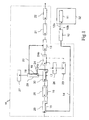
- an engine exhaust gas treatment system 10 has a urea solution supply tank 11 which supplies a urea supply module 12 which in turn supplies a urea injector 13 via line sections 14 to 20.
- Injector 13 injects the urea into a Selective Catalytic Reduction (SCR) catalytic converter 21 which is located in the exhaust system 22 of the engine 23.
- the engine has a turbo-charger 24 which has an input section 24a through which the air drawn through air filter 25 enters the engine via an air cooler 26.
- the exhaust gases leaving the engine 23 pass through the exit stage 24b of the turbo-charger in a conventional manner and then flow past the injector 13 and through the catalytic converter 21 on their way to the exit of the exhaust system 22.
- the vehicle is also provided with an air compressor 27 to power various pneumatic functions on the vehicle such as air brakes and an air suspension system for the cab.
- This air compressor is fed with air via a duct 28 which receives air via the air filter 25.
- the air which is drawn into the turbo-charger intake stage 24a passes through duct 29 before passing through air filter 25 and the further duct 30 after passing through the air filter.
- the urea passes from the supply module 12 to the injector 13 via line sections 15, 17 and 19 at which locations the urea flowing through the sections 15, 17, and 19 is exposed to the air flowing through air ducts 29, 30 and 28 respectively.
- FIG. 5 shows details of a heat exchanger arrangement which can be used in connection with the air duct 28 which supplies air to the compressor 27.
- a heat exchange core is provided by a pipe 31 which forms the section 19 of the supply line and which exposes the urea to the cooling effect of the air which is being drawn into the air compressor 27 via the duct 28.
- a pipe through which the urea flows can be arranged to extend within air ducts 29 and 30 in order to be exposed to the air flowing through air ducts 29 and 30 respectively.
- the urea is cooled in ducts 29, 30 and 28 it may, for example, only be cooled in duct 29 or 30, i.e. before or after passage through the air filter 25 and in machines which are not provided with an air compressor the further cooling in duct 28 will not occur. Conversely, if the cooling effect is adequate, the urea may only be cooled using the air which is to be drawn into the compressor via duct 28.
- the urea in tank 11 is further shielded from the effects of the sun and other influences by locating the urea tank 11 such that the fuel in the fuel tank 32 of the vehicle at the least partially insulates the urea from the heating effects of the sun and the heating effects of the exhaust of the engine.
- This tank arrangement also provides insulation from the heat coming from the cooling system of the engine as the cooling air may be directed downwardly after passing through the engine bay to an area where the fuel tank or tanks are often positioned.
- the urea tank 11 is completely surrounded by the fuel tank 32 to provide maximum heat insulation.
- the urea tank may not be surrounded by the fuel tank but simply immediately adjacent thereto (with the urea tank being divided from the fuel tank by a common wall for example) so that the urea tank is shielded from the direct heating effects of the sun and the heating effects of the exhaust of the engine and the cooling air of the engine as discussed above.
- the fuel tank 32 has a fuel filler spout 33 and the urea tank 11 has a urea filler spout 34.
- Fuel is drawn out of tank 32 via pipe 35 using a conventional electric fuel pump (not shown) and a fuel gauge 36 is also provided.
- a feed tube 37 is provided for the supply of urea to the module 12 from tank 11 via line 12a. The return of any surplus urea from the supply module 12 to the tank 11 is via line 12b.
- the fuel tank 32 is formed from a single plastic structure manufactured by a rotational moulding process. Such processes are known and will not be described in detail. However, reference is invited to web page http://en.wikipedia.org/wiki/Rotational_molding for further details.
- the fuel tank 32 is defmed by a closed volume 32a having an outside surface 32b, a bottom surface 32c and a top surface 32d.
- a concavity 11a is provided (also by the moulding process) which defines the volume for the urea tank 11.
- the concavity 11a includes near vertical walls 11b and a base 11c.
- the concavity 11a is closed by a cover 50 which is secured to the top surface 32d of the fuel tank 32 by ultrasonic welding ( Figure 4 ). Therefore, the cover 50 is sealed around its edge to prevent leakage.
- the fuel gauge 36 and feed tube 37 are inserted and secured in the cover 50.
- the cover 50 may be screwed to the tank 32.
- metal inserts may be provided in the tank 32 to receive the screws.
Abstract
Description
- The invention relates to treatment systems for treating exhaust gases from an internal combustion engine of a vehicle, particularly, but not exclusively so, a tractor.
- It is well known to provide a vehicle exhaust gas treatment system in which a urea solution is injected into a catalytic converter located in the exhaust system of an internal combustion engine, to significantly reduce the level of exhaust pollutants such as carbon monoxide, nitrogen oxide and particulate matter in the exhaust gases.
- Problems arise with such treatment systems since if the temperature of the urea exceeds 60°C, due to exposure to the sun or the close proximity of hot components on the vehicle, the urea starts to break down into corrosive constituents which can damage the components of the treatment system.
- It is an object of the present invention to provide an improved form of containment vessel for the urea solution used in the above treatment systems.
- Thus according to the present invention there is provided a multi-compartment vessel for fixing to a vehicle, the vessel being characterised by including a fuel tank form of moulded plastic, wherein a wall of the fuel tank comprises a concavity which defines the volume of a urea storage tank for storing urea, the vessel further comprising a closure element over the concavity.
- Advantageously, by forming the fuel tank of moulded plastic with a concavity in this way, the manufacturing and assembly process is simplified.
- The vessel may be formed by a rotational moulding process.
- By locating the urea tank relative to the fuel tank so that the fuel in the fuel tank at least partially insulates the urea from the heating effect of the sun and other heat sources (for example the heating effects of the exhaust of the engine and the cooling system of the engine)the temperature of the urea can be reduced.
- In a preferred construction the urea tank is completely surrounded by the fuel in the fuel tank to obtain the maximum insulating effect from the fuel.
- The present invention will now be described, by way of example only, with reference to the accompanying drawings in which:
-
Figure 1 shows diagrammatically a vehicle exhaust gas treatment system in accordance with the present invention; -
Figures 2 & 3 show perspective and part-sectional views through a combined fuel and urea tank in accordance with a second aspect of the present invention; -
Figure 4 shows an enlarged view of part Y shown inFigure 3 ; and, -
Figure 5 shows details of a heat exchanger associated with a compressor air supply duct. - Referring to the drawings, an engine exhaust
gas treatment system 10 has a ureasolution supply tank 11 which supplies aurea supply module 12 which in turn supplies aurea injector 13 vialine sections 14 to 20.Injector 13 injects the urea into a Selective Catalytic Reduction (SCR)catalytic converter 21 which is located in theexhaust system 22 of theengine 23. The engine has a turbo-charger 24 which has aninput section 24a through which the air drawn throughair filter 25 enters the engine via anair cooler 26. The exhaust gases leaving theengine 23 pass through theexit stage 24b of the turbo-charger in a conventional manner and then flow past theinjector 13 and through thecatalytic converter 21 on their way to the exit of theexhaust system 22. - The vehicle is also provided with an
air compressor 27 to power various pneumatic functions on the vehicle such as air brakes and an air suspension system for the cab. This air compressor is fed with air via aduct 28 which receives air via theair filter 25. - The air which is drawn into the turbo-
charger intake stage 24a passes throughduct 29 before passing throughair filter 25 and thefurther duct 30 after passing through the air filter. - In accordance with the present invention, the urea passes from the
supply module 12 to theinjector 13 vialine sections sections air ducts -
Figure 5 shows details of a heat exchanger arrangement which can be used in connection with theair duct 28 which supplies air to thecompressor 27. In this arrangement a heat exchange core is provided by apipe 31 which forms thesection 19 of the supply line and which exposes the urea to the cooling effect of the air which is being drawn into theair compressor 27 via theduct 28. - Similarly in
sections air ducts air ducts - As will be appreciated since the air which is drawn into the engine normally has a maximum temperature of 45°C this should maintain the temperature of the urea well below the critical 60°C temperature at which decomposition occurs.
- Although in the arrangement described above the urea is cooled in
ducts duct air filter 25 and in machines which are not provided with an air compressor the further cooling induct 28 will not occur. Conversely, if the cooling effect is adequate, the urea may only be cooled using the air which is to be drawn into the compressor viaduct 28. - The urea in
tank 11 is further shielded from the effects of the sun and other influences by locating theurea tank 11 such that the fuel in thefuel tank 32 of the vehicle at the least partially insulates the urea from the heating effects of the sun and the heating effects of the exhaust of the engine. This tank arrangement also provides insulation from the heat coming from the cooling system of the engine as the cooling air may be directed downwardly after passing through the engine bay to an area where the fuel tank or tanks are often positioned. - In a preferred arrangement in accordance with the present invention, shown in
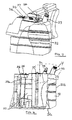
Figures 2 & 3 , theurea tank 11 is completely surrounded by thefuel tank 32 to provide maximum heat insulation. In certain tank configurations the urea tank may not be surrounded by the fuel tank but simply immediately adjacent thereto (with the urea tank being divided from the fuel tank by a common wall for example) so that the urea tank is shielded from the direct heating effects of the sun and the heating effects of the exhaust of the engine and the cooling air of the engine as discussed above. - In
Figures 2, 3 and4 , thefuel tank 32 has afuel filler spout 33 and the ureatank 11 has aurea filler spout 34. Fuel is drawn out oftank 32 viapipe 35 using a conventional electric fuel pump (not shown) and afuel gauge 36 is also provided. Afeed tube 37 is provided for the supply of urea to themodule 12 fromtank 11 vialine 12a. The return of any surplus urea from thesupply module 12 to thetank 11 is vialine 12b. - The
fuel tank 32 is formed from a single plastic structure manufactured by a rotational moulding process. Such processes are known and will not be described in detail. However, reference is invited to web page http://en.wikipedia.org/wiki/Rotational_molding for further details. - With reference to
Figures 3 and4 , thefuel tank 32 is defmed by a closedvolume 32a having anoutside surface 32b, a bottom surface 32c and a top surface 32d. Within the top surface 32d a concavity 11a is provided (also by the moulding process) which defines the volume for theurea tank 11. The concavity 11a includes near vertical walls 11b and a base 11c. - The concavity 11a is closed by a
cover 50 which is secured to the top surface 32d of thefuel tank 32 by ultrasonic welding (Figure 4 ). Therefore, thecover 50 is sealed around its edge to prevent leakage. Thefuel gauge 36 andfeed tube 37 are inserted and secured in thecover 50. - Alternatively, the
cover 50 may be screwed to thetank 32. In this case, metal inserts may be provided in thetank 32 to receive the screws. - From reading the present disclosure, other modification will be apparent to persons skilled in the art. Such modifications may involve other features which are already known in the field of vehicle exhaust treatment systems and component parts therefore and which may be used instead of or in addition to features already described herein.
Claims (7)
- A multi compartment vessel for fixing to a vehicle, the vessel being characterised by including a fuel tank (32) formed of moulded plastic, wherein a wall (11b,11c) of the fuel tank comprises a concavity (11 a) which defines the volume of a urea storage tank (11) for storing urea, the vessel further comprising a closure element (50) over the concavity.
- A vessel according to Claim 1 characterised in that the urea tank (11) is completely surrounded by fuel in the fuel tank (32) to obtain the maximum insulating effect from the fuel.
- A vessel according to Claim 1 or 2, characterised in that the vessel is formed by a rotational moulding process.
- A vessel according to anyone of Claims 1 to 3 characterised in that the closure element (50) is ultrasonically welded over the concavity.
- A vessel according to anyone of claims 1 to 3 characterised in that the closure element (5) is screwed over the concavity using metal inserts in the vessel which receive the screws.
- A vessel according to any one of claims 1 to 5 characterised in that a urea filter spout (34) and/or a urea feed tube (37) are mounted on the closure element (50).
- A vehicle engine exhaust gas treatment system for use on a tractor in which urea is injected into a catalytic converter (12) located in an exhaust (22) of an engine (23) from the urea storage tank (11) of a vessel according to any one of claims 1 to 5.
Applications Claiming Priority (2)
| Application Number | Priority Date | Filing Date | Title |
|---|---|---|---|
| GBGB0807173.0A GB0807173D0 (en) | 2008-04-19 | 2008-04-19 | Exhaust gas treatment system |
| EP09733517A EP2268905B1 (en) | 2008-04-19 | 2009-01-22 | Vehicle exhaust treatment systems |
Related Parent Applications (1)
| Application Number | Title | Priority Date | Filing Date |
|---|---|---|---|
| EP09733517.8 Division | 2009-01-22 |
Publications (2)
| Publication Number | Publication Date |
|---|---|
| EP2426332A1 true EP2426332A1 (en) | 2012-03-07 |
| EP2426332B1 EP2426332B1 (en) | 2013-06-19 |
Family
ID=39472403
Family Applications (2)
| Application Number | Title | Priority Date | Filing Date |
|---|---|---|---|
| EP11186821.2A Active EP2426332B1 (en) | 2008-04-19 | 2009-01-22 | Fuel tank comprising an urea tank |
| EP09733517A Active EP2268905B1 (en) | 2008-04-19 | 2009-01-22 | Vehicle exhaust treatment systems |
Family Applications After (1)
| Application Number | Title | Priority Date | Filing Date |
|---|---|---|---|
| EP09733517A Active EP2268905B1 (en) | 2008-04-19 | 2009-01-22 | Vehicle exhaust treatment systems |
Country Status (5)
| Country | Link |
|---|---|
| US (1) | US8429905B2 (en) |
| EP (2) | EP2426332B1 (en) |
| AT (1) | ATE555284T1 (en) |
| GB (1) | GB0807173D0 (en) |
| WO (1) | WO2009127278A1 (en) |
Cited By (1)
| Publication number | Priority date | Publication date | Assignee | Title |
|---|---|---|---|---|
| CN106285859A (en) * | 2015-06-27 | 2017-01-04 | 曼卡车和巴士股份公司 | With the reducing agent tank for guiding the integrated fluid passage adding hot fluid |
Families Citing this family (16)
| Publication number | Priority date | Publication date | Assignee | Title |
|---|---|---|---|---|
| DE102009000094A1 (en) * | 2009-01-09 | 2010-07-15 | Robert Bosch Gmbh | Tank for receiving an aqueous solution |
| CN101975128B (en) * | 2010-11-17 | 2013-10-16 | 中国第一汽车集团公司 | Pressureproof combined type fuel tank of column plastic pipe |
| CN102003314B (en) * | 2010-11-17 | 2013-10-30 | 中国第一汽车集团公司 | Three-post plastic-pipe pressure-resistance combined oil tank |
| CN101979257B (en) * | 2010-11-17 | 2013-12-25 | 中国第一汽车集团公司 | Pressure-resistant combined fuel tank with two-column plastic pipe |
| CN101973206B (en) * | 2010-11-17 | 2014-01-01 | 中国第一汽车集团公司 | Pressure proof combined type oil tank of multi-column plastic pipe |
| US8534686B1 (en) | 2010-12-30 | 2013-09-17 | Agco Corporation | Independent strut suspension |
| DE102011011631B4 (en) * | 2011-02-17 | 2014-10-16 | Continental Automotive Gmbh | Tank device for storing a liquid pollutant-reducing medium |
| US20130014496A1 (en) * | 2011-07-15 | 2013-01-17 | Caterpillar Inc. | Cooling system for engine aftertreatment system |
| DE102012103696A1 (en) | 2012-04-26 | 2013-10-31 | Cummins Ltd. | Exhaust gas treatment device used in e.g. passenger car, has spacer that is provided to maintain distance between flexible HWL tube and sleeve cladding, and air within sleeve cladding is conveyed to dosing unit using blower |
| DE102012112666B3 (en) * | 2012-12-19 | 2014-03-27 | Elkamet Kunststofftechnik Gmbh | Covering structure for resource container system for vehicle e.g. truck, has filler neck portion that is designed as terminal portion for resource spacer and is provided in apertures extending along cover housing wall |
| US9103600B2 (en) | 2012-12-21 | 2015-08-11 | Caterpillar Inc. | Injector cooling apparatus and method |
| WO2015045113A1 (en) * | 2013-09-27 | 2015-04-02 | 株式会社小松製作所 | Reducing agent tank and work vehicle |
| JP6218674B2 (en) * | 2014-05-28 | 2017-10-25 | 株式会社クボタ | Work vehicle |
| JP2016065542A (en) * | 2015-12-11 | 2016-04-28 | ヤンマー株式会社 | Work vehicle |
| JP6280536B2 (en) * | 2015-12-11 | 2018-02-14 | ヤンマー株式会社 | Tractor |
| JP6216413B2 (en) * | 2016-06-16 | 2017-10-18 | ヤンマー株式会社 | Tractor |
Citations (3)
| Publication number | Priority date | Publication date | Assignee | Title |
|---|---|---|---|---|
| US6223526B1 (en) * | 1998-06-17 | 2001-05-01 | Siemens Aktiengesellschaft | Dual compartment fuel storage tank |
| DE202006013535U1 (en) * | 2006-09-04 | 2006-11-09 | GEDIA Gebrüder Dingerkus GmbH | Fuel tank in particular of lorry, comprises integrated module for fine dust reduction solution |
| EP1736350A2 (en) * | 2005-06-24 | 2006-12-27 | MAN Nutzfahrzeuge Aktiengesellschaft | Vehicle with a reducing agent reservoir for an exhaust gas cleaning device |
Family Cites Families (4)
| Publication number | Priority date | Publication date | Assignee | Title |
|---|---|---|---|---|
| US5976475A (en) * | 1997-04-02 | 1999-11-02 | Clean Diesel Technologies, Inc. | Reducing NOx emissions from an engine by temperature-controlled urea injection for selective catalytic reduction |
| DE10324482B4 (en) * | 2003-05-30 | 2014-08-21 | Robert Bosch Gmbh | Device for metering a reducing agent to the exhaust gas of an internal combustion engine |
| DE10335265B4 (en) * | 2003-08-01 | 2014-02-27 | Man Truck & Bus Ag | Motor vehicle with special arrangement of a fuel tank, pre-silencer and reducing agent tanks |
| US20090188923A1 (en) * | 2007-12-10 | 2009-07-30 | Fuel Systems, Inc. | Urea solution tank assembly |
-
2008
- 2008-04-19 GB GBGB0807173.0A patent/GB0807173D0/en not_active Ceased
-
2009
- 2009-01-22 EP EP11186821.2A patent/EP2426332B1/en active Active
- 2009-01-22 US US12/988,385 patent/US8429905B2/en active Active
- 2009-01-22 WO PCT/EP2009/000363 patent/WO2009127278A1/en active Application Filing
- 2009-01-22 EP EP09733517A patent/EP2268905B1/en active Active
- 2009-01-22 AT AT09733517T patent/ATE555284T1/en active
Patent Citations (3)
| Publication number | Priority date | Publication date | Assignee | Title |
|---|---|---|---|---|
| US6223526B1 (en) * | 1998-06-17 | 2001-05-01 | Siemens Aktiengesellschaft | Dual compartment fuel storage tank |
| EP1736350A2 (en) * | 2005-06-24 | 2006-12-27 | MAN Nutzfahrzeuge Aktiengesellschaft | Vehicle with a reducing agent reservoir for an exhaust gas cleaning device |
| DE202006013535U1 (en) * | 2006-09-04 | 2006-11-09 | GEDIA Gebrüder Dingerkus GmbH | Fuel tank in particular of lorry, comprises integrated module for fine dust reduction solution |
Cited By (1)
| Publication number | Priority date | Publication date | Assignee | Title |
|---|---|---|---|---|
| CN106285859A (en) * | 2015-06-27 | 2017-01-04 | 曼卡车和巴士股份公司 | With the reducing agent tank for guiding the integrated fluid passage adding hot fluid |
Also Published As
| Publication number | Publication date |
|---|---|
| EP2268905B1 (en) | 2012-04-25 |
| ATE555284T1 (en) | 2012-05-15 |
| GB0807173D0 (en) | 2008-05-21 |
| US8429905B2 (en) | 2013-04-30 |
| EP2426332B1 (en) | 2013-06-19 |
| US20110036079A1 (en) | 2011-02-17 |
| WO2009127278A1 (en) | 2009-10-22 |
| EP2268905A1 (en) | 2011-01-05 |
Similar Documents
| Publication | Publication Date | Title |
|---|---|---|
| EP2426332B1 (en) | Fuel tank comprising an urea tank | |
| CN102016249B (en) | Railway vehicle with exhaust gas cleaning | |
| US8850797B2 (en) | Engine exhaust gas additive storage system | |
| US20130026765A1 (en) | Thermal shield for system for generating electric power | |
| US20090127265A1 (en) | Liquid receptacle for a vehicle | |
| US9598994B2 (en) | Cooling device for connection piece | |
| US20090038296A1 (en) | Liquid tank, breather device, and exhaust gas purification device for engine | |
| US20070196243A1 (en) | Reducing agent container having an improved structure | |
| JP2009508053A (en) | Vehicle tank for liquid reducing agent, especially urea solvent | |
| JP2009062841A (en) | Liquid storage structure for vehicle and exhaust emission control device | |
| US9222386B2 (en) | Injection device for metering a liquid additive, method for freezing an injection device and motor vehicle | |
| US20060201454A1 (en) | Heat storage tank | |
| KR101419447B1 (en) | Method for supplying an engine with exhaust gas, exhaust element, exhaust line and vehicle comprising means for supplying such an engine with exhaust gas | |
| US20190376436A1 (en) | Systems and methods for an exhaust-gas aftertreatment device | |
| US11225891B1 (en) | Durable high performance water-cooled exhaust systems and components | |
| RU2669126C2 (en) | Agricultural vehicle, storage device and method for producing the storage device | |
| JP4363176B2 (en) | Engine exhaust gas recirculation system | |
| US9650932B2 (en) | Insulated reductant tank | |
| AU2022256141A1 (en) | Heat exchanger with coolant manifold | |
| WO2019158993A1 (en) | Reserve tank | |
| JP2003278544A (en) | Air bleeding structure for vehicular water cooling system | |
| CN104040128A (en) | Device for exhaust treatment having a dosing unit for an exhaust treatment agent | |
| US11181025B2 (en) | SCR dosing unit for conveying and providing a liquid exhaust gas purification additive | |
| US20150167527A1 (en) | Systems and methods for cooling a diesel exhaust fluid dosing module of an agricultural vehicle | |
| JP2001254648A (en) | Exhaust gas recirculation system of internal combustion engine |
Legal Events
| Date | Code | Title | Description |
|---|---|---|---|
| AC | Divisional application: reference to earlier application |
Ref document number: 2268905 Country of ref document: EP Kind code of ref document: P |
|
| AK | Designated contracting states |
Kind code of ref document: A1 Designated state(s): AT BE BG CH CY CZ DE DK EE ES FI FR GB GR HR HU IE IS IT LI LT LU LV MC MK MT NL NO PL PT RO SE SI SK TR |
|
| PUAI | Public reference made under article 153(3) epc to a published international application that has entered the european phase |
Free format text: ORIGINAL CODE: 0009012 |
|
| 17P | Request for examination filed |
Effective date: 20120907 |
|
| RIN1 | Information on inventor provided before grant (corrected) |
Inventor name: MARINER, GERHARD Inventor name: FREI, PAUL Inventor name: FREYTAG, ERICH Inventor name: NAGELE, GUIDO |
|
| RIN1 | Information on inventor provided before grant (corrected) |
Inventor name: FREI, PAUL Inventor name: NAGELE, GUIDO Inventor name: THE OTHER INVENTORS HAVE AGREED TO WAIVE THEIR ENT Inventor name: MARINER, GERHARD |
|
| RIN1 | Information on inventor provided before grant (corrected) |
Inventor name: NAGELE, GUIDO Inventor name: FREYTAG, ERICH Inventor name: MARINER, GERHARD Inventor name: FREI, PAUL |
|
| GRAP | Despatch of communication of intention to grant a patent |
Free format text: ORIGINAL CODE: EPIDOSNIGR1 |
|
| GRAS | Grant fee paid |
Free format text: ORIGINAL CODE: EPIDOSNIGR3 |
|
| GRAA | (expected) grant |
Free format text: ORIGINAL CODE: 0009210 |
|
| AC | Divisional application: reference to earlier application |
Ref document number: 2268905 Country of ref document: EP Kind code of ref document: P |
|
| AK | Designated contracting states |
Kind code of ref document: B1 Designated state(s): AT BE BG CH CY CZ DE DK EE ES FI FR GB GR HR HU IE IS IT LI LT LU LV MC MK MT NL NO PL PT RO SE SI SK TR |
|
| REG | Reference to a national code |
Ref country code: GB Ref legal event code: FG4D |
|
| REG | Reference to a national code |
Ref country code: CH Ref legal event code: EP |
|
| REG | Reference to a national code |
Ref country code: AT Ref legal event code: REF Ref document number: 617783 Country of ref document: AT Kind code of ref document: T Effective date: 20130715 |
|
| REG | Reference to a national code |
Ref country code: IE Ref legal event code: FG4D |
|
| REG | Reference to a national code |
Ref country code: DE Ref legal event code: R096 Ref document number: 602009016635 Country of ref document: DE Effective date: 20130814 |
|
| PG25 | Lapsed in a contracting state [announced via postgrant information from national office to epo] |
Ref country code: ES Free format text: LAPSE BECAUSE OF FAILURE TO SUBMIT A TRANSLATION OF THE DESCRIPTION OR TO PAY THE FEE WITHIN THE PRESCRIBED TIME-LIMIT Effective date: 20130930 Ref country code: SE Free format text: LAPSE BECAUSE OF FAILURE TO SUBMIT A TRANSLATION OF THE DESCRIPTION OR TO PAY THE FEE WITHIN THE PRESCRIBED TIME-LIMIT Effective date: 20130619 Ref country code: LT Free format text: LAPSE BECAUSE OF FAILURE TO SUBMIT A TRANSLATION OF THE DESCRIPTION OR TO PAY THE FEE WITHIN THE PRESCRIBED TIME-LIMIT Effective date: 20130619 Ref country code: NO Free format text: LAPSE BECAUSE OF FAILURE TO SUBMIT A TRANSLATION OF THE DESCRIPTION OR TO PAY THE FEE WITHIN THE PRESCRIBED TIME-LIMIT Effective date: 20130919 Ref country code: SI Free format text: LAPSE BECAUSE OF FAILURE TO SUBMIT A TRANSLATION OF THE DESCRIPTION OR TO PAY THE FEE WITHIN THE PRESCRIBED TIME-LIMIT Effective date: 20130619 Ref country code: FI Free format text: LAPSE BECAUSE OF FAILURE TO SUBMIT A TRANSLATION OF THE DESCRIPTION OR TO PAY THE FEE WITHIN THE PRESCRIBED TIME-LIMIT Effective date: 20130619 Ref country code: GR Free format text: LAPSE BECAUSE OF FAILURE TO SUBMIT A TRANSLATION OF THE DESCRIPTION OR TO PAY THE FEE WITHIN THE PRESCRIBED TIME-LIMIT Effective date: 20130920 |
|
| REG | Reference to a national code |
Ref country code: AT Ref legal event code: MK05 Ref document number: 617783 Country of ref document: AT Kind code of ref document: T Effective date: 20130619 |
|
| REG | Reference to a national code |
Ref country code: LT Ref legal event code: MG4D |
|
| PG25 | Lapsed in a contracting state [announced via postgrant information from national office to epo] |
Ref country code: HR Free format text: LAPSE BECAUSE OF FAILURE TO SUBMIT A TRANSLATION OF THE DESCRIPTION OR TO PAY THE FEE WITHIN THE PRESCRIBED TIME-LIMIT Effective date: 20130619 Ref country code: BG Free format text: LAPSE BECAUSE OF FAILURE TO SUBMIT A TRANSLATION OF THE DESCRIPTION OR TO PAY THE FEE WITHIN THE PRESCRIBED TIME-LIMIT Effective date: 20130919 |
|
| REG | Reference to a national code |
Ref country code: NL Ref legal event code: VDEP Effective date: 20130619 |
|
| PG25 | Lapsed in a contracting state [announced via postgrant information from national office to epo] |
Ref country code: IT Free format text: LAPSE BECAUSE OF NON-PAYMENT OF DUE FEES Effective date: 20130122 Ref country code: LV Free format text: LAPSE BECAUSE OF FAILURE TO SUBMIT A TRANSLATION OF THE DESCRIPTION OR TO PAY THE FEE WITHIN THE PRESCRIBED TIME-LIMIT Effective date: 20130619 |
|
| PG25 | Lapsed in a contracting state [announced via postgrant information from national office to epo] |
Ref country code: EE Free format text: LAPSE BECAUSE OF FAILURE TO SUBMIT A TRANSLATION OF THE DESCRIPTION OR TO PAY THE FEE WITHIN THE PRESCRIBED TIME-LIMIT Effective date: 20130619 Ref country code: SK Free format text: LAPSE BECAUSE OF FAILURE TO SUBMIT A TRANSLATION OF THE DESCRIPTION OR TO PAY THE FEE WITHIN THE PRESCRIBED TIME-LIMIT Effective date: 20130619 Ref country code: BE Free format text: LAPSE BECAUSE OF FAILURE TO SUBMIT A TRANSLATION OF THE DESCRIPTION OR TO PAY THE FEE WITHIN THE PRESCRIBED TIME-LIMIT Effective date: 20130619 Ref country code: CY Free format text: LAPSE BECAUSE OF FAILURE TO SUBMIT A TRANSLATION OF THE DESCRIPTION OR TO PAY THE FEE WITHIN THE PRESCRIBED TIME-LIMIT Effective date: 20130814 Ref country code: PT Free format text: LAPSE BECAUSE OF FAILURE TO SUBMIT A TRANSLATION OF THE DESCRIPTION OR TO PAY THE FEE WITHIN THE PRESCRIBED TIME-LIMIT Effective date: 20131021 Ref country code: AT Free format text: LAPSE BECAUSE OF FAILURE TO SUBMIT A TRANSLATION OF THE DESCRIPTION OR TO PAY THE FEE WITHIN THE PRESCRIBED TIME-LIMIT Effective date: 20130619 Ref country code: IS Free format text: LAPSE BECAUSE OF FAILURE TO SUBMIT A TRANSLATION OF THE DESCRIPTION OR TO PAY THE FEE WITHIN THE PRESCRIBED TIME-LIMIT Effective date: 20131019 Ref country code: CZ Free format text: LAPSE BECAUSE OF FAILURE TO SUBMIT A TRANSLATION OF THE DESCRIPTION OR TO PAY THE FEE WITHIN THE PRESCRIBED TIME-LIMIT Effective date: 20130619 |
|
| PG25 | Lapsed in a contracting state [announced via postgrant information from national office to epo] |
Ref country code: NL Free format text: LAPSE BECAUSE OF FAILURE TO SUBMIT A TRANSLATION OF THE DESCRIPTION OR TO PAY THE FEE WITHIN THE PRESCRIBED TIME-LIMIT Effective date: 20130619 Ref country code: RO Free format text: LAPSE BECAUSE OF FAILURE TO SUBMIT A TRANSLATION OF THE DESCRIPTION OR TO PAY THE FEE WITHIN THE PRESCRIBED TIME-LIMIT Effective date: 20130619 Ref country code: PL Free format text: LAPSE BECAUSE OF FAILURE TO SUBMIT A TRANSLATION OF THE DESCRIPTION OR TO PAY THE FEE WITHIN THE PRESCRIBED TIME-LIMIT Effective date: 20130619 |
|
| PG25 | Lapsed in a contracting state [announced via postgrant information from national office to epo] |
Ref country code: CY Free format text: LAPSE BECAUSE OF FAILURE TO SUBMIT A TRANSLATION OF THE DESCRIPTION OR TO PAY THE FEE WITHIN THE PRESCRIBED TIME-LIMIT Effective date: 20130619 |
|
| PLBE | No opposition filed within time limit |
Free format text: ORIGINAL CODE: 0009261 |
|
| STAA | Information on the status of an ep patent application or granted ep patent |
Free format text: STATUS: NO OPPOSITION FILED WITHIN TIME LIMIT |
|
| PG25 | Lapsed in a contracting state [announced via postgrant information from national office to epo] |
Ref country code: DK Free format text: LAPSE BECAUSE OF FAILURE TO SUBMIT A TRANSLATION OF THE DESCRIPTION OR TO PAY THE FEE WITHIN THE PRESCRIBED TIME-LIMIT Effective date: 20130619 |
|
| 26N | No opposition filed |
Effective date: 20140320 |
|
| REG | Reference to a national code |
Ref country code: DE Ref legal event code: R097 Ref document number: 602009016635 Country of ref document: DE Effective date: 20140320 |
|
| PG25 | Lapsed in a contracting state [announced via postgrant information from national office to epo] |
Ref country code: LU Free format text: LAPSE BECAUSE OF FAILURE TO SUBMIT A TRANSLATION OF THE DESCRIPTION OR TO PAY THE FEE WITHIN THE PRESCRIBED TIME-LIMIT Effective date: 20140122 |
|
| REG | Reference to a national code |
Ref country code: CH Ref legal event code: PL |
|
| PG25 | Lapsed in a contracting state [announced via postgrant information from national office to epo] |
Ref country code: CH Free format text: LAPSE BECAUSE OF NON-PAYMENT OF DUE FEES Effective date: 20140131 Ref country code: LI Free format text: LAPSE BECAUSE OF NON-PAYMENT OF DUE FEES Effective date: 20140131 |
|
| REG | Reference to a national code |
Ref country code: IE Ref legal event code: MM4A |
|
| PG25 | Lapsed in a contracting state [announced via postgrant information from national office to epo] |
Ref country code: IE Free format text: LAPSE BECAUSE OF NON-PAYMENT OF DUE FEES Effective date: 20140122 |
|
| PG25 | Lapsed in a contracting state [announced via postgrant information from national office to epo] |
Ref country code: MC Free format text: LAPSE BECAUSE OF FAILURE TO SUBMIT A TRANSLATION OF THE DESCRIPTION OR TO PAY THE FEE WITHIN THE PRESCRIBED TIME-LIMIT Effective date: 20130619 |
|
| REG | Reference to a national code |
Ref country code: FR Ref legal event code: PLFP Year of fee payment: 8 |
|
| PG25 | Lapsed in a contracting state [announced via postgrant information from national office to epo] |
Ref country code: MT Free format text: LAPSE BECAUSE OF FAILURE TO SUBMIT A TRANSLATION OF THE DESCRIPTION OR TO PAY THE FEE WITHIN THE PRESCRIBED TIME-LIMIT Effective date: 20130619 |
|
| PG25 | Lapsed in a contracting state [announced via postgrant information from national office to epo] |
Ref country code: HU Free format text: LAPSE BECAUSE OF FAILURE TO SUBMIT A TRANSLATION OF THE DESCRIPTION OR TO PAY THE FEE WITHIN THE PRESCRIBED TIME-LIMIT; INVALID AB INITIO Effective date: 20090122 Ref country code: TR Free format text: LAPSE BECAUSE OF FAILURE TO SUBMIT A TRANSLATION OF THE DESCRIPTION OR TO PAY THE FEE WITHIN THE PRESCRIBED TIME-LIMIT Effective date: 20130619 |
|
| REG | Reference to a national code |
Ref country code: FR Ref legal event code: PLFP Year of fee payment: 9 |
|
| REG | Reference to a national code |
Ref country code: FR Ref legal event code: PLFP Year of fee payment: 10 |
|
| PGFP | Annual fee paid to national office [announced via postgrant information from national office to epo] |
Ref country code: GB Payment date: 20180119 Year of fee payment: 10 |
|
| PGFP | Annual fee paid to national office [announced via postgrant information from national office to epo] |
Ref country code: IT Payment date: 20180129 Year of fee payment: 10 |
|
| PG25 | Lapsed in a contracting state [announced via postgrant information from national office to epo] |
Ref country code: MK Free format text: LAPSE BECAUSE OF FAILURE TO SUBMIT A TRANSLATION OF THE DESCRIPTION OR TO PAY THE FEE WITHIN THE PRESCRIBED TIME-LIMIT Effective date: 20130619 |
|
| GBPC | Gb: european patent ceased through non-payment of renewal fee |
Effective date: 20190122 |
|
| PG25 | Lapsed in a contracting state [announced via postgrant information from national office to epo] |
Ref country code: GB Free format text: LAPSE BECAUSE OF NON-PAYMENT OF DUE FEES Effective date: 20190122 |
|
| PG25 | Lapsed in a contracting state [announced via postgrant information from national office to epo] |
Ref country code: IT Free format text: LAPSE BECAUSE OF NON-PAYMENT OF DUE FEES Effective date: 20190122 |
|
| REG | Reference to a national code |
Ref country code: DE Ref legal event code: R084 Ref document number: 602009016635 Country of ref document: DE |
|
| PGFP | Annual fee paid to national office [announced via postgrant information from national office to epo] |
Ref country code: FR Payment date: 20230124 Year of fee payment: 15 |
|
| PGFP | Annual fee paid to national office [announced via postgrant information from national office to epo] |
Ref country code: DE Payment date: 20230123 Year of fee payment: 15 |
|
| P01 | Opt-out of the competence of the unified patent court (upc) registered |
Effective date: 20230518 |