EP2426247A1 - Washing machine - Google Patents
Washing machine Download PDFInfo
- Publication number
- EP2426247A1 EP2426247A1 EP10175008A EP10175008A EP2426247A1 EP 2426247 A1 EP2426247 A1 EP 2426247A1 EP 10175008 A EP10175008 A EP 10175008A EP 10175008 A EP10175008 A EP 10175008A EP 2426247 A1 EP2426247 A1 EP 2426247A1
- Authority
- EP
- European Patent Office
- Prior art keywords
- sump
- washing machine
- filter
- magnetic
- filter element
- Prior art date
- Legal status (The legal status is an assumption and is not a legal conclusion. Google has not performed a legal analysis and makes no representation as to the accuracy of the status listed.)
- Withdrawn
Links
- 238000005406 washing Methods 0.000 title claims abstract description 62
- 230000005291 magnetic effect Effects 0.000 claims abstract description 104
- 235000014676 Phragmites communis Nutrition 0.000 claims description 4
- 230000005294 ferromagnetic effect Effects 0.000 claims description 4
- 239000002902 ferrimagnetic material Substances 0.000 claims description 2
- 239000003302 ferromagnetic material Substances 0.000 claims description 2
- 230000000007 visual effect Effects 0.000 claims description 2
- 230000003993 interaction Effects 0.000 description 5
- XLYOFNOQVPJJNP-UHFFFAOYSA-N water Substances O XLYOFNOQVPJJNP-UHFFFAOYSA-N 0.000 description 4
- 238000004519 manufacturing process Methods 0.000 description 3
- 239000000463 material Substances 0.000 description 3
- 238000000465 moulding Methods 0.000 description 3
- XEEYBQQBJWHFJM-UHFFFAOYSA-N Iron Chemical compound [Fe] XEEYBQQBJWHFJM-UHFFFAOYSA-N 0.000 description 2
- 238000004140 cleaning Methods 0.000 description 2
- 239000003599 detergent Substances 0.000 description 2
- 238000011144 upstream manufacturing Methods 0.000 description 2
- 239000000853 adhesive Substances 0.000 description 1
- 230000001070 adhesive effect Effects 0.000 description 1
- 229910000828 alnico Inorganic materials 0.000 description 1
- 230000001419 dependent effect Effects 0.000 description 1
- 238000001514 detection method Methods 0.000 description 1
- 238000001035 drying Methods 0.000 description 1
- 230000007613 environmental effect Effects 0.000 description 1
- 230000005293 ferrimagnetic effect Effects 0.000 description 1
- 229910052742 iron Inorganic materials 0.000 description 1
- 238000012423 maintenance Methods 0.000 description 1
- 239000002184 metal Substances 0.000 description 1
- 229910052751 metal Inorganic materials 0.000 description 1
- 229910001172 neodymium magnet Inorganic materials 0.000 description 1
- 229910000859 α-Fe Inorganic materials 0.000 description 1
Images


Classifications
-
- D—TEXTILES; PAPER
- D06—TREATMENT OF TEXTILES OR THE LIKE; LAUNDERING; FLEXIBLE MATERIALS NOT OTHERWISE PROVIDED FOR
- D06F—LAUNDERING, DRYING, IRONING, PRESSING OR FOLDING TEXTILE ARTICLES
- D06F39/00—Details of washing machines not specific to a single type of machines covered by groups D06F9/00 - D06F27/00
- D06F39/10—Filtering arrangements
-
- D—TEXTILES; PAPER
- D06—TREATMENT OF TEXTILES OR THE LIKE; LAUNDERING; FLEXIBLE MATERIALS NOT OTHERWISE PROVIDED FOR
- D06F—LAUNDERING, DRYING, IRONING, PRESSING OR FOLDING TEXTILE ARTICLES
- D06F2103/00—Parameters monitored or detected for the control of domestic laundry washing machines, washer-dryers or laundry dryers
- D06F2103/42—Parameters monitored or detected for the control of domestic laundry washing machines, washer-dryers or laundry dryers related to filters or pumps
Definitions
- the invention relates to a washing machine (this expression including also a washing machine having dryer function) comprising a filter element.
- GB 1,197,919 B discloses a washing machine, wherein a filter element is provided below a tub of the washing machine.
- the filter element is removable through an opening in the drum of the washing machine, which is closed by a plug.
- DE 10 2006 043 516 B3 discloses a washing machine comprising a fluff filter accessible through a front of a housing of the washing machine.
- the washing machine further comprises a detection system for determining a correct position of the filter element, which comprises a magnetic sensor.
- the washing machine performs a safety function if the filter is not correctly positioned.
- US 7,020,986 B1 discloses a washing and drying machine which comprises a drawer-type lint trap device accessible from the front surface of the machine.
- the machine comprises a detecting unit comprising a magnetic sensor for detecting the position of the lint trap device.
- a washing machine comprises a tub having a sump and a draining circuit, wherein the sump is fluidly connected to the draining circuit.
- a filter element is provided, which is removably positionable in the sump. I.e. the filter element can be removed from the sump by a user, e.g. for cleaning thereof, and can be reinserted into the sump thereafter.
- the filter element As the filter element is positioned in the sump, upstream the draining circuit, foreign objects and fluff are filtered effectively out of the water drained from the tub, i.e. foreign objects or fluff do not enter the draining circuit of the washing machine.
- foreign objects and fluff do not enter the draining circuit of the washing machine.
- the filter element comprises at least one first magnetic element which is adapted to magnetically interact or cooperate with at least one second magnetic element arranged at the sump.
- the interaction between the magnetic elements provides a self-alignment and positioning of the filter element to and at the correct position or operating position. That means even when a user places the filter in the sump in an incorrect or misaligned position, the magnetic interaction, in particular attraction, between the at least one first and the at least one second magnetic element moves the filter element into the correct position, i.e. into its operating position.
- the operating position of the filter element is secured by attraction force between the at least one first and the at least one second magnetic element.
- the washing machine provides a convenient handling and positioning of the filter element within the sump, in particular a user can be certain that the filter element positions itself in its correct position, e.g. such that fluff bypassing the filter or filter drum collisions due to an incorrect position of the filter element are avoided. Furthermore, due to the presence of the first and/or the second magnetic element, metallic foreign objects, e.g. coins, are trapped securely in the filter element.
- the at least one second magnetic element is arranged on an inner surface of the sump, or on an outer surface of the sump, and can additionally or alternatively be embedded, totally or partially, in the sump.
- the magnetic element is attached subsequent to fabrication of the sump to an inner or outer surface of the sump, such that a replacement of the magnetic element can be easily achieved.
- Another example would be to embed, totally or partially, the magnetic element within the sump, e.g. during molding the sump.
- the magnetic element is at least partially encapsulated and thereby protected by the material of the sump.
- the magnetic element is attached subsequent to fabrication of the filter element to an inner or outer surface of the filter element, such that a replacement of the magnetic element can be easily achieved.
- the magnetic element is embedded, totally or partially, within the filter element, e.g. during molding the filter element.
- the magnetic element is at least partially encapsulated and thereby protected by the material of the filter element.
- the tub and the sump are integrally formed. Thereby no additional attaching or assembling step for mounting the sump at the tub is required, whereby the assembly of the washing machine is facilitated and the assembly time reduced.
- a chamber for at least a portion of a draining pump of the washing machine is integrally formed with the tub and the sump, such that less assembly steps and assembly time are required during assembly of the washing machine.
- the at least one second magnetic element is integrated in, associated to and additionally, or alternatively, connected to a sensor element or a magnetic circuit comprising a sensor element for determining a position or the positioning in the correct position of the filter element.
- the sensor element or magnetic circuit provides the additional function of verifying the filter element being in its operating position.
- a sensor element is adapted to sense whether the first or second magnetic element is in its correct position, e.g. whether the magnetic elements face or contact each other, and to determine thereby whether the filter element is in its correct position.
- the sensor element is connected to a logic unit of the washing machine for receiving a sensor signal.
- the logic unit enables an operation of the washing machine only if the filter element is correctly positioned in the sump as indicated by the sensor signal (preferably enables a washing operation). E.g. a washing operation is preferably prevented when the filter is not in its operating position.
- the sensor element or the magnetic circuit comprising a sensor element comprises a reed sensor or a hall sensor to detect the operating position of the filter element.
- Reed sensors and hall sensors are robust and not sensitive to environmental influences like water and heat. Thus a robust sensor element for conditions in a washing machine is provided.
- the sensor element or the magnetic circuit comprising the sensor element is connected to a visual interface, e.g. of the washing machine console, and additionally or alternatively to a speaker.
- the sensor element is connected, e.g. wireless or by wire, to the logic unit of the washing machine or is directly connected to an interface control having e.g. an audio source and/or indicator, such that an incorrect position of the filter element can be communicated/indicated to a user.
- an interface control having e.g. an audio source and/or indicator, such that an incorrect position of the filter element can be communicated/indicated to a user.
- the filter element is not within the sump the user is informed thereof and can take the appropriate steps, i.e. insert the filter element into the sump.
- the at least one first magnetic element and additionally or alternatively the at least one second magnetic element is a magnet, in particular a permanent magnet or an electromagnet.
- a magnet in particular a permanent magnet or an electromagnet.
- the second magnetic element can be an electromagnet which is only operated during inserting the filter element or which increases its magnetic force during inserting the filter element, i.e. the magnetic field force can be adapted to the present requirement.
- the first or the second magnetic element is a permanent magnet, which provides a low-maintenance possibility for achieving self-alignment and positioning, i.e. securing, of the filter element.
- the at least one first magnetic element or the at least one second magnetic element comprises ferromagnetic material, e.g. iron, AlNiCo, NdFeB, or ferrimagnetic material, like ferrite, adapted to cooperate with the above described corresponding magnet of the second or first magnetic element in that an attractive force is exerted between the at least one first and the at least one second magnetic element.
- ferromagnetic material e.g. iron, AlNiCo, NdFeB, or ferrimagnetic material, like ferrite
- the filter element and additionally or alternatively the sump comprises a locking or snap fitting element for fixing or locking the filter element in place within the sump. I.e. after the above described self-alignment and positioning of the filter element within the sump, the filter element is snapped or locked securely in the sump.
- This is particularly advantageous as the user does not have to check or verify himself whether the filter element is in the correct position to lock the filter element with the snap fitting element, but this position is provided by the self-alignment of the filter element, provided by the first and second magnetic elements.
- the attractive force between the first and second element(s) is strong enough that a self-locking is provided by the magnetic attraction, such that no additional locking or snap fitting element is required.
- the at least one first magnetic element contacts the at least one second magnetic element in the operating position of the filter element, such that a maximum interaction, i.e. attraction, between the magnetic elements is provided.
- the filter element comprises at least two magnetic elements adapted to cooperate with at least two magnetic elements arranged at the sump.
- the self-alignment of the filter element within the sump is further improved due to additional attraction force between the additional magnetic elements and the additional attraction points or locations.
- the at least two magnetic elements of the filter element and additionally or alternatively the at least two magnetic elements arranged at the sump have opposite polarity.
- the at least two magnetic elements of the filter element have opposite polarities, i.e. the side of the magnetic elements facing the sump comprise opposite polarities.
- the magnetic elements of the sump also comprise the corresponding opposite polarities to each other, but opposite to the polarity to the magnetic elements of the filter element.
- the filter element is positioned back to front as in such a position the like polarities or poles of the magnetic elements of the filter element and the sump would cause them to repel. I.e. a user would recognize the incorrect position of the filter element, because the filter element would not be attracted to the sump.
- the above described washing machine can be a front-loading type or a top-loading type washing machine. Further, the washing machine can also be a washing machine having a dryer function.
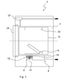
- Fig. 1 depicts a schematic cross-sectional side view of a washing machine 2 comprising a filter 16.
- a tub 4 of the washing machine 2 comprises a sump 6 which holds a filter 16, preferably a basket filter.
- the water intake from tap, and the draining outlet of the washing machine 2 are shown by arrows, i.e. water flows from an inlet through a detergent drawer 32 into the tub 4 and is pumped by a pump in the draining circuit 8 from the tub 4, through the filter 16 in the sump 6, to the outside of the machine.
- the drum 10 of the washing machine 2 advantageously comprises a conventional lifter 20 and a lifter 18 that can be opened or removed.
- the filter 16 is accessible for a user, preferably through a loading door 34 of the machine 2 (or in the case of a top loading machine through a suitable porthole present on the lateral surface of the washing drum), by opening a lid of the removable or openable lifter 18, which covers a corresponding opening of the drum 10 of the washing machine. Thereby a user can remove the filter 16 for cleaning or replacement through the opened lifter 18 and the corresponding opening of the drum 10 after opening the lifter 18.
- the above described lifter 18 which can be opened isn't provided, and the opening of the drum 10 which allows the access to the filter 16 is in this case closed by a specific lid, not illustrated, associated to the drum 10 in such a way that it can be moved or removed by a user in order to removing/repositioning the filter 16.
- a first magnetic element 12, for example a magnet is preferably arranged at the filter 16 and it is adapted to magnetically interact or cooperate with (in the case of a magnet it is adapted to attract) a second magnetic element 14, for example a ferromagnetic element, arranged at the sump 6 assisting in self-aligning the filter 16 into its operation position when (re)inserting the filter 16 into the sump 6.
- metallic i.e. made at least partially of a metal which may be attracted by a magnet
- foreign objects e.g. coins
- Fig. 2 shows a detail of a perspective front view of the sump 6 and the removed filter 16 of the washing machine 2 according to a first embodiment.
- the tub 4 is preferably integrally formed with the sump 6, which comprises a cavity to receive the filter 16 therein.
- the first magnetic element 12 e.g. a magnet
- the second magnetic element 14 e.g. a ferromagnetic element
- the filter 16 further comprises snap fits 22, 22', preferably placed on opposing sides thereof, to securely hold the filter 16 in place within the sump 6 after inserting the filter 16.
- first magnetic element 12 is associated to a bottom part of the filter 16, and the second magnetic element 14 is associated to a bottom 28 of the sump 6, the first magnetic element 12 may be associated substantially to any part of the filter 16 (for example to a lateral wall of the latter), and the second magnetic element may be associated substantially to any part of the sump 6 (for example to a lateral wall of the latter, in a position in which when the filter 16 is correctly inserted in the sump 6 the first and second magnetic elements face one another), provided that the reciprocal positioning of the first and second magnetic elements is such that the interaction between these magnetic elements provides a self-alignment and positioning of the filter 16 to and at the correct position or operating position.
- Fig. 3 shows a detail of a cross-sectional front view of Fig. 2 . It can be seen that the snap fits 22, 22' of the filter 16 are adapted to snap into correspondingly formed shoulders 30, 30' of the sump 6 arranged at the upper border of the sump cavity. Further, the bottom 28 of the sump 6 preferably comprises an inserting portion such that the second magnetic element 14 can be easily inserted in or attached to the sump 6 at the time of assembling the washing machine. Alternatively the second magnetic element 14 can be embedded into the sump 6. For example during fabrication of the sump 6 by placing the second magnetic element 14 in a cast for molding the sump 6, such that the second magnetic element 14 is at least partially or completely embedded or enclosed in the material of the sump 6. Alternatively the second magnetic element 14 can be attached to the sump 6 by fixing means like, for example, screws or by an adhesive.
- Fig. 4 depicts a detail of a perspective front view of the sump of Fig. 2 with inserted filter 16, i.e. the filter 16 is in its operating position.
- the filter 16 is preferably provided with a grip 24.
- Fig. 5 shows a detail of a cross-sectional front view of Fig. 4 .
- the first magnetic element 12 of the filter 16 directly contacts the second magnetic element 14 of the sump 6. Thereby a maximum interaction between the first magnetic element 12 and the second magnetic element 14 is achieved, such that the filter 16 is self-guided into the correct position even when initially the filter 16 is placed by a user in the sump 6 in an incorrect position.
- the filter 16 is positioned in the sump 6, i.e. upstream the draining circuit 8, fluff and foreign objects cannot enter the draining circuit 8.
- the draining circuit 8 is efficiently protected from foreign objects, e.g. the service life of a draining pump within the draining circuit 8 is increased.
- the snap fits 22, 22' are snapped in place or locked below the shoulder 30, 30' of the sump 6.
- the first magnetic element 12 and the second magnetic element 14, i.e. the attractive force therebetween are preferably adapted to snap the snap fits 22, 22' into their place below the shoulders 30, 30'.
- the snap fits 22, 22' are pushed by a user below the border 30, 30'.
- the filter 16 is self-aligned due to the attracting force between the first magnetic element 12 and second magnetic element 14 into an initial position within the sump 6 from where a user pushes the filter downwards into the sump 6, such that the snap fits 22, 22' are pushed below the shoulder 30, 30' and the filter 16 thereby securely locked. I.e. in this case the filter 16 is not self-aligned into its operating position, but into an initial position from where a user can push the filter 16 into its operating position within the sump 6.
- locking of the filter 16 in its operation position in the sump 6 is exclusively provided by the magnetic attraction between the one or more first magnetic elements and one or more second magnetic elements.
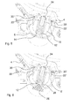
- Fig. 6 shows a detail of a cross-sectional front view of a sump 6' with inserted filter 16 according to a second embodiment.
- the second magnetic element for example a ferromagnetic or ferrimagnetic element, not shown
- the sensor 26 is attached to the sump 6' from the outside to provide enough space for the sensor 26.
- a sensor line is connecting the sensor to a logic unit (not shown) of the washing machine 2 for providing the sensor signal to the logic unit.
- a reed sensor or switch is actuated when the first magnetic element 12 is in contact with or is close to the sensor 26.
- the sensor 26 is actuated when the filter 16 is in its operating position.
- the actuated sensor 26 closes a circuit thereby generating a signal which is transmitted via the sensor line to the logic unit of the washing machine, whereby the user is informed, e.g. via a display, that the filter 16 is in its operating position.
- the activated sensor 26 opens a circuit.
- the logic unit is adapted to prevent an operation of the washing machine 2 when the filter 16 is not within the sump 6' (or not correctly positioned).
- the washing machine 2 is provided with a sensing and feedback system for detecting the filter 16 being in its operation position.
Landscapes
- Engineering & Computer Science (AREA)
- Textile Engineering (AREA)
- Detail Structures Of Washing Machines And Dryers (AREA)
- Main Body Construction Of Washing Machines And Laundry Dryers (AREA)
- Control Of Washing Machine And Dryer (AREA)
Abstract
The invention relates to a washing machine (2) comprising a tub (4) having a sump (6), a draining circuit (8), wherein the sump (6) is fluidly connected to the draining circuit (8), and a filter element (16), which is removably positionable in the sump (6), wherein the filter element (16) comprises at least one first magnetic element (12) adapted to magnetically cooperate with at least one second magnetic element (14) arranged at the sump (6), such that the filter element (16) is positioned in its operating position in the sump (6).
Description
- The invention relates to a washing machine (this expression including also a washing machine having dryer function) comprising a filter element.
-
GB 1,197,919 B -
DE 10 2006 043 516 B3 discloses a washing machine comprising a fluff filter accessible through a front of a housing of the washing machine. The washing machine further comprises a detection system for determining a correct position of the filter element, which comprises a magnetic sensor. The washing machine performs a safety function if the filter is not correctly positioned. -
US 7,020,986 B1 discloses a washing and drying machine which comprises a drawer-type lint trap device accessible from the front surface of the machine. The machine comprises a detecting unit comprising a magnetic sensor for detecting the position of the lint trap device. - It is an object of the invention to provide a washing machine providing easy handling and use of a filter element.
- The invention is defined in claim 1. Particular embodiments are set out in the dependent claims.
- According to claim 1, a washing machine comprises a tub having a sump and a draining circuit, wherein the sump is fluidly connected to the draining circuit. A filter element is provided, which is removably positionable in the sump. I.e. the filter element can be removed from the sump by a user, e.g. for cleaning thereof, and can be reinserted into the sump thereafter. As the filter element is positioned in the sump, upstream the draining circuit, foreign objects and fluff are filtered effectively out of the water drained from the tub, i.e. foreign objects or fluff do not enter the draining circuit of the washing machine. For correctly positioning the filter element within the sump, i.e. to achieve the operating position of the filter element, the filter element comprises at least one first magnetic element which is adapted to magnetically interact or cooperate with at least one second magnetic element arranged at the sump. The interaction between the magnetic elements provides a self-alignment and positioning of the filter element to and at the correct position or operating position. That means even when a user places the filter in the sump in an incorrect or misaligned position, the magnetic interaction, in particular attraction, between the at least one first and the at least one second magnetic element moves the filter element into the correct position, i.e. into its operating position. In particular the operating position of the filter element is secured by attraction force between the at least one first and the at least one second magnetic element. The washing machine provides a convenient handling and positioning of the filter element within the sump, in particular a user can be certain that the filter element positions itself in its correct position, e.g. such that fluff bypassing the filter or filter drum collisions due to an incorrect position of the filter element are avoided. Furthermore, due to the presence of the first and/or the second magnetic element, metallic foreign objects, e.g. coins, are trapped securely in the filter element.
- Preferably the at least one second magnetic element is arranged on an inner surface of the sump, or on an outer surface of the sump, and can additionally or alternatively be embedded, totally or partially, in the sump.
- Preferably, but not necessarily, the magnetic element is attached subsequent to fabrication of the sump to an inner or outer surface of the sump, such that a replacement of the magnetic element can be easily achieved. Another example would be to embed, totally or partially, the magnetic element within the sump, e.g. during molding the sump. Preferably the magnetic element is at least partially encapsulated and thereby protected by the material of the sump.
- In an advantageous embodiment the magnetic element is attached subsequent to fabrication of the filter element to an inner or outer surface of the filter element, such that a replacement of the magnetic element can be easily achieved. In a further embodiment the magnetic element is embedded, totally or partially, within the filter element, e.g. during molding the filter element. Preferably the magnetic element is at least partially encapsulated and thereby protected by the material of the filter element.
- According to a preferred embodiment the tub and the sump are integrally formed. Thereby no additional attaching or assembling step for mounting the sump at the tub is required, whereby the assembly of the washing machine is facilitated and the assembly time reduced.
- Preferably a chamber for at least a portion of a draining pump of the washing machine is integrally formed with the tub and the sump, such that less assembly steps and assembly time are required during assembly of the washing machine.
- According to a preferred embodiment the at least one second magnetic element is integrated in, associated to and additionally, or alternatively, connected to a sensor element or a magnetic circuit comprising a sensor element for determining a position or the positioning in the correct position of the filter element. I.e. the sensor element or magnetic circuit provides the additional function of verifying the filter element being in its operating position. In particular a sensor element is adapted to sense whether the first or second magnetic element is in its correct position, e.g. whether the magnetic elements face or contact each other, and to determine thereby whether the filter element is in its correct position.
- Preferably the sensor element is connected to a logic unit of the washing machine for receiving a sensor signal. Preferably the logic unit enables an operation of the washing machine only if the filter element is correctly positioned in the sump as indicated by the sensor signal (preferably enables a washing operation). E.g. a washing operation is preferably prevented when the filter is not in its operating position.
- According to a preferred embodiment the sensor element or the magnetic circuit comprising a sensor element comprises a reed sensor or a hall sensor to detect the operating position of the filter element. Reed sensors and hall sensors are robust and not sensitive to environmental influences like water and heat. Thus a robust sensor element for conditions in a washing machine is provided.
- Preferably the sensor element or the magnetic circuit comprising the sensor element is connected to a visual interface, e.g. of the washing machine console, and additionally or alternatively to a speaker. The sensor element is connected, e.g. wireless or by wire, to the logic unit of the washing machine or is directly connected to an interface control having e.g. an audio source and/or indicator, such that an incorrect position of the filter element can be communicated/indicated to a user. E.g. in case the filter element is not within the sump the user is informed thereof and can take the appropriate steps, i.e. insert the filter element into the sump.
- According to a preferred embodiment the at least one first magnetic element and additionally or alternatively the at least one second magnetic element is a magnet, in particular a permanent magnet or an electromagnet. I.e. such a magnet can be associated to the filter element or to the sump. For example the second magnetic element can be an electromagnet which is only operated during inserting the filter element or which increases its magnetic force during inserting the filter element, i.e. the magnetic field force can be adapted to the present requirement. Alternatively the first or the second magnetic element is a permanent magnet, which provides a low-maintenance possibility for achieving self-alignment and positioning, i.e. securing, of the filter element.
- Preferably the at least one first magnetic element or the at least one second magnetic element comprises ferromagnetic material, e.g. iron, AlNiCo, NdFeB, or ferrimagnetic material, like ferrite, adapted to cooperate with the above described corresponding magnet of the second or first magnetic element in that an attractive force is exerted between the at least one first and the at least one second magnetic element.
- According to a preferred embodiment the filter element and additionally or alternatively the sump comprises a locking or snap fitting element for fixing or locking the filter element in place within the sump. I.e. after the above described self-alignment and positioning of the filter element within the sump, the filter element is snapped or locked securely in the sump. This is particularly advantageous as the user does not have to check or verify himself whether the filter element is in the correct position to lock the filter element with the snap fitting element, but this position is provided by the self-alignment of the filter element, provided by the first and second magnetic elements. In another embodiment the attractive force between the first and second element(s) is strong enough that a self-locking is provided by the magnetic attraction, such that no additional locking or snap fitting element is required.
- Preferably the at least one first magnetic element contacts the at least one second magnetic element in the operating position of the filter element, such that a maximum interaction, i.e. attraction, between the magnetic elements is provided.
- According to a further embodiment the filter element comprises at least two magnetic elements adapted to cooperate with at least two magnetic elements arranged at the sump. Thereby the self-alignment of the filter element within the sump is further improved due to additional attraction force between the additional magnetic elements and the additional attraction points or locations.
- Preferably the at least two magnetic elements of the filter element and additionally or alternatively the at least two magnetic elements arranged at the sump have opposite polarity. For example the at least two magnetic elements of the filter element have opposite polarities, i.e. the side of the magnetic elements facing the sump comprise opposite polarities. The magnetic elements of the sump also comprise the corresponding opposite polarities to each other, but opposite to the polarity to the magnetic elements of the filter element. Thus an attraction force is exerted between the at least two magnetic elements of the filter element and of the sump which is at its maximum when the filter element is in its operating position. Thereby it is prevented that the filter element is positioned back to front as in such a position the like polarities or poles of the magnetic elements of the filter element and the sump would cause them to repel. I.e. a user would recognize the incorrect position of the filter element, because the filter element would not be attracted to the sump.
- The above described washing machine can be a front-loading type or a top-loading type washing machine. Further, the washing machine can also be a washing machine having a dryer function.
- Reference is made in detail to preferred embodiments of the invention, examples of which are illustrated in the accompanying figures, which show:
- Fig. 1
- a schematic cross-sectional side view of a washing machine comprising a filter element,
- Fig. 2
- a detail of a perspective front view of a sump and a removed filter of a washing machine according to a first embodiment,
- Fig. 3
- a detail of a cross-sectional front view of
Fig. 2 , - Fig. 4
- a detail of a perspective front view of the sump of
Fig. 2 with inserted filter, - Fig. 5
- a detail of a cross-sectional front view of
Fig. 4 , and - Fig. 6
- a detail of a cross-sectional front view of a sump with inserted filter according to a second embodiment.
-
Fig. 1 depicts a schematic cross-sectional side view of awashing machine 2 comprising afilter 16. Atub 4 of thewashing machine 2 comprises asump 6 which holds afilter 16, preferably a basket filter. The water intake from tap, and the draining outlet of thewashing machine 2, are shown by arrows, i.e. water flows from an inlet through adetergent drawer 32 into thetub 4 and is pumped by a pump in thedraining circuit 8 from thetub 4, through thefilter 16 in thesump 6, to the outside of the machine. Thedrum 10 of thewashing machine 2 advantageously comprises aconventional lifter 20 and alifter 18 that can be opened or removed. Thefilter 16 is accessible for a user, preferably through aloading door 34 of the machine 2 (or in the case of a top loading machine through a suitable porthole present on the lateral surface of the washing drum), by opening a lid of the removable oropenable lifter 18, which covers a corresponding opening of thedrum 10 of the washing machine. Thereby a user can remove thefilter 16 for cleaning or replacement through the openedlifter 18 and the corresponding opening of thedrum 10 after opening thelifter 18. In a further embodiment, not illustrated, the above describedlifter 18 which can be opened isn't provided, and the opening of thedrum 10 which allows the access to thefilter 16 is in this case closed by a specific lid, not illustrated, associated to thedrum 10 in such a way that it can be moved or removed by a user in order to removing/repositioning thefilter 16. A firstmagnetic element 12, for example a magnet is preferably arranged at thefilter 16 and it is adapted to magnetically interact or cooperate with (in the case of a magnet it is adapted to attract) a secondmagnetic element 14, for example a ferromagnetic element, arranged at thesump 6 assisting in self-aligning thefilter 16 into its operation position when (re)inserting thefilter 16 into thesump 6. Additionally, due to the presence of the first and/or the second magnetic element, metallic (i.e. made at least partially of a metal which may be attracted by a magnet) foreign objects, e.g. coins, are trapped securely in thefilter 16; for example, if the firstmagnetic element 12 is a magnet, the latter provides that metallic foreign objects are securely held within thefilter 16. -
Fig. 2 shows a detail of a perspective front view of thesump 6 and the removedfilter 16 of thewashing machine 2 according to a first embodiment. Thetub 4 is preferably integrally formed with thesump 6, which comprises a cavity to receive thefilter 16 therein. The first magnetic element 12 (e.g. a magnet) is attached to a bottom part of thefilter 16, such that after inserting of thefilter 16 the firstmagnetic element 12 contacts the second magnetic element 14 (e.g. a ferromagnetic element), which is attached to a bottom 28 of thesump 6. Further, a passage opening from thesump 6 to thedraining circuit 8 is depicted. Thefilter 16 further comprises snap fits 22, 22', preferably placed on opposing sides thereof, to securely hold thefilter 16 in place within thesump 6 after inserting thefilter 16. - It is underlined that, while in the embodiments illustrated in the enclosed figures the first
magnetic element 12 is associated to a bottom part of thefilter 16, and the secondmagnetic element 14 is associated to a bottom 28 of thesump 6, the firstmagnetic element 12 may be associated substantially to any part of the filter 16 (for example to a lateral wall of the latter), and the second magnetic element may be associated substantially to any part of the sump 6 (for example to a lateral wall of the latter, in a position in which when thefilter 16 is correctly inserted in thesump 6 the first and second magnetic elements face one another), provided that the reciprocal positioning of the first and second magnetic elements is such that the interaction between these magnetic elements provides a self-alignment and positioning of thefilter 16 to and at the correct position or operating position. -
Fig. 3 shows a detail of a cross-sectional front view ofFig. 2 . It can be seen that the snap fits 22, 22' of thefilter 16 are adapted to snap into correspondingly formedshoulders 30, 30' of thesump 6 arranged at the upper border of the sump cavity. Further, the bottom 28 of thesump 6 preferably comprises an inserting portion such that the secondmagnetic element 14 can be easily inserted in or attached to thesump 6 at the time of assembling the washing machine. Alternatively the secondmagnetic element 14 can be embedded into thesump 6. For example during fabrication of thesump 6 by placing the secondmagnetic element 14 in a cast for molding thesump 6, such that the secondmagnetic element 14 is at least partially or completely embedded or enclosed in the material of thesump 6. Alternatively the secondmagnetic element 14 can be attached to thesump 6 by fixing means like, for example, screws or by an adhesive. -
Fig. 4 depicts a detail of a perspective front view of the sump ofFig. 2 with insertedfilter 16, i.e. thefilter 16 is in its operating position. For convenient handling of thefilter 16, thefilter 16 is preferably provided with agrip 24. -
Fig. 5 shows a detail of a cross-sectional front view ofFig. 4 . The firstmagnetic element 12 of thefilter 16 directly contacts the secondmagnetic element 14 of thesump 6. Thereby a maximum interaction between the firstmagnetic element 12 and the secondmagnetic element 14 is achieved, such that thefilter 16 is self-guided into the correct position even when initially thefilter 16 is placed by a user in thesump 6 in an incorrect position. As thefilter 16 is positioned in thesump 6, i.e. upstream thedraining circuit 8, fluff and foreign objects cannot enter thedraining circuit 8. Thus the drainingcircuit 8 is efficiently protected from foreign objects, e.g. the service life of a draining pump within the drainingcircuit 8 is increased. After thefilter 16 is moved in its correct operating position due to the magnetic force between firstmagnetic element 12 and secondmagnetic element 14, the snap fits 22, 22' are snapped in place or locked below theshoulder 30, 30' of thesump 6. In other words the firstmagnetic element 12 and the secondmagnetic element 14, i.e. the attractive force therebetween, are preferably adapted to snap the snap fits 22, 22' into their place below theshoulders 30, 30'. Alternatively the snap fits 22, 22' are pushed by a user below theborder 30, 30'. E.g. thefilter 16 is self-aligned due to the attracting force between the firstmagnetic element 12 and secondmagnetic element 14 into an initial position within thesump 6 from where a user pushes the filter downwards into thesump 6, such that the snap fits 22, 22' are pushed below theshoulder 30, 30' and thefilter 16 thereby securely locked. I.e. in this case thefilter 16 is not self-aligned into its operating position, but into an initial position from where a user can push thefilter 16 into its operating position within thesump 6. - In another embodiment not shown, locking of the
filter 16 in its operation position in thesump 6 is exclusively provided by the magnetic attraction between the one or more first magnetic elements and one or more second magnetic elements. -
Fig. 6 shows a detail of a cross-sectional front view of a sump 6' with insertedfilter 16 according to a second embodiment. Like elements of the first and second embodiment are designated with the same reference numerals. The second magnetic element (for example a ferromagnetic or ferrimagnetic element, not shown) of the sump 6' of the second embodiment is embedded in asensor 26 for detecting the operation position of thefilter 16 in the sump 6'. Thesensor 26 is attached to the sump 6' from the outside to provide enough space for thesensor 26. A sensor line is connecting the sensor to a logic unit (not shown) of thewashing machine 2 for providing the sensor signal to the logic unit. Thesensor 26, e.g. a reed sensor or switch, is actuated when the firstmagnetic element 12 is in contact with or is close to thesensor 26. In other words, thesensor 26 is actuated when thefilter 16 is in its operating position. E.g. the actuatedsensor 26 closes a circuit thereby generating a signal which is transmitted via the sensor line to the logic unit of the washing machine, whereby the user is informed, e.g. via a display, that thefilter 16 is in its operating position. Alternatively the activatedsensor 26 opens a circuit. Preferably, the logic unit is adapted to prevent an operation of thewashing machine 2 when thefilter 16 is not within the sump 6' (or not correctly positioned). In other words thewashing machine 2 is provided with a sensing and feedback system for detecting thefilter 16 being in its operation position. -
- 2
- washing machine
- 4
- tub
- 6, 6'
- sump
- 8
- draining circuit
- 10
- drum
- 12
- first magnetic element
- 14
- second magnetic element
- 16
- basket filter
- 18
- openable lifter
- 20
- fixed lifter
- 22, 22'
- snap fit
- 24
- grip
- 26
- sensor
- 28
- bottom of sump
- 30, 30'
- shoulder of sump
- 32
- detergent drawer
- 34
- loading door
Claims (15)
- A washing machine (2) comprising
a tub (4) having a sump (6, 6'),
a draining circuit (8), wherein the sump (6, 6') is fluidly connected to the draining circuit (8), and
a filter element (16), which is removably positionable in the sump (6, 6'),
characterized in that the filter element (16) comprises at least one first magnetic element (12) adapted to magnetically cooperate with at least one second magnetic element (14) arranged at the sump (6, 6'), such that the filter element (16) is positioned in its operating position in the sump. - Washing machine according to claim 1, wherein the at least one second magnetic element (14) is arranged on an inner surface of the sump (6, 6'), or on an outer surface of the sump (6, 6') and/or embedded in the sump (6, 6').
- Washing machine according to claim 1 or 2, wherein the tub (4) and the sump (6, 6') are integrally formed.
- Washing machine according to claim 1, 2 or 3, wherein the at least one second magnetic element (14) is integrated in and/or associated to and/or connected to a sensor element (26) for detecting the filter element (16) being in its operating position.
- Washing machine according to claim 4, wherein the sensor element (26) is connected to a logic unit, wherein the logic unit is adapted to enable an operation of the washing machine (2) only if the sensor element provides a signal indicating that the filter element (16) is correctly positioned in the sump (6, 6').
- Washing machine according to claim 4 or 5, wherein the sensor element (26) comprises a reed sensor or a hall sensor.
- Washing machine according to claim 4, 5 or 6, wherein the sensor element (26) is operatively connected to a visual interface and/or a speaker for communicating to a user the filter element (16) being in a correct position or not.
- Washing machine according to any of the previous claims, wherein the at least one first magnetic element (12) and/or the at least one second magnetic element (14) is a magnet, in particular a permanent magnet or an electromagnet.
- Washing machine according to any of the previous claims, wherein the at least one first magnetic element (12) and/or the at least one second magnetic element (14) comprises ferromagnetic or ferrimagnetic material.
- Washing machine according to any of the previous claims, wherein the filter element (16) and/or the sump (6, 6') comprises at least one locking or snap fitting element (22, 22') for fixing the filter element (16) within the sump (6, 6').
- Washing machine according to any of the previous claims, wherein in the operating position of the filter element the at least one first magnetic element contacts the at least one second magnetic element.
- Washing machine according to any of the previous claims, wherein the filter element (16) comprises at least two magnetic elements adapted to cooperate with at least two magnetic elements arranged at the sump (6, 6').
- Washing machine according to claim 12, wherein the at least two magnetic elements of the filter element (16) and/or the at least two magnetic elements arranged at the sump (6, 6') comprise opposite polarity.
- Washing machine according to any of the previous claims, wherein the filter element (16) is a basket filter element.
- Washing machine according to any of the previous claims, wherein a drum (10) of the washing machine (2) comprises an openable or removable lifter (18) through which the filter element (16) is removable from the sump (6, 6').
Priority Applications (7)
| Application Number | Priority Date | Filing Date | Title |
|---|---|---|---|
| EP10175008A EP2426247A1 (en) | 2010-09-02 | 2010-09-02 | Washing machine |
| CN201180049890XA CN103168126A (en) | 2010-09-02 | 2011-08-29 | Washing machine |
| US13/820,283 US20130213095A1 (en) | 2010-09-02 | 2011-08-29 | Washing Machine |
| BR112013005107A BR112013005107A2 (en) | 2010-09-02 | 2011-08-29 | Washing machine |
| AU2011298421A AU2011298421A1 (en) | 2010-09-02 | 2011-08-29 | Washing machine |
| RU2013114465/12A RU2013114465A (en) | 2010-09-02 | 2011-08-29 | WASHER |
| PCT/EP2011/064817 WO2012028576A1 (en) | 2010-09-02 | 2011-08-29 | Washing machine |
Applications Claiming Priority (1)
| Application Number | Priority Date | Filing Date | Title |
|---|---|---|---|
| EP10175008A EP2426247A1 (en) | 2010-09-02 | 2010-09-02 | Washing machine |
Publications (1)
| Publication Number | Publication Date |
|---|---|
| EP2426247A1 true EP2426247A1 (en) | 2012-03-07 |
Family
ID=43896636
Family Applications (1)
| Application Number | Title | Priority Date | Filing Date |
|---|---|---|---|
| EP10175008A Withdrawn EP2426247A1 (en) | 2010-09-02 | 2010-09-02 | Washing machine |
Country Status (7)
| Country | Link |
|---|---|
| US (1) | US20130213095A1 (en) |
| EP (1) | EP2426247A1 (en) |
| CN (1) | CN103168126A (en) |
| AU (1) | AU2011298421A1 (en) |
| BR (1) | BR112013005107A2 (en) |
| RU (1) | RU2013114465A (en) |
| WO (1) | WO2012028576A1 (en) |
Cited By (3)
| Publication number | Priority date | Publication date | Assignee | Title |
|---|---|---|---|---|
| EP2998426A1 (en) * | 2014-09-16 | 2016-03-23 | Electrolux Appliances Aktiebolag | Washing machiine having an improved valve/filter assembly |
| US20230272575A1 (en) * | 2022-02-28 | 2023-08-31 | Whirlpool Corporation | Laundry treating appliance with foreign object barrier |
| IT202200018087A1 (en) * | 2022-09-02 | 2024-03-02 | Giuliano Giordano | SAFETY DEVICE FOR A WASHING MACHINE DRAIN FILTER AND IMPROVED DRAIN FILTER FOR A WASHING MACHINE |
Families Citing this family (3)
| Publication number | Priority date | Publication date | Assignee | Title |
|---|---|---|---|---|
| WO2015187203A2 (en) | 2014-06-03 | 2015-12-10 | Butterworth Industries, Inc. | Laundry recirculation and filtration system |
| EP3467187B1 (en) | 2017-10-09 | 2021-12-22 | Whirlpool Corporation | Filter configured for being used in a machine for drying laundry and machine for drying laundry equipped with such a filter |
| US20240084491A1 (en) * | 2022-06-27 | 2024-03-14 | Whirlpool Corporation | Lifter for a laundry appliance that includes an internal filter for removing pet hair from laundry being processed |
Citations (5)
| Publication number | Priority date | Publication date | Assignee | Title |
|---|---|---|---|---|
| US3270529A (en) * | 1964-02-25 | 1966-09-06 | Hupp Corp | Laundry equipment |
| GB1197919A (en) | 1966-10-08 | 1970-07-08 | Candy Spa | Improvements to Linen Washing and Like Machines |
| US7020986B1 (en) | 2004-11-11 | 2006-04-04 | Matsushita Electric Industrial Co., Ltd. | Drum type washing and drying machine |
| DE102006043516B3 (en) | 2006-09-12 | 2007-10-04 | Miele & Cie. Kg | Washing machine with a lint filter comprises a sensor that detects insertion of the filter and is connected to a control device that executes a safety function if the filter is not inserted or not correctly positioned |
| EP1849904A1 (en) * | 2006-04-27 | 2007-10-31 | Electrolux Home Products Corporation N.V. | Self-closing draining filter access apparatus for a top-loading washing machine |
Family Cites Families (1)
| Publication number | Priority date | Publication date | Assignee | Title |
|---|---|---|---|---|
| JP2009056263A (en) * | 2007-09-04 | 2009-03-19 | Panasonic Corp | Washing machine filter equipment |
-
2010
- 2010-09-02 EP EP10175008A patent/EP2426247A1/en not_active Withdrawn
-
2011
- 2011-08-29 BR BR112013005107A patent/BR112013005107A2/en not_active Application Discontinuation
- 2011-08-29 AU AU2011298421A patent/AU2011298421A1/en not_active Abandoned
- 2011-08-29 CN CN201180049890XA patent/CN103168126A/en active Pending
- 2011-08-29 US US13/820,283 patent/US20130213095A1/en not_active Abandoned
- 2011-08-29 RU RU2013114465/12A patent/RU2013114465A/en unknown
- 2011-08-29 WO PCT/EP2011/064817 patent/WO2012028576A1/en not_active Ceased
Patent Citations (5)
| Publication number | Priority date | Publication date | Assignee | Title |
|---|---|---|---|---|
| US3270529A (en) * | 1964-02-25 | 1966-09-06 | Hupp Corp | Laundry equipment |
| GB1197919A (en) | 1966-10-08 | 1970-07-08 | Candy Spa | Improvements to Linen Washing and Like Machines |
| US7020986B1 (en) | 2004-11-11 | 2006-04-04 | Matsushita Electric Industrial Co., Ltd. | Drum type washing and drying machine |
| EP1849904A1 (en) * | 2006-04-27 | 2007-10-31 | Electrolux Home Products Corporation N.V. | Self-closing draining filter access apparatus for a top-loading washing machine |
| DE102006043516B3 (en) | 2006-09-12 | 2007-10-04 | Miele & Cie. Kg | Washing machine with a lint filter comprises a sensor that detects insertion of the filter and is connected to a control device that executes a safety function if the filter is not inserted or not correctly positioned |
Cited By (4)
| Publication number | Priority date | Publication date | Assignee | Title |
|---|---|---|---|---|
| EP2998426A1 (en) * | 2014-09-16 | 2016-03-23 | Electrolux Appliances Aktiebolag | Washing machiine having an improved valve/filter assembly |
| US20230272575A1 (en) * | 2022-02-28 | 2023-08-31 | Whirlpool Corporation | Laundry treating appliance with foreign object barrier |
| IT202200018087A1 (en) * | 2022-09-02 | 2024-03-02 | Giuliano Giordano | SAFETY DEVICE FOR A WASHING MACHINE DRAIN FILTER AND IMPROVED DRAIN FILTER FOR A WASHING MACHINE |
| EP4335960A1 (en) * | 2022-09-02 | 2024-03-13 | Giuliano Giordano | Safety device for a draining filter of a washing machine and improved draining filter for a washing machine |
Also Published As
| Publication number | Publication date |
|---|---|
| AU2011298421A1 (en) | 2013-03-21 |
| RU2013114465A (en) | 2014-10-10 |
| CN103168126A (en) | 2013-06-19 |
| BR112013005107A2 (en) | 2016-05-10 |
| US20130213095A1 (en) | 2013-08-22 |
| WO2012028576A1 (en) | 2012-03-08 |
Similar Documents
| Publication | Publication Date | Title |
|---|---|---|
| US20130213095A1 (en) | Washing Machine | |
| EP2503050B1 (en) | Washing machine comprising a filter element | |
| US10697105B2 (en) | Detection system of washing machines removable basket and method for detection of washing machines removable basket | |
| US6811236B1 (en) | Door opening and closing system | |
| US11352731B2 (en) | Contamination resistant appliance latch | |
| US7251961B2 (en) | Washing machine lid lock with magnetic lid sensor | |
| RU2010101063A (en) | LOCKING SYSTEM FOR THE DISHWASHING MACHINE | |
| KR102147787B1 (en) | Appliance latch with door presence sensing | |
| WO2014017783A1 (en) | Lid locker of washing machine | |
| EP2325377A1 (en) | Washing machine with improved filter for the draining circuit | |
| KR20100125071A (en) | Door locker for a washing machine | |
| CN108368666B (en) | Household appliance with a restoring element | |
| EP3064635A1 (en) | Front panel of a drawer for a laundry treatment appliance | |
| JP2014004271A (en) | Washing machine | |
| CN210742773U (en) | Magnetic control knob and household appliance | |
| EP3992346A1 (en) | Front-loading washing machine | |
| KR100471447B1 (en) | A top plate and control panel mounting structure of washer | |
| KR20180092372A (en) | Laundry treating apparatus | |
| JP2002346290A (en) | Washing machine lid open / close detector | |
| JP2014004275A (en) | Washing machine | |
| CN217696281U (en) | Food processing machine | |
| CN223823877U (en) | Clothes treating apparatus | |
| EP4335960A1 (en) | Safety device for a draining filter of a washing machine and improved draining filter for a washing machine | |
| CN115247359B (en) | Washing machine and drainage control method thereof | |
| JP5077314B2 (en) | Washing machine equipped with a washing tub door locking device |
Legal Events
| Date | Code | Title | Description |
|---|---|---|---|
| AK | Designated contracting states |
Kind code of ref document: A1 Designated state(s): AL AT BE BG CH CY CZ DE DK EE ES FI FR GB GR HR HU IE IS IT LI LT LU LV MC MK MT NL NO PL PT RO SE SI SK SM TR |
|
| AX | Request for extension of the european patent |
Extension state: BA ME RS |
|
| PUAI | Public reference made under article 153(3) epc to a published international application that has entered the european phase |
Free format text: ORIGINAL CODE: 0009012 |
|
| 17P | Request for examination filed |
Effective date: 20120907 |
|
| STAA | Information on the status of an ep patent application or granted ep patent |
Free format text: STATUS: THE APPLICATION IS DEEMED TO BE WITHDRAWN |
|
| 18D | Application deemed to be withdrawn |
Effective date: 20150401 |