EP2426071A1 - A braking unit - Google Patents
A braking unit Download PDFInfo
- Publication number
- EP2426071A1 EP2426071A1 EP10174901A EP10174901A EP2426071A1 EP 2426071 A1 EP2426071 A1 EP 2426071A1 EP 10174901 A EP10174901 A EP 10174901A EP 10174901 A EP10174901 A EP 10174901A EP 2426071 A1 EP2426071 A1 EP 2426071A1
- Authority
- EP
- European Patent Office
- Prior art keywords
- unit
- braking element
- pins
- braking
- packages
- Prior art date
- Legal status (The legal status is an assumption and is not a legal conclusion. Google has not performed a legal analysis and makes no representation as to the accuracy of the status listed.)
- Granted
Links
Images




Classifications
-
- B—PERFORMING OPERATIONS; TRANSPORTING
- B65—CONVEYING; PACKING; STORING; HANDLING THIN OR FILAMENTARY MATERIAL
- B65G—TRANSPORT OR STORAGE DEVICES, e.g. CONVEYORS FOR LOADING OR TIPPING, SHOP CONVEYOR SYSTEMS OR PNEUMATIC TUBE CONVEYORS
- B65G47/00—Article or material-handling devices associated with conveyors; Methods employing such devices
- B65G47/22—Devices influencing the relative position or the attitude of articles during transit by conveyors
- B65G47/26—Devices influencing the relative position or the attitude of articles during transit by conveyors arranging the articles, e.g. varying spacing between individual articles
-
- B—PERFORMING OPERATIONS; TRANSPORTING
- B65—CONVEYING; PACKING; STORING; HANDLING THIN OR FILAMENTARY MATERIAL
- B65G—TRANSPORT OR STORAGE DEVICES, e.g. CONVEYORS FOR LOADING OR TIPPING, SHOP CONVEYOR SYSTEMS OR PNEUMATIC TUBE CONVEYORS
- B65G47/00—Article or material-handling devices associated with conveyors; Methods employing such devices
- B65G47/74—Feeding, transfer, or discharging devices of particular kinds or types
- B65G47/88—Separating or stopping elements, e.g. fingers
- B65G47/8807—Separating or stopping elements, e.g. fingers with one stop
- B65G47/8861—Stop in the form of a clamp on one or both sides of the article
Definitions
- the present invention relates to a braking unit for selectively stopping one or more items advanced by a conveyor along a transferring path.
- the present invention may be used to particular advantage in plants for the production of packages of pourable food products, to which the following description refers purely by way of example.
- Tetra Brik Aseptic registered trademark
- a typical example of this type of package is the parallelepiped-shaped package for liquid or pourable food products known as Tetra Brik Aseptic (registered trademark), which is made by folding and sealing laminated strip packaging material.
- the packaging material has a multilayer structure substantially comprising a base layer for stiffness and strength, which may comprise a layer of fibrous material, e.g. paper, or of mineral-filled polypropylene material; and a number of layers of heat-seal plastic material, e.g. polyethylene film, covering both sides of the base layer.
- a base layer for stiffness and strength may comprise a layer of fibrous material, e.g. paper, or of mineral-filled polypropylene material; and a number of layers of heat-seal plastic material, e.g. polyethylene film, covering both sides of the base layer.
- the packaging material also comprises a layer of gas- and light-barrier material, e.g. aluminium foil or ethyl vinyl alcohol (EVOH), which is superimposed on a layer of heat-seal plastic material, and is in turn covered with another layer of heat-seal plastic material forming the inner face of the package eventually contacting the food product.
- gas- and light-barrier material e.g. aluminium foil or ethyl vinyl alcohol (EVOH)
- EVOH ethyl vinyl alcohol
- packages of this sort are produced on fully automatic packaging machines, on which a continuous tube is formed from the web-fed packaging material; the web of packaging material is sterilized on the packaging machine, e.g. by applying a chemical sterilizing agent, such as a hydrogen peroxide solution, which, once sterilization is completed, is removed from the surfaces of the packaging material, e.g. evaporated by heating; the web of packaging material so sterilized is maintained in a closed, sterile environment, and is folded and sealed longitudinally to form a vertical tube.
- a chemical sterilizing agent such as a hydrogen peroxide solution
- the tube is filled continuously downwards with the sterilized or sterile-processed food product, and is sealed and then cut along equally spaced cross sections to form pillow packs, which are then fed to a folding unit to form the finished, e.g. substantially parallelepiped-shaped packages.
- the packaging material may be cut into blanks, which are formed into packages on forming spindles, and the packages are filled with the food product and sealed.
- the so-called "gable-top” package known by the trade name Tetra Rex (registered trademark).
- packages are conveyed from the packaging machine to further stations, in which, for instance, such packages are provided with opening or drinking features, such as opening devices, straws, etc., and/or in which they are grouped and shrink-wrapped, so as to form multi-packs adapted to be stacked in a number of horizontal layers on respective pallets destined to the retail outlets.
- opening or drinking features such as opening devices, straws, etc.
- the stopping action is performed by braking units, which are typically formed by a pair of belts arranged on both sides of the conveyor for advancing the packages or multi-packs; each belt moves along a relative closed loop comprising a work portion, cooperating with the packages or multi-packs advanced on the relative conveyor, and a return portion.
- braking units typically formed by a pair of belts arranged on both sides of the conveyor for advancing the packages or multi-packs; each belt moves along a relative closed loop comprising a work portion, cooperating with the packages or multi-packs advanced on the relative conveyor, and a return portion.
- the belts can be selectively stopped to brake the row of packages or multi-packs moved by the conveyor; the force applied by the belts onto the packages or multi-packs is quite relevant as it is normally designed to withstand the thrust exerted by a great deal of items in the row.
- Such relevant force may, under particular circumstances and especially when the row is formed by a reduced number of packages or multi-packs, damage the latter and/or cause the detachment of the straws.
- the relevant force applied by the belts may hurt the user in the event that the latter puts his fingers or other parts of his body between the belts and the row of packages or multi-packs; for this reason, it is normally required to arrange protective panels or devices around the area in which the belts perform their action.
- a braking unit as claimed in claim 1.
- Number 1 in Figures 1 to 3 indicates as a whole a braking unit for selectively stopping one or more items advanced by a conveyor 2 ( Figure 1 ) along a transferring path P.
- the unit 1 is used to particular advantage in plants for the production of packaging containers 3 of pourable food products, such as the packaging plants previously described.
- the unit 1 can be used either with single packaging containers 3 or, as in the example shown, with multi-packs, i.e. packages, indicated with numeral reference 4 hereafter, which are formed by shrink-wrapped groups of a given number (nine in the embodiment shown in Figures 1 and 3 ) of packaging containers 3.
- each package 4 has a parallelepiped shape and is, in turn, formed by parallelepiped-shaped packaging containers 3. It is clear that the unit 1 can be also used with packages formed by different types of packaging containers, such as gable-top containers, prismatic containers and so on.
- Each package 4 ( Figure 1 ) is delimited by a front and a rear surface 5, 6, respectively located downstream and upstream with reference to path P, by opposite lateral surfaces 7, 8, by a bottom surface 9 cooperating in use with conveyor 2 and by a top surface 10, opposite bottom surface 9.
- the unit 1 is mounted on a fixed frame 11 and basically comprises:
- conveyor 2 is of the chain type and comprises a transport portion 16 defining a plane parallel to path P and on which packages 4 rest with their bottom surfaces 9 to be continuously advanced.
- Frame 11 only partially shown in Figures 1 to 3 , has an intermediate portion 20, which supports conveyor 2, and opposite lateral portions 21, 22 extending on both sides of the conveyor 2.
- lateral portion 21 of frame 11 carries braking element 13
- lateral portion 22 carries braking element 12 and the other components of unit 1.
- braking element 13 is secured to lateral portion 21 of frame 11 so as to have a fixed position.
- Braking element 12 can be moved closer to, or away from, braking element 13 and is arranged, together with actuator 14 and lever means 15, on top of lateral portion 22 of frame 11.
- Braking elements 12, 13 are defined by respective plates, which extend orthogonally to, and in an upper position than, transport portion 16 of conveyor 2 and have main portions 23 parallel to each other and upstream end portions 24 converging towards the main portions 23 in the advancing direction of packages 4.
- braking elements 12, 13 cooperate with respective lateral surfaces 7, 8 of the package or packages 4 to be braked.
- Actuator 14 is defined, in the example shown, by a pneumatic cylinder, which comprises a casing 25, secured to the top of lateral portion 22 of frame 11 at a given distance from braking element 12, and an output shaft 26 protruding from one side of casing 25, connected to braking element 12 through the interposition of lever means 15, and movable with respect to the casing 25 along a direction A orthogonal to main portions 23 of braking elements 12, 13 and transversal to path P at the working zone of unit 1.
- a pneumatic cylinder which comprises a casing 25, secured to the top of lateral portion 22 of frame 11 at a given distance from braking element 12, and an output shaft 26 protruding from one side of casing 25, connected to braking element 12 through the interposition of lever means 15, and movable with respect to the casing 25 along a direction A orthogonal to main portions 23 of braking elements 12, 13 and transversal to path P at the working zone of unit 1.
- output shaft 26 is coaxial to direction A.
- Lever means 15 define, together with braking element 12, a four-bar linkage 30, which comprises:
- guide element 32 is formed by a bar having a T-shaped cross section and secured on top of lateral portion 22 of frame 11.
- Slider 31 comprises a bottom portion 35 having a C-shaped cross section and coupled, in a sliding manner, onto guide element 32.
- Slider 31 further comprises a rear portion 36 connected to output shaft 26 of actuator 14 and a front portion 37 protruding from rear portion 36 towards braking element 12 and defining, with a front end surface 38, an abutment for main portion 23 of braking element 12, as it will be explained in more detail hereafter.
- Each lever 33, 34 is hinged, at one end, to a relative one of the opposite sides of rear portion 36 of slider 31 and, at an opposite end, to a relative bracket 41 secured to main portion 23 of braking element 12.
- each lever 33, 34 are hinged to corresponding pins 42, 43, which are respectively carried by rear portion 36 of slider 31 and by the relative bracket 41 and have respective axes B, C orthogonal to direction A and to path P at the working zone of unit 1.
- Lever 33 is located upstream of lever 34 with reference to the advancing direction of packages 4 along path P.
- Each lever 33, 34 comprises a bar-shaped intermediate portion 44 extending parallel to pins 42, 43, a pair of arms 45 protruding orthogonally from the opposite ends of intermediate portion 44 and hinged to pin 42, and a further arm 46 protruding from a central part of intermediate portion 44, extending on the opposite side of the latter with respect to arms 45 and hinged to pin 43.
- levers 33, 34 extend obliquely from pins 42 to pins 43 with respect to direction A and path P at the working zone of unit 1. In practice, each lever 33, 34 forms an angle with direction A.
- levers 33, 34 are upstream oriented with reference to the advancing direction of packages 4 along path P.
- levers 33, 34 are oriented in such a way that the prolongation of the upstream lever (33) towards path P never meets direction A.
- Brackets 41 are L-shaped in a top plan view ( Figures 2 and 3 ) and protrude from main portion 23 of braking element 12 in a direction parallel to direction A towards levers 33, 34.
- Lever means 15 are normally arranged in a first operating condition ( Figures 1 and 2 ), in which they have a given extension in the direction A so as to avoid any interference between braking element 12 and the packages 4 advanced along path P, and can be displaced, as a result of the thrust exerted by the package or packages 4 to be braked on braking element 12, in a second operating condition ( Figure 3 ), in which they have an increased extension along direction A so as to reduce the distance of the braking element 12 from braking element 13.
- the thrust exerted by the package or packages 4 to be braked on braking element 12 produces a rotation of levers 33, 34 about pins 42 so as to displace the braking element 12 in the advancing direction of packages 4 and towards braking element 13.
- levers 33, 34 reduce their angles with respect to direction A when lever means 15 are displaced from the first operating condition to the second operating condition.
- Unit 1 further comprises a spring device 47 for displacing lever means 15 in the first operating condition when the braking action of unit 1 ceases; spring device 47 is arranged above slider 31 and comprises a casing 48 having one end 49 hinged to the front portion 37 of slider 31, a rod 50 protruding from an opposite end 52 of casing 48 and hinged to the pin 43 linked to lever 33, and a helical spring 53 ( Figures 2 and 3 ) housed inside casing 48 and interposed between the end 49 thereof and the rod 50.
- Spring device 47 extends along a direction diverging from braking element 12 towards upstream end portion 24 thereof.
- Unit 1 further comprises spring means 55 interposed between braking element 12 and actuator 14.
- spring means 55 comprise a helical spring 56 axially interposed between one end 57 of output shaft 26 and one end 58 of a coaxial transmission shaft 59 connecting slider 31 to actuator 14.
- Output shaft 26 has one opposite end (not visible in the enclosed Figures) arranged inside casing 25, whilst transmission shaft 57 has one opposite end 60 connected to rear portion 36 of slider 31.
- spring 56 is housed inside a sleeve element 61 secured to casing 25 and protruding therefrom along direction A; end 57 of output shaft 26 and end 58 of transmission shaft 59 are both arranged within sleeve element 61 and slidably coupled thereto.
- Unit 1 further comprises a locking device 62 for locking transmission shaft 59, and therefore output shaft 26, in a given axial position.
- any displacement of braking element 12 and lever means 15 is independent from transmission shaft 59 and output shaft 26.
- locking device 62 basically comprises:
- Locking device 62 is normally set in an active condition and can be pneumatically deactivated so as to compress spring 66 and allow sleeve element 64 to reach a centered or coaxial position with respect to transmission shaft 59, which is therefore free to move axially through hole 65.
- unit 1 In use, unit 1 is normally set in a condition in which braking element 12 does not interact with the packages 4 advanced by conveyor 2.
- actuator 14 When it is necessary to stop temporarily the package or packages 4 moving along path P, actuator 14 is activated and locking device 62 is deactivated so as to allow output shaft 26 and transmission shaft 59 to be displaced along direction A.
- slider 31 is advanced in a corresponding manner along direction A by sliding along guide element 32 and braking element 12 is brought into contact with the package or packages 4 to be braked.
- spring 56 would compress. In this way, the only force acting on the user would be the load of spring 56, which is designed to be suitable to clamp the package or packages 4 to be braked between the braking elements 12 and 13 but not enough to hurt the user.
- locking device 62 is left to exert its locking action on transmission shaft 59.
- the thrust exerted by the package or packages 4 to be braked on braking element 12 produces a rotation of levers 33, 34 about pins 42 so as to displace the braking element 12 in the advancing direction of packages 4 and towards braking element 13.
- lever means 15 reach a second operating condition ( Figure 3 ), in which they have an increased extension along direction A so as to reduce the distance of the braking element 12 from braking element 13 and to increase the pressure on the packages 4 to be braked.
- locking device 62 is deactivated to free transmission shaft 59, and actuator 14 is activated to move braking element 12 away from the packages 4.
- Number 1' in Figures 5 to 7 indicates as a whole a different embodiment of a braking unit in accordance with the teachings of the present invention; units 1 and 1' being similar to each other, the following description is limited to the differences between them, and using the same references, where possible, for identical or corresponding parts.
- Unit 1' basically differs from unit 1 by comprising a double four-bar linkage 30' in place of the single four-bar linkage 30, and spring means 55' acting on linkage 30' instead of cooperating with output shaft 26. Moreover, in this case, unit 1' lacks locking device 62.
- linkage 30' is defined by braking element 12, by a slider 31', only formed by portions 35 and 36 of slider 31 and directly connected to end 57 of output shaft 26, and by lever means 15' in turn comprising:
- each lever 70, 71 are hinged to arm 46 of the relative lever 33' , 34' through a relative pin 43' of axis C parallel to axis B, whilst the arm 46 of ach lever 70, 71 is hinged to a relative bracket 41' through a relative pin 73 having an axis D parallel to axes B, C and carried by said bracket 41'.
- Lever 70 is located upstream of lever 71 with reference to the advancing direction of packages 4 along path P.
- Bar 72 has opposite ends hinged to pins 43'.
- brackets 41' are formed by respective bars protruding from main portion 23 of braking element 12 in a direction parallel to direction A towards levers 70, 71.
- levers 33', 34' extend obliquely from pins 42 to pins 43' with respect to direction A and path P at the working zone of unit 1 and are downstream oriented with reference to the advancing direction of packages 4.
- levers 33', 34' are oriented in such a way that the prolongation of the downstream lever (34') towards path P never meets direction A.
- Levers 70, 71 are instead oriented in the same way as levers 33, 34 of unit 1.
- lever means 15' are normally arranged in a first operating condition ( Figures 5 to 7 ), in which they have a given extension in the direction A so as to avoid any interference between braking element 12 and the packages 4 advanced along path P, and can be displaced, as a result of the thrust exerted by the package or packages 4 to be braked on braking element 12, in a second operating condition (not shown), in which they have an increased extension along direction A so as to reduce the distance of the braking element 12 from braking element 13.
- the thrust exerted by the package or packages 4 to be braked on braking element 12 produces, through the rotation of levers 33', 34', 70, 71, a displacement of the braking element 12 in the advancing direction of packages 4 and towards braking element 13.
- spring means 55' are interposed between braking element 12 and slider 31'.
- spring means 55' comprise a pair of spring devices 75, identical to spring device 47 of unit 1 and extending parallel to direction A and on opposite sides thereof; each spring device 75 is arranged above one of levers 33', 34' and the relative lever 70, 71 directly connected thereto and is hinged to relative pins 42 and 73.
- each spring device 75 comprises a casing 76 having one end 77 hinged to the relative pin 42 carried by slider 31', a rod 78 protruding from an opposite end 79 of casing 76 and hinged to the relative pin 73 carried by the relative bracket 41', and a helical spring 80 ( Figure 5 ) housed inside casing 76 and interposed between the end 77 thereof and the rod 78.
- unit 1' further comprises an additional spring device 81 for displacing lever means 15' in the first operating condition when the braking action of unit 1' ceases; spring device 81 is identical to spring devices 75, is arranged above slider 31' and extend parallel to main portion 23 of braking elements 12, 13.
- spring device 81 comprises a casing 82 having one end 83 hinged to slider 31', a rod 84 protruding from an opposite end 85 of casing 82 and linked into a slot (not visible) of a bracket 86 projecting from main portion 23 of braking element 12, and a helical spring 87 housed inside casing 82 and interposed between the end 83 thereof and the rod 84.
- unit 1' is completely analogous to the one of unit 1.
- actuator 14 When it is necessary to stop temporarily the package or packages 4 moving along path P, actuator 14 is activated and output shaft 26 and slider 31' are moved along direction A in order to bring braking element 12 into contact with the package or packages 4 to be braked.
- springs 80 of spring devices 75 would compress. In this way, the only force acting on the user would be the load of springs 80, which is designed to be suitable to clamp the package or packages 4 to be braked between the braking elements 12 and 13 but not enough to hurt the user.
- lever means 15' reach a second operating condition, in which they have an increased extension along direction A so as to reduce the distance of the braking element 12 from braking element 13 and to increase the pressure on the packages 4 to be braked.
- actuator 14 is activated to move braking element 12 away from the packages 4.
- braking units 1, 1' are very effective in stopping any number of packages 4 in a row without damaging them.
- units 1, are adapted to exert a clamping force on the packages 4, which increases upon an increase of the number of packages 4 forming the queue.
- the braking units 1, 1' are particularly safe for the user, since the only force that would act on the latter, should him put his fingers between the packages 4 and the braking element 12, would be the load of the spring means 55, 55'; in this way, braking units 1, 1' do not require any protection device around the working area.
Landscapes
- Engineering & Computer Science (AREA)
- Mechanical Engineering (AREA)
- Auxiliary Devices For And Details Of Packaging Control (AREA)
- Package Closures (AREA)
- Special Conveying (AREA)
- Braking Arrangements (AREA)
Abstract
- a first and a second braking element (12,13) arranged on opposite sides of the conveyor (2) and facing each other;
- actuator means (14) which can be selectively activated for moving the first braking element (12) towards the second braking element (13) so as to clamp the item or items (4) to be braked between the first and second braking element (12,13); and
- lever means (15) connecting the actuator means (14) to the first braking element (12) and extendible towards the second braking element (13) as a result of the thrust exerted on the first braking element (12) by the item or items (4) to be braked.
Description
- The present invention relates to a braking unit for selectively stopping one or more items advanced by a conveyor along a transferring path.
- The present invention may be used to particular advantage in plants for the production of packages of pourable food products, to which the following description refers purely by way of example.
- As is known, many food products, such as fruit juice, pasteurized or UHT (ultra-high-temperature treated) milk, wine, tomato sauce, etc., are sold in packages made of sterilized packaging material.
- A typical example of this type of package is the parallelepiped-shaped package for liquid or pourable food products known as Tetra Brik Aseptic (registered trademark), which is made by folding and sealing laminated strip packaging material.
- The packaging material has a multilayer structure substantially comprising a base layer for stiffness and strength, which may comprise a layer of fibrous material, e.g. paper, or of mineral-filled polypropylene material; and a number of layers of heat-seal plastic material, e.g. polyethylene film, covering both sides of the base layer.
- In the case of aseptic packages for long-storage products, such as UHT milk, the packaging material also comprises a layer of gas- and light-barrier material, e.g. aluminium foil or ethyl vinyl alcohol (EVOH), which is superimposed on a layer of heat-seal plastic material, and is in turn covered with another layer of heat-seal plastic material forming the inner face of the package eventually contacting the food product.
- As is known, packages of this sort are produced on fully automatic packaging machines, on which a continuous tube is formed from the web-fed packaging material; the web of packaging material is sterilized on the packaging machine, e.g. by applying a chemical sterilizing agent, such as a hydrogen peroxide solution, which, once sterilization is completed, is removed from the surfaces of the packaging material, e.g. evaporated by heating; the web of packaging material so sterilized is maintained in a closed, sterile environment, and is folded and sealed longitudinally to form a vertical tube.
- The tube is filled continuously downwards with the sterilized or sterile-processed food product, and is sealed and then cut along equally spaced cross sections to form pillow packs, which are then fed to a folding unit to form the finished, e.g. substantially parallelepiped-shaped packages.
- Alternatively, the packaging material may be cut into blanks, which are formed into packages on forming spindles, and the packages are filled with the food product and sealed. One example of this type of package is the so-called "gable-top" package known by the trade name Tetra Rex (registered trademark).
- The so obtained packages are conveyed from the packaging machine to further stations, in which, for instance, such packages are provided with opening or drinking features, such as opening devices, straws, etc., and/or in which they are grouped and shrink-wrapped, so as to form multi-packs adapted to be stacked in a number of horizontal layers on respective pallets destined to the retail outlets.
- During the transfer from one processing station to the others, it may be necessary to stop the packages or the multi-packs at certain points of the relative conveying lines. This may occur, for instance, where two conveying lines converge in one downstream line: in this case, the packages or multi-packs arriving on one of the converging lines have to be stopped to avoid collision with the packages or multi-packs arriving at the same time on the other line.
- Alternatively, it may be necessary to stop the packages or multi-packs along a relative conveying line when a breakdown occurs in the downstream processing station or even when a batch of such packages or multi-packs has to be separated from the others in the row.
- In all these cases, the stopping action is performed by braking units, which are typically formed by a pair of belts arranged on both sides of the conveyor for advancing the packages or multi-packs; each belt moves along a relative closed loop comprising a work portion, cooperating with the packages or multi-packs advanced on the relative conveyor, and a return portion.
- The belts can be selectively stopped to brake the row of packages or multi-packs moved by the conveyor; the force applied by the belts onto the packages or multi-packs is quite relevant as it is normally designed to withstand the thrust exerted by a great deal of items in the row.
- Such relevant force may, under particular circumstances and especially when the row is formed by a reduced number of packages or multi-packs, damage the latter and/or cause the detachment of the straws.
- Moreover, the relevant force applied by the belts may hurt the user in the event that the latter puts his fingers or other parts of his body between the belts and the row of packages or multi-packs; for this reason, it is normally required to arrange protective panels or devices around the area in which the belts perform their action.
- Finally, it should also be observed that, when the number of packages or multi-packs in the row exceeds a certain predetermined value, the belts may loose their effectiveness.
- In the light of the above, a need is felt within the industry to provide a braking unit, which is effective in stopping any number of packages or multi-packs in a row without damaging them.
- A need is also felt within the industry to provide a braking unit, which is effective in stopping any number of packages or multi-packs in a row and which is safe for the user so as to not require any protection device around the working area.
- It is an object of the present invention to provide a braking unit designed to meet at least one of the above-identified needs.
- According to the present invention, there is provided a braking unit as claimed in
claim 1. - Two preferred, non-limiting embodiments of the present invention will be described by way of example with reference to the accompanying drawings, in which:
-
Figure 1 shows a view in perspective of a braking unit in accordance with the teachings of the present invention for selectively stopping one or more packages advanced by a conveyor along a transferring path; -
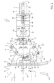
Figures 2 and3 show respective top plan views, with parts removed for clarity, of theFigure 1 braking unit in different operating conditions; -
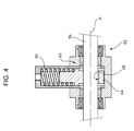
Figure 4 shows a larger-scale section along line IV-IV inFigure 2 ; -
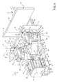
Figure 5 shows a view in perspective, with parts removed for clarity, of a different embodiment of a braking unit in accordance with the teachings of present invention; -
Figure 6 shows a top plan view of theFigure 5 braking unit; and -
Figure 7 shows a top plan view of theFigure 5 braking unit, with parts removed for clarity; -
Number 1 inFigures 1 to 3 indicates as a whole a braking unit for selectively stopping one or more items advanced by a conveyor 2 (Figure 1 ) along a transferring path P. - The
unit 1 is used to particular advantage in plants for the production ofpackaging containers 3 of pourable food products, such as the packaging plants previously described. - The
unit 1 can be used either withsingle packaging containers 3 or, as in the example shown, with multi-packs, i.e. packages, indicated withnumeral reference 4 hereafter, which are formed by shrink-wrapped groups of a given number (nine in the embodiment shown inFigures 1 and3 ) ofpackaging containers 3. - In particular, as visible in
Figures 1 and3 , eachpackage 4 has a parallelepiped shape and is, in turn, formed by parallelepiped-shaped packaging containers 3. It is clear that theunit 1 can be also used with packages formed by different types of packaging containers, such as gable-top containers, prismatic containers and so on. - Each package 4 (
Figure 1 ) is delimited by a front and arear surface 5, 6, respectively located downstream and upstream with reference to path P, by opposite lateral surfaces 7, 8, by a bottom surface 9 cooperating in use withconveyor 2 and by atop surface 10, opposite bottom surface 9. - The
unit 1 is mounted on afixed frame 11 and basically comprises: - a first and a
second braking element conveyor 2 and facing each other; - an
actuator 14 which can be selectively activated for movingbraking element 12 transversally with respect to path P and towardsbraking element 13 so as to clamp, between thebraking elements packages 4 to be braked; and - lever means 15 connecting
actuator 14 to brakingelement 12 and extendible towardsbraking element 13 as a result of the thrust exerted on thebraking element 12 by the package orpackages 4 to be braked. - As shown in
Figure 1 ,conveyor 2 is of the chain type and comprises atransport portion 16 defining a plane parallel to path P and on whichpackages 4 rest with their bottom surfaces 9 to be continuously advanced. -
Frame 11, only partially shown inFigures 1 to 3 , has anintermediate portion 20, which supportsconveyor 2, and oppositelateral portions conveyor 2. - In particular,
lateral portion 21 offrame 11 carriesbraking element 13, whilstlateral portion 22 carriesbraking element 12 and the other components ofunit 1. - As visible in
Figures 1 to 3 ,braking element 13 is secured tolateral portion 21 offrame 11 so as to have a fixed position. -
Braking element 12 can be moved closer to, or away from, brakingelement 13 and is arranged, together withactuator 14 and lever means 15, on top oflateral portion 22 offrame 11. - Braking
elements transport portion 16 ofconveyor 2 and havemain portions 23 parallel to each other andupstream end portions 24 converging towards themain portions 23 in the advancing direction ofpackages 4. - During the braking action,
braking elements packages 4 to be braked. -
Actuator 14 is defined, in the example shown, by a pneumatic cylinder, which comprises acasing 25, secured to the top oflateral portion 22 offrame 11 at a given distance frombraking element 12, and anoutput shaft 26 protruding from one side ofcasing 25, connected to brakingelement 12 through the interposition of lever means 15, and movable with respect to thecasing 25 along a direction A orthogonal tomain portions 23 ofbraking elements unit 1. - As shown in
Figures 1 to 3 ,output shaft 26 is coaxial to direction A. - Lever means 15 define, together with
braking element 12, a four-bar linkage 30, which comprises: - a
slider 31 connected tooutput shaft 26 ofactuator 14 and coupled, in a sliding manner, with aguide element 32 extending along direction A; and - a pair of
levers slider 31 to brakingelement 12. - As visible in
Figure 1 ,guide element 32 is formed by a bar having a T-shaped cross section and secured on top oflateral portion 22 offrame 11. -
Slider 31 comprises abottom portion 35 having a C-shaped cross section and coupled, in a sliding manner, ontoguide element 32.Slider 31 further comprises arear portion 36 connected tooutput shaft 26 ofactuator 14 and afront portion 37 protruding fromrear portion 36 towardsbraking element 12 and defining, with afront end surface 38, an abutment formain portion 23 ofbraking element 12, as it will be explained in more detail hereafter. - Each
lever rear portion 36 ofslider 31 and, at an opposite end, to arelative bracket 41 secured tomain portion 23 ofbraking element 12. - In particular, the opposite ends of each
lever corresponding pins rear portion 36 ofslider 31 and by therelative bracket 41 and have respective axes B, C orthogonal to direction A and to path P at the working zone ofunit 1. - Lever 33 is located upstream of
lever 34 with reference to the advancing direction ofpackages 4 along path P. - Each
lever intermediate portion 44 extending parallel topins arms 45 protruding orthogonally from the opposite ends ofintermediate portion 44 and hinged topin 42, and afurther arm 46 protruding from a central part ofintermediate portion 44, extending on the opposite side of the latter with respect toarms 45 and hinged topin 43. - As visible in
Figures 1 to 3 , levers 33, 34 extend obliquely frompins 42 topins 43 with respect to direction A and path P at the working zone ofunit 1. In practice, eachlever - More specifically, starting from
respective pins 42, levers 33, 34 are upstream oriented with reference to the advancing direction ofpackages 4 along path P. In other words, starting from therespective pins 42, levers 33, 34 are oriented in such a way that the prolongation of the upstream lever (33) towards path P never meets direction A. -
Brackets 41 are L-shaped in a top plan view (Figures 2 and3 ) and protrude frommain portion 23 ofbraking element 12 in a direction parallel to direction A towardslevers - Lever means 15 are normally arranged in a first operating condition (
Figures 1 and2 ), in which they have a given extension in the direction A so as to avoid any interference betweenbraking element 12 and thepackages 4 advanced along path P, and can be displaced, as a result of the thrust exerted by the package orpackages 4 to be braked onbraking element 12, in a second operating condition (Figure 3 ), in which they have an increased extension along direction A so as to reduce the distance of thebraking element 12 frombraking element 13. - In particular, the thrust exerted by the package or
packages 4 to be braked onbraking element 12 produces a rotation oflevers pins 42 so as to displace thebraking element 12 in the advancing direction ofpackages 4 and towardsbraking element 13. - By comparing
Figures 2 and3 , it is evident that levers 33, 34 reduce their angles with respect to direction A when lever means 15 are displaced from the first operating condition to the second operating condition. -
Unit 1 further comprises aspring device 47 for displacing lever means 15 in the first operating condition when the braking action ofunit 1 ceases;spring device 47 is arranged aboveslider 31 and comprises acasing 48 having oneend 49 hinged to thefront portion 37 ofslider 31, arod 50 protruding from anopposite end 52 ofcasing 48 and hinged to thepin 43 linked to lever 33, and a helical spring 53 (Figures 2 and3 ) housed insidecasing 48 and interposed between theend 49 thereof and therod 50.Spring device 47 extends along a direction diverging from brakingelement 12 towardsupstream end portion 24 thereof. - When lever means 15 are displaced from the first operating condition to the second operating condition, the
spring 53 is compressed and returns to the undeformed configuration upon release of the braking action. In this condition,main portion 23 ofbraking element 12 abuts againstfront end surface 38 ofslider 31. -
Unit 1 further comprises spring means 55 interposed betweenbraking element 12 andactuator 14. - In the embodiment shown in
Figures 1 to 4 , spring means 55 comprise ahelical spring 56 axially interposed between oneend 57 ofoutput shaft 26 and oneend 58 of acoaxial transmission shaft 59 connectingslider 31 toactuator 14. -
Output shaft 26 has one opposite end (not visible in the enclosed Figures) arranged inside casing 25, whilsttransmission shaft 57 has oneopposite end 60 connected torear portion 36 ofslider 31. - As shown in
Figures 1 to 3 ,spring 56 is housed inside asleeve element 61 secured tocasing 25 and protruding therefrom along direction A; end 57 ofoutput shaft 26 and end 58 oftransmission shaft 59 are both arranged withinsleeve element 61 and slidably coupled thereto. -
Unit 1 further comprises alocking device 62 for lockingtransmission shaft 59, and thereforeoutput shaft 26, in a given axial position. - When locking
device 62 exerts the locking action ontransmission shaft 59, any displacement ofbraking element 12 and lever means 15 is independent fromtransmission shaft 59 andoutput shaft 26. - As shown in detail in
Figure 4 , lockingdevice 62 basically comprises: - a
casing 63 secured to the top of thelateral portion 22 offrame 11 and fluid-tightly crossed, in a sliding manner along direction A, bytransmission shaft 59; - a
sleeve element 64 mounted withincasing 63 in a sliding manner along a radial direction with respect to direction A and having a throughhole 65 engaged with radial play bytransmission shaft 59; and - a
helical spring 66 radiallyloading sleeve element 64 so as to push part of the lateral edge ofhole 65 againsttransmission shaft 59, locking it axially. - Locking
device 62 is normally set in an active condition and can be pneumatically deactivated so as to compressspring 66 and allowsleeve element 64 to reach a centered or coaxial position with respect totransmission shaft 59, which is therefore free to move axially throughhole 65. - In use,
unit 1 is normally set in a condition in whichbraking element 12 does not interact with thepackages 4 advanced byconveyor 2. - When it is necessary to stop temporarily the package or
packages 4 moving along path P,actuator 14 is activated and lockingdevice 62 is deactivated so as to allowoutput shaft 26 andtransmission shaft 59 to be displaced along direction A. - As a result of the axial displacement of
shafts slider 31 is advanced in a corresponding manner along direction A by sliding alongguide element 32 andbraking element 12 is brought into contact with the package orpackages 4 to be braked. - During this movement, should the user put his fingers or other parts of his body between the
braking element 12 and the package orpackages 4 to be braked,spring 56 would compress. In this way, the only force acting on the user would be the load ofspring 56, which is designed to be suitable to clamp the package orpackages 4 to be braked between thebraking elements - At this point, i.e. after braking
element 12 has reached a contact position with the package orpackages 4 to be braked, lockingdevice 62 is left to exert its locking action ontransmission shaft 59. - The thrust exerted by the package or
packages 4 to be braked onbraking element 12 produces a rotation oflevers pins 42 so as to displace thebraking element 12 in the advancing direction ofpackages 4 and towardsbraking element 13. - In practice, lever means 15 reach a second operating condition (
Figure 3 ), in which they have an increased extension along direction A so as to reduce the distance of thebraking element 12 from brakingelement 13 and to increase the pressure on thepackages 4 to be braked. - If the queue of
packages 4 stopped byunit 1 increases, the thrust that they exert onbraking element 12 increases too and produces a further rotation oflevers pins 42 and a consequent additional displacement of thebraking element 12 in the advancing direction of thepackages 4 and towards thebraking element 13. In practice, the clamping force on thepackages 4 increases when the number ofpackages 4 forming the queue increases. - In order to allow the
packages 4 to advance again along path P, lockingdevice 62 is deactivated tofree transmission shaft 59, andactuator 14 is activated to movebraking element 12 away from thepackages 4. - In the meantime, the
spring 53 ofspring device 47, as it is no more subjected to the thrust ofpackages 4, can return to the undeformed configuration so displacing lever means 15 to the first operating condition. - Number 1' in
Figures 5 to 7 indicates as a whole a different embodiment of a braking unit in accordance with the teachings of the present invention;units 1 and 1' being similar to each other, the following description is limited to the differences between them, and using the same references, where possible, for identical or corresponding parts. - Unit 1' basically differs from
unit 1 by comprising a double four-bar linkage 30' in place of the single four-bar linkage 30, and spring means 55' acting on linkage 30' instead of cooperating withoutput shaft 26. Moreover, in this case, unit 1' lacks lockingdevice 62. - In particular, linkage 30' is defined by braking
element 12, by a slider 31', only formed byportions slider 31 and directly connected to end 57 ofoutput shaft 26, and by lever means 15' in turn comprising: - a pair of first parallel levers 33', 34' identical to
levers portion 36 of slider 31' through therespective pins 42 of axes B; - a pair of second
parallel levers main portion 23 ofbraking element 12; and - a
bar 72 hinged to levers 33', 34', 70 and 71 and extending parallel tomain portions 23 ofbraking elements - In particular, the
arms 45 of eachlever arm 46 of the relative lever 33' , 34' through a relative pin 43' of axis C parallel to axis B, whilst thearm 46 ofach lever relative pin 73 having an axis D parallel to axes B, C and carried by said bracket 41'. -
Lever 70 is located upstream oflever 71 with reference to the advancing direction ofpackages 4 along path P. -
Bar 72 has opposite ends hinged to pins 43'. - In this case, brackets 41' are formed by respective bars protruding from
main portion 23 ofbraking element 12 in a direction parallel to direction A towardslevers - As visible in
Figures 5 to 7 , levers 33', 34' extend obliquely frompins 42 to pins 43' with respect to direction A and path P at the working zone ofunit 1 and are downstream oriented with reference to the advancing direction ofpackages 4. In other words, starting fromrespective pins 42, levers 33', 34' are oriented in such a way that the prolongation of the downstream lever (34') towards path P never meets direction A. -
Levers unit 1. - Also in this case, lever means 15' are normally arranged in a first operating condition (
Figures 5 to 7 ), in which they have a given extension in the direction A so as to avoid any interference betweenbraking element 12 and thepackages 4 advanced along path P, and can be displaced, as a result of the thrust exerted by the package orpackages 4 to be braked onbraking element 12, in a second operating condition (not shown), in which they have an increased extension along direction A so as to reduce the distance of thebraking element 12 from brakingelement 13. - In particular, the thrust exerted by the package or
packages 4 to be braked onbraking element 12 produces, through the rotation oflevers braking element 12 in the advancing direction ofpackages 4 and towardsbraking element 13. - As shown in
Figures 5 to 7 , spring means 55' are interposed betweenbraking element 12 and slider 31'. - In particular, spring means 55' comprise a pair of
spring devices 75, identical tospring device 47 ofunit 1 and extending parallel to direction A and on opposite sides thereof; eachspring device 75 is arranged above one of levers 33', 34' and therelative lever relative pins - More specifically, each
spring device 75 comprises acasing 76 having oneend 77 hinged to therelative pin 42 carried by slider 31', arod 78 protruding from anopposite end 79 ofcasing 76 and hinged to therelative pin 73 carried by the relative bracket 41', and a helical spring 80 (Figure 5 ) housed insidecasing 76 and interposed between theend 77 thereof and therod 78. - With reference to
Figures 6 and7 , unit 1' further comprises anadditional spring device 81 for displacing lever means 15' in the first operating condition when the braking action of unit 1' ceases;spring device 81 is identical tospring devices 75, is arranged above slider 31' and extend parallel tomain portion 23 ofbraking elements - In particular,
spring device 81 comprises acasing 82 having oneend 83 hinged to slider 31', arod 84 protruding from anopposite end 85 ofcasing 82 and linked into a slot (not visible) of abracket 86 projecting frommain portion 23 ofbraking element 12, and ahelical spring 87 housed insidecasing 82 and interposed between theend 83 thereof and therod 84. - When lever means 15' are displaced from the first operating condition to the second operating condition, the
spring 87 is compressed and returns to the undeformed configuration upon release of the braking action. - The operation of unit 1' is completely analogous to the one of
unit 1. - When it is necessary to stop temporarily the package or
packages 4 moving along path P,actuator 14 is activated andoutput shaft 26 and slider 31' are moved along direction A in order to bringbraking element 12 into contact with the package orpackages 4 to be braked. - During this movement, should the user put his fingers or other parts of his body between the
braking element 12 and the package orpackages 4 to be braked, springs 80 ofspring devices 75 would compress. In this way, the only force acting on the user would be the load of springs 80, which is designed to be suitable to clamp the package orpackages 4 to be braked between thebraking elements - At this point, i.e. after braking
element 12 has reached a contact position with the package orpackages 4 to be braked, the thrust exerted by the package orpackages 4 to be braked onbraking element 12 produces, through the linkage 30', a displacement of thebraking element 12 in the advancing direction ofpackages 4 and towardsbraking element 13. - In practice, lever means 15' reach a second operating condition, in which they have an increased extension along direction A so as to reduce the distance of the
braking element 12 from brakingelement 13 and to increase the pressure on thepackages 4 to be braked. - If the queue of
packages 4 stopped by unit 1' increases, the thrust that they exert onbraking element 12 increases too and produces a further rotation oflevers braking element 12 in the advancing direction of thepackages 4 and towards thebraking element 13. In practice, the clamping force on thepackages 4 increases when the number ofpackages 4 forming the queue increases. - In order to allow the
packages 4 to advance again along path P,actuator 14 is activated to movebraking element 12 away from thepackages 4. - In the meantime, the
spring 87 ofspring device 81, as it is no more subjected to the thrust ofpackages 4, can return to the undeformed configuration so displacing lever means 15' to the first operating condition. - The advantages of
braking units 1, 1' according to the present invention will be clear from the foregoing description. - In particular,
braking units 1, 1' are very effective in stopping any number ofpackages 4 in a row without damaging them. As a matter of fact,units 1, are adapted to exert a clamping force on thepackages 4, which increases upon an increase of the number ofpackages 4 forming the queue. - As a consequence of this sort of "automatic" increase of the clamping force, it can be maintained at a relatively low level when the
braking units 1, 1' act on asingle package 4 or on afew packages 4 so as to not damage it or them. At the same time, thebraking units 1, 1' do not loose their effectiveness over a certain number ofpackages 4 in the row, but rather they become more effective thanks to the provision of the lever means 15, 15'. - Moreover, the
braking units 1, 1' are particularly safe for the user, since the only force that would act on the latter, should him put his fingers between thepackages 4 and thebraking element 12, would be the load of the spring means 55, 55'; in this way,braking units 1, 1' do not require any protection device around the working area. - Clearly, changes may be made to
braking units 1, 1' without, however, departing from the protective scope defined in the accompanying claims.
Claims (14)
- A braking unit (1, 1') for selectively stopping one or more items (4) advanced by a conveyor (2) along a transferring path (P), said unit (1, 1') being characterized by comprising:- a first and a second braking element (12, 13) arranged on opposite sides of said conveyor (2) and facing each other;- actuator means (14) which can be selectively activated for moving said first braking element (12) towards said second braking element (13) so as to clamp the item or items (4) to be braked between the first and second braking element (12, 13); and- lever means (15, 15') connecting said actuator means (14) to said first braking element (12) and extendible towards said second braking element (13) as a result of the thrust exerted on said first braking element (12) by the item or items (4) to be braked.
- A unit as claimed in claim 1, wherein said lever means (15, 15') are normally arranged in a first operating condition, in which they have a given extension in a direction (A) transversal to said path (P) at the working zone of the unit (1, 1') so as to avoid any interference between the first braking element (12) and the items (4) advanced along said path (P), and can be displaced, as a result of the thrust exerted by the item or items (4) to be braked on said first braking element (12), in a second operating condition, in which they have an increased extension along said direction (A) so as to reduce the distance between said first and second braking element (12, 13).
- A unit as claimed in claim 1 or 2, wherein it further comprises spring means (55, 55') interposed between said first braking element (12) and said actuator means (14).
- A unit as claimed in anyone of the foregoing claims, wherein it further comprises a slider (31, 31') connected to an output member (26) of said actuator means (14) and coupled in a sliding manner with guide means (32) extending along said direction (A).
- A unit as claimed in claim 4, wherein said lever means (15) define, together with said first braking element (12) and said slider (31), at least one four-bar linkage (30).
- A unit as claimed in claim 4 or 5, wherein said lever means (15) comprise a pair of levers (33, 34) hinged, on one side, to respective first pins (42) carried by said slider (31), and, on the other side, to respective second pins (43) carried by said first braking element (12); said first and second pins (42, 43) having axes orthogonal to said direction (A) and to said path (P) at the working zone of the unit (1).
- A unit as claimed in claim 6, wherein said levers (33, 34) extend obliquely from said first pins (42) to said second pins (43) with respect to said direction (A) and said path (P) at the working zone of the unit (1) and are upstream oriented with reference to the advancing direction of said items (4).
- A unit as claimed in anyone of the claims 4 to 7, wherein said spring means (55) comprise a spring element (56) interposed between said actuator means (14) and said slider (31).
- A unit as claimed in anyone of claims 4 to 8, wherein it further comprises releasable locking means (62) for locking said output member (26) of said actuator means (14) in a given axial position.
- A unit as claimed in claim 4, wherein said spring means (55') are interposed between said first braking element (12) and said slider (31').
- A unit as claimed in claim 4, wherein said lever means (15') define, together with said first braking element (12) and said slider (31'), a double four-bar linkage (30').
- A unit as claimed in claim 11, wherein said lever means (15') comprise:- a pair of first levers (33', 34') parallel to each other and hinged to first pins (42) carried by said slider (31') and having axes (B) orthogonal to said direction (A) and to said path (P) at the working zone of the unit (1');- a pair of second levers (70, 71) parallel to each other and hinged, on one side, to second pins (73) carried by said first braking element (12), and, on the other side, to the respective first levers (33', 34') through respective third pins (43') parallel to said first and second pins (42, 73); and- a bar (72) transversal to said first and second levers (33', 34', 70, 71) and having opposite ends hinged to said third pins (43').
- A unit as claimed in claim 12, wherein said spring means (55') comprise a pair of spring elements (80) extending parallel to said direction (A) and on opposite sides thereof and each of which is interposed between a relative one of said first pins (42) and a relative one of said second pins (73).
- A unit as claimed in anyone of claims 2 to 13, wherein it comprises additional spring means (47, 81) for displacing said lever means (15, 15') in the first operating condition when the braking action ceases.
Priority Applications (5)
| Application Number | Priority Date | Filing Date | Title |
|---|---|---|---|
| EP10174901.8A EP2426071B1 (en) | 2010-09-01 | 2010-09-01 | Conveying system with a braking unit |
| CN201180042054.9A CN103068701B (en) | 2010-09-01 | 2011-08-22 | Brake unit |
| US13/816,055 US9051131B2 (en) | 2010-09-01 | 2011-08-22 | Braking unit |
| JP2013526400A JP5814369B2 (en) | 2010-09-01 | 2011-08-22 | Brake unit |
| PCT/EP2011/064405 WO2012028485A1 (en) | 2010-09-01 | 2011-08-22 | A braking unit |
Applications Claiming Priority (1)
| Application Number | Priority Date | Filing Date | Title |
|---|---|---|---|
| EP10174901.8A EP2426071B1 (en) | 2010-09-01 | 2010-09-01 | Conveying system with a braking unit |
Publications (2)
| Publication Number | Publication Date |
|---|---|
| EP2426071A1 true EP2426071A1 (en) | 2012-03-07 |
| EP2426071B1 EP2426071B1 (en) | 2014-01-22 |
Family
ID=43531224
Family Applications (1)
| Application Number | Title | Priority Date | Filing Date |
|---|---|---|---|
| EP10174901.8A Not-in-force EP2426071B1 (en) | 2010-09-01 | 2010-09-01 | Conveying system with a braking unit |
Country Status (5)
| Country | Link |
|---|---|
| US (1) | US9051131B2 (en) |
| EP (1) | EP2426071B1 (en) |
| JP (1) | JP5814369B2 (en) |
| CN (1) | CN103068701B (en) |
| WO (1) | WO2012028485A1 (en) |
Families Citing this family (3)
| Publication number | Priority date | Publication date | Assignee | Title |
|---|---|---|---|---|
| US9004821B2 (en) * | 2013-03-09 | 2015-04-14 | Alliance Industrial Corporation | Air conveyor guide adjustment mechanism |
| CN106081230B (en) * | 2016-07-18 | 2018-11-13 | 西安科技大学 | One kind is for the vanning process transfer matic design of ballast packing box |
| IL271653B2 (en) * | 2019-12-22 | 2024-10-01 | Bright Machines Ltd | Adjustable conveyor belt |
Citations (5)
| Publication number | Priority date | Publication date | Assignee | Title |
|---|---|---|---|---|
| US1508369A (en) * | 1920-03-27 | 1924-09-09 | Standard Conveyor Co | Transfer gate for gravity conveyers |
| US3244322A (en) * | 1964-09-17 | 1966-04-05 | Owens Illinois Glass Co | Carton handling apparatus |
| US3527333A (en) * | 1967-09-29 | 1970-09-08 | Johns Nigrelli Johns | Article conveyor mechanism |
| DE3905955A1 (en) * | 1988-04-27 | 1989-11-09 | Nagema Veb K | Delivery device of a packaging machine |
| US20030111321A1 (en) * | 2001-12-14 | 2003-06-19 | Van Oss Steven J. | Conveyor clamping guide |
Family Cites Families (6)
| Publication number | Priority date | Publication date | Assignee | Title |
|---|---|---|---|---|
| JPS497829Y1 (en) * | 1970-09-26 | 1974-02-23 | ||
| JPS497829A (en) | 1972-05-12 | 1974-01-24 | ||
| US4174777A (en) * | 1978-02-24 | 1979-11-20 | A-T-O Inc. | Zero pressure accumulating conveyor and method |
| JP2603601Y2 (en) | 1993-08-18 | 2000-03-15 | 株式会社フジシール | Work stop device |
| JP2001163444A (en) | 1999-12-13 | 2001-06-19 | Sumitomo Kinzoku Kozan Siporex Kk | Equipment for fixing conveyed goods |
| FR2923099B1 (en) * | 2007-10-29 | 2009-12-11 | Areva T & D Ag | ELECTROMECHANICAL ACTUATOR WITH SPRING SPIRE SPRING-TYPE MECHANICAL BRAKE |
-
2010
- 2010-09-01 EP EP10174901.8A patent/EP2426071B1/en not_active Not-in-force
-
2011
- 2011-08-22 CN CN201180042054.9A patent/CN103068701B/en not_active Expired - Fee Related
- 2011-08-22 WO PCT/EP2011/064405 patent/WO2012028485A1/en not_active Ceased
- 2011-08-22 US US13/816,055 patent/US9051131B2/en not_active Expired - Fee Related
- 2011-08-22 JP JP2013526400A patent/JP5814369B2/en not_active Expired - Fee Related
Patent Citations (5)
| Publication number | Priority date | Publication date | Assignee | Title |
|---|---|---|---|---|
| US1508369A (en) * | 1920-03-27 | 1924-09-09 | Standard Conveyor Co | Transfer gate for gravity conveyers |
| US3244322A (en) * | 1964-09-17 | 1966-04-05 | Owens Illinois Glass Co | Carton handling apparatus |
| US3527333A (en) * | 1967-09-29 | 1970-09-08 | Johns Nigrelli Johns | Article conveyor mechanism |
| DE3905955A1 (en) * | 1988-04-27 | 1989-11-09 | Nagema Veb K | Delivery device of a packaging machine |
| US20030111321A1 (en) * | 2001-12-14 | 2003-06-19 | Van Oss Steven J. | Conveyor clamping guide |
Also Published As
| Publication number | Publication date |
|---|---|
| JP2013538766A (en) | 2013-10-17 |
| WO2012028485A1 (en) | 2012-03-08 |
| EP2426071B1 (en) | 2014-01-22 |
| CN103068701A (en) | 2013-04-24 |
| CN103068701B (en) | 2016-06-01 |
| US20130126301A1 (en) | 2013-05-23 |
| JP5814369B2 (en) | 2015-11-17 |
| US9051131B2 (en) | 2015-06-09 |
Similar Documents
| Publication | Publication Date | Title |
|---|---|---|
| EP2743192B1 (en) | A unit for sequencing and guiding items | |
| US8113335B2 (en) | Unit for grouping packages along a transfer path | |
| EP2586719B1 (en) | Folding unit and method for producing pourable food product packages | |
| EP1688375B1 (en) | Unit for grouping packages along a path | |
| EP1726526B1 (en) | Folding unit for pourable food product packaging machines | |
| EP2586716B1 (en) | Folding unit for pourable food product packaging machines | |
| US20100012457A1 (en) | Unit and method for grouping packages along a transfer path | |
| US9051131B2 (en) | Braking unit | |
| US10392137B2 (en) | Folding unit for producing packages of food products pourable into a tube of packaging material from sealed packs | |
| EP3202674B1 (en) | A jam detecting device, a method for detecting defective packages in a filling machine, a folding unit for producing packages of pourable food products in a filling machine, and a filling machine | |
| EP2316737A1 (en) | Separating unit for separating a batch of packages of a product which is pourable within a tube of packaging material from a row of packages, and related method | |
| EP3020642A1 (en) | Folding unit for producing folded packages from sealed packs | |
| HK1128447B (en) | Sequencing unit for opening devices to be glued to sealed packages of pourable food products | |
| HK1136806B (en) | Unit for grouping packages along a transfer path | |
| HK1128447A1 (en) | Sequencing unit for opening devices to be glued to sealed packages of pourable food products | |
| HK1117481B (en) | Unit for grouping packages along a path |
Legal Events
| Date | Code | Title | Description |
|---|---|---|---|
| AK | Designated contracting states |
Kind code of ref document: A1 Designated state(s): AL AT BE BG CH CY CZ DE DK EE ES FI FR GB GR HR HU IE IS IT LI LT LU LV MC MK MT NL NO PL PT RO SE SI SK SM TR |
|
| AX | Request for extension of the european patent |
Extension state: BA ME RS |
|
| PUAI | Public reference made under article 153(3) epc to a published international application that has entered the european phase |
Free format text: ORIGINAL CODE: 0009012 |
|
| 17P | Request for examination filed |
Effective date: 20120905 |
|
| 17Q | First examination report despatched |
Effective date: 20130131 |
|
| GRAP | Despatch of communication of intention to grant a patent |
Free format text: ORIGINAL CODE: EPIDOSNIGR1 |
|
| INTG | Intention to grant announced |
Effective date: 20130702 |
|
| GRAP | Despatch of communication of intention to grant a patent |
Free format text: ORIGINAL CODE: EPIDOSNIGR1 |
|
| INTG | Intention to grant announced |
Effective date: 20131004 |
|
| GRAS | Grant fee paid |
Free format text: ORIGINAL CODE: EPIDOSNIGR3 |
|
| GRAA | (expected) grant |
Free format text: ORIGINAL CODE: 0009210 |
|
| AK | Designated contracting states |
Kind code of ref document: B1 Designated state(s): AL AT BE BG CH CY CZ DE DK EE ES FI FR GB GR HR HU IE IS IT LI LT LU LV MC MK MT NL NO PL PT RO SE SI SK SM TR |
|
| REG | Reference to a national code |
Ref country code: GB Ref legal event code: FG4D |
|
| REG | Reference to a national code |
Ref country code: CH Ref legal event code: EP |
|
| REG | Reference to a national code |
Ref country code: AT Ref legal event code: REF Ref document number: 650693 Country of ref document: AT Kind code of ref document: T Effective date: 20140215 |
|
| REG | Reference to a national code |
Ref country code: IE Ref legal event code: FG4D |
|
| REG | Reference to a national code |
Ref country code: DE Ref legal event code: R096 Ref document number: 602010013245 Country of ref document: DE Effective date: 20140306 |
|
| REG | Reference to a national code |
Ref country code: NL Ref legal event code: VDEP Effective date: 20140122 |
|
| REG | Reference to a national code |
Ref country code: AT Ref legal event code: MK05 Ref document number: 650693 Country of ref document: AT Kind code of ref document: T Effective date: 20140122 |
|
| REG | Reference to a national code |
Ref country code: LT Ref legal event code: MG4D |
|
| PG25 | Lapsed in a contracting state [announced via postgrant information from national office to epo] |
Ref country code: LT Free format text: LAPSE BECAUSE OF FAILURE TO SUBMIT A TRANSLATION OF THE DESCRIPTION OR TO PAY THE FEE WITHIN THE PRESCRIBED TIME-LIMIT Effective date: 20140122 Ref country code: NO Free format text: LAPSE BECAUSE OF FAILURE TO SUBMIT A TRANSLATION OF THE DESCRIPTION OR TO PAY THE FEE WITHIN THE PRESCRIBED TIME-LIMIT Effective date: 20140422 Ref country code: IS Free format text: LAPSE BECAUSE OF FAILURE TO SUBMIT A TRANSLATION OF THE DESCRIPTION OR TO PAY THE FEE WITHIN THE PRESCRIBED TIME-LIMIT Effective date: 20140522 |
|
| PG25 | Lapsed in a contracting state [announced via postgrant information from national office to epo] |
Ref country code: ES Free format text: LAPSE BECAUSE OF FAILURE TO SUBMIT A TRANSLATION OF THE DESCRIPTION OR TO PAY THE FEE WITHIN THE PRESCRIBED TIME-LIMIT Effective date: 20140122 Ref country code: PT Free format text: LAPSE BECAUSE OF FAILURE TO SUBMIT A TRANSLATION OF THE DESCRIPTION OR TO PAY THE FEE WITHIN THE PRESCRIBED TIME-LIMIT Effective date: 20140522 Ref country code: AT Free format text: LAPSE BECAUSE OF FAILURE TO SUBMIT A TRANSLATION OF THE DESCRIPTION OR TO PAY THE FEE WITHIN THE PRESCRIBED TIME-LIMIT Effective date: 20140122 Ref country code: FI Free format text: LAPSE BECAUSE OF FAILURE TO SUBMIT A TRANSLATION OF THE DESCRIPTION OR TO PAY THE FEE WITHIN THE PRESCRIBED TIME-LIMIT Effective date: 20140122 Ref country code: NL Free format text: LAPSE BECAUSE OF FAILURE TO SUBMIT A TRANSLATION OF THE DESCRIPTION OR TO PAY THE FEE WITHIN THE PRESCRIBED TIME-LIMIT Effective date: 20140122 Ref country code: SE Free format text: LAPSE BECAUSE OF FAILURE TO SUBMIT A TRANSLATION OF THE DESCRIPTION OR TO PAY THE FEE WITHIN THE PRESCRIBED TIME-LIMIT Effective date: 20140122 Ref country code: CY Free format text: LAPSE BECAUSE OF FAILURE TO SUBMIT A TRANSLATION OF THE DESCRIPTION OR TO PAY THE FEE WITHIN THE PRESCRIBED TIME-LIMIT Effective date: 20140122 |
|
| PG25 | Lapsed in a contracting state [announced via postgrant information from national office to epo] |
Ref country code: LV Free format text: LAPSE BECAUSE OF FAILURE TO SUBMIT A TRANSLATION OF THE DESCRIPTION OR TO PAY THE FEE WITHIN THE PRESCRIBED TIME-LIMIT Effective date: 20140122 Ref country code: BE Free format text: LAPSE BECAUSE OF FAILURE TO SUBMIT A TRANSLATION OF THE DESCRIPTION OR TO PAY THE FEE WITHIN THE PRESCRIBED TIME-LIMIT Effective date: 20140122 Ref country code: HR Free format text: LAPSE BECAUSE OF FAILURE TO SUBMIT A TRANSLATION OF THE DESCRIPTION OR TO PAY THE FEE WITHIN THE PRESCRIBED TIME-LIMIT Effective date: 20140122 |
|
| REG | Reference to a national code |
Ref country code: DE Ref legal event code: R097 Ref document number: 602010013245 Country of ref document: DE |
|
| PG25 | Lapsed in a contracting state [announced via postgrant information from national office to epo] |
Ref country code: RO Free format text: LAPSE BECAUSE OF FAILURE TO SUBMIT A TRANSLATION OF THE DESCRIPTION OR TO PAY THE FEE WITHIN THE PRESCRIBED TIME-LIMIT Effective date: 20140122 Ref country code: CZ Free format text: LAPSE BECAUSE OF FAILURE TO SUBMIT A TRANSLATION OF THE DESCRIPTION OR TO PAY THE FEE WITHIN THE PRESCRIBED TIME-LIMIT Effective date: 20140122 Ref country code: EE Free format text: LAPSE BECAUSE OF FAILURE TO SUBMIT A TRANSLATION OF THE DESCRIPTION OR TO PAY THE FEE WITHIN THE PRESCRIBED TIME-LIMIT Effective date: 20140122 Ref country code: DK Free format text: LAPSE BECAUSE OF FAILURE TO SUBMIT A TRANSLATION OF THE DESCRIPTION OR TO PAY THE FEE WITHIN THE PRESCRIBED TIME-LIMIT Effective date: 20140122 |
|
| PG25 | Lapsed in a contracting state [announced via postgrant information from national office to epo] |
Ref country code: PL Free format text: LAPSE BECAUSE OF FAILURE TO SUBMIT A TRANSLATION OF THE DESCRIPTION OR TO PAY THE FEE WITHIN THE PRESCRIBED TIME-LIMIT Effective date: 20140122 Ref country code: SK Free format text: LAPSE BECAUSE OF FAILURE TO SUBMIT A TRANSLATION OF THE DESCRIPTION OR TO PAY THE FEE WITHIN THE PRESCRIBED TIME-LIMIT Effective date: 20140122 |
|
| PLBE | No opposition filed within time limit |
Free format text: ORIGINAL CODE: 0009261 |
|
| STAA | Information on the status of an ep patent application or granted ep patent |
Free format text: STATUS: NO OPPOSITION FILED WITHIN TIME LIMIT |
|
| 26N | No opposition filed |
Effective date: 20141023 |
|
| REG | Reference to a national code |
Ref country code: DE Ref legal event code: R097 Ref document number: 602010013245 Country of ref document: DE Effective date: 20141023 |
|
| PG25 | Lapsed in a contracting state [announced via postgrant information from national office to epo] |
Ref country code: MC Free format text: LAPSE BECAUSE OF FAILURE TO SUBMIT A TRANSLATION OF THE DESCRIPTION OR TO PAY THE FEE WITHIN THE PRESCRIBED TIME-LIMIT Effective date: 20140122 Ref country code: LU Free format text: LAPSE BECAUSE OF FAILURE TO SUBMIT A TRANSLATION OF THE DESCRIPTION OR TO PAY THE FEE WITHIN THE PRESCRIBED TIME-LIMIT Effective date: 20140901 |
|
| REG | Reference to a national code |
Ref country code: CH Ref legal event code: PL |
|
| GBPC | Gb: european patent ceased through non-payment of renewal fee |
Effective date: 20140901 |
|
| PG25 | Lapsed in a contracting state [announced via postgrant information from national office to epo] |
Ref country code: SI Free format text: LAPSE BECAUSE OF FAILURE TO SUBMIT A TRANSLATION OF THE DESCRIPTION OR TO PAY THE FEE WITHIN THE PRESCRIBED TIME-LIMIT Effective date: 20140122 |
|
| REG | Reference to a national code |
Ref country code: IE Ref legal event code: MM4A |
|
| REG | Reference to a national code |
Ref country code: FR Ref legal event code: PLFP Year of fee payment: 6 |
|
| PG25 | Lapsed in a contracting state [announced via postgrant information from national office to epo] |
Ref country code: CH Free format text: LAPSE BECAUSE OF NON-PAYMENT OF DUE FEES Effective date: 20140930 Ref country code: LI Free format text: LAPSE BECAUSE OF NON-PAYMENT OF DUE FEES Effective date: 20140930 Ref country code: GB Free format text: LAPSE BECAUSE OF NON-PAYMENT OF DUE FEES Effective date: 20140901 |
|
| PG25 | Lapsed in a contracting state [announced via postgrant information from national office to epo] |
Ref country code: IE Free format text: LAPSE BECAUSE OF NON-PAYMENT OF DUE FEES Effective date: 20140901 |
|
| PG25 | Lapsed in a contracting state [announced via postgrant information from national office to epo] |
Ref country code: SM Free format text: LAPSE BECAUSE OF FAILURE TO SUBMIT A TRANSLATION OF THE DESCRIPTION OR TO PAY THE FEE WITHIN THE PRESCRIBED TIME-LIMIT Effective date: 20140122 |
|
| PG25 | Lapsed in a contracting state [announced via postgrant information from national office to epo] |
Ref country code: GR Free format text: LAPSE BECAUSE OF FAILURE TO SUBMIT A TRANSLATION OF THE DESCRIPTION OR TO PAY THE FEE WITHIN THE PRESCRIBED TIME-LIMIT Effective date: 20140423 Ref country code: BG Free format text: LAPSE BECAUSE OF FAILURE TO SUBMIT A TRANSLATION OF THE DESCRIPTION OR TO PAY THE FEE WITHIN THE PRESCRIBED TIME-LIMIT Effective date: 20140122 Ref country code: MT Free format text: LAPSE BECAUSE OF FAILURE TO SUBMIT A TRANSLATION OF THE DESCRIPTION OR TO PAY THE FEE WITHIN THE PRESCRIBED TIME-LIMIT Effective date: 20140122 |
|
| PG25 | Lapsed in a contracting state [announced via postgrant information from national office to epo] |
Ref country code: HU Free format text: LAPSE BECAUSE OF FAILURE TO SUBMIT A TRANSLATION OF THE DESCRIPTION OR TO PAY THE FEE WITHIN THE PRESCRIBED TIME-LIMIT; INVALID AB INITIO Effective date: 20100901 Ref country code: TR Free format text: LAPSE BECAUSE OF FAILURE TO SUBMIT A TRANSLATION OF THE DESCRIPTION OR TO PAY THE FEE WITHIN THE PRESCRIBED TIME-LIMIT Effective date: 20140122 |
|
| REG | Reference to a national code |
Ref country code: FR Ref legal event code: PLFP Year of fee payment: 7 |
|
| REG | Reference to a national code |
Ref country code: FR Ref legal event code: PLFP Year of fee payment: 8 |
|
| PGFP | Annual fee paid to national office [announced via postgrant information from national office to epo] |
Ref country code: IT Payment date: 20170925 Year of fee payment: 8 Ref country code: FR Payment date: 20170714 Year of fee payment: 8 Ref country code: DE Payment date: 20170830 Year of fee payment: 8 |
|
| PG25 | Lapsed in a contracting state [announced via postgrant information from national office to epo] |
Ref country code: MK Free format text: LAPSE BECAUSE OF FAILURE TO SUBMIT A TRANSLATION OF THE DESCRIPTION OR TO PAY THE FEE WITHIN THE PRESCRIBED TIME-LIMIT Effective date: 20140122 |
|
| PG25 | Lapsed in a contracting state [announced via postgrant information from national office to epo] |
Ref country code: AL Free format text: LAPSE BECAUSE OF FAILURE TO SUBMIT A TRANSLATION OF THE DESCRIPTION OR TO PAY THE FEE WITHIN THE PRESCRIBED TIME-LIMIT Effective date: 20140122 |
|
| REG | Reference to a national code |
Ref country code: DE Ref legal event code: R119 Ref document number: 602010013245 Country of ref document: DE |
|
| PG25 | Lapsed in a contracting state [announced via postgrant information from national office to epo] |
Ref country code: IT Free format text: LAPSE BECAUSE OF NON-PAYMENT OF DUE FEES Effective date: 20180901 Ref country code: DE Free format text: LAPSE BECAUSE OF NON-PAYMENT OF DUE FEES Effective date: 20190402 |
|
| PG25 | Lapsed in a contracting state [announced via postgrant information from national office to epo] |
Ref country code: FR Free format text: LAPSE BECAUSE OF NON-PAYMENT OF DUE FEES Effective date: 20180930 |