EP2425981A2 - Holder having detachable liquid housing container, and liquid housing container - Google Patents
Holder having detachable liquid housing container, and liquid housing container Download PDFInfo
- Publication number
- EP2425981A2 EP2425981A2 EP20110179717 EP11179717A EP2425981A2 EP 2425981 A2 EP2425981 A2 EP 2425981A2 EP 20110179717 EP20110179717 EP 20110179717 EP 11179717 A EP11179717 A EP 11179717A EP 2425981 A2 EP2425981 A2 EP 2425981A2
- Authority
- EP
- European Patent Office
- Prior art keywords
- wall surface
- surface portion
- holder
- housing container
- liquid
- Prior art date
- Legal status (The legal status is an assumption and is not a legal conclusion. Google has not performed a legal analysis and makes no representation as to the accuracy of the status listed.)
- Granted
Links
- 239000007788 liquid Substances 0.000 title claims abstract description 230
- 230000001105 regulatory effect Effects 0.000 claims description 66
- 230000007423 decrease Effects 0.000 claims description 5
- 238000003825 pressing Methods 0.000 claims description 3
- 238000000034 method Methods 0.000 description 32
- 238000010586 diagram Methods 0.000 description 27
- 238000001514 detection method Methods 0.000 description 20
- 230000003287 optical effect Effects 0.000 description 13
- 230000033228 biological regulation Effects 0.000 description 12
- 230000003247 decreasing effect Effects 0.000 description 12
- 230000007246 mechanism Effects 0.000 description 11
- 238000003860 storage Methods 0.000 description 4
- 239000004743 Polypropylene Substances 0.000 description 3
- 238000009434 installation Methods 0.000 description 3
- -1 polypropylene Polymers 0.000 description 3
- 229920001155 polypropylene Polymers 0.000 description 3
- 229920003002 synthetic resin Polymers 0.000 description 3
- 239000000057 synthetic resin Substances 0.000 description 3
- 230000008901 benefit Effects 0.000 description 2
- 239000006260 foam Substances 0.000 description 2
- 230000012447 hatching Effects 0.000 description 2
- 238000004519 manufacturing process Methods 0.000 description 2
- 239000011368 organic material Substances 0.000 description 2
- 229910001220 stainless steel Inorganic materials 0.000 description 2
- 239000010935 stainless steel Substances 0.000 description 2
- 238000000018 DNA microarray Methods 0.000 description 1
- 238000013459 approach Methods 0.000 description 1
- 230000004888 barrier function Effects 0.000 description 1
- 230000015556 catabolic process Effects 0.000 description 1
- 239000003086 colorant Substances 0.000 description 1
- 230000002950 deficient Effects 0.000 description 1
- 230000000694 effects Effects 0.000 description 1
- 239000007772 electrode material Substances 0.000 description 1
- 239000012530 fluid Substances 0.000 description 1
- 230000006872 improvement Effects 0.000 description 1
- 238000003780 insertion Methods 0.000 description 1
- 230000037431 insertion Effects 0.000 description 1
- 239000004973 liquid crystal related substance Substances 0.000 description 1
- 239000000463 material Substances 0.000 description 1
- 239000004745 nonwoven fabric Substances 0.000 description 1
- 238000005192 partition Methods 0.000 description 1
- 230000008569 process Effects 0.000 description 1
- 230000009467 reduction Effects 0.000 description 1
- 230000004044 response Effects 0.000 description 1
Images


Classifications
-
- B—PERFORMING OPERATIONS; TRANSPORTING
- B41—PRINTING; LINING MACHINES; TYPEWRITERS; STAMPS
- B41J—TYPEWRITERS; SELECTIVE PRINTING MECHANISMS, i.e. MECHANISMS PRINTING OTHERWISE THAN FROM A FORME; CORRECTION OF TYPOGRAPHICAL ERRORS
- B41J2/00—Typewriters or selective printing mechanisms characterised by the printing or marking process for which they are designed
- B41J2/005—Typewriters or selective printing mechanisms characterised by the printing or marking process for which they are designed characterised by bringing liquid or particles selectively into contact with a printing material
- B41J2/01—Ink jet
- B41J2/17—Ink jet characterised by ink handling
- B41J2/175—Ink supply systems ; Circuit parts therefor
- B41J2/17503—Ink cartridges
- B41J2/1752—Mounting within the printer
- B41J2/17523—Ink connection
-
- B—PERFORMING OPERATIONS; TRANSPORTING
- B41—PRINTING; LINING MACHINES; TYPEWRITERS; STAMPS
- B41J—TYPEWRITERS; SELECTIVE PRINTING MECHANISMS, i.e. MECHANISMS PRINTING OTHERWISE THAN FROM A FORME; CORRECTION OF TYPOGRAPHICAL ERRORS
- B41J2/00—Typewriters or selective printing mechanisms characterised by the printing or marking process for which they are designed
- B41J2/005—Typewriters or selective printing mechanisms characterised by the printing or marking process for which they are designed characterised by bringing liquid or particles selectively into contact with a printing material
- B41J2/01—Ink jet
- B41J2/17—Ink jet characterised by ink handling
- B41J2/175—Ink supply systems ; Circuit parts therefor
- B41J2/17503—Ink cartridges
- B41J2/1752—Mounting within the printer
Definitions
- the present invention relates to a holder having a detachable liquid housing container, and a liquid housing container.
- a printer which is one example of a liquid ejecting apparatus ejects an ink from a print head to a subject to be printed (for example, printing paper) and performs printing.
- the technique of using an ink cartridge containing an ink therein is known as an ink supplying technique for the print head (for example, JP-A-2006-142483 ).
- the ink is supplied from the ink cartridge to the print head by mounting the ink cartridge to a holder to which the print head is installed.
- the holder may be formed to be detachable from the ink cartridge so that a user may exchange the ink cartridge when the amount of ink is deficient in the ink cartridge.
- JP-A-2007-230248 and JP-A-2010-23458 are also examples of the related art.
- a part of the ink cartridge may contact the inner wall surface of the holder before the ink cartridge is mounted, which may disturb the insertion of the ink cartridge.
- An advantage of some aspects of the invention is to provide a holder to which the liquid housing container may be detachably mounted, which has an improved manipulation in attaching or detaching the liquid housing container.
- another advantage of some aspects of the invention is to provide a liquid housing container detachably mounted to the holder, which has an improved manipulation for attachment to and detachment from the holder.
- the invention is directed to solve at least a part of the above problems and it may be implemented as the following aspects and applications.
- a holder is provided to a liquid ejecting device having a head for ejecting a liquid and a liquid housing container capable of storing a liquid to be supplied to the head is attachable to or detachable from the holder, wherein the holder has a rotation point for rotating the mounted liquid housing container in a predetermined direction so as to be detached from the holder.
- the holder of Application 1 since the holder has the rotation point for detaching the liquid housing container, a user may easily detach the liquid housing container from the holder by rotating the liquid housing container.
- the holder according to Application 1 further includes a device-side bottom wall surface portion which forms a bottom surface; a device-side engagement unit engaged with the liquid housing container to regulate movement of the liquid housing container; and an opposite wall surface portion installed to stand from the device-side bottom wall surface portion and located to face the device-side engagement unit while the device-side bottom wall surface portion is interposed therebetween, wherein the rotation point is formed at the opposite wall surface portion so that the liquid housing container rotates in the predetermined direction centered around the rotation point by adding a force to the liquid housing container in a direction in which the engagement is released.
- the manipulation for releasing the engagement of the holder and the liquid housing container and the manipulation for detaching the liquid housing container from the holder may be performed in series. By doing so, the manipulation when the liquid housing container is detached from the holder may be improved.
- the liquid housing container attached to or detached from the holder includes a container body having a first wall surface portion which becomes a bottom surface when the liquid housing container is mounted to the holder, a second wall surface portion connected to the first wall surface portion, and a third wall surface portion connected to the first wall surface portion and facing the second wall surface portion, wherein, with respect to a usage posture of the liquid ejecting device, the opposite wall surface portion includes: an opposite surface extending upwards from the device-side bottom wall surface portion, the opposite surface being approximately parallel with an outer surface of the third wall surface portion when the liquid housing container is mounted; and an extension surface which extends from an upper end of the opposite surface in a direction away from the outer surface of the third wall surface portion, wherein the rotation point is defined by a border of the opposite surface and the extension surface.
- the rotation point may be easily formed using the opposite wall surface portion of the holder.
- the liquid housing container attached to or detached from the holder includes a container body having a first wall surface portion which becomes a bottom surface when the liquid housing container is mounted to the holder, a second wall surface portion connected to the first wall surface portion, and a third wall surface portion connected to the first wall surface portion and facing the second wall surface portion, wherein, with respect to a usage posture of the liquid ejecting device, the opposite wall surface portion includes an opposite surface which extends upward from the device-side bottom wall surface portion and which is approximately parallel with an outer surface of the third wall surface portion when the liquid housing container is mounted, and wherein a space portion is formed above the opposite surface to receive a part of the liquid housing container so that the liquid housing container is allowed to rotate.
- the rotation point may be easily formed by means of the space portion and the opposite surface which is one surface of the opposite wall surface portion.
- the rotation point is located below an engagement point where the liquid housing container is engaged with the device-side engagement unit.
- the engagement of the holder and the liquid housing container may be released, and the liquid housing container may be rotated and detached from the holder.
- the manipulation when the liquid housing container is detached from the holder may be further improved.
- the opposite wall surface portion has a hole portion located closer to the device-side bottom wall surface portion than the rotation point so that a protrusion unit provided to the liquid housing container is inserted thereto to regulate movement of the liquid housing container after being mounted.
- the movement of the liquid housing container may be regulated by the hole portion after the liquid housing container is mounted, and the protrusion unit of the liquid housing container may be pulled out from the hole portion by rotating the liquid housing container in order to detach the liquid housing container.
- the opposite wall surface portion has a guide channel for guiding the protrusion unit to the hole portion while regulating the movement of the liquid housing container in a width direction by the protrusion unit, when the liquid housing container is mounted.
- a user may easily guide the protrusion unit of the liquid housing container to the hole portion of the holder by inserting the protrusion unit of the liquid housing container into the guide channel. Therefore, the manipulation when the liquid housing container is mounted to the holder may be improved.
- the guide channel is formed over the hole portion from an upper end of the opposite wall surface portion.
- the upper end of the guide channel is located at the upper end of the opposite wall surface portion, a user may easily insert the protrusion unit of the liquid housing container into the guide channel.
- the width of the upper end of the guide channel is greater than a width of the lower end of the guide channel.
- the upper end of the guide channel has a greater width, a user may more easily insert the protrusion unit of the liquid housing container into the guide channel.
- the width of the guide channel monotonously decreases as the hole portion gets closer.
- a user may easily insert the protrusion unit of the liquid housing container into the guide channel and may accurately guide the protrusion unit toward the hole portion.
- the guide channel has a lower guide channel having a tapered shape whose width gradually decreases as the hole portion gets closer.
- a user may smoothly guide the protrusion unit of the liquid housing container to the hole portion by means of the lower guide channel.
- the lower end of the guide channel has the same width as the width of the hole portion.
- the protrusion unit of the liquid housing container may be more smoothly guided from the guide channel to the hole portion.
- a channel bottom wall surface portion which forms a bottom surface of the guide channel and is opposite to the liquid housing container has a deformation unit which is elastically deformable in the depth direction of the guide channel, and with respect to a usage posture of the liquid ejecting device, the lower end of the deformation unit may reach the hole portion.
- the possibility that the movement of the liquid housing container in the holder is restricted may be decreased.
- the upper end of the deformation unit reaches a location higher than an intersection point where the channel bottom wall surface portion intersects a trajectory along which the protrusion unit rotates centered around an engagement point where the liquid housing container is engaged, before the protrusion unit of the liquid housing container is inserted into the hole portion, in a case where a container-side regulating unit of the liquid housing container which is to be engaged with the device-side engagement unit is engaged with the device-side engagement unit.
- the deformation unit is obtained by forming notches at both ends of the channel bottom wall surface portion.
- the deformation unit may be formed with a simple configuration by forming notches at both ends of the channel bottom wall surface portion.
- the device-side bottom wall surface portion includes a first device-side regulating unit which regulates the movement of the liquid housing container at least in a width direction by cooperating with a first regulating unit of the liquid housing container.
- the movement of the liquid housing container after being mounted may be suppressed.
- the first device-side regulating unit has a protrusive shape into which the first regulating unit which is a notch is inserted.
- the notch for regulating the movement in the width direction is installed to the liquid housing container which moves with respect to the holder when being mounted, the possibility that the mounting operation of the liquid housing container is restricted may be decreased rather than the case where the protrusion unit is installed instead of the notch.
- a liquid ejecting device has the holder according to any one of Applications 1 to 17.
- liquid ejecting device of Application 18 it is possible to provide a liquid ejecting device equipped with the holder with an improved manipulation when the liquid housing container is attached or detached.
- a liquid housing container is attachable to and detachable from a liquid ejecting device having a head for ejecting a liquid
- the liquid housing container including: a container body which forms a liquid receiving chamber for receiving a liquid therein and includes a first wall surface portion which becomes a bottom surface when the liquid ejecting device is mounted to a holder, a second wall surface portion connected to the first wall surface portion, and a third wall surface portion connected to the first wall surface portion to face the second wall surface portion; and an elastic portion having one end mounted to the second wall surface portion and having elasticity, the elastic portion being used for attachment to or detachment from the holder, wherein the elastic portion includes: a container-side regulating unit engaged with the holder to regulate the movement of the liquid housing container; and an engagement releasing unit provided above the container-side regulating unit and elastically deformed by an external force added thereto in a direction of pressing against the second wall surface portion to release the engagement, the engagement releasing unit allowing the liquid housing container to be detached from the
- the liquid housing container may be rotated to release the engagement of the liquid housing container by the engagement releasing unit and to detach the liquid housing container from the holder.
- the engagement releasing unit includes a first side surface opposite to the second wall surface portion and a second side surface opposite to the first side surface, and, in a case where the first side surface contacts the second wall surface portion, the second side surface is formed to be closer to the rotation point from the upper end to the lower end with respect to the direction in which the second and third wall surface portions are opposite.
- the second side surface is formed to be closer to the rotation point from the upper end to the lower end. Therefore, by applying an external force to the engagement releasing unit in the direction approaching the second wall surface portion (the length direction of the liquid housing container), the force in the rotation direction for rotating and detaching the liquid housing container may be efficiently transferred to the engagement releasing unit. By doing so, the liquid housing container may be rotated by the operation for releasing the engagement so that the liquid housing container may be easily detached from the holder.
- the invention may be implemented in various ways, and in addition to the liquid ejecting device equipped with the holder and the liquid housing container, the invention may be implemented as a method for manufacturing the holder having the above distinctive configuration and a method for manufacturing the liquid housing container having the above distinctive configuration.
- Fig. 1 is a schematic diagram showing a liquid ejecting apparatus.
- Fig. 2 is a perspective view showing an appearance of a holder to which a cartridge is mounted.
- Figs. 3A to 3D are first diagrams for illustrating the cartridge.
- Figs. 4A to 4C are second diagrams for illustrating the cartridge.
- Figs. 5A and 5B are diagrams for illustrating a circuit board.
- Figs. 6A and 6B are diagrams for illustrating a holder.
- Figs. 7A and 7B are diagrams for illustrating a detailed configuration of an opposite wall surface portion.
- Fig. 8 is a sectional view taken along the line VIII-VIII of Fig. 6A .
- Figs. 9A and 9B are diagrams for illustrating a mounted state of the cartridge.
- Figs. 10A and 10B are second diagrams for illustrating a mounted state of the cartridge.
- Figs. 11A and 11B are diagrams for illustrating the state after the mounting.
- Figs. 12A and 12B are diagrams for illustrating a detached state of the cartridge.
- Figs. 13A and 13B are second diagrams for illustrating a detached state of the cartridge.
- Figs. 14A to 14C are diagrams for illustrating a mounting manner in a separate method.
- Figs. 15A and 15B are diagrams for illustrating a mounting manner in a separate method.
- Figs. 16A and 16B are diagrams for illustrating a cartridge of a second embodiment.
- Figs. 17A to 17E are diagrams for illustrating modified shapes of the first modified example.
- Fig. 1 is a schematic diagram showing a liquid ejecting apparatus 1 having a liquid housing container 10 and a holder 20 as a first embodiment of the invention.
- the liquid ejecting apparatus 1 is an ink-jet printer 1 (hereinafter, referred to as just a "printer 1") which ejects an ink to a printing paper PA to perform printing.
- the printer 1 includes an ink cartridge 10 serving as a liquid housing container, a holder 20, a first motor 52, a second motor 50, a control unit 60, a manipulation unit 70, a predetermined interface 72, and an optical detection device 90.
- the ink cartridge 10 is simply called a "cartridge 10".
- the holder 20 has a print head (not shown) for ejecting an ink to the printing paper PA and its opposite side.
- the cartridge 10 is detachably loaded to the holder 20.
- an ink of cyan, magenta, yellow or the like is received, respectively.
- the ink received in the cartridge 10 is supplied to the print head of the holder 20 so that the ink is ejected to the printing paper PA.
- the first motor 52 drives the holder 20 in a main scanning direction.
- the second motor 50 feeds the printing paper PA in a sub-scanning direction.
- the control unit 60 controls overall operations of the printer 1.
- the optical detection device 90 is fixed at a predetermined location. When the holder 20 is moved to a predetermined location, the optical detection device 90 irradiates light toward the cartridge 10 in order to detect the remaining amount of the ink. In addition, the details will be described later.
- the control unit 60 controls the first motor 52, the second motor 50 and the print head based on printing data received from a computer 80 or the like connected thereto via the predetermined interface 72 to perform printing.
- the control unit 60 is connected to the manipulation unit 70 to receive various manipulations from a user.
- Fig. 2 is a perspective view showing an appearance of the holder 20 to which the cartridge 10 is mounted. For ease of description, Fig. 2 shows that one cartridge 10 is mounted to the holder 20. In addition, in order to specify directions, X, Y and Z axes orthogonal to each other are depicted in Fig. 2 . The X, Y and Z axes orthogonal to each other are also given to following figures as necessary.
- the holder 20 is configured so that four cartridges 10 may be mounted.
- the number of cartridges 10 which can be mounted to the holder 20 is not limited to four, and the configuration of the holder 20 may be changed according to the number of required cartridges 10.
- the Z-axis direction becomes a vertical direction
- the negative Z-axis negative direction becomes a vertical downward direction
- the main scanning direction of the printer 1 becomes a Y-axis direction.
- the holder 20 has a liquid supply tube 240.
- the liquid supply tube 240 communicates the print head of the holder 20 with the cartridge 10.
- the ink in the cartridge 10 is communicated with the print head via the liquid supply tube 240.
- an elastic member 242 is installed around the liquid supply tube 240 so that the ink does not leak out.
- the cartridge 10 has a lever 120 which is an elastic portion that is elastically deformed. A user may detach the cartridge 10 from the holder 20 by manipulating the elastic portion 120. In addition, the attaching/detaching manipulation of the cartridge 10 to/from the holder 20 will be described in detail later.
- Figs. 3A to 3D are drawings for illustrating the cartridge 10.
- Fig. 3A is a side view of the cartridge 10.
- Fig. 3B is a front view of the cartridge 10.
- Fig. 3C is a rear view of the cartridge 10.
- Fig. 3D is a bottom view of the cartridge 10.
- Figs. 4A to 4C are second drawings for illustrating the cartridge 10.
- Fig. 4A is a sectional view taken along the line IVA-IVA of Fig. 3B .
- Figs. 4B and 4C are drawings for illustrating a method for detecting a remaining amount of ink.
- the sectional view of the cartridge 10 taken along the line IVBC-IVBC of Fig. 4A is shown.
- the cartridge 10 includes a container body 100, a lever 120, a liquid supply hole 110, a circuit board 130, and a prism unit 170t.
- the container body 100, the lever 120 and the liquid supply hole 110 are formed with a synthetic resin such as polypropylene or the like.
- the container body 100 has a first wall surface portion (also called a “bottom surface portion”) 100a, a second wall surface portion (also called a “front surface portion”) 100b, a third wall surface portion (also called a “rear surface portion”) 100c, a fourth wall surface portion (also called an "upper surface portion”) 100d, a fifth wall surface portion (also called a “left side surface portion”) 100e, and a sixth wall surface portion (also called a "right side surface portion”) 100f.
- the container body 100 has a liquid receiving chamber 180 formed by the first to sixth wall surface portions 100a to 100f to receive an ink therein ( Fig. 3A ).
- the first wall surface portion 100a is a wall surface portion at the Z-axis negative direction with respect to the liquid receiving chamber 180.
- the second wall surface portion 100b is a wall surface portion at the X-axis positive direction with respect to the liquid receiving chamber 180.
- the third wall surface portion 100c is a wall surface portion at the X-axis negative direction with respect to the liquid receiving chamber 180.
- the fourth wall surface portion 100d is a wall surface portion at the Z-axis positive direction with respect to the liquid receiving chamber 180.
- the fifth wall surface portion 100e is a wall surface portion at the Y-axis positive direction with respect to the liquid receiving chamber 180.
- the sixth wall surface portion 100f is a wall surface portion at the Y-axis negative direction with respect to the liquid receiving chamber 180.
- the direction (Z-axis direction) in which the first wall surface portion 100a is opposite to the fourth wall surface portion 100d is set to be the height direction.
- the direction (X-axis direction) in which the second wall surface portion 100b is opposite to the third wall surface portion 100c is set to be the length direction.
- the direction (Y-axis direction) in which the fifth wall surface portion 100e is opposite to the sixth wall surface portion 100f is set to be the width direction.
- the first wall surface portion 100a configures an approximately rectangular bottom surface at both inner and outer surfaces with respect to a mounting posture to the holder 20.
- the fourth wall surface portion 100d is a wall surface portion opposite to the first wall surface portion 100a and configures an approximately rectangular top surface at both inner and outer surfaces with respect to the mounting posture.
- the outer surfaces of the first and fourth wall surface portions 100a and 100d become parallel surfaces with respect to the mounting posture.
- the second, third, fifth and sixth wall surface portions 100b, 100c, 100e and 100f are respectively connected to sides (four sides) of the first and fourth wall surface portions 100a and 100d.
- the second, third, fifth and sixth wall surface portions 100b, 100c, 100e and 100f are installed to stand from the first wall surface portion 100a.
- the third, fifth and sixth wall surface portions 100c, 100e and 100f perpendicularly intersect the first and fourth wall surface portions 100a and 100d.
- the outer surface of each wall surface portion 100c, 100e and 100f is perpendicular to the horizontal surface with respect to the mounting posture.
- the second wall surface portion 100b is opposite to the third wall surface portion 100c.
- the fifth wall surface portion 100e is opposite to the sixth wall surface portion 100f.
- the second wall surface portion 100b has a first vertical wall portion 100b1, a slanted wall portion 100b2 and a second vertical wall portion 100b3.
- the first vertical wall portion 100b1 is located at the lowermost region of the second wall surface portion 100b in a right vertical direction and stands in a right upward direction from the first wall surface portion 100a.
- the second vertical wall portion 100b3 is located at the uppermost region of the second wall surface portion 100b and is perpendicular to the fourth wall surface portion 100d.
- the slanted wall portion 100b2 has one end connected to the first vertical wall portion 100b1 and the other end connected to the second vertical wall portion 100b3.
- the slanted wall portion 100b2 is slanted so that the ink near the second wall surface portion 100b of the liquid receiving chamber 180 flows toward the liquid supply hole 110.
- the slanted wall portion 100b2 has an inner surface 100b2a which is slanted closer to the liquid supply hole 110 from the other end which is an upper end to one end which is a lower end.
- the outer surface of the slanted wall portion 100b2 is also slanted similarly to the inner surface 100b2a.
- the liquid supply hole 110 is installed in the first wall surface portion 100a so that the ink in the liquid receiving chamber 180 flows outwards.
- the liquid supply hole 110 is installed at a partial center of the first wall surface portion 100a, at a portion closer to the third wall surface portion 100c rather than the second wall surface portion 100b.
- the liquid supply hole 110 communicates with a flow channel 114 formed in the first wall surface portion 100a so that the ink in the liquid receiving chamber 180 flows outwards (toward the print head, in this embodiment).
- a sponge foam 112 is disposed in the liquid supply hole 110 to prevent the ink from leaking out of the liquid supply hole 110.
- the prism unit 170t is further disposed at the first wall surface portion 100a.
- the prism unit 170t is formed transparently by polypropylene.
- the prism unit 170t has a prism 170 used for detecting a remaining amount of ink.
- the prism 170 has a right isosceles triangular prism shape and is disposed so that a reflective surface 170f ( Figs. 4B and 4C ) is located in the liquid receiving chamber 180.
- a reflective surface 170f Figs. 4B and 4C
- the prism 170 is disposed to contact the inner surface of the second wall surface portion 100b (in detail, the first vertical wall portion 100b1). By disposing as described above, it is possible to prevent the ink flowing from the second wall surface portion 100b to the liquid supply hole 110 from being blocked by the prism 170. By doing so, the remaining amount of ink staying in the liquid receiving chamber 180 may be reduced so that the ink may be consumed efficiently.
- the prism 170 reflects light variously in response to the refractive index of the fluid which contacts the reflective surface 170f.
- the light irradiated from a light emitting element 92 is reflected by the reflective surface 170f of the prism 170 and is incident to a light receiving element 94 due to the difference in refractive indexes of the prism 170 and the air.
- Fig. 4B in a case where the remaining amount of ink decreases so that the reflective surface 170f contacts the air, the light irradiated from a light emitting element 92 is reflected by the reflective surface 170f of the prism 170 and is incident to a light receiving element 94 due to the difference in refractive indexes of the prism 170 and the air.
- the remaining amount of ink may be detected by measuring the light which is incident to the light receiving element 94.
- a notch (channel) 140 is formed in the first vertical wall portion 100b1 of the second wall surface portion 100b.
- the notch 140 is installed at a position closer to the first wall surface portion 100a than a position where a terminal group 130t is installed.
- the notch 140 is installed at a location closer to the first wall surface portion 100a than a location where the terminal group 130t is installed.
- the notch 140 is installed at the approximate center of the first vertical wall portion 100b1 in the width direction.
- the circuit board 130 having the terminal group 130t (which will be described later in detail) is installed to the slanted wall portion 100b2 of the second wall surface portion 100b.
- the notch 140 is installed to partially overlap the circuit board 130.
- the circuit board 130 is located right above the notch 140.
- the notch 140 is installed to partially overlap the circuit board 130.
- the notch 140 is more preferably installed to overlap a part of the terminal group 130t of the circuit board 130.
- the expression “the notch 140 overlaps a part of the terminal group 130t of the circuit board 130” means that "an inclusive region 800 surrounded by a minimal polygon (in detail, a convex polygon of which all inner angles are smaller than 180 degrees) including the terminal group 130t overlaps the notch 140 at least partially.”
- the lever 120 is installed to the second wall surface portion 100b. Specifically, the lower end surface of the lever 120 is mounted to the slanted wall portion 100b2. In addition, the lever 120 extends upwards from the lower end surface.
- the lever 120 has elasticity such that the lever 120 is elastically deformed in the length direction (X-axis direction) by an external force.
- the lever 120 has a container-side regulating unit 124 and an engagement releasing unit 122.
- the container-side regulating unit 124 is engaged to the holder 20, described later, to regulate the movement of the cartridge 10 in the height direction. In detail, the container-side regulating unit 124 regulates the movement of the second wall surface portion 100b in the height direction.
- the engagement releasing unit 122 is a region to which an external force is applied by a user, and the engagement releasing unit 122 is used for releasing the engagement between the holder 20 and the container-side regulating unit 124.
- the engagement releasing unit 122 has a first side surface 122t which faces the second wall surface portion 100b and a second side surface 122u opposite to the first side surface 122t.
- the second side surface 122u is slanted to be closer to a rotation point 166w, described later, from the upper end to the lower end.
- the slant of the second side surface 122u in the above direction will be hereinafter referred to as a "lower slant".
- a protrusion unit 160 is installed at a center region of the third wall surface portion 100c, at a region where the height is half or less in the height direction.
- the protrusion unit 160 is used for regulating the movement of the cartridge 10 after the cartridge 10 is mounted to the holder 20. Specifically, the protrusion unit 160 regulates the movements of the third wall surface portion 100c of the cartridge 10 in the width direction and in the height direction.
- the protrusion unit 160 has a width Wt ( Fig. 3C ). The details will be described later.
- the third wall surface portion 100c has a rotation point 166w which will contact the holder 20 and become a point of rotation, when the cartridge 10 is detached from the holder 20 by rotation.
- This rotation point 166w is located below an engagement point where the holder 20 is engaged with the container-side regulating unit 124 in the height direction. In other words, the rotation point 166w is located below the engagement releasing unit 122 in the height direction.
- an atmosphere opening hole (not shown) for introducing air to the inside as the ink in the liquid receiving chamber 180 is consumed is formed in the third wall surface portion 100c.
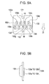
- Figs. 5A and 5B are diagrams for illustrating the circuit board 130.
- Fig. 5A shows the surface of the circuit board 130.
- Fig. 5B shows the circuit board 130, observed from the side.
- the surface of the circuit board 130 is a surface exposing to the outside when the circuit board 130 is mounted to the cartridge 10.
- the arrow Zt shown in Fig. 5A represents an inserting direction of the cartridge 10 to the holder 20.
- a boss notch 131 is formed in the upper end portion of the circuit board 130, and a boss hole 132 is formed at the lower end portion of the circuit board 130.
- the boss notch 131 and the boss hole 132 are used for easily mounting the circuit board 130 to the container body 100.
- the circuit board 130 has a terminal group 130t composed of nine terminals 130a to 130i disposed at the surface and a storage unit 133.
- the storage unit 133 disposed at the opposite surface stores information (for example, the remaining amount of ink or the ink color) about the ink of the cartridge 10.
- the terminals 130a to 130i have an approximately spherical shape and are arranged to form two rows which are approximately perpendicular to the inserting direction Zt. Among two rows, the row located at a rear side in the inserting direction Z, namely located at a lower side in Fig. 5A , is called a lower row (a first row), and the row located at a front side in the inserting direction Z, namely located at an upper side in Fig.
- an upper row is called an upper row (a second row).
- an appearance of the inclusive region 800 surrounded by a minimal convex polygon including the terminal group 130t is depicted with a dotted line.
- the inclusive region 800 is a hexagon.
- each terminal 130a to 130i includes a contact portion cp which respectively contacts a corresponding terminal of the device, mounted to the holder 20.
- Each contact portion cp of the terminals 130a to 130d of the upper row and each contact portion cp of the terminals 130e to 130i of the lower row are arranged to cross each other into a so-called zigzag pattern.
- the terminals 130a to 130d of the upper row and the terminals 130e to 130i of the lower row are arranged to cross each other into a zigzag pattern so that the center of the terminals is not in line with the inserting direction Zt.
- the circuit board 130 is mounted to the cartridge 10 so that as many terminals as close to the notch 140 of the cartridge 10 are included. In other words, the circuit board 130 is mounted to the cartridge 10 so that the lower row (the first row) is located lower than the upper row (the second row) in the height direction of the cartridge 10.
- the terminals 130a to 130d of the upper row and the terminals 130e to 130i of the lower row respectively have the following functions (usages).
- mounting detection terminals 130a, 130d, 130e and 130i are used for detecting whether the electric contact with a terminal of the device is acceptable, and they may also be called "contact detection terminals".
- Five other terminals 130b, 130c, 130f, 130g and 130h are terminals for the storage unit 133.
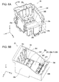
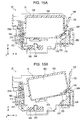
- Figs. 6A and 6B are diagrams for illustrating the holder 20.
- Fig. 6A is a first perspective view showing an appearance of the holder 20
- Fig. 6B is a second perspective view showing the appearance of the holder 20.
- the second perspective view does not show a part of the outer circumferential wall of the holder 20 for the convenience of description.
- Figs. 7A and 7B are diagrams for illustrating the detailed configuration of an opposite wall surface portion 25c.
- Fig. 7A is a view of the opposite wall surface portion 25c, observed in the X-axis positive direction.
- Fig. 7B is a partial enlarged view of Fig. 7A .
- Fig. 8 is a sectional view taken along the line VIII-VIII of Fig. 6A .
- the holder 20 has a concave shape in which a part of the holder 20 is opened so that the cartridge 10 may be attached or detached.
- the holder 20 includes a device-side bottom wall surface portion (also called a “bottom surface portion”) 25a, an engagement-side wall surface portion (a "front surface portion") 25b, an opposite wall surface portion (also called a “rear surface portion”) 25c, a first device-side side wall surface portion (also called a "left side surface portion”) 25e, and a second device-side side wall surface portion (also called a "right side surface portion”) 25f.
- a cartridge receiving chamber for receiving the cartridge 10 is formed.
- Each wall surface portion 25a, 25b, 25c, 25e and 25f is made of a synthetic resin such as polypropylene.
- the device-side bottom wall surface portion 25a configures a lower surface with respect to a usage posture of the printer 1.
- the opposite wall surface portion 25c, the engagement-side wall surface portion 25b, the first device-side side wall surface portion 25e and the second device-side side wall surface portion 25f stand from the device-side bottom wall surface portion 25a.
- the opposite wall surface portion 25c and the engagement-side wall surface portion 25b are opposite to the first device-side side wall surface portion 25e and the second device-side side wall surface portion 25f.
- the liquid supply tube 240 and the seal member 242 are mounted to the device-side bottom wall surface portion 25a.
- One end of the liquid supply tube 240 is connected to a print head 21 ( Fig. 8 ) mounted to the rear surface (the surface in the Z-axis negative direction) of the device-side bottom wall surface portion 25a.
- the other end of the liquid supply tube 240 is connected to the liquid supply hole 110 ( Fig. 3A ) of the cartridge 10.
- the seal member 242 is a member with elasticity such as a synthetic resin.
- the seal member 242 is disposed around the liquid supply tube 240 so as to prevent the ink from leaking out when the cartridge 10 is mounted to the holder 20.
- a porous metallic filter 240t partially contacting the foam 112 ( Fig. 4A ) in the liquid supply hole 110 is installed at the other end of the liquid supply tube 240.
- This filter 240t may employ for example a stainless steel mesh or a stainless steel non-woven fabric. In addition, the filter 240t may be excluded.
- FIG. 6B As shown in Fig. 6B , four through holes 290 (only three through holes are shown in the figure) and four first device-side regulating units 270 (only three first device-side regulating units are shown in the figure) are installed at the device-side bottom wall surface portion 25a in correspondence with the number (four) of the cartridges 10 mounted. Further, four contact mechanisms 280 (only three contact mechanisms are shown in the figure) are disposed at the device-side bottom wall surface portion 25a in correspondence with the number of the cartridges 10 mounted.
- the through holes 290 are used for detecting the remaining amount of ink in the cartridge 10 by using an optical detection device, described later, installed to the Z-axis negative direction side of the holder 20. Specifically, the through holes 290 allow the light emitting from the optical detection device to transmit therethrough and allow the light reflected by the cartridge 10 to transmit therethrough.
- the first device-side regulating unit 270 has a protrusion shape. In addition, the first device-side regulating unit 270 has a shape sharpened upwards.
- the notch 140 serving as the first regulating unit of the cartridge 10 is inserted into the first device-side regulating unit 270 to regulate the movement of the cartridge 10 in the width direction (the Y-axis direction).
- the first device-side regulating unit 270 is also called a regulation pin 270.
- the regulation pin 270 may be formed integrally with the holder 20 as in this embodiment or may be mounted to the device-side bottom wall surface portion 25a as a separate unit.
- the contact mechanism 280 is used for electrically connecting the control unit 60 of the printer 1 to the circuit board 130 of the cartridge 10.
- the contact mechanism 280 includes a plurality of electric contact members (also called “terminals") 280a to 280i for contacting the terminals 130a to 130i of the circuit board 130.
- the number of the electric contact members 280a to 280i corresponds to the number of the terminals 130a to 130i ( Fig. 5A ) of the circuit board 130, which is nine in this embodiment.
- the contact mechanisms 280 are electrically connected to the control unit 60.
- the holder 20 has a device-side engagement unit 260 disposed adjacent to the engagement-side wall surface portion 25b.
- the device-side engagement unit 260 is located at a predetermined height from the device-side bottom wall surface portion 25a.
- the device-side engagement unit 260 is engaged with the container-side regulating unit 124 ( Fig. 3B ) of the cartridge 10 in order to regulate the movement of the cartridge 10 in the height direction when the cartridge 10 is mounted.
- the opposite wall surface portion 25c includes a standing wall portion 216, a guide channel 200t, and a hole portion 202 formed in the standing wall portion 216.
- the standing wall portion 216 extends upwards (in the Z-axis positive direction) from the device-side bottom wall surface portion 25a.
- the standing wall portion 216 includes an opposite surface 216u, an extension surface 216t, and an upper surface 216s in the order from the below.
- the opposite surface 216u extends right upwards from the device-side bottom wall surface portion 25a.
- the opposite surface 216u forms a surface approximately parallel with the outer surface of the third wall surface portion 100c ( Fig. 3A ) of the cartridge 10 with respect to the mounted state where the cartridge 10 is mounted to the holder 20.
- a single hatching is given to the opposite surface 216u.
- the extension surface 216t extends out of the holder 20 from the upper end of the opposite surface 216u. In other words, with respect to the mounted state, the extension surface 216t extends in a direction away from the outer surface of the third wall surface portion 100c ( Fig. 3A ) of the cartridge 10. In this embodiment, the extension surface 216t configures a slanted surface which is slanted with respect to the vertical direction.
- the opposite wall surface portion 25c has a rotation point 216w corresponding to the rotation point 166w of the cartridge 10. The rotation point 216w is regulated by the border between the opposite surface 216u and the extension surface 216t. In other words, the rotation point 216w may be also called the upper end of the opposite surface 216u.
- the upper surface 216s extends upwards from the lower end of the extension surface 216t with respect to the usage posture of the printer 1.
- the upper surface 216s is also slanted with respect to the vertical direction, similar to the extension surface 216t.
- a space portion 216sp in which the cartridge 10 may be partially received when the cartridge 10 is turned and detached is formed.
- the protrusion unit 160 ( Fig. 3A ) of the cartridge 10 is inserted into the approximately spherical hole portion 202.
- the movement of the cartridge 10 in the width direction (the Y-axis direction) and the height direction (Z-axis direction) are regulated within a predetermined range.
- the width Wb of the hole portion 202 is approximately identical to the width Wt of the protrusion unit 160 of the cartridge 10.
- the gap of the protrusion unit 160 ( Fig. 3C ) of the cartridge 10 in the hole portion 202 of the holder 20 in the height direction is greater than the gap in the width direction.
- the guide channel 200t guides the protrusion unit 160 to the hole portion 202 while regulating the movement of the cartridge 10 in the width direction when the cartridge 10 is mounted to the holder 20.
- the guide channel 200t is formed from the upper end of the opposite wall surface portion 25c over the hole portion 202.
- a single hatching is given to the hole portion 202.
- the guide channel 200t there is no necessity to provide another embodiment such as a partition wall for positioning the cartridge 10 to the holder 20, and therefore the holder 20 may become smaller.
- the upper end of the guide channel 200t may not be located at the upper end of the opposite wall surface portion 25c but may be located in a middle of the opposite wall surface portion 25c in the height direction.
- the width Wa of the upper end 200ta of the guide channel 200t is greater than the width Wb of the lower end 200tb.
- the lower end 200tb has the same width as the hole portion 202.
- the width Wa of the upper end 200ta is greater than the width Wt ( Fig. 3C ) of the protrusion unit 160 of the cartridge 10.
- the width of the guide channel 200t is monotonously reduced as the lower end 200tb (namely, the hole portion 202) is approached from the upper end 200ta.
- the term "monotonous reduction" means that a region with a consistent width may be included if the width does not increase in any region from the upper end 200ta to the lower end 200tb.
- the guide channel 200t has a lower guide channel 200tu which is tapered to have a gradually decreasing width as being closer to the hole portion 202.
- a border between the lower guide channel 200tu and other parts is depicted with a broken line.
- the opposite wall surface portion 25c has a deformation unit 212 which may be elastically deformed in the depth direction (X-axis direction, a direction in which the opposite wall surface portion 25c is opposite to the device-side engagement unit 260) of the guide channel 200t.
- the deformation unit 212 is configured to be deformable toward the outside of the cartridge receiving chamber which receives the cartridge 10.
- the deformation unit 212 is formed by giving the notches 214 to both ends of a channel bottom wall surface portion 213 which configures the bottom surface of the guide channel 200t.
- the notch 214 is formed through the channel bottom wall surface portion 213.
- the deformation unit 212 grows over a predetermined height in a central portion of the channel bottom wall surface portion 213 from the region contacting the hole portion 202.
- the predetermined height represents a region higher than the intersection point where the channel bottom wall surface portion 213 intersects the trajectory of the rotating protrusion unit 160 ( Fig. 4A ) when the cartridge 10 is mounted in a predetermined method.
- the details will be described later.
- Figs. 9A and 9B are diagrams for illustrating a mounted state of the cartridge 10 to the holder 20.
- Fig. 9A is a first view showing that the cartridge 10 is mounted
- Fig. 9B is a second view showing that the cartridge 10 is mounted.
- Figs. 9A and 9B show a section of the cartridge 10 taken along the line IX-IX of Fig. 3B and a section of the holder 20 corresponding to the IX-IX section.
- a general mounting method (a normal mounting method) which is generally adopted when a user mounts the cartridge 10 to the holder 20 will be described.
- the cartridge 10 is mounted to the holder 20 by being slanted so that the protrusion unit 160 of the third wall surface portion 100c contacts the opposite wall surface portion 25c.
- the cartridge 10 is moved to a right lower position represented by the arrow Zw.
- the width Wa of the upper end of the guide channel 200t is greater than the width Wt of the protrusion unit 160 of the cartridge 10, the protrusion unit 160 may be easily inserted into the guide channel 200t.
- the deformation unit 212 is elastically deformed toward the outside (X-axis negative direction). As described above, as the deformation unit 212 is elastically deformed, the cartridge 10 may be smoothly mounted to the holder 20.
- Figs. 10A and 10B are second views for illustrating a mounted state of the cartridge to the holder.
- Fig. 10A shows a section of the cartridge 10 taken along the line XA-XA of Fig. 3B and a section of the holder 20 corresponding to the XA-XA section, similar to Figs. 9A and 9B .
- Fig. 10B is a perspective view showing the vicinity of the regulation pin 270 of Fig. 10A .
- the protrusion unit 160 is easily inserted into the hole portion 202 by the guidance of the guide channel 200t. In this state, the container-side regulating unit 124 of the cartridge 10 is not engaged with the device-side engagement unit 260 of the holder 20.
- the regulation pin 270 of the holder 20 is inserted into the notch 140 of the cartridge 10.
- the container-side regulating unit 124 is engaged with the device-side engagement unit 260.
- the cartridge 10 since the movement of the second wall surface portion 100b to which the circuit board 130 is mounted in the width direction is regulated, the cartridge 10 may be precisely positioned with respect to the holder 20.
- the possibility that a device-side terminal 280t (though nine terminals are present, it is just called the device-side terminal 280t for convenience) of the contact mechanism 280 does not contact each terminal 130a to 130i ( Figs. 5A and 5B ) of the circuit board 130 of the cartridge 10 may be decreased.
- the notch 140 is installed at a location closer to the first wall surface portion 100a rather than the circuit board 130, when the cartridge 10 is mounted to the holder 20, the regulation pin 270 is inserted into the notch 140 of the cartridge 10 before each terminal 130a to 130i of the circuit board 130 contacts the device-side terminal 280t of the contact mechanism 280.
- each terminal 130a to 130i of the circuit board 130 may contact the contact mechanism 280. Therefore, when the cartridge 10 is mounted to the holder 20, each terminal 130a to 130i may securely contact the contact mechanism 280.
- the protrusion unit 160 may be easily guided to the hole portion 202.
- the guide channel 200t has the lower guide channel 200tu, the protrusion unit 160 may be more smoothly guided to the hole portion 202.
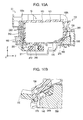
- Figs. 11A and 11B is a diagram for illustrating a state after the mounting.
- Fig. 11A shows a section of the cartridge 10 taken along the line XIA-XIA of Fig. 3B and a section of the holder 20 corresponding to the XIA-XIA section, similar to Figs. 9A and 9B .
- Fig. 11B is a perspective view showing the mounted state.
- the ink received in the liquid receiving chamber 180 is depicted with dots.
- the container-side regulating unit 124 is engaged with the device-side engagement unit 260 so that the movement of the cartridge 10 in the height direction is regulated.
- the rotation point 216w is located below an engagement point 1241.
- the lever 120 is engaged with the device-side engagement unit 260 in a state of being closer to the second wall surface portion 100b rather than a non-loaded state. Therefore, the movement of the cartridge 10 in the length direction (the X-axis direction) is regulated as the lever 120 presses the container body 100 to the opposite wall surface portion 25c.
- the liquid supply tube 240 is connected to the liquid supply hole 110.
- each terminal of the circuit board 130 contacts each corresponding electric contact member 260a to 280i of the contact mechanism 280 to transmit various kinds of information such as the ink color and the remaining amount of ink between the cartridge 10 and the control unit 60 ( Fig. 1 ) of the printer 1. Further, a remaining amount of ink is detected at a predetermined timing by using the optical detection device 90.
- the ink is supplied to the print head 21 via the liquid supply hole 110 and the liquid supply tube 240 by the suction of the print head 21.
- the movement of the cartridge 10 is generally regulated by the hole portion 202 of the holder 20, the device-side engagement unit 260 and the regulation pin 270.
- the hole portion 202 and the protrusion unit 160 cooperate to regulate the movement in the width direction (the Y-axis direction) and the height direction (the Z-axis direction) of the third wall surface portion 100c
- the device-side engagement unit 260 and the container-side regulating unit 124 cooperates to regulate the movement in the height direction of the second wall surface portion 100b
- the regulation pin 270 and the notch 140 cooperate to regulate the movement in the width direction of the second wall surface portion 100b.
- the holder 20 and the cartridge 10 move in the main scanning direction (the Y-axis direction, or the width direction of the cartridge 10).
- the cartridge 10 receives an external force (an inertial force) in the width direction.
- the cartridge 10 rotates in a rotation direction with a width directional component centered around the liquid supply hole 110 ( Fig. 11A ).
- the second wall surface portion 100b rotates in the direction of the arrow YR1
- the third wall surface portion 100c rotates in the direction of the arrow YR2.
- the circuit board 130 is installed to the second wall surface portion 100b.
- the movement (distortion) of the circuit board 130 with respect to the holder 20 may be suppressed rather than by providing the notch 140 to the first wall surface portion 100a.
- the electric connection between the circuit board 130 (in detail, the terminal group 130t) and the printer 1 may be maintained in a good state after the mounting.
- the circuit board 130 is disposed to partially overlap with the notch 140 in the length direction ( Fig. 3A ). Therefore, the movement (misalignment) of the circuit board 130 (in detail, the terminal group 130t) with respect to the holder 20 may be suppressed to the minimum.
- the notch 140 is more preferably installed to overlap with a part of the terminal group 130t of the circuit board 130 with respect to the length direction (the X-axis direction). By doing so, the movement (misalignment) of the terminal group 130t with respect to the holder 20 may be further suppressed to the minimum.
- a member for forming (defining) the channel is required peripherally.
- the notch 140 for regulating the movement in the width direction is provided to the second wall surface portion 100b so that the size of the cartridge in the length direction (the X-axis direction) may be reduced.
- the notch 140 may suppress the movement of the prism 170 in the width direction by cooperating with the regulation pin 270.
- the prism 170 is disposed in contact with the inner surface of the second wall surface portion 100b having the notch 140 ( Fig. 4A ).
- the movement (misalignment) of the prism 170 in the width direction may be suppressed to the minimum so that the remaining amount of ink may be detected with good precision.
- the possibility that the flow of the ink flowing toward the liquid supply hole 110 is blocked by the prism 170 may be decreased. By doing so, the ink in the liquid receiving chamber 180 may be consumed efficiently, which may reduce the remaining amount of ink.
- the notch 140 as the first regulating unit, when the cartridge 10 is attached to or detached from the holder 20, the possibility that the first regulating unit (the notch 140) interferes the holder 20 may be decreased, rather than the case where the first regulating unit has a protrusive shape (in this case, the first device-side regulating unit 270 has a concave state). By doing so, the occurrence of any inconvenience such as the breakdown of the cartridge 10 or the holder 20 may be suppressed.
- the cartridge 10 since the cartridge 10 has the notch 140 for regulating the movement in the width direction at the second wall surface portion 100b to which the circuit board 130 is mounted, a misalignment of the circuit board 130 to the holder 20 may be suppressed. Therefore, the possibility that the electric connection between the circuit board 130 and the printer 1 is blocked may be decreased. In addition, since the misalignment of the circuit board 130 to the holder 20 may be suppressed, many terminals may be provided by the circuit board 130. By doing so, it becomes possible to transmit more information between the circuit board 130 and the printer 1.
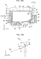
- Figs. 12A and 12B are diagrams for illustrating a detached state of the cartridge 10 from the holder 20.
- Fig. 12A is a first view showing a detaching posture
- Fig. 12B is a view for illustrating one of the effects of this embodiment.
- Fig. 12A shows a section of the cartridge 10 taken along the line XIIA-XIIA of Fig. 3B and a section of the holder 20 corresponding to the XIIA-XIIA section.
- the engagement releasing unit 122 is elastically deformed in an approaching (pressing) direction (the X-axis negative direction) toward the container body 100 (in detail, the second wall surface portion 100b). Then, the engagement of the device-side engagement unit 260 and the container-side regulating unit 124 is released.
- the engagement releasing unit 122 is formed so that the second side surface 122u is slanted a predetermined angle ⁇ from the vertical direction, in a case where the first side surface 122t contacts the second wall surface portion 100b.
- the engagement releasing unit 122 By forming the engagement releasing unit 122 as described above, if an external force F is added to the engagement releasing unit 122 in the X-axis negative direction, the engagement may be released and at the same time the cartridge 10 may be detached from the holder 20 efficiently. The reason will be described with reference to Fig. 12B .
- the case where an external force F is added to the engagement releasing unit 122 in the approaching direction (the X-axis negative direction) in which the engagement releasing unit 122 approaches the container body 100 (in detail, the second wall surface portion 100b) is considered.
- the external force F may be decomposed into a force F1 of a tangential component of a circumference based on the rotation point 216w and a radial component F2. If the second side surface 122u is slanted (slanted downwards) to be closer to the rotation point 216w from the upper end to the lower end, the force F1 of the tangential component may be efficiently transferred to the engagement releasing unit 122.
- the engagement may be released and the cartridge 10 may be easily rotated in a direction (the arrow Rd) in which the cartridge 10 is detached.
- Figs. 13A and 13B are second views for illustrating a posture of detaching the cartridge 10 from the holder 20.
- Fig. 13A is a view showing that the cartridge 10 rotates centered around the rotation point 216w.
- Fig. 13B is a second view showing that the cartridge 10 rotates centered around the rotation point 216w.
- Figs. 13A and 13B show a section of the cartridge 10 taken along the line XIII-XIII of Fig. 3B and a section of the holder 20 corresponding to the XIII-XIII section.
- the third wall surface portion 100c of the cartridge 10 contacts the upper surface 216s.
- the rotation in the predetermined direction is interfered since the upper surface 216s becomes a barrier.
- a user may easily grip and handle the second wall surface portion 100b of the cartridge 10 so that the second wall surface portion 100b may be lifted up in the vertical direction with respect to the holder 20.
- the cartridge 10 is configured so that the rotation point 166w is located below the engagement point 124t and the engagement releasing unit 122 is located above the engagement point 124t ( Fig. 11A ). Therefore, as shown in Fig. 12A , by applying an external force in a predetermined direction (the X-axis negative direction) to the engagement releasing unit 122, the cartridge 10 may be easily detached from the holder 20 at the rotation point 216w.
- the manipulation for releasing the engagement of the container-side regulating unit 124 and the device-side engagement unit 260 and the manipulation for detaching the cartridge 10 from the holder 20 may be performed in series ( Figs. 12A to 13B ).
- the rotation point 216w of the holder 20 may be easily defined by the opposite surface 216u and the extension surface 216t of the opposite wall surface portion 25c.
- Figs. 14A to 14C are diagrams for illustrating various mounting methods. Figs. 14A to 14C are depicted in time series. In addition, Figs. 14A to 14C show a section of the cartridge 10 taken along the line XIV-XIV of Fig. 3B and a section of the holder 20 corresponding to the XIV-XIV section. With reference to Figs. 14A to 14C , a mounting method (an engagement mounting method) for slanting the cartridge 10 so that the second wall surface portion 100b is located right below the third wall surface portion 100c and therefore being inserted into the holder 20 will be described.
- an engagement mounting method for slanting the cartridge 10 so that the second wall surface portion 100b is located right below the third wall surface portion 100c and therefore being inserted into the holder 20
- the container-side regulating unit 124 is engaged with the device-side engagement unit 260.
- the cartridge 10 is mounted to the holder 20 by rotating the cartridge 10 centered around the engagement point 124t as the rotation point.
- the protrusion unit 160 moves along a rotating trajectory Rm.
- This rotating trajectory Rm intersects the deformation unit 212.
- the deformation unit 212 is located at the point where the rotating trajectory Rm intersects the holder 20.
- the deformation unit 212 is formed at the center of the channel bottom wall surface portion 213 to reach a location higher than the cross point Rx where the rotating trajectory Rm intersects the channel bottom wall surface portion 213.
- the protrusion unit 160 contacts the deformation unit 212.
- the deformation unit 212 is pushed in the outer direction (the X-axis negative direction) of the holder 20 by the protrusion unit 160 and is elastically deformed. As the deformation unit 212 is elastically deformed, the third wall surface portion 100c may be pushed downwards in the vertical direction without restricting the movement of the cartridge 10. By doing so, as shown in Fig. 14C , the cartridge 10 may be mounted to the holder 20.
- Figs. 15A and 15B are diagrams for illustrating various mounting methods.
- Fig. 15A is a first view for illustrating a mounting method to the holder 20.
- Fig. 15B is a second view for illustrating the mounting method to the holder 20.
- Figs. 15A and 15B show a section of the cartridge 10 taken along the line XV-XV of Fig. 3B and a section of the holder 20 corresponding to the XV-XV section.
- Fig. 15A shows a mounting method (an upper side access mounting method) for mounting the cartridge 10 to the holder 20 from a location just above the holder 20 without slanting the cartridge 10. Even in this mounting method, since the deformation unit 212 may be elastically deformed, the cartridge 10 may be mounted to the holder 20 without restricting the movement of the cartridge 10.
- Fig. 15B shows a mounting device (a front access mounting method) for mounting the cartridge 10 to the holder 20 without inserting the protrusion unit 160 to the guide channel 200t.
- a mounting device a front access mounting method
- the possibility that the movement of the cartridge 10 is restricted so that the cartridge 10 may not be mounted to the holder 20 may be decreased. Therefore, a method for preventing the mounting in a specific mounting method (a mounting method in which the movement is restricted or the like) may not be provided to the passage of the holder 20. Therefore, the cartridge 10 may also be mounted to the holder 20 according to the front access mounting method.
- the holder 20 has the deformation unit 212, before the cartridge 10 is mounted to the holder 20, the possibility that the movement of the cartridge 10 is restricted in the holder 20 may be decreased. By doing so, it is not necessary to provide a mechanism for prohibiting a specific mounting method to the passage of the holder 20, and therefore the manipulation when mounting the cartridge 10 to the holder 20 may be improved while decreasing the number of parts of the holder 20. In other words, a user may mount the cartridge 10 to the holder 20 using various mounting methods without being limited to any specific mounting method.
- Figs. 16A and 16B are diagrams for illustrating a cartridge 10a of a second embodiment.
- Fig. 16A is a sectional of the cartridge 10a, which corresponds to the XVIA-XVIA section of Fig. 3B .
- Fig. 16B is a view for illustrating prisms 170a to 170c of the cartridge 10a.
- the prisms 170a to 170c are different from those of the first embodiment, and other configurations are identical to those of the first embodiment, so the same reference numeral is given to the same component and is not described in detail here.
- the configuration of the holder 20 to which the cartridge 10a is mounted and the configuration of the printer 1 are identical to those of the first embodiment.
- each prism 170a to 170c includes a portion with a right isosceles triangular prism shape which includes the reflective surface 170f.
- the prisms 170a to 170c are disposed to have different distances between the reflective surfaces and the first wall surface portion 100a. In detail, the prism closer to the notch 140 is disposed to have a longer distance from the first wall surface portion 100a.
- the first prism 170a with a greatest height is disposed to contact the inner surface of the second wall surface portion 100b to which the notch 140 is installed.
- the prism is disposed at a location away from the second wall surface portion 100b.
- the number of optical detection devices corresponding to the number of prisms may be disposed to the printer 1 to detect a remaining amount of ink, and a single optical detection device may be moved just below the prisms 170a to 170c to detect a remaining amount of ink.
- the remaining amount of ink of the cartridge 10a may be detected in more detail.
- the distance between the optical detection device and the reflective surface 170f is increased, the difference in relative locations of the reflective surface 170f and the optical detection device is increased so that the detection precision of the remaining amount of ink tends to be deteriorated.
- the prism 170a is disposed closer to the notch 140 as much so that the distortion with respect to the holder 20 may be suppressed.
- the difference in detection precision on the remaining amount of ink using the prisms 170a to 170c may be decreased.
- the cartridge 10a of the second embodiment has the notch 140 as in the first embodiment, the movement in the width direction (the Y-axis direction) may be regulated in cooperation with the regulation pin 270 of the holder 20. Therefore, the electric connection of the circuit board 130 (in detail, the terminal group 130t) and the printer 1 may be maintained in a good state.
- Figs. 17A to 17E are diagrams for illustrating modified examples of the first modified example.
- Figs. 17A to 17E are diagrams showing the vicinity of the prism 170.
- the prism 170 is disposed away from the inner surface of the first vertical wall portion 100b1, and protrusive members 175a to 175e are installed between the prism 170 and the first vertical wall portion 100b1, different from the first embodiment.
- Other configurations are identical to those of the first embodiment, and the same configuration is represented with the same reference numeral and is not described in detail here.
- the protrusive members 175a to 175e are protrusions extending from the first wall surface portion 100a into the liquid receiving chamber 180.
- the protrusive member may have a rectangular parallelepiped shape (175a, Fig. 17A ), a triangular prism shape (175b to 175e, Figs. 17B to 17E ), or the like.
- the protrusive members 175a, 175b and 175e are disposed to contact both of the prism 170 and the first vertical wall portion 100b1.
- the protrusive members 175a to 175e as described above, it is possible to prevent the ink from being blocked by the prism 170 so that the ink at the first vertical wall portion 100b1 is guided to the liquid supply hole 110 ( Fig. 4A ). Therefore, the ink in the liquid receiving chamber 180 ( Fig. 4A ) may be efficiently consumed.
- the cartridge 10 has the prism 170, 170a to 170c in order to detect a remaining amount of ink in the above embodiments ( Figs. 4A and 16A ), the prisms may be excluded.
- a sensor using a piezoelectric element or a sensor using an electrode may be adopted to detect a remaining amount of ink.
- the movement (misalignment) of the circuit board 130 with respect to the holder 20 may be suppressed, similar to the above embodiments, as the notch 140 of the cartridge 10 and the regulation pin 270 of the holder 20 cooperate.
- the manipulation for attaching or detaching the cartridge 10 to/from the holder 20 may be improved by means of the rotation point 166w, 216w or the deformation unit 212 of the holder 20.
- the cartridge 10 uses the notch 140 as the first regulating unit in the above embodiments, the shape is not limited thereto.
- a protrusion may be installed to the second wall surface portion 100b as the first regulating unit.
- a concave portion in which the protrusion is inserted instead of the regulation pin 270 is provided to the holder 20.
- the notch 140 is installed at the approximate center of the first vertical wall portion 100b1 in the width direction ( Fig. 3B ), the invention is not limited thereto.
- the notch 140 may be formed at a corner of the first vertical wall portion 100b1 in the width direction.
- both sides of the notch 140 of the above embodiments in the width direction are formed by the first vertical wall portion 100b1, it is also possible that only one side is formed by the first vertical wall portion 100b1 so that the other side is opened.
- the movement of the cartridge 10 in the width direction (the movement in the width direction toward any one side thereof) may be regulated so that the misalignment of the circuit board 130 and the holder 20 may be suppressed.
- the manipulation for attaching or detaching the cartridge 10 to/from the holder 20 may be improved by the rotation point 166w, 216w or the deformation unit 212 of the holder 20.
- the cartridge 10 may have any shape.
- the cartridge 10 may have an approximately rectangular parallelepiped shape without the slanted wall portion 100b2, or the second wall surface portion 100b may have a slanted shape as a whole.
- each wall surface portion 100a to 100f may be slanted at a certain angle, and an intersecting angle of the wall surface portions 100a to 100f may be other than 90 degrees.
- the ink cartridge 10 may have any shape if the liquid receiving chamber 180 for receiving an ink may be formed therein.
- a protrusion may be provided to the third wall surface portion 100c so that the protrusion is set to the rotation point 166w. Even in this configuration, the cartridge 10 may be easily detached from the holder 20 by rotating the cartridge 10 centered around the rotation point 166w.
- the protrusion unit may be excluded.
- the guide channel 200t or the hole portion 202 may also be excluded with respect to the holder 20 correspondingly. Even in this configuration, the manipulation for attaching or detaching the cartridge 10 to/from the holder 20 may be improved by the rotation point 166w, 216w or the deformation unit 212 of the holder 20, similar to the above embodiments.
- the guide channel 200t of the holder 20 has the tapered lower guide channel 200tu in the above embodiments, the invention is not limited thereto.
- the guide channel 200t may have an approximately uniform width. Even in this configuration, the protrusion unit 160 may be easily guided to the hole portion 202 of the holder 20 by the guide channel 200t.
- the terminals of the circuit board 130 are configured in two rows in the above embodiments, the terminals may also be configured in one row or in three or more rows.
- the first row closest to the first regulating unit (notch) 140 preferably include more terminals than the second row farthest from the first regulating unit (notch) 140. By doing so, the electric connection between the printer 1 and each terminal included in the first and second rows may be maintained in a good state.
- the terminals are configured in three or more rows, more preferably the closer the row is to the first regulating unit (notch) 140 the more terminals are included. By doing so, the electric connection between the printer 1 and each terminal of the circuit board 130 may be maintained in a good state.
- the elastic portion (lever) 120 is provided to the second wall surface portion 100b of the cartridge 10 in the above embodiments, it is also possible that the container-side regulating unit 124 is formed at the second wall surface portion 100b of the cartridge 10 and also the engagement releasing unit 122 is provided to the holder 20. Even in this configuration, the engagement of the holder 20 and the container-side regulating unit 124 may be released by applying an external force to the engagement releasing unit 122 by a user.
- the terminal group 130t may be directly provided to the container body 100. Even in this configuration, the movement (misalignment) of the terminal group 130t with respect to the liquid ejecting device (the printer 1) is suppressed so that the contact between the terminal group 130t and the liquid ejecting apparatus (the printer 1) may be maintained in a good state.
- the notch 140 is more preferably installed to the container body 100 to overlap with a part of the terminal group 130t. By doing so, the movement (misalignment) of the terminal group 130t to the liquid ejecting device (the printer 1) may be further suppressed.
- the invention may be applied to a liquid housing container capable of supplying a liquid to for example a device having a colored material ejecting head such as a liquid crystal display, a device having an electrode material (conductive paste) ejecting head used for forming an electrode of an organic EL display, a surface light-emitting display (FED) or the like, a device having a bio-organic material ejecting head used for producing a bio chip, a device having a test piece ejecting head as a precise pipette, and a liquid ejecting device such as a printing device or a micro dispenser without being limited thereto.
- a liquid housing container capable of supplying a liquid to for example a device having a colored material ejecting head such as a liquid crystal display, a device having an electrode material (conductive paste) ejecting head used for forming an electrode of an organic EL display, a surface light-emitting display (FED) or the like, a device having a bio-organic
- the invention may be applied to a holder to which various kinds of liquid housing containers may be detachably mounted.
- liquids coloring agents, conductive paste, bio organic material, or the like
- the invention may be applied even to various liquid ejecting devices equipped with a holder and a liquid ejecting system having a liquid housing container corresponding to various liquid ejecting devices.
Landscapes
- Ink Jet (AREA)
- Containers And Packaging Bodies Having A Special Means To Remove Contents (AREA)
Abstract
Description
- The present invention relates to a holder having a detachable liquid housing container, and a liquid housing container.
- A printer which is one example of a liquid ejecting apparatus ejects an ink from a print head to a subject to be printed (for example, printing paper) and performs printing. The technique of using an ink cartridge containing an ink therein is known as an ink supplying technique for the print head (for example,
JP-A-2006-142483 - The holder may be formed to be detachable from the ink cartridge so that a user may exchange the ink cartridge when the amount of ink is deficient in the ink cartridge.
-
JP-A-2007-230248 JP-A-2010-23458 - However, there is still scope for improvement of the manipulation when the ink cartridge is attached to or detached from the holder. For example, a user may find it troublesome when manipulating to detach the ink cartridge from the holder. In particular, in a case where the ink cartridge engages with the holder, it is required to release the engagement so that the ink cartridge is detached from the holder, but a user may find it troublesome in this manipulation.
- In addition, when the ink cartridge is attached to the holder, according to the installation order, a part of the ink cartridge may contact the inner wall surface of the holder before the ink cartridge is mounted, which may disturb the insertion of the ink cartridge.
- In addition, in order to improve the manipulation, it is possible to divide the holder and provide a wall therebetween. In this case, there may be a problem in that the size of the holder may increase.
- The manipulation of attachment/detachment as described above is a common issue of a liquid housing container which is detachably mounted to a liquid ejecting apparatus and a holder to which the liquid housing container may be detachably mounted, without being limited to an ink cartridge and a holder to which the ink cartridge may be detachably mounted.
- An advantage of some aspects of the invention is to provide a holder to which the liquid housing container may be detachably mounted, which has an improved manipulation in attaching or detaching the liquid housing container. In addition, another advantage of some aspects of the invention is to provide a liquid housing container detachably mounted to the holder, which has an improved manipulation for attachment to and detachment from the holder.
- The invention is directed to solve at least a part of the above problems and it may be implemented as the following aspects and applications.
- A holder is provided to a liquid ejecting device having a head for ejecting a liquid and a liquid housing container capable of storing a liquid to be supplied to the head is attachable to or detachable from the holder, wherein the holder has a rotation point for rotating the mounted liquid housing container in a predetermined direction so as to be detached from the holder.
- According to the holder of Application 1, since the holder has the rotation point for detaching the liquid housing container, a user may easily detach the liquid housing container from the holder by rotating the liquid housing container.
- The holder according to Application 1 further includes a device-side bottom wall surface portion which forms a bottom surface; a device-side engagement unit engaged with the liquid housing container to regulate movement of the liquid housing container; and an opposite wall surface portion installed to stand from the device-side bottom wall surface portion and located to face the device-side engagement unit while the device-side bottom wall surface portion is interposed therebetween, wherein the rotation point is formed at the opposite wall surface portion so that the liquid housing container rotates in the predetermined direction centered around the rotation point by adding a force to the liquid housing container in a direction in which the engagement is released.
- According to the holder of Application 2, the manipulation for releasing the engagement of the holder and the liquid housing container and the manipulation for detaching the liquid housing container from the holder may be performed in series. By doing so, the manipulation when the liquid housing container is detached from the holder may be improved.
- In the holder according to Application 2, the liquid housing container attached to or detached from the holder includes a container body having a first wall surface portion which becomes a bottom surface when the liquid housing container is mounted to the holder, a second wall surface portion connected to the first wall surface portion, and a third wall surface portion connected to the first wall surface portion and facing the second wall surface portion, wherein, with respect to a usage posture of the liquid ejecting device, the opposite wall surface portion includes: an opposite surface extending upwards from the device-side bottom wall surface portion, the opposite surface being approximately parallel with an outer surface of the third wall surface portion when the liquid housing container is mounted; and an extension surface which extends from an upper end of the opposite surface in a direction away from the outer surface of the third wall surface portion, wherein the rotation point is defined by a border of the opposite surface and the extension surface.
- According to the holder of Application 3, the rotation point may be easily formed using the opposite wall surface portion of the holder.
- In the holder according to Application 2, the liquid housing container attached to or detached from the holder includes a container body having a first wall surface portion which becomes a bottom surface when the liquid housing container is mounted to the holder, a second wall surface portion connected to the first wall surface portion, and a third wall surface portion connected to the first wall surface portion and facing the second wall surface portion, wherein, with respect to a usage posture of the liquid ejecting device, the opposite wall surface portion includes an opposite surface which extends upward from the device-side bottom wall surface portion and which is approximately parallel with an outer surface of the third wall surface portion when the liquid housing container is mounted, and wherein a space portion is formed above the opposite surface to receive a part of the liquid housing container so that the liquid housing container is allowed to rotate.
- According to the holder of Application 4, the rotation point may be easily formed by means of the space portion and the opposite surface which is one surface of the opposite wall surface portion.
- In the holder according to any one of Applications 2 to 4, with respect to a usage posture of the liquid ejecting device, the rotation point is located below an engagement point where the liquid housing container is engaged with the device-side engagement unit.
- According to the holder of Application 5, by adding an external force in a predetermined direction to a region located above the engagement point of the liquid housing container, the engagement of the holder and the liquid housing container may be released, and the liquid housing container may be rotated and detached from the holder. By doing so, the manipulation when the liquid housing container is detached from the holder may be further improved.
- In the holder according to any one of Applications 2 to 5, the opposite wall surface portion has a hole portion located closer to the device-side bottom wall surface portion than the rotation point so that a protrusion unit provided to the liquid housing container is inserted thereto to regulate movement of the liquid housing container after being mounted.
- According to the holder of Application 6, the movement of the liquid housing container may be regulated by the hole portion after the liquid housing container is mounted, and the protrusion unit of the liquid housing container may be pulled out from the hole portion by rotating the liquid housing container in order to detach the liquid housing container.
- In the holder according to Application 6, the opposite wall surface portion has a guide channel for guiding the protrusion unit to the hole portion while regulating the movement of the liquid housing container in a width direction by the protrusion unit, when the liquid housing container is mounted.
- According to the holder of Application 7, in a case where the liquid housing container is mounted to the holder, a user may easily guide the protrusion unit of the liquid housing container to the hole portion of the holder by inserting the protrusion unit of the liquid housing container into the guide channel. Therefore, the manipulation when the liquid housing container is mounted to the holder may be improved.
- In the holder according to Application 7, with respect to a usage posture of the liquid ejecting device, the guide channel is formed over the hole portion from an upper end of the opposite wall surface portion.
- According to the holder of Application 8, since the upper end of the guide channel is located at the upper end of the opposite wall surface portion, a user may easily insert the protrusion unit of the liquid housing container into the guide channel.
- In the holder according to Application 7 or 8, with respect to a usage posture of the liquid ejecting device, the width of the upper end of the guide channel is greater than a width of the lower end of the guide channel.
- According to the holder of Application 9, since the upper end of the guide channel has a greater width, a user may more easily insert the protrusion unit of the liquid housing container into the guide channel.
- In the holder according to any one of Applications 7 to 9, the width of the guide channel monotonously decreases as the hole portion gets closer.
- According to the holder of
Application 10, a user may easily insert the protrusion unit of the liquid housing container into the guide channel and may accurately guide the protrusion unit toward the hole portion. - In the holder according to any one of Applications 7 to 10, the guide channel has a lower guide channel having a tapered shape whose width gradually decreases as the hole portion gets closer.
- According to the holder of Application 11, a user may smoothly guide the protrusion unit of the liquid housing container to the hole portion by means of the lower guide channel.
- In the holder according to any one of Applications 7 to 11, with respect to a usage posture of the liquid ejecting device, the lower end of the guide channel has the same width as the width of the hole portion.
- According to the holder of Application 12, the protrusion unit of the liquid housing container may be more smoothly guided from the guide channel to the hole portion.
- In the holder according to any one of Applications 7 to 12, a channel bottom wall surface portion which forms a bottom surface of the guide channel and is opposite to the liquid housing container has a deformation unit which is elastically deformable in the depth direction of the guide channel, and with respect to a usage posture of the liquid ejecting device, the lower end of the deformation unit may reach the hole portion.
- According to the holder of Application 13, as the deformation unit is provided, before the liquid housing container is mounted to the holder, the possibility that the movement of the liquid housing container in the holder is restricted may be decreased.
- In the holder according to Application 13, with respect to a usage posture of the liquid ejecting device, among the region of the channel bottom wall surface portion, the upper end of the deformation unit reaches a location higher than an intersection point where the channel bottom wall surface portion intersects a trajectory along which the protrusion unit rotates centered around an engagement point where the liquid housing container is engaged, before the protrusion unit of the liquid housing container is inserted into the hole portion, in a case where a container-side regulating unit of the liquid housing container which is to be engaged with the device-side engagement unit is engaged with the device-side engagement unit.
- According to the holder of Application 14, before the protrusion unit is inserted into the hole portion, even when the container-side regulating unit of the liquid housing container is engaged with the device-side engagement unit, the possibility that the movement of the liquid housing container is restricted in the holder may be decreased.
- In the holder according to Application 13 or 14, the deformation unit is obtained by forming notches at both ends of the channel bottom wall surface portion.
- According to the holder of Application 15, the deformation unit may be formed with a simple configuration by forming notches at both ends of the channel bottom wall surface portion.
- In the holder according to any one of Application 2 to 15, the device-side bottom wall surface portion includes a first device-side regulating unit which regulates the movement of the liquid housing container at least in a width direction by cooperating with a first regulating unit of the liquid housing container.
- According to the holder of Application 16, the movement of the liquid housing container after being mounted may be suppressed.
- In the holder according to Application 16, the first device-side regulating unit has a protrusive shape into which the first regulating unit which is a notch is inserted.
- According to the holder of Application 17, since the notch for regulating the movement in the width direction is installed to the liquid housing container which moves with respect to the holder when being mounted, the possibility that the mounting operation of the liquid housing container is restricted may be decreased rather than the case where the protrusion unit is installed instead of the notch.
- A liquid ejecting device has the holder according to any one of Applications 1 to 17.
- According to the liquid ejecting device of Application 18, it is possible to provide a liquid ejecting device equipped with the holder with an improved manipulation when the liquid housing container is attached or detached.
- A liquid housing container is attachable to and detachable from a liquid ejecting device having a head for ejecting a liquid, the liquid housing container including: a container body which forms a liquid receiving chamber for receiving a liquid therein and includes a first wall surface portion which becomes a bottom surface when the liquid ejecting device is mounted to a holder, a second wall surface portion connected to the first wall surface portion, and a third wall surface portion connected to the first wall surface portion to face the second wall surface portion; and an elastic portion having one end mounted to the second wall surface portion and having elasticity, the elastic portion being used for attachment to or detachment from the holder, wherein the elastic portion includes: a container-side regulating unit engaged with the holder to regulate the movement of the liquid housing container; and an engagement releasing unit provided above the container-side regulating unit and elastically deformed by an external force added thereto in a direction of pressing against the second wall surface portion to release the engagement, the engagement releasing unit allowing the liquid housing container to be detached from the holder by rotating the liquid housing container centered around a rotation point which is a contact portion of the third wall surface portion and the holder located below the engagement point.
- According to the liquid housing container of the Application 19, the liquid housing container may be rotated to release the engagement of the liquid housing container by the engagement releasing unit and to detach the liquid housing container from the holder.
- In the liquid housing container according to Application 19, the engagement releasing unit includes a first side surface opposite to the second wall surface portion and a second side surface opposite to the first side surface, and, in a case where the first side surface contacts the second wall surface portion, the second side surface is formed to be closer to the rotation point from the upper end to the lower end with respect to the direction in which the second and third wall surface portions are opposite.
- According to the liquid housing container of
Application 20, the second side surface is formed to be closer to the rotation point from the upper end to the lower end. Therefore, by applying an external force to the engagement releasing unit in the direction approaching the second wall surface portion (the length direction of the liquid housing container), the force in the rotation direction for rotating and detaching the liquid housing container may be efficiently transferred to the engagement releasing unit. By doing so, the liquid housing container may be rotated by the operation for releasing the engagement so that the liquid housing container may be easily detached from the holder. - Further, the invention may be implemented in various ways, and in addition to the liquid ejecting device equipped with the holder and the liquid housing container, the invention may be implemented as a method for manufacturing the holder having the above distinctive configuration and a method for manufacturing the liquid housing container having the above distinctive configuration.
- The invention will be described with reference to the accompanying drawings, wherein like numbers reference like elements.
-
Fig. 1 is a schematic diagram showing a liquid ejecting apparatus. -
Fig. 2 is a perspective view showing an appearance of a holder to which a cartridge is mounted. -
Figs. 3A to 3D are first diagrams for illustrating the cartridge. -
Figs. 4A to 4C are second diagrams for illustrating the cartridge. -
Figs. 5A and 5B are diagrams for illustrating a circuit board. -
Figs. 6A and 6B are diagrams for illustrating a holder. -
Figs. 7A and 7B are diagrams for illustrating a detailed configuration of an opposite wall surface portion. -
Fig. 8 is a sectional view taken along the line VIII-VIII ofFig. 6A . -
Figs. 9A and 9B are diagrams for illustrating a mounted state of the cartridge. -
Figs. 10A and 10B are second diagrams for illustrating a mounted state of the cartridge. -
Figs. 11A and 11B are diagrams for illustrating the state after the mounting. -
Figs. 12A and 12B are diagrams for illustrating a detached state of the cartridge. -
Figs. 13A and 13B are second diagrams for illustrating a detached state of the cartridge. -
Figs. 14A to 14C are diagrams for illustrating a mounting manner in a separate method. -
Figs. 15A and 15B are diagrams for illustrating a mounting manner in a separate method. -
Figs. 16A and 16B are diagrams for illustrating a cartridge of a second embodiment. -
Figs. 17A to 17E are diagrams for illustrating modified shapes of the first modified example. - Next, embodiments of the invention will be described in the following order.
- A. First Embodiment
- B. Second Embodiment
- C. Modified Example
-
Fig. 1 is a schematic diagram showing a liquid ejecting apparatus 1 having aliquid housing container 10 and aholder 20 as a first embodiment of the invention. The liquid ejecting apparatus 1 is an ink-jet printer 1 (hereinafter, referred to as just a "printer 1") which ejects an ink to a printing paper PA to perform printing. The printer 1 includes anink cartridge 10 serving as a liquid housing container, aholder 20, afirst motor 52, asecond motor 50, acontrol unit 60, amanipulation unit 70, apredetermined interface 72, and anoptical detection device 90. In addition, hereinafter, theink cartridge 10 is simply called a "cartridge 10". - The
holder 20 has a print head (not shown) for ejecting an ink to the printing paper PA and its opposite side. In addition, thecartridge 10 is detachably loaded to theholder 20. In eachcartridge 10, an ink of cyan, magenta, yellow or the like is received, respectively. The ink received in thecartridge 10 is supplied to the print head of theholder 20 so that the ink is ejected to the printing paper PA. - The
first motor 52 drives theholder 20 in a main scanning direction. Thesecond motor 50 feeds the printing paper PA in a sub-scanning direction. Thecontrol unit 60 controls overall operations of the printer 1. - The
optical detection device 90 is fixed at a predetermined location. When theholder 20 is moved to a predetermined location, theoptical detection device 90 irradiates light toward thecartridge 10 in order to detect the remaining amount of the ink. In addition, the details will be described later. - The
control unit 60 controls thefirst motor 52, thesecond motor 50 and the print head based on printing data received from acomputer 80 or the like connected thereto via thepredetermined interface 72 to perform printing. Thecontrol unit 60 is connected to themanipulation unit 70 to receive various manipulations from a user. -
Fig. 2 is a perspective view showing an appearance of theholder 20 to which thecartridge 10 is mounted. For ease of description,Fig. 2 shows that onecartridge 10 is mounted to theholder 20. In addition, in order to specify directions, X, Y and Z axes orthogonal to each other are depicted inFig. 2 . The X, Y and Z axes orthogonal to each other are also given to following figures as necessary. - The
holder 20 is configured so that fourcartridges 10 may be mounted. In addition, the number ofcartridges 10 which can be mounted to theholder 20 is not limited to four, and the configuration of theholder 20 may be changed according to the number of requiredcartridges 10.
Regarding the posture of the printer 1 in use, the Z-axis direction becomes a vertical direction, and the negative Z-axis negative direction becomes a vertical downward direction. In addition, the main scanning direction of the printer 1 becomes a Y-axis direction. - The
holder 20 has aliquid supply tube 240. Theliquid supply tube 240 communicates the print head of theholder 20 with thecartridge 10. The ink in thecartridge 10 is communicated with the print head via theliquid supply tube 240. In addition, anelastic member 242 is installed around theliquid supply tube 240 so that the ink does not leak out. Thecartridge 10 has alever 120 which is an elastic portion that is elastically deformed. A user may detach thecartridge 10 from theholder 20 by manipulating theelastic portion 120. In addition, the attaching/detaching manipulation of thecartridge 10 to/from theholder 20 will be described in detail later. - Next, the configuration of the
cartridge 10 will be described with reference toFigs. 3A to 4C .Figs. 3A to 3D are drawings for illustrating thecartridge 10.Fig. 3A is a side view of thecartridge 10.Fig. 3B is a front view of thecartridge 10.Fig. 3C is a rear view of thecartridge 10.Fig. 3D is a bottom view of thecartridge 10.Figs. 4A to 4C are second drawings for illustrating thecartridge 10.Fig. 4A is a sectional view taken along the line IVA-IVA ofFig. 3B .Figs. 4B and 4C are drawings for illustrating a method for detecting a remaining amount of ink. InFigs. 4B and 4C , the sectional view of thecartridge 10 taken along the line IVBC-IVBC ofFig. 4A is shown. - As shown in
Figs. 3A, 3B and 3D , thecartridge 10 includes acontainer body 100, alever 120, aliquid supply hole 110, acircuit board 130, and aprism unit 170t. Thecontainer body 100, thelever 120 and theliquid supply hole 110 are formed with a synthetic resin such as polypropylene or the like. - As shown in
Figs. 3A to 3D , thecontainer body 100 has a first wall surface portion (also called a "bottom surface portion") 100a, a second wall surface portion (also called a "front surface portion") 100b, a third wall surface portion (also called a "rear surface portion") 100c, a fourth wall surface portion (also called an "upper surface portion") 100d, a fifth wall surface portion (also called a "left side surface portion") 100e, and a sixth wall surface portion (also called a "right side surface portion") 100f. Thecontainer body 100 has aliquid receiving chamber 180 formed by the first to sixthwall surface portions 100a to 100f to receive an ink therein (Fig. 3A ). - The first
wall surface portion 100a is a wall surface portion at the Z-axis negative direction with respect to theliquid receiving chamber 180. The secondwall surface portion 100b is a wall surface portion at the X-axis positive direction with respect to theliquid receiving chamber 180. The thirdwall surface portion 100c is a wall surface portion at the X-axis negative direction with respect to theliquid receiving chamber 180. The fourthwall surface portion 100d is a wall surface portion at the Z-axis positive direction with respect to theliquid receiving chamber 180. The fifthwall surface portion 100e is a wall surface portion at the Y-axis positive direction with respect to theliquid receiving chamber 180. The sixthwall surface portion 100f is a wall surface portion at the Y-axis negative direction with respect to theliquid receiving chamber 180. In addition, with respect to thecartridge 10, the direction (Z-axis direction) in which the firstwall surface portion 100a is opposite to the fourthwall surface portion 100d is set to be the height direction. In addition, the direction (X-axis direction) in which the secondwall surface portion 100b is opposite to the thirdwall surface portion 100c is set to be the length direction. In addition, the direction (Y-axis direction) in which the fifthwall surface portion 100e is opposite to the sixthwall surface portion 100f is set to be the width direction. - The first
wall surface portion 100a configures an approximately rectangular bottom surface at both inner and outer surfaces with respect to a mounting posture to theholder 20. The fourthwall surface portion 100d is a wall surface portion opposite to the firstwall surface portion 100a and configures an approximately rectangular top surface at both inner and outer surfaces with respect to the mounting posture. The outer surfaces of the first and fourthwall surface portions - As shown in
Figs. 3A to 3D , the second, third, fifth and sixthwall surface portions wall surface portions wall surface portions wall surface portion 100a. Among them, the third, fifth and sixthwall surface portions wall surface portions wall surface portion wall surface portion 100b is opposite to the thirdwall surface portion 100c. In addition, the fifthwall surface portion 100e is opposite to the sixthwall surface portion 100f. - As shown in
Fig. 3A , the secondwall surface portion 100b has a first vertical wall portion 100b1, a slanted wall portion 100b2 and a second vertical wall portion 100b3. With respect the mounting posture, the first vertical wall portion 100b1 is located at the lowermost region of the secondwall surface portion 100b in a right vertical direction and stands in a right upward direction from the firstwall surface portion 100a. The second vertical wall portion 100b3 is located at the uppermost region of the secondwall surface portion 100b and is perpendicular to the fourthwall surface portion 100d. The slanted wall portion 100b2 has one end connected to the first vertical wall portion 100b1 and the other end connected to the second vertical wall portion 100b3. The slanted wall portion 100b2 is slanted so that the ink near the secondwall surface portion 100b of theliquid receiving chamber 180 flows toward theliquid supply hole 110. In other words, the slanted wall portion 100b2 has an inner surface 100b2a which is slanted closer to theliquid supply hole 110 from the other end which is an upper end to one end which is a lower end. In addition, the outer surface of the slanted wall portion 100b2 is also slanted similarly to the inner surface 100b2a. - As shown in
Fig. 3A , theliquid supply hole 110 is installed in the firstwall surface portion 100a so that the ink in theliquid receiving chamber 180 flows outwards. Theliquid supply hole 110 is installed at a partial center of the firstwall surface portion 100a, at a portion closer to the thirdwall surface portion 100c rather than the secondwall surface portion 100b. Theliquid supply hole 110 communicates with aflow channel 114 formed in the firstwall surface portion 100a so that the ink in theliquid receiving chamber 180 flows outwards (toward the print head, in this embodiment). As shown inFigs. 3D and4A , asponge foam 112 is disposed in theliquid supply hole 110 to prevent the ink from leaking out of theliquid supply hole 110. - As shown in
Figs. 3A, 3D and4A , theprism unit 170t is further disposed at the firstwall surface portion 100a. Theprism unit 170t is formed transparently by polypropylene. As shown inFigs. 4A to 4C , theprism unit 170t has aprism 170 used for detecting a remaining amount of ink. Theprism 170 has a right isosceles triangular prism shape and is disposed so that areflective surface 170f (Figs. 4B and 4C ) is located in theliquid receiving chamber 180. In addition, as shown inFig. 4A , theprism 170 is disposed to contact the inner surface of the secondwall surface portion 100b (in detail, the first vertical wall portion 100b1). By disposing as described above, it is possible to prevent the ink flowing from the secondwall surface portion 100b to theliquid supply hole 110 from being blocked by theprism 170. By doing so, the remaining amount of ink staying in theliquid receiving chamber 180 may be reduced so that the ink may be consumed efficiently. - The
prism 170 reflects light variously in response to the refractive index of the fluid which contacts thereflective surface 170f. As shown inFig. 4B , in a case where the remaining amount of ink decreases so that thereflective surface 170f contacts the air, the light irradiated from alight emitting element 92 is reflected by thereflective surface 170f of theprism 170 and is incident to alight receiving element 94 due to the difference in refractive indexes of theprism 170 and the air. Meanwhile, as shown inFig. 4C , in a case where the ink is present in theliquid receiving chamber 180 so that thereflective surface 170f contacts the ink IK, since the reflective indexes of theprism 170 and the ink are identical, the light irradiated from thelight emitting element 92 is refracted a little by thereflective surface 170f as shown inFig. 4C and advances into the ink IK. In other words, the remaining amount of ink may be detected by measuring the light which is incident to thelight receiving element 94. - As shown in
Figs. 3A, 3B and4A , a notch (channel) 140 is formed in the first vertical wall portion 100b1 of the secondwall surface portion 100b. Thenotch 140 is installed at a position closer to the firstwall surface portion 100a than a position where aterminal group 130t is installed. In detail, with respect to the height direction (the Z-axis direction), thenotch 140 is installed at a location closer to the firstwall surface portion 100a than a location where theterminal group 130t is installed. In addition, as shown inFig. 3B , thenotch 140 is installed at the approximate center of the first vertical wall portion 100b1 in the width direction. - As shown in
Figs. 3A and4A , thecircuit board 130 having theterminal group 130t (which will be described later in detail) is installed to the slanted wall portion 100b2 of the secondwall surface portion 100b. As shown inFig. 3A , with respect to the length direction (the X-axis direction), thenotch 140 is installed to partially overlap thecircuit board 130. In other words, with respect to the mounted state where thecartridge 10 is mounted to theholder 20, thecircuit board 130 is located right above thenotch 140. In other words, when thecartridge 10 is vertically projected in the vertical direction (the Z-axis direction), thenotch 140 is installed to partially overlap thecircuit board 130. In addition, with respect to the length direction (the X-axis direction), thenotch 140 is more preferably installed to overlap a part of theterminal group 130t of thecircuit board 130. Here, the expression "thenotch 140 overlaps a part of theterminal group 130t of thecircuit board 130" means that "aninclusive region 800 surrounded by a minimal polygon (in detail, a convex polygon of which all inner angles are smaller than 180 degrees) including theterminal group 130t overlaps thenotch 140 at least partially." When mounted to theholder 20, thecircuit board 130 is electrically connected to the control unit 60 (Fig. 1 ) of the printer 1 to transmit various information (signals) with the printer 1. In addition, details of thecircuit board 130 will be described later. - As shown in
Figs. 3A and4A , thelever 120 is installed to the secondwall surface portion 100b. Specifically, the lower end surface of thelever 120 is mounted to the slanted wall portion 100b2. In addition, thelever 120 extends upwards from the lower end surface. Thelever 120 has elasticity such that thelever 120 is elastically deformed in the length direction (X-axis direction) by an external force. Thelever 120 has a container-side regulating unit 124 and anengagement releasing unit 122. The container-side regulating unit 124 is engaged to theholder 20, described later, to regulate the movement of thecartridge 10 in the height direction.
In detail, the container-side regulating unit 124 regulates the movement of the secondwall surface portion 100b in the height direction. Theengagement releasing unit 122 is a region to which an external force is applied by a user, and theengagement releasing unit 122 is used for releasing the engagement between theholder 20 and the container-side regulating unit 124. Theengagement releasing unit 122 has afirst side surface 122t which faces the secondwall surface portion 100b and asecond side surface 122u opposite to thefirst side surface 122t. When thefirst side surface 122t contacts the secondwall surface portion 100b, thesecond side surface 122u is slanted to be closer to arotation point 166w, described later, from the upper end to the lower end. The slant of thesecond side surface 122u in the above direction will be hereinafter referred to as a "lower slant". - As shown in
Figs. 3A, 3C and4A , aprotrusion unit 160 is installed at a center region of the thirdwall surface portion 100c, at a region where the height is half or less in the height direction. Theprotrusion unit 160 is used for regulating the movement of thecartridge 10 after thecartridge 10 is mounted to theholder 20. Specifically, theprotrusion unit 160 regulates the movements of the thirdwall surface portion 100c of thecartridge 10 in the width direction and in the height direction. Theprotrusion unit 160 has a width Wt (Fig. 3C ). The details will be described later. - As shown in
Figs. 3A and 3C , the thirdwall surface portion 100c has arotation point 166w which will contact theholder 20 and become a point of rotation, when thecartridge 10 is detached from theholder 20 by rotation.
Thisrotation point 166w is located below an engagement point where theholder 20 is engaged with the container-side regulating unit 124 in the height direction. In other words, therotation point 166w is located below theengagement releasing unit 122 in the height direction. In addition, an atmosphere opening hole (not shown) for introducing air to the inside as the ink in theliquid receiving chamber 180 is consumed is formed in the thirdwall surface portion 100c. -
Figs. 5A and 5B are diagrams for illustrating thecircuit board 130.Fig. 5A shows the surface of thecircuit board 130.Fig. 5B shows thecircuit board 130, observed from the side. The surface of thecircuit board 130 is a surface exposing to the outside when thecircuit board 130 is mounted to thecartridge 10. In addition, the arrow Zt shown inFig. 5A represents an inserting direction of thecartridge 10 to theholder 20. - As shown in
Fig. 5A , aboss notch 131 is formed in the upper end portion of thecircuit board 130, and aboss hole 132 is formed at the lower end portion of thecircuit board 130. Theboss notch 131 and theboss hole 132 are used for easily mounting thecircuit board 130 to thecontainer body 100. - The
circuit board 130 has aterminal group 130t composed of nineterminals 130a to 130i disposed at the surface and astorage unit 133. Thestorage unit 133 disposed at the opposite surface stores information (for example, the remaining amount of ink or the ink color) about the ink of thecartridge 10. Theterminals 130a to 130i have an approximately spherical shape and are arranged to form two rows which are approximately perpendicular to the inserting direction Zt. Among two rows, the row located at a rear side in the inserting direction Z, namely located at a lower side inFig. 5A , is called a lower row (a first row), and the row located at a front side in the inserting direction Z, namely located at an upper side inFig. 5A , is called an upper row (a second row). In addition, as described above, an appearance of theinclusive region 800 surrounded by a minimal convex polygon including theterminal group 130t is depicted with a dotted line. In this embodiment, theinclusive region 800 is a hexagon. - The center portion of each terminal 130a to 130i includes a contact portion cp which respectively contacts a corresponding terminal of the device, mounted to the
holder 20. Each contact portion cp of theterminals 130a to 130d of the upper row and each contact portion cp of theterminals 130e to 130i of the lower row are arranged to cross each other into a so-called zigzag pattern. In addition, theterminals 130a to 130d of the upper row and theterminals 130e to 130i of the lower row are arranged to cross each other into a zigzag pattern so that the center of the terminals is not in line with the inserting direction Zt. In addition, thecircuit board 130 is mounted to thecartridge 10 so that as many terminals as close to thenotch 140 of thecartridge 10 are included. In other words, thecircuit board 130 is mounted to thecartridge 10 so that the lower row (the first row) is located lower than the upper row (the second row) in the height direction of thecartridge 10. - The
terminals 130a to 130d of the upper row and theterminals 130e to 130i of the lower row respectively have the following functions (usages). -
- (1) Mounting
detection terminal 130a - (2) Reset terminal 130b
- (3)
Clock terminal 130c - (4) Mounting
detection terminal 130d <Lower Row> - (5) Mounting
detection terminal 130e - (6)
Power terminal 130f - (7) Grounding terminal 130g
- (8)
Data terminal 130h - (9) Mounting detection terminal 130i
- Four mounting
detection terminals other terminals storage unit 133. - Next, the detailed configuration of the
holder 20 will be described with reference toFigs. 6A to 8 .Figs. 6A and 6B are diagrams for illustrating theholder 20.Fig. 6A is a first perspective view showing an appearance of theholder 20, andFig. 6B is a second perspective view showing the appearance of theholder 20. In addition, the second perspective view does not show a part of the outer circumferential wall of theholder 20 for the convenience of description.Figs. 7A and 7B are diagrams for illustrating the detailed configuration of an oppositewall surface portion 25c.Fig. 7A is a view of the oppositewall surface portion 25c, observed in the X-axis positive direction.Fig. 7B is a partial enlarged view ofFig. 7A .Fig. 8 is a sectional view taken along the line VIII-VIII ofFig. 6A . - As shown in
Fig. 6A , theholder 20 has a concave shape in which a part of theholder 20 is opened so that thecartridge 10 may be attached or detached. Theholder 20 includes a device-side bottom wall surface portion (also called a "bottom surface portion") 25a, an engagement-side wall surface portion (a "front surface portion") 25b, an opposite wall surface portion (also called a "rear surface portion") 25c, a first device-side side wall surface portion (also called a "left side surface portion") 25e, and a second device-side side wall surface portion (also called a "right side surface portion") 25f. By means of thesewall surface portions cartridge 10 is formed. Eachwall surface portion - The device-side bottom
wall surface portion 25a configures a lower surface with respect to a usage posture of the printer 1. The oppositewall surface portion 25c, the engagement-sidewall surface portion 25b, the first device-side sidewall surface portion 25e and the second device-side sidewall surface portion 25f stand from the device-side bottomwall surface portion 25a. The oppositewall surface portion 25c and the engagement-sidewall surface portion 25b are opposite to the first device-side sidewall surface portion 25e and the second device-side sidewall surface portion 25f. - The
liquid supply tube 240 and theseal member 242 are mounted to the device-side bottomwall surface portion 25a. One end of theliquid supply tube 240 is connected to a print head 21 (Fig. 8 ) mounted to the rear surface (the surface in the Z-axis negative direction) of the device-side bottomwall surface portion 25a. In addition, when thecartridge 10 is mounted to theholder 20, the other end of theliquid supply tube 240 is connected to the liquid supply hole 110 (Fig. 3A ) of thecartridge 10. Theseal member 242 is a member with elasticity such as a synthetic resin. Theseal member 242 is disposed around theliquid supply tube 240 so as to prevent the ink from leaking out when thecartridge 10 is mounted to theholder 20. In addition, as shown inFig. 8 , a porousmetallic filter 240t partially contacting the foam 112 (Fig. 4A ) in theliquid supply hole 110 is installed at the other end of theliquid supply tube 240. Thisfilter 240t may employ for example a stainless steel mesh or a stainless steel non-woven fabric. In addition, thefilter 240t may be excluded. - As shown in
Fig. 6B , four through holes 290 (only three through holes are shown in the figure) and four first device-side regulating units 270 (only three first device-side regulating units are shown in the figure) are installed at the device-side bottomwall surface portion 25a in correspondence with the number (four) of thecartridges 10 mounted. Further, four contact mechanisms 280 (only three contact mechanisms are shown in the figure) are disposed at the device-side bottomwall surface portion 25a in correspondence with the number of thecartridges 10 mounted. - The through
holes 290 are used for detecting the remaining amount of ink in thecartridge 10 by using an optical detection device, described later, installed to the Z-axis negative direction side of theholder 20. Specifically, the throughholes 290 allow the light emitting from the optical detection device to transmit therethrough and allow the light reflected by thecartridge 10 to transmit therethrough. - The first device-
side regulating unit 270 has a protrusion shape. In addition, the first device-side regulating unit 270 has a shape sharpened upwards. Thenotch 140 serving as the first regulating unit of thecartridge 10 is inserted into the first device-side regulating unit 270 to regulate the movement of thecartridge 10 in the width direction (the Y-axis direction). In addition, the first device-side regulating unit 270 is also called aregulation pin 270. Theregulation pin 270 may be formed integrally with theholder 20 as in this embodiment or may be mounted to the device-side bottomwall surface portion 25a as a separate unit. - The
contact mechanism 280 is used for electrically connecting thecontrol unit 60 of the printer 1 to thecircuit board 130 of thecartridge 10. Thecontact mechanism 280 includes a plurality of electric contact members (also called "terminals") 280a to 280i for contacting theterminals 130a to 130i of thecircuit board 130. The number of the electric contact members 280a to 280i corresponds to the number of theterminals 130a to 130i (Fig. 5A ) of thecircuit board 130, which is nine in this embodiment. In addition, thecontact mechanisms 280 are electrically connected to thecontrol unit 60. - Further, the
holder 20 has a device-side engagement unit 260 disposed adjacent to the engagement-sidewall surface portion 25b. The device-side engagement unit 260 is located at a predetermined height from the device-side bottomwall surface portion 25a. The device-side engagement unit 260 is engaged with the container-side regulating unit 124 (Fig. 3B ) of thecartridge 10 in order to regulate the movement of thecartridge 10 in the height direction when thecartridge 10 is mounted. - As shown in
Fig. 7A , the oppositewall surface portion 25c includes a standingwall portion 216, aguide channel 200t, and ahole portion 202 formed in the standingwall portion 216. With respect to the usage posture, the standingwall portion 216 extends upwards (in the Z-axis positive direction) from the device-side bottomwall surface portion 25a. The standingwall portion 216 includes anopposite surface 216u, anextension surface 216t, and anupper surface 216s in the order from the below. With respect to the usage posture, theopposite surface 216u extends right upwards from the device-side bottomwall surface portion 25a. In other words, theopposite surface 216u forms a surface approximately parallel with the outer surface of the thirdwall surface portion 100c (Fig. 3A ) of thecartridge 10 with respect to the mounted state where thecartridge 10 is mounted to theholder 20. For easier understanding, a single hatching is given to theopposite surface 216u. - The
extension surface 216t extends out of theholder 20 from the upper end of theopposite surface 216u. In other words, with respect to the mounted state, theextension surface 216t extends in a direction away from the outer surface of the thirdwall surface portion 100c (Fig. 3A ) of thecartridge 10. In this embodiment, theextension surface 216t configures a slanted surface which is slanted with respect to the vertical direction. In addition, the oppositewall surface portion 25c has arotation point 216w corresponding to therotation point 166w of thecartridge 10. Therotation point 216w is regulated by the border between theopposite surface 216u and theextension surface 216t.
In other words, therotation point 216w may be also called the upper end of theopposite surface 216u. - The
upper surface 216s extends upwards from the lower end of theextension surface 216t with respect to the usage posture of the printer 1. Theupper surface 216s is also slanted with respect to the vertical direction, similar to theextension surface 216t. - As shown in
Fig. 8 , by forming theopposite surface 216u, theextension surface 216t and theupper surface 216s, a space portion 216sp in which thecartridge 10 may be partially received when thecartridge 10 is turned and detached is formed. - Referring to
Figs. 7A and 7B again. The protrusion unit 160 (Fig. 3A ) of thecartridge 10 is inserted into the approximatelyspherical hole portion 202. By doing so, with respect to the mounted state, the movement of thecartridge 10 in the width direction (the Y-axis direction) and the height direction (Z-axis direction) are regulated within a predetermined range. In addition, the width Wb of thehole portion 202 is approximately identical to the width Wt of theprotrusion unit 160 of thecartridge 10. In addition, for the attaching/detaching operation of thecartridge 10 to/from theholder 20 by the rotating operation described later, the gap of the protrusion unit 160 (Fig. 3C ) of thecartridge 10 in thehole portion 202 of theholder 20 in the height direction is greater than the gap in the width direction. - The
guide channel 200t guides theprotrusion unit 160 to thehole portion 202 while regulating the movement of thecartridge 10 in the width direction when thecartridge 10 is mounted to theholder 20. As shown inFig. 7B , theguide channel 200t is formed from the upper end of the oppositewall surface portion 25c over thehole portion 202. In addition, for easier understanding, inFig. 7B , a single hatching is given to thehole portion 202. By providing theguide channel 200t, there is no necessity to provide another embodiment such as a partition wall for positioning thecartridge 10 to theholder 20, and therefore theholder 20 may become smaller. In addition, the upper end of theguide channel 200t may not be located at the upper end of the oppositewall surface portion 25c but may be located in a middle of the oppositewall surface portion 25c in the height direction. - The width Wa of the upper end 200ta of the
guide channel 200t is greater than the width Wb of the lower end 200tb. In addition, the lower end 200tb has the same width as thehole portion 202. In addition, the width Wa of the upper end 200ta is greater than the width Wt (Fig. 3C ) of theprotrusion unit 160 of thecartridge 10. In addition, the width of theguide channel 200t is monotonously reduced as the lower end 200tb (namely, the hole portion 202) is approached from the upper end 200ta. Here, the term "monotonous reduction" means that a region with a consistent width may be included if the width does not increase in any region from the upper end 200ta to the lower end 200tb. In more detail, theguide channel 200t has a lower guide channel 200tu which is tapered to have a gradually decreasing width as being closer to thehole portion 202. In addition, a border between the lower guide channel 200tu and other parts is depicted with a broken line. - As shown in
Fig. 7A and8 , the oppositewall surface portion 25c has adeformation unit 212 which may be elastically deformed in the depth direction (X-axis direction, a direction in which the oppositewall surface portion 25c is opposite to the device-side engagement unit 260) of theguide channel 200t. In other words, thedeformation unit 212 is configured to be deformable toward the outside of the cartridge receiving chamber which receives thecartridge 10. Thedeformation unit 212 is formed by giving thenotches 214 to both ends of a channel bottomwall surface portion 213 which configures the bottom surface of theguide channel 200t. Thenotch 214 is formed through the channel bottomwall surface portion 213. Thedeformation unit 212 grows over a predetermined height in a central portion of the channel bottomwall surface portion 213 from the region contacting thehole portion 202. The predetermined height represents a region higher than the intersection point where the channel bottomwall surface portion 213 intersects the trajectory of the rotating protrusion unit 160 (Fig. 4A ) when thecartridge 10 is mounted in a predetermined method. In addition, the details will be described later. -
Figs. 9A and 9B are diagrams for illustrating a mounted state of thecartridge 10 to theholder 20.Fig. 9A is a first view showing that thecartridge 10 is mounted, andFig. 9B is a second view showing that thecartridge 10 is mounted.Figs. 9A and 9B show a section of thecartridge 10 taken along the line IX-IX ofFig. 3B and a section of theholder 20 corresponding to the IX-IX section. Hereinafter, a general mounting method (a normal mounting method) which is generally adopted when a user mounts thecartridge 10 to theholder 20 will be described. - In the normal mounting method, as shown in
Fig. 9A , thecartridge 10 is mounted to theholder 20 by being slanted so that theprotrusion unit 160 of the thirdwall surface portion 100c contacts the oppositewall surface portion 25c. In detail, while theprotrusion unit 160 is inserted into theguide channel 200t, thecartridge 10 is moved to a right lower position represented by the arrow Zw. At this time, since the width Wa of the upper end of theguide channel 200t is greater than the width Wt of theprotrusion unit 160 of thecartridge 10, theprotrusion unit 160 may be easily inserted into theguide channel 200t. - As shown in
Fig. 9B , in a case where theprotrusion unit 160 of thecartridge 10 is moved to a location where theprotrusion unit 160 contacts thedeformation unit 212 so that an external force is applied to theprotrusion unit 160, thedeformation unit 212 is elastically deformed toward the outside (X-axis negative direction). As described above, as thedeformation unit 212 is elastically deformed, thecartridge 10 may be smoothly mounted to theholder 20. -
Figs. 10A and 10B are second views for illustrating a mounted state of the cartridge to the holder.Fig. 10A shows a section of thecartridge 10 taken along the line XA-XA ofFig. 3B and a section of theholder 20 corresponding to the XA-XA section, similar toFigs. 9A and 9B . In addition,Fig. 10B is a perspective view showing the vicinity of theregulation pin 270 ofFig. 10A . - As shown in
Fig. 10A , if thecartridge 10 is moved further to the right lower location, theprotrusion unit 160 is easily inserted into thehole portion 202 by the guidance of theguide channel 200t. In this state, the container-side regulating unit 124 of thecartridge 10 is not engaged with the device-side engagement unit 260 of theholder 20. - If the
protrusion unit 160 is inserted into thehole portion 202, as shown inFig. 10B , theregulation pin 270 of theholder 20 is inserted into thenotch 140 of thecartridge 10. In this state, by pushing the secondwall surface portion 100b to a right lower position, the container-side regulating unit 124 is engaged with the device-side engagement unit 260. In this pushing operation, since the movement of the secondwall surface portion 100b to which thecircuit board 130 is mounted in the width direction is regulated, thecartridge 10 may be precisely positioned with respect to theholder 20. In other words, after the mounting, the possibility that a device-side terminal 280t (though nine terminals are present, it is just called the device-side terminal 280t for convenience) of thecontact mechanism 280 does not contact each terminal 130a to 130i (Figs. 5A and 5B ) of thecircuit board 130 of thecartridge 10 may be decreased. In addition, since thenotch 140 is installed at a location closer to the firstwall surface portion 100a rather than thecircuit board 130, when thecartridge 10 is mounted to theholder 20, theregulation pin 270 is inserted into thenotch 140 of thecartridge 10 before each terminal 130a to 130i of thecircuit board 130 contacts the device-side terminal 280t of thecontact mechanism 280. In other words, in a state where theregulation pin 270 is inserted into thenotch 140 and the movement of thecartridge 10 in the width direction (the Y-axis direction) is regulated to some extent, each terminal 130a to 130i of thecircuit board 130 may contact thecontact mechanism 280. Therefore, when thecartridge 10 is mounted to theholder 20, each terminal 130a to 130i may securely contact thecontact mechanism 280. - As described above, since the
guide channel 200t is formed in the opposite wall surface portion 23c, theprotrusion unit 160 may be easily guided to thehole portion 202. In particular, since theguide channel 200t has the lower guide channel 200tu, theprotrusion unit 160 may be more smoothly guided to thehole portion 202. -
Figs. 11A and 11B is a diagram for illustrating a state after the mounting.Fig. 11A shows a section of thecartridge 10 taken along the line XIA-XIA ofFig. 3B and a section of theholder 20 corresponding to the XIA-XIA section, similar toFigs. 9A and 9B . In addition,Fig. 11B is a perspective view showing the mounted state. InFig. 11A , the ink received in theliquid receiving chamber 180 is depicted with dots. - As shown in
Fig. 11A , in the mounted state, the container-side regulating unit 124 is engaged with the device-side engagement unit 260 so that the movement of thecartridge 10 in the height direction is regulated. Here, with respect to the vertical direction (the Z-axis direction) in the usage posture of theholder 20, therotation point 216w is located below anengagement point 1241. In the mounted state, thelever 120 is engaged with the device-side engagement unit 260 in a state of being closer to the secondwall surface portion 100b rather than a non-loaded state. Therefore, the movement of thecartridge 10 in the length direction (the X-axis direction) is regulated as thelever 120 presses thecontainer body 100 to the oppositewall surface portion 25c. In addition, in the mounted state, theliquid supply tube 240 is connected to theliquid supply hole 110. In addition, each terminal of thecircuit board 130 contacts each corresponding electric contact member 260a to 280i of thecontact mechanism 280 to transmit various kinds of information such as the ink color and the remaining amount of ink between thecartridge 10 and the control unit 60 (Fig. 1 ) of the printer 1. Further, a remaining amount of ink is detected at a predetermined timing by using theoptical detection device 90. In addition, in the mounted state, the ink is supplied to theprint head 21 via theliquid supply hole 110 and theliquid supply tube 240 by the suction of theprint head 21. - With respect to the mounted state, the movement of the
cartridge 10 is generally regulated by thehole portion 202 of theholder 20, the device-side engagement unit 260 and theregulation pin 270. In detail, thehole portion 202 and theprotrusion unit 160 cooperate to regulate the movement in the width direction (the Y-axis direction) and the height direction (the Z-axis direction) of the thirdwall surface portion 100c, the device-side engagement unit 260 and the container-side regulating unit 124 cooperates to regulate the movement in the height direction of the secondwall surface portion 100b, and theregulation pin 270 and thenotch 140 cooperate to regulate the movement in the width direction of the secondwall surface portion 100b. - Here, to perform the printing process or the like, the
holder 20 and thecartridge 10 move in the main scanning direction (the Y-axis direction, or the width direction of the cartridge 10). In other words, thecartridge 10 receives an external force (an inertial force) in the width direction. Since thecartridge 10 receives an external force, as shown inFig. 11B , thecartridge 10 rotates in a rotation direction with a width directional component centered around the liquid supply hole 110 (Fig. 11A ). In detail, the secondwall surface portion 100b rotates in the direction of the arrow YR1, and the thirdwall surface portion 100c rotates in the direction of the arrow YR2. Here, thecircuit board 130 is installed to the secondwall surface portion 100b. Therefore, by providing thenotch 140 for regulating the movement in the width direction to the secondwall surface portion 100b, the movement (distortion) of thecircuit board 130 with respect to theholder 20 may be suppressed rather than by providing thenotch 140 to the firstwall surface portion 100a. By doing so, the electric connection between the circuit board 130 (in detail, theterminal group 130t) and the printer 1 may be maintained in a good state after the mounting. In particular, in this embodiment, as described above, thecircuit board 130 is disposed to partially overlap with thenotch 140 in the length direction (Fig. 3A ). Therefore, the movement (misalignment) of the circuit board 130 (in detail, theterminal group 130t) with respect to theholder 20 may be suppressed to the minimum. Further, as described above, thenotch 140 is more preferably installed to overlap with a part of theterminal group 130t of thecircuit board 130 with respect to the length direction (the X-axis direction). By doing so, the movement (misalignment) of theterminal group 130t with respect to theholder 20 may be further suppressed to the minimum. - In addition, in a case where a channel for regulating the movement in the width direction is provided to the first wall surface portion (the bottom surface portion) 100a, a member for forming (defining) the channel is required peripherally. In this embodiment, the
notch 140 for regulating the movement in the width direction is provided to the secondwall surface portion 100b so that the size of the cartridge in the length direction (the X-axis direction) may be reduced. - In addition, the
notch 140 may suppress the movement of theprism 170 in the width direction by cooperating with theregulation pin 270. In particular, in this embodiment, theprism 170 is disposed in contact with the inner surface of the secondwall surface portion 100b having the notch 140 (Fig. 4A ). By doing so, the movement (misalignment) of theprism 170 in the width direction may be suppressed to the minimum so that the remaining amount of ink may be detected with good precision. Further, the possibility that the flow of the ink flowing toward theliquid supply hole 110 is blocked by theprism 170 may be decreased. By doing so, the ink in theliquid receiving chamber 180 may be consumed efficiently, which may reduce the remaining amount of ink. - In addition, by forming the
notch 140 as the first regulating unit, when thecartridge 10 is attached to or detached from theholder 20, the possibility that the first regulating unit (the notch 140) interferes theholder 20 may be decreased, rather than the case where the first regulating unit has a protrusive shape (in this case, the first device-side regulating unit 270 has a concave state). By doing so, the occurrence of any inconvenience such as the breakdown of thecartridge 10 or theholder 20 may be suppressed. - As described above, since the
cartridge 10 has thenotch 140 for regulating the movement in the width direction at the secondwall surface portion 100b to which thecircuit board 130 is mounted, a misalignment of thecircuit board 130 to theholder 20 may be suppressed. Therefore, the possibility that the electric connection between thecircuit board 130 and the printer 1 is blocked may be decreased. In addition, since the misalignment of thecircuit board 130 to theholder 20 may be suppressed, many terminals may be provided by thecircuit board 130. By doing so, it becomes possible to transmit more information between thecircuit board 130 and the printer 1. -
Figs. 12A and 12B are diagrams for illustrating a detached state of thecartridge 10 from theholder 20.Fig. 12A is a first view showing a detaching posture, andFig. 12B is a view for illustrating one of the effects of this embodiment. In addition,Fig. 12A shows a section of thecartridge 10 taken along the line XIIA-XIIA ofFig. 3B and a section of theholder 20 corresponding to the XIIA-XIIA section. - As shown in
Fig. 12A , in order to detach thecartridge 10 from theholder 20, theengagement releasing unit 122 is elastically deformed in an approaching (pressing) direction (the X-axis negative direction) toward the container body 100 (in detail, the secondwall surface portion 100b). Then, the engagement of the device-side engagement unit 260 and the container-side regulating unit 124 is released. Theengagement releasing unit 122 is formed so that thesecond side surface 122u is slanted a predetermined angle θ from the vertical direction, in a case where thefirst side surface 122t contacts the secondwall surface portion 100b. By forming theengagement releasing unit 122 as described above, if an external force F is added to theengagement releasing unit 122 in the X-axis negative direction, the engagement may be released and at the same time thecartridge 10 may be detached from theholder 20 efficiently. The reason will be described with reference toFig. 12B . - As shown in
Fig. 12B , in order to release the engagement, the case where an external force F is added to theengagement releasing unit 122 in the approaching direction (the X-axis negative direction) in which theengagement releasing unit 122 approaches the container body 100 (in detail, the secondwall surface portion 100b) is considered. The external force F may be decomposed into a force F1 of a tangential component of a circumference based on therotation point 216w and a radial component F2. If thesecond side surface 122u is slanted (slanted downwards) to be closer to therotation point 216w from the upper end to the lower end, the force F1 of the tangential component may be efficiently transferred to theengagement releasing unit 122. Therefore, in a case where the external force is added to theengagement releasing unit 122 in the direction (the X-axis negative direction) in which the engagement of the container-side regulating unit 124 and the device-side engagement unit 260 is released, the engagement may be released and thecartridge 10 may be easily rotated in a direction (the arrow Rd) in which thecartridge 10 is detached. -
Figs. 13A and 13B are second views for illustrating a posture of detaching thecartridge 10 from theholder 20.Fig. 13A is a view showing that thecartridge 10 rotates centered around therotation point 216w.Fig. 13B is a second view showing that thecartridge 10 rotates centered around therotation point 216w. In addition,Figs. 13A and 13B show a section of thecartridge 10 taken along the line XIII-XIII ofFig. 3B and a section of theholder 20 corresponding to the XIII-XIII section. - As shown in
Fig. 13A , if an external force F of a predetermined directional component (the X-axis negative directional component) is added to theengagement releasing unit 122, thecartridge 10 is rotated in the direction of the arrow Rd centered around therotation point 216w. In addition, since the space portion 216sp is located above therotation point 216w, the rotation of thecartridge 10 in the predetermined direction is not disturbed by theholder 20. - As shown in
Fig. 13B , if the rotation in the predetermined direction is performed, the thirdwall surface portion 100c of thecartridge 10 contacts theupper surface 216s. In this state, the rotation in the predetermined direction is interfered since theupper surface 216s becomes a barrier. However, in this state, a user may easily grip and handle the secondwall surface portion 100b of thecartridge 10 so that the secondwall surface portion 100b may be lifted up in the vertical direction with respect to theholder 20. - As described above, the
cartridge 10 is configured so that therotation point 166w is located below theengagement point 124t and theengagement releasing unit 122 is located above theengagement point 124t (Fig. 11A ). Therefore, as shown inFig. 12A , by applying an external force in a predetermined direction (the X-axis negative direction) to theengagement releasing unit 122, thecartridge 10 may be easily detached from theholder 20 at therotation point 216w. In other words, the manipulation for releasing the engagement of the container-side regulating unit 124 and the device-side engagement unit 260 and the manipulation for detaching thecartridge 10 from theholder 20 may be performed in series (Figs. 12A to 13B ). Therefore, a user may be provided with theholder 20 and theink cartridge 10 with an improved releasing manipulation.
In addition, therotation point 216w of theholder 20 may be easily defined by theopposite surface 216u and theextension surface 216t of the oppositewall surface portion 25c. -
Figs. 14A to 14C are diagrams for illustrating various mounting methods.Figs. 14A to 14C are depicted in time series. In addition,Figs. 14A to 14C show a section of thecartridge 10 taken along the line XIV-XIV ofFig. 3B and a section of theholder 20 corresponding to the XIV-XIV section. With reference toFigs. 14A to 14C , a mounting method (an engagement mounting method) for slanting thecartridge 10 so that the secondwall surface portion 100b is located right below the thirdwall surface portion 100c and therefore being inserted into theholder 20 will be described. - As shown in
Fig. 14A , in the engagement mounting method, before theprotrusion unit 160 is inserted into thehole portion 202, the container-side regulating unit 124 is engaged with the device-side engagement unit 260. In this case, thecartridge 10 is mounted to theholder 20 by rotating thecartridge 10 centered around theengagement point 124t as the rotation point. At this time, theprotrusion unit 160 moves along a rotating trajectory Rm. This rotating trajectory Rm intersects thedeformation unit 212. In other words, thedeformation unit 212 is located at the point where the rotating trajectory Rm intersects theholder 20. In other words, with respect to the usage posture, thedeformation unit 212 is formed at the center of the channel bottomwall surface portion 213 to reach a location higher than the cross point Rx where the rotating trajectory Rm intersects the channel bottomwall surface portion 213. As shown inFig. 14A , in a state just after theprotrusion unit 160 contacts the channel bottomwall surface portion 213, theprotrusion unit 160 contacts thedeformation unit 212. - As shown in
Fig. 14B , if the thirdwall surface portion 100c is pushed downwards in the vertical direction, thedeformation unit 212 is pushed in the outer direction (the X-axis negative direction) of theholder 20 by theprotrusion unit 160 and is elastically deformed. As thedeformation unit 212 is elastically deformed, the thirdwall surface portion 100c may be pushed downwards in the vertical direction without restricting the movement of thecartridge 10. By doing so, as shown inFig. 14C , thecartridge 10 may be mounted to theholder 20. -
Figs. 15A and 15B are diagrams for illustrating various mounting methods.Fig. 15A is a first view for illustrating a mounting method to theholder 20.Fig. 15B is a second view for illustrating the mounting method to theholder 20.Figs. 15A and 15B show a section of thecartridge 10 taken along the line XV-XV ofFig. 3B and a section of theholder 20 corresponding to the XV-XV section. -
Fig. 15A shows a mounting method (an upper side access mounting method) for mounting thecartridge 10 to theholder 20 from a location just above theholder 20 without slanting thecartridge 10. Even in this mounting method, since thedeformation unit 212 may be elastically deformed, thecartridge 10 may be mounted to theholder 20 without restricting the movement of thecartridge 10. -
Fig. 15B shows a mounting device (a front access mounting method) for mounting thecartridge 10 to theholder 20 without inserting theprotrusion unit 160 to theguide channel 200t. In this embodiment, since theholder 20 has thedeformation unit 212, the possibility that the movement of thecartridge 10 is restricted so that thecartridge 10 may not be mounted to theholder 20 may be decreased. Therefore, a method for preventing the mounting in a specific mounting method (a mounting method in which the movement is restricted or the like) may not be provided to the passage of theholder 20. Therefore, thecartridge 10 may also be mounted to theholder 20 according to the front access mounting method. - As described, as the
holder 20 has thedeformation unit 212, before thecartridge 10 is mounted to theholder 20, the possibility that the movement of thecartridge 10 is restricted in theholder 20 may be decreased. By doing so, it is not necessary to provide a mechanism for prohibiting a specific mounting method to the passage of theholder 20, and therefore the manipulation when mounting thecartridge 10 to theholder 20 may be improved while decreasing the number of parts of theholder 20. In other words, a user may mount thecartridge 10 to theholder 20 using various mounting methods without being limited to any specific mounting method. -
Figs. 16A and 16B are diagrams for illustrating acartridge 10a of a second embodiment.Fig. 16A is a sectional of thecartridge 10a, which corresponds to the XVIA-XVIA section ofFig. 3B . In addition,Fig. 16B is a view for illustratingprisms 170a to 170c of thecartridge 10a. In addition, theprisms 170a to 170c are different from those of the first embodiment, and other configurations are identical to those of the first embodiment, so the same reference numeral is given to the same component and is not described in detail here. In addition, the configuration of theholder 20 to which thecartridge 10a is mounted and the configuration of the printer 1 are identical to those of the first embodiment. - As shown in
Fig. 16A , the first tothird prisms 170a to 170c are installed to the firstwall surface portion 100a. As shown inFig. 16B , eachprism 170a to 170c includes a portion with a right isosceles triangular prism shape which includes thereflective surface 170f. In addition, theprisms 170a to 170c are disposed to have different distances between the reflective surfaces and the firstwall surface portion 100a. In detail, the prism closer to thenotch 140 is disposed to have a longer distance from the firstwall surface portion 100a. In other words, among theprisms 170a to 170c, thefirst prism 170a with a greatest height is disposed to contact the inner surface of the secondwall surface portion 100b to which thenotch 140 is installed. In addition, as the height of the prism is lower, the prism is disposed at a location away from the secondwall surface portion 100b. By disposing the first tothird prisms 170a to 170c as described above, as the prism is disposed closer to thenotch 140, the distance between thereflective surface 170f and the optical detection device (not shown) disposed in the Z-axis negative direction is increased. In addition, the number of optical detection devices corresponding to the number of prisms may be disposed to the printer 1 to detect a remaining amount of ink, and a single optical detection device may be moved just below theprisms 170a to 170c to detect a remaining amount of ink. - As described above, by disposing a plurality of
prisms 170a to 170c whosereflective surfaces 170f have different heights, the remaining amount of ink of thecartridge 10a may be detected in more detail. In addition, as the distance between the optical detection device and thereflective surface 170f is increased, the difference in relative locations of thereflective surface 170f and the optical detection device is increased so that the detection precision of the remaining amount of ink tends to be deteriorated. However, in this embodiment, as the distance between the optical detection device and thereflective surface 170f is greater, theprism 170a is disposed closer to thenotch 140 as much so that the distortion with respect to theholder 20 may be suppressed. Therefore, the difference in detection precision on the remaining amount of ink using theprisms 170a to 170c may be decreased. In addition, since thecartridge 10a of the second embodiment has thenotch 140 as in the first embodiment, the movement in the width direction (the Y-axis direction) may be regulated in cooperation with theregulation pin 270 of theholder 20. Therefore, the electric connection of the circuit board 130 (in detail, theterminal group 130t) and the printer 1 may be maintained in a good state. - In addition, among the components in the above embodiments, components other than those written in an independent claim are additional components, and they may be suitably excluded. In addition, the invention is not limited to the above embodiments or examples, but various modified examples can be made within the scope of the invention as follows for example.
- Even though the
prism wall surface portion 100b in the above embodiments (Figs. 4A and16A ), the prism may be disposed away from the secondwall surface portion 100b without being limited thereto. Even in this configuration, the movement (misalignment) of thecircuit board 130 with respect to theholder 20 may be suppressed. In this case, the following modified examples may be preferably adopted.Figs. 17A to 17E are diagrams for illustrating modified examples of the first modified example.Figs. 17A to 17E are diagrams showing the vicinity of theprism 170. Theprism 170 is disposed away from the inner surface of the first vertical wall portion 100b1, andprotrusive members 175a to 175e are installed between theprism 170 and the first vertical wall portion 100b1, different from the first embodiment. Other configurations are identical to those of the first embodiment, and the same configuration is represented with the same reference numeral and is not described in detail here. - The
protrusive members 175a to 175e are protrusions extending from the firstwall surface portion 100a into theliquid receiving chamber 180. The protrusive member may have a rectangular parallelepiped shape (175a,Fig. 17A ), a triangular prism shape (175b to 175e,Figs. 17B to 17E ), or the like. In addition, theprotrusive members prism 170 and the first vertical wall portion 100b1. By providing theprotrusive members 175a to 175e as described above, it is possible to prevent the ink from being blocked by theprism 170 so that the ink at the first vertical wall portion 100b1 is guided to the liquid supply hole 110 (Fig. 4A ).
Therefore, the ink in the liquid receiving chamber 180 (Fig. 4A ) may be efficiently consumed. - Even though the
cartridge 10 has theprism Figs. 4A and16A ), the prisms may be excluded. In addition, instead of the prism used in the optical method for detecting a remaining amount of ink, a sensor using a piezoelectric element or a sensor using an electrode may be adopted to detect a remaining amount of ink. Even in this configuration, the movement (misalignment) of thecircuit board 130 with respect to theholder 20 may be suppressed, similar to the above embodiments, as thenotch 140 of thecartridge 10 and theregulation pin 270 of theholder 20 cooperate. In addition, similar to the above embodiments, the manipulation for attaching or detaching thecartridge 10 to/from theholder 20 may be improved by means of therotation point deformation unit 212 of theholder 20. - Even though the
cartridge 10 uses thenotch 140 as the first regulating unit in the above embodiments, the shape is not limited thereto. For example, a protrusion may be installed to the secondwall surface portion 100b as the first regulating unit. In this case, a concave portion in which the protrusion is inserted instead of theregulation pin 270 is provided to theholder 20. Even in this configuration, after mounting, the movement of thecartridge circuit board 130 and the printer 1 is maintained in a good state. In addition, even though thenotch 140 is installed at the approximate center of the first vertical wall portion 100b1 in the width direction (Fig. 3B ), the invention is not limited thereto. For example, thenotch 140 may be formed at a corner of the first vertical wall portion 100b1 in the width direction.
In other words, even though both sides of thenotch 140 of the above embodiments in the width direction are formed by the first vertical wall portion 100b1, it is also possible that only one side is formed by the first vertical wall portion 100b1 so that the other side is opened. Even in this configuration, with respect to the mounted state, the movement of thecartridge 10 in the width direction (the movement in the width direction toward any one side thereof) may be regulated so that the misalignment of thecircuit board 130 and theholder 20 may be suppressed. In addition, similar to the above embodiments, the manipulation for attaching or detaching thecartridge 10 to/from theholder 20 may be improved by therotation point deformation unit 212 of theholder 20. - Even though the
cartridge 10 is configured so that the secondwall surface portion 100b has the first vertical wall portion 100b1, the slanted wall portion 100b2 and the second vertical wall portion 100b3 in the above embodiments, thecartridge 10 may have any shape. For example, thecartridge 10 may have an approximately rectangular parallelepiped shape without the slanted wall portion 100b2, or the secondwall surface portion 100b may have a slanted shape as a whole. In addition, eachwall surface portion 100a to 100f may be slanted at a certain angle, and an intersecting angle of thewall surface portions 100a to 100f may be other than 90 degrees. In other words, theink cartridge 10 may have any shape if theliquid receiving chamber 180 for receiving an ink may be formed therein. - Even though the outer surface of the third
wall surface portion 100c of thecartridge 10 has the rotation point 116w (Fig. 3A ) in the above embodiments, a protrusion may be provided to the thirdwall surface portion 100c so that the protrusion is set to therotation point 166w. Even in this configuration, thecartridge 10 may be easily detached from theholder 20 by rotating thecartridge 10 centered around therotation point 166w. - Even though the
cartridge 10 has theprotrusion unit 160 in the above embodiments, the protrusion unit may be excluded. In addition, theguide channel 200t or the hole portion 202 (Figs. 7A and 7B ) may also be excluded with respect to theholder 20 correspondingly. Even in this configuration, the manipulation for attaching or detaching thecartridge 10 to/from theholder 20 may be improved by therotation point deformation unit 212 of theholder 20, similar to the above embodiments. - Even though the
guide channel 200t of theholder 20 has the tapered lower guide channel 200tu in the above embodiments, the invention is not limited thereto. For example, theguide channel 200t may have an approximately uniform width. Even in this configuration, theprotrusion unit 160 may be easily guided to thehole portion 202 of theholder 20 by theguide channel 200t. - Even though the terminals of the
circuit board 130 are configured in two rows in the above embodiments, the terminals may also be configured in one row or in three or more rows. In addition, in a case where the terminals are configured in three or more rows, the first row closest to the first regulating unit (notch) 140 preferably include more terminals than the second row farthest from the first regulating unit (notch) 140. By doing so, the electric connection between the printer 1 and each terminal included in the first and second rows may be maintained in a good state. In addition, in a case where the terminals are configured in three or more rows, more preferably the closer the row is to the first regulating unit (notch) 140 the more terminals are included. By doing so, the electric connection between the printer 1 and each terminal of thecircuit board 130 may be maintained in a good state. - Even though the elastic portion (lever) 120 is provided to the second
wall surface portion 100b of thecartridge 10 in the above embodiments, it is also possible that the container-side regulating unit 124 is formed at the secondwall surface portion 100b of thecartridge 10 and also theengagement releasing unit 122 is provided to theholder 20. Even in this configuration, the engagement of theholder 20 and the container-side regulating unit 124 may be released by applying an external force to theengagement releasing unit 122 by a user. - Even though the circuit board 130 (
Figs. 5A and 5B ) having thestorage unit 133 and theterminal group 130t composed of nineterminals 130a to 130i disposed at the surface is mounted to thecontainer body 100 in the above embodiments, theterminal group 130t may be directly provided to thecontainer body 100. Even in this configuration, the movement (misalignment) of theterminal group 130t with respect to the liquid ejecting device (the printer 1) is suppressed so that the contact between theterminal group 130t and the liquid ejecting apparatus (the printer 1) may be maintained in a good state. In this case, with respect to the length direction (the X-axis direction), thenotch 140 is more preferably installed to thecontainer body 100 to overlap with a part of theterminal group 130t. By doing so, the movement (misalignment) of theterminal group 130t to the liquid ejecting device (the printer 1) may be further suppressed. - Even though the examples of the
cartridge
In addition, without being limited to the ink cartridge, the invention may be applied to a holder to which various kinds of liquid housing containers may be detachably mounted. In order to use the liquid housing container for the various liquid ejecting devices, liquids (coloring agents, conductive paste, bio organic material, or the like) according to the kind of the liquid ejected by various liquid ejecting devices may be received in the liquid housing container. In addition, the invention may be applied even to various liquid ejecting devices equipped with a holder and a liquid ejecting system having a liquid housing container corresponding to various liquid ejecting devices.
Claims (20)
- A holder to be provided to a liquid ejecting device having a head for ejecting a liquid, in combination with a liquid housing container capable of storing a liquid to be supplied to the head, the liquid housing container being attachable to or detachable from the holder,
wherein the holder has a rotation point for rotating the mounted liquid housing container in a predetermined direction so as to be detached from the holder. - The holder according to Claim 1, further comprising:a device-side bottom wall surface portion which forms a bottom surface;a device-side engagement unit engaged with the liquid housing container to regulate movement of the liquid housing container; andan opposite wall surface portion installed to stand from the device-side bottom wall surface portion and located to face the device-side engagement unit while the device-side bottom wall surface portion is interposed therebetween,
wherein the rotation point is formed at the opposite wall surface portion so that the liquid housing container rotates in the predetermined direction centered around the rotation point by adding a force to the liquid housing container in a direction in which the engagement is released. - The holder according to Claim 1 or 2,
wherein the liquid housing container attached to or detached from the holder includes a container body having a first wall surface portion which becomes a bottom surface when the liquid housing container is mounted to the holder, a second wall surface portion connected to the first wall surface portion, and a third wall surface portion connected to the first wall surface portion and facing the second wall surface portion,
wherein, with respect to a usage posture of the liquid ejecting device, the opposite wall surface portion includes:an opposite surface extending upwards from the device-side bottom wall surface portion, the opposite surface being approximately parallel with an outer surface of the third wall surface portion when the liquid housing container is mounted; andan extension surface which extends from an upper end of the opposite surface in a direction away from the outer surface of the third wall surface portion,wherein the rotation point is defined by a border of the opposite surface and the extension surface. - The holder according to Claim 1 or 2,
wherein the liquid housing container attached to or detached from the holder includes a container body having a first wall surface portion which becomes a bottom surface when the liquid housing container is mounted to the holder, a second wall surface portion connected to the first wall surface portion, and a third wall surface portion connected to the first wall surface portion and facing the second wall surface portion,
wherein, with respect to a usage posture of the liquid ejecting device, the opposite wall surface portion includes an opposite surface which extends upwards from the device side bottom wall surface portion and which is approximately parallel with an outer surface of the third wall surface portion when the liquid housing container is mounted, and
wherein a space portion is formed above the opposite surface which is capable of receiving a part of the liquid housing container so that the liquid housing container is allowed to rotate. - The holder according to any one of the preceding claims,
wherein, with respect to a usage posture of the liquid ejecting device, the rotation point is located below an engagement point where the liquid housing container is engaged with the device-side engagement unit. - The holder according to any one of the preceding claims,
wherein the opposite wall surface portion has a hole portion located closer to the device-side bottom wall surface portion rather than the rotation point so that a protrusion unit provided to the liquid housing container is inserted thereto to regulate movement of the liquid housing container after being mounted. - The holder according to any one of the preceding claims,
wherein the opposite wall surface portion has a guide channel for guiding the protrusion unit to the hole portion while regulating the movement of the liquid housing container in a width direction by the protrusion unit, when the liquid housing container is mounted. - The holder according to Claim 7,
wherein, with respect to a usage posture of the liquid ejecting device, the guide channel is formed over the hole portion from an upper end of the opposite wall surface portion. - The holder according to Claim 7 or 8,
wherein, with respect to a usage posture of the liquid ejecting device, a width of the upper end of the guide channel is greater than a width of the lower end of the guide channel. - The holder according to any one of Claims 7 to 9,
wherein the width of the guide channel monotonously decreases as the hole portion gets closer. - The holder according to any one of Claims 7 to 10,
wherein the guide channel has a lower guide channel having a tapered shape whose width gradually decreases as the hole portion gets closer. - The holder according to any one of Claims 7 to 11,
wherein, with respect to a usage posture of the liquid ejecting device, the lower end of the guide channel has the same width as the width of the hole portion. - The holder according to any one of Claims 7 to 12,
wherein a channel bottom wall surface portion which forms a bottom surface of the guide channel and is opposite to the liquid housing container has a deformation unit which is elastically deformable in the depth direction of the guide channel, and
wherein, with respect to a usage posture of the liquid ejecting device, the lower end of the deformation unit reaches the hole portion. - The holder according to Claim 13,
wherein, with respect to a usage posture of the liquid ejecting device, among the region of the channel bottom wall surface portion, the upper end of the deformation unit reaches a location higher than an intersection point where the channel bottom wall surface portion intersects a trajectory along which the protrusion unit rotates centered around an engagement point where the liquid housing container is engaged, before the protrusion unit of the liquid housing container is inserted into the hole portion, in a case where a container-side regulating unit of the liquid housing container which is to be engaged with the device-side engagement unit is engaged with the device-side engagement unit. - The holder according to Claim 13 or 14,
wherein the deformation unit is obtained by forming notches at both ends of the channel bottom wall surface portion. - The holder according to any one of Claims 2 to 15,
wherein the device-side bottom wall surface portion includes a first device-side regulating unit which regulates the movement of the liquid housing container at least in a width direction by cooperating with a first regulating unit of the liquid housing container. - The holder according to Claim 16,
wherein the first device-side regulating unit has a protrusive shape into which the first regulating unit which is a notch is inserted. - A liquid ejecting device having the holder according to any one of the preceding claims.
- A liquid housing container which is attachable to and detachable from a liquid ejecting device having a head for ejecting a liquid, the liquid housing container comprising:a container body which forms a liquid receiving chamber for receiving a liquid therein and includes a first wall surface portion which becomes a bottom surface when the liquid ejecting device is mounted to a holder, a second wall surface portion connected to the first wall surface portion, and a third wall surface portion connected to the first wall surface portion to face the second wall surface portion; andan elastic portion having one end mounted to the second wall surface portion and having elasticity, the elastic portion being used for attachment to or detachment from the holder,
wherein the elastic portion includes:a container-side regulating unit engaged with the holder to regulate the movement of the liquid housing container; andan engagement releasing unit provided above the container-side regulating unit and elastically deformed by an external force added thereto in a direction of pressing against the second wall surface portion to release the engagement, the engagement releasing unit allowing the liquid housing container to be detached from the holder by rotating the liquid housing container centered around a rotation point which is a contact portion of the third wall surface portion and the holder located below the engagement point. - The liquid housing container according to Claim 19, wherein the engagement releasing unit includes a first side surface opposite to the second wall surface portion and a second side surface opposite to the first side surface, and
wherein, in a case where the first side surface contacts the second wall surface portion, the second side surface is formed to be closer to the rotation point from the upper end to the lower end with respect to the direction in which the second and third wall surface portions are opposite to each other.
Applications Claiming Priority (1)
| Application Number | Priority Date | Filing Date | Title |
|---|---|---|---|
| JP2010197327A JP5874160B2 (en) | 2010-09-03 | 2010-09-03 | Holder for detachable liquid container |
Publications (3)
| Publication Number | Publication Date |
|---|---|
| EP2425981A2 true EP2425981A2 (en) | 2012-03-07 |
| EP2425981A3 EP2425981A3 (en) | 2014-06-25 |
| EP2425981B1 EP2425981B1 (en) | 2015-10-21 |
Family
ID=44534107
Family Applications (1)
| Application Number | Title | Priority Date | Filing Date |
|---|---|---|---|
| EP11179717.1A Not-in-force EP2425981B1 (en) | 2010-09-03 | 2011-09-01 | Holder having detachable liquid housing container, and liquid housing container |
Country Status (4)
| Country | Link |
|---|---|
| US (2) | US8950851B2 (en) |
| EP (1) | EP2425981B1 (en) |
| JP (1) | JP5874160B2 (en) |
| CN (2) | CN202293664U (en) |
Cited By (6)
| Publication number | Priority date | Publication date | Assignee | Title |
|---|---|---|---|---|
| EP2689932A3 (en) * | 2012-07-23 | 2015-09-16 | Seiko Epson Corporation | Refilled cartridge and method for manufacturing refilled cartridge |
| US9186901B2 (en) | 2012-07-23 | 2015-11-17 | Seiko Epson Corporation | Method for injecting printing material, injection kit, and injection device |
| US9283767B2 (en) | 2012-05-23 | 2016-03-15 | Seiko Epson Corporation | Cartridge and sealing member |
| US9308735B2 (en) | 2012-07-23 | 2016-04-12 | Seiko Epson Corporation | Cartridge |
| US9776418B2 (en) | 2012-07-23 | 2017-10-03 | Seiko Epson Corporation | Method and apparatus for manufacturing cartridge |
| CN108749334A (en) * | 2018-07-20 | 2018-11-06 | 浙江安吉华普电子有限公司 | A kind of printer being conveniently replaceable print cartridge |
Families Citing this family (9)
| Publication number | Priority date | Publication date | Assignee | Title |
|---|---|---|---|---|
| JP5874160B2 (en) * | 2010-09-03 | 2016-03-02 | セイコーエプソン株式会社 | Holder for detachable liquid container |
| JP6051671B2 (en) * | 2012-08-10 | 2016-12-27 | セイコーエプソン株式会社 | Liquid ejector |
| JP2016043664A (en) * | 2014-08-26 | 2016-04-04 | キヤノン株式会社 | Liquid tank and liquid discharge device |
| CN105751705B (en) * | 2015-01-06 | 2019-08-30 | 精工爱普生株式会社 | liquid supply unit |
| JP2017094660A (en) * | 2015-11-27 | 2017-06-01 | セイコーエプソン株式会社 | Liquid supply unit |
| JP6651846B2 (en) * | 2015-12-28 | 2020-02-19 | セイコーエプソン株式会社 | Liquid supply unit, liquid ejection system |
| JP6825286B2 (en) | 2016-09-23 | 2021-02-03 | セイコーエプソン株式会社 | Liquid injection device |
| USD893915S1 (en) | 2018-09-20 | 2020-08-25 | Scientific Games International, Inc. | Lottery ticket module |
| JP7391555B2 (en) * | 2019-07-08 | 2023-12-05 | 東芝ライフスタイル株式会社 | clothing processing equipment |
Citations (3)
| Publication number | Priority date | Publication date | Assignee | Title |
|---|---|---|---|---|
| JP2006142483A (en) | 2003-12-26 | 2006-06-08 | Canon Inc | Liquid storage container and method for manufacturing the same |
| JP2007230248A (en) | 2003-12-26 | 2007-09-13 | Canon Inc | Liquid storage container, method for manufacturing the container, and printer system |
| JP2010023458A (en) | 2008-07-24 | 2010-02-04 | Canon Inc | Ink tank and inkjet recording system |
Family Cites Families (16)
| Publication number | Priority date | Publication date | Assignee | Title |
|---|---|---|---|---|
| JP2001018416A (en) * | 1995-02-06 | 2001-01-23 | Canon Inc | Ink tank |
| JPH0958009A (en) * | 1995-08-23 | 1997-03-04 | Seiko Epson Corp | Ink cartridge, its packaging case, and packaging method |
| JP2001130019A (en) * | 1999-11-01 | 2001-05-15 | Seiko Epson Corp | Ink jet recording device |
| US6488369B1 (en) * | 2000-01-31 | 2002-12-03 | Hewlett-Packard Company | Ink container configured to establish reliable electrical and fluidic connections to a receiving station |
| US6604814B2 (en) | 2001-09-28 | 2003-08-12 | Hewlett-Packard Development Company, Lp | Arrangements of interconnect circuit and fluid drop generators |
| JP2003251818A (en) * | 2002-03-05 | 2003-09-09 | Sii Printek Inc | Head unit and inkjet recording apparatus |
| JP3624950B2 (en) | 2002-11-26 | 2005-03-02 | セイコーエプソン株式会社 | ink cartridge |
| SG165983A1 (en) * | 2002-11-26 | 2010-11-29 | Seiko Epson Corp | Ink cartridge and recording apparatus |
| FR2848144B1 (en) | 2002-11-26 | 2007-07-13 | Seiko Epson Corp | INK CARTRIDGE AND RECORDING APPARATUS |
| JP4058436B2 (en) | 2003-12-26 | 2008-03-12 | キヤノン株式会社 | Ink storage container |
| JP4556517B2 (en) * | 2004-07-09 | 2010-10-06 | ブラザー工業株式会社 | Inkjet printer |
| JP4144637B2 (en) | 2005-12-26 | 2008-09-03 | セイコーエプソン株式会社 | Printing material container, substrate, printing apparatus, and method for preparing printing material container |
| DE102006036716B3 (en) * | 2006-06-02 | 2007-09-27 | Artech Gmbh Design + Production In Plastic | Printer e.g. inkjet printer, retrofitting device, has cartridge retaining device to retain replaceable original ink cartridges, and locking pin to lock fastener in fastening position when insert-ink cartridge is attached in retaining device |
| US8091993B2 (en) | 2008-05-22 | 2012-01-10 | Videojet Technologies Inc. | Ink containment system and ink level sensing system for an inkjet cartridge |
| JP5874160B2 (en) * | 2010-09-03 | 2016-03-02 | セイコーエプソン株式会社 | Holder for detachable liquid container |
| JP5569475B2 (en) * | 2010-09-03 | 2014-08-13 | セイコーエプソン株式会社 | Liquid container and liquid ejecting apparatus |
-
2010
- 2010-09-03 JP JP2010197327A patent/JP5874160B2/en not_active Expired - Fee Related
-
2011
- 2011-09-01 EP EP11179717.1A patent/EP2425981B1/en not_active Not-in-force
- 2011-09-01 US US13/224,288 patent/US8950851B2/en not_active Expired - Fee Related
- 2011-09-05 CN CN2011203347684U patent/CN202293664U/en not_active Expired - Lifetime
- 2011-09-05 CN CN201110264933.8A patent/CN102407676B/en not_active Expired - Fee Related
-
2014
- 2014-12-23 US US14/582,052 patent/US9199476B2/en not_active Expired - Fee Related
Patent Citations (3)
| Publication number | Priority date | Publication date | Assignee | Title |
|---|---|---|---|---|
| JP2006142483A (en) | 2003-12-26 | 2006-06-08 | Canon Inc | Liquid storage container and method for manufacturing the same |
| JP2007230248A (en) | 2003-12-26 | 2007-09-13 | Canon Inc | Liquid storage container, method for manufacturing the container, and printer system |
| JP2010023458A (en) | 2008-07-24 | 2010-02-04 | Canon Inc | Ink tank and inkjet recording system |
Cited By (11)
| Publication number | Priority date | Publication date | Assignee | Title |
|---|---|---|---|---|
| US9283767B2 (en) | 2012-05-23 | 2016-03-15 | Seiko Epson Corporation | Cartridge and sealing member |
| EP2689932A3 (en) * | 2012-07-23 | 2015-09-16 | Seiko Epson Corporation | Refilled cartridge and method for manufacturing refilled cartridge |
| US9186901B2 (en) | 2012-07-23 | 2015-11-17 | Seiko Epson Corporation | Method for injecting printing material, injection kit, and injection device |
| US9308735B2 (en) | 2012-07-23 | 2016-04-12 | Seiko Epson Corporation | Cartridge |
| US9475294B2 (en) | 2012-07-23 | 2016-10-25 | Seiko Epson Corporation | Method for injecting printing material, injection kit, and injection device |
| US9649847B2 (en) | 2012-07-23 | 2017-05-16 | Seiko Epson Corporation | Cartridge |
| US9776418B2 (en) | 2012-07-23 | 2017-10-03 | Seiko Epson Corporation | Method and apparatus for manufacturing cartridge |
| US9827776B2 (en) | 2012-07-23 | 2017-11-28 | Seiko Epson Corporation | Method and apparatus for manufacturing cartridge |
| US10384454B2 (en) | 2012-07-23 | 2019-08-20 | Seiko Epson Corporation | Refilled cartridge and method for manufacturing refilled cartridge |
| US10647123B2 (en) | 2012-07-23 | 2020-05-12 | Seiko Epson Corporation | Refilled cartridge and method for manufacturing refilled cartridge |
| CN108749334A (en) * | 2018-07-20 | 2018-11-06 | 浙江安吉华普电子有限公司 | A kind of printer being conveniently replaceable print cartridge |
Also Published As
| Publication number | Publication date |
|---|---|
| US20120055397A1 (en) | 2012-03-08 |
| JP2012051316A (en) | 2012-03-15 |
| CN102407676A (en) | 2012-04-11 |
| CN102407676B (en) | 2014-10-22 |
| US8950851B2 (en) | 2015-02-10 |
| US20150109387A1 (en) | 2015-04-23 |
| EP2425981A3 (en) | 2014-06-25 |
| US9199476B2 (en) | 2015-12-01 |
| CN202293664U (en) | 2012-07-04 |
| EP2425981B1 (en) | 2015-10-21 |
| JP5874160B2 (en) | 2016-03-02 |
Similar Documents
| Publication | Publication Date | Title |
|---|---|---|
| US9199476B2 (en) | Holder having detachable liquid housing container, and liquid housing container | |
| JP5569475B2 (en) | Liquid container and liquid ejecting apparatus | |
| US8721059B2 (en) | Printing material cartridge and printing material supply system | |
| JP6409994B2 (en) | cartridge | |
| US20170066248A1 (en) | Liquid cartridge provided with protection protrusion | |
| JP7056184B2 (en) | Liquid tank, liquid sprayer | |
| US8899734B2 (en) | Holder, liquid accommodation container that is attachable to and detachable from holder, and liquid ejecting apparatus | |
| JP6651846B2 (en) | Liquid supply unit, liquid ejection system | |
| AU2014276230A1 (en) | Liquid container | |
| JP2014196000A (en) | Holder capable of attaching and detaching liquid storage container and liquid storage container | |
| US11179943B2 (en) | Liquid container, mounting body, and liquid ejecting apparatus | |
| KR20230062856A (en) | Cartridges, Printing Systems, and Printing Devices | |
| JP2016037018A (en) | Liquid supply unit | |
| JP2012140012A (en) | Cartridge | |
| JP2020055320A (en) | Liquid supply unit, liquid injection system | |
| JP2009226855A (en) | Liquid jet system and liquid container |
Legal Events
| Date | Code | Title | Description |
|---|---|---|---|
| AK | Designated contracting states |
Kind code of ref document: A2 Designated state(s): AL AT BE BG CH CY CZ DE DK EE ES FI FR GB GR HR HU IE IS IT LI LT LU LV MC MK MT NL NO PL PT RO RS SE SI SK SM TR |
|
| AX | Request for extension of the european patent |
Extension state: BA ME |
|
| PUAI | Public reference made under article 153(3) epc to a published international application that has entered the european phase |
Free format text: ORIGINAL CODE: 0009012 |
|
| RIC1 | Information provided on ipc code assigned before grant |
Ipc: B41J 2/175 20060101AFI20131105BHEP |
|
| PUAL | Search report despatched |
Free format text: ORIGINAL CODE: 0009013 |
|
| AK | Designated contracting states |
Kind code of ref document: A3 Designated state(s): AL AT BE BG CH CY CZ DE DK EE ES FI FR GB GR HR HU IE IS IT LI LT LU LV MC MK MT NL NO PL PT RO RS SE SI SK SM TR |
|
| AX | Request for extension of the european patent |
Extension state: BA ME |
|
| RIC1 | Information provided on ipc code assigned before grant |
Ipc: B41J 2/175 20060101AFI20140516BHEP |
|
| 17P | Request for examination filed |
Effective date: 20141124 |
|
| RBV | Designated contracting states (corrected) |
Designated state(s): AL AT BE BG CH CY CZ DE DK EE ES FI FR GB GR HR HU IE IS IT LI LT LU LV MC MK MT NL NO PL PT RO RS SE SI SK SM TR |
|
| GRAP | Despatch of communication of intention to grant a patent |
Free format text: ORIGINAL CODE: EPIDOSNIGR1 |
|
| INTG | Intention to grant announced |
Effective date: 20150506 |
|
| GRAS | Grant fee paid |
Free format text: ORIGINAL CODE: EPIDOSNIGR3 |
|
| GRAA | (expected) grant |
Free format text: ORIGINAL CODE: 0009210 |
|
| AK | Designated contracting states |
Kind code of ref document: B1 Designated state(s): AL AT BE BG CH CY CZ DE DK EE ES FI FR GB GR HR HU IE IS IT LI LT LU LV MC MK MT NL NO PL PT RO RS SE SI SK SM TR |
|
| REG | Reference to a national code |
Ref country code: GB Ref legal event code: FG4D Ref country code: NL Ref legal event code: MP Effective date: 20151021 |
|
| REG | Reference to a national code |
Ref country code: CH Ref legal event code: EP |
|
| REG | Reference to a national code |
Ref country code: AT Ref legal event code: REF Ref document number: 756332 Country of ref document: AT Kind code of ref document: T Effective date: 20151115 |
|
| REG | Reference to a national code |
Ref country code: IE Ref legal event code: FG4D |
|
| REG | Reference to a national code |
Ref country code: DE Ref legal event code: R096 Ref document number: 602011020740 Country of ref document: DE |
|
| REG | Reference to a national code |
Ref country code: LT Ref legal event code: MG4D |
|
| REG | Reference to a national code |
Ref country code: AT Ref legal event code: MK05 Ref document number: 756332 Country of ref document: AT Kind code of ref document: T Effective date: 20151021 |
|
| PG25 | Lapsed in a contracting state [announced via postgrant information from national office to epo] |
Ref country code: NL Free format text: LAPSE BECAUSE OF FAILURE TO SUBMIT A TRANSLATION OF THE DESCRIPTION OR TO PAY THE FEE WITHIN THE PRESCRIBED TIME-LIMIT Effective date: 20151021 Ref country code: LT Free format text: LAPSE BECAUSE OF FAILURE TO SUBMIT A TRANSLATION OF THE DESCRIPTION OR TO PAY THE FEE WITHIN THE PRESCRIBED TIME-LIMIT Effective date: 20151021 Ref country code: HR Free format text: LAPSE BECAUSE OF FAILURE TO SUBMIT A TRANSLATION OF THE DESCRIPTION OR TO PAY THE FEE WITHIN THE PRESCRIBED TIME-LIMIT Effective date: 20151021 Ref country code: ES Free format text: LAPSE BECAUSE OF FAILURE TO SUBMIT A TRANSLATION OF THE DESCRIPTION OR TO PAY THE FEE WITHIN THE PRESCRIBED TIME-LIMIT Effective date: 20151021 Ref country code: NO Free format text: LAPSE BECAUSE OF FAILURE TO SUBMIT A TRANSLATION OF THE DESCRIPTION OR TO PAY THE FEE WITHIN THE PRESCRIBED TIME-LIMIT Effective date: 20160121 Ref country code: IT Free format text: LAPSE BECAUSE OF FAILURE TO SUBMIT A TRANSLATION OF THE DESCRIPTION OR TO PAY THE FEE WITHIN THE PRESCRIBED TIME-LIMIT Effective date: 20151021 Ref country code: IS Free format text: LAPSE BECAUSE OF FAILURE TO SUBMIT A TRANSLATION OF THE DESCRIPTION OR TO PAY THE FEE WITHIN THE PRESCRIBED TIME-LIMIT Effective date: 20160221 |
|
| PG25 | Lapsed in a contracting state [announced via postgrant information from national office to epo] |
Ref country code: PL Free format text: LAPSE BECAUSE OF FAILURE TO SUBMIT A TRANSLATION OF THE DESCRIPTION OR TO PAY THE FEE WITHIN THE PRESCRIBED TIME-LIMIT Effective date: 20151021 Ref country code: FI Free format text: LAPSE BECAUSE OF FAILURE TO SUBMIT A TRANSLATION OF THE DESCRIPTION OR TO PAY THE FEE WITHIN THE PRESCRIBED TIME-LIMIT Effective date: 20151021 Ref country code: PT Free format text: LAPSE BECAUSE OF FAILURE TO SUBMIT A TRANSLATION OF THE DESCRIPTION OR TO PAY THE FEE WITHIN THE PRESCRIBED TIME-LIMIT Effective date: 20160222 Ref country code: RS Free format text: LAPSE BECAUSE OF FAILURE TO SUBMIT A TRANSLATION OF THE DESCRIPTION OR TO PAY THE FEE WITHIN THE PRESCRIBED TIME-LIMIT Effective date: 20151021 Ref country code: GR Free format text: LAPSE BECAUSE OF FAILURE TO SUBMIT A TRANSLATION OF THE DESCRIPTION OR TO PAY THE FEE WITHIN THE PRESCRIBED TIME-LIMIT Effective date: 20160122 Ref country code: AT Free format text: LAPSE BECAUSE OF FAILURE TO SUBMIT A TRANSLATION OF THE DESCRIPTION OR TO PAY THE FEE WITHIN THE PRESCRIBED TIME-LIMIT Effective date: 20151021 Ref country code: LV Free format text: LAPSE BECAUSE OF FAILURE TO SUBMIT A TRANSLATION OF THE DESCRIPTION OR TO PAY THE FEE WITHIN THE PRESCRIBED TIME-LIMIT Effective date: 20151021 Ref country code: SE Free format text: LAPSE BECAUSE OF FAILURE TO SUBMIT A TRANSLATION OF THE DESCRIPTION OR TO PAY THE FEE WITHIN THE PRESCRIBED TIME-LIMIT Effective date: 20151021 |
|
| REG | Reference to a national code |
Ref country code: DE Ref legal event code: R097 Ref document number: 602011020740 Country of ref document: DE |
|
| PG25 | Lapsed in a contracting state [announced via postgrant information from national office to epo] |
Ref country code: CZ Free format text: LAPSE BECAUSE OF FAILURE TO SUBMIT A TRANSLATION OF THE DESCRIPTION OR TO PAY THE FEE WITHIN THE PRESCRIBED TIME-LIMIT Effective date: 20151021 |
|
| PLBE | No opposition filed within time limit |
Free format text: ORIGINAL CODE: 0009261 |
|
| STAA | Information on the status of an ep patent application or granted ep patent |
Free format text: STATUS: NO OPPOSITION FILED WITHIN TIME LIMIT |
|
| PG25 | Lapsed in a contracting state [announced via postgrant information from national office to epo] |
Ref country code: SM Free format text: LAPSE BECAUSE OF FAILURE TO SUBMIT A TRANSLATION OF THE DESCRIPTION OR TO PAY THE FEE WITHIN THE PRESCRIBED TIME-LIMIT Effective date: 20151021 Ref country code: RO Free format text: LAPSE BECAUSE OF FAILURE TO SUBMIT A TRANSLATION OF THE DESCRIPTION OR TO PAY THE FEE WITHIN THE PRESCRIBED TIME-LIMIT Effective date: 20151021 Ref country code: EE Free format text: LAPSE BECAUSE OF FAILURE TO SUBMIT A TRANSLATION OF THE DESCRIPTION OR TO PAY THE FEE WITHIN THE PRESCRIBED TIME-LIMIT Effective date: 20151021 Ref country code: SK Free format text: LAPSE BECAUSE OF FAILURE TO SUBMIT A TRANSLATION OF THE DESCRIPTION OR TO PAY THE FEE WITHIN THE PRESCRIBED TIME-LIMIT Effective date: 20151021 Ref country code: DK Free format text: LAPSE BECAUSE OF FAILURE TO SUBMIT A TRANSLATION OF THE DESCRIPTION OR TO PAY THE FEE WITHIN THE PRESCRIBED TIME-LIMIT Effective date: 20151021 |
|
| REG | Reference to a national code |
Ref country code: FR Ref legal event code: PLFP Year of fee payment: 6 |
|
| 26N | No opposition filed |
Effective date: 20160722 |
|
| PG25 | Lapsed in a contracting state [announced via postgrant information from national office to epo] |
Ref country code: SI Free format text: LAPSE BECAUSE OF FAILURE TO SUBMIT A TRANSLATION OF THE DESCRIPTION OR TO PAY THE FEE WITHIN THE PRESCRIBED TIME-LIMIT Effective date: 20151021 |
|
| PG25 | Lapsed in a contracting state [announced via postgrant information from national office to epo] |
Ref country code: BE Free format text: LAPSE BECAUSE OF FAILURE TO SUBMIT A TRANSLATION OF THE DESCRIPTION OR TO PAY THE FEE WITHIN THE PRESCRIBED TIME-LIMIT Effective date: 20151021 |
|
| PG25 | Lapsed in a contracting state [announced via postgrant information from national office to epo] |
Ref country code: MC Free format text: LAPSE BECAUSE OF FAILURE TO SUBMIT A TRANSLATION OF THE DESCRIPTION OR TO PAY THE FEE WITHIN THE PRESCRIBED TIME-LIMIT Effective date: 20151021 |
|
| REG | Reference to a national code |
Ref country code: CH Ref legal event code: PL |
|
| REG | Reference to a national code |
Ref country code: IE Ref legal event code: MM4A |
|
| PG25 | Lapsed in a contracting state [announced via postgrant information from national office to epo] |
Ref country code: IE Free format text: LAPSE BECAUSE OF NON-PAYMENT OF DUE FEES Effective date: 20160901 Ref country code: LI Free format text: LAPSE BECAUSE OF NON-PAYMENT OF DUE FEES Effective date: 20160930 Ref country code: CH Free format text: LAPSE BECAUSE OF NON-PAYMENT OF DUE FEES Effective date: 20160930 |
|
| REG | Reference to a national code |
Ref country code: FR Ref legal event code: PLFP Year of fee payment: 7 |
|
| PG25 | Lapsed in a contracting state [announced via postgrant information from national office to epo] |
Ref country code: LU Free format text: LAPSE BECAUSE OF NON-PAYMENT OF DUE FEES Effective date: 20160901 |
|
| PG25 | Lapsed in a contracting state [announced via postgrant information from national office to epo] |
Ref country code: HU Free format text: LAPSE BECAUSE OF FAILURE TO SUBMIT A TRANSLATION OF THE DESCRIPTION OR TO PAY THE FEE WITHIN THE PRESCRIBED TIME-LIMIT; INVALID AB INITIO Effective date: 20110901 Ref country code: CY Free format text: LAPSE BECAUSE OF FAILURE TO SUBMIT A TRANSLATION OF THE DESCRIPTION OR TO PAY THE FEE WITHIN THE PRESCRIBED TIME-LIMIT Effective date: 20151021 |
|
| PG25 | Lapsed in a contracting state [announced via postgrant information from national office to epo] |
Ref country code: MK Free format text: LAPSE BECAUSE OF FAILURE TO SUBMIT A TRANSLATION OF THE DESCRIPTION OR TO PAY THE FEE WITHIN THE PRESCRIBED TIME-LIMIT Effective date: 20151021 Ref country code: TR Free format text: LAPSE BECAUSE OF FAILURE TO SUBMIT A TRANSLATION OF THE DESCRIPTION OR TO PAY THE FEE WITHIN THE PRESCRIBED TIME-LIMIT Effective date: 20151021 Ref country code: MT Free format text: LAPSE BECAUSE OF NON-PAYMENT OF DUE FEES Effective date: 20160930 |
|
| PG25 | Lapsed in a contracting state [announced via postgrant information from national office to epo] |
Ref country code: BG Free format text: LAPSE BECAUSE OF FAILURE TO SUBMIT A TRANSLATION OF THE DESCRIPTION OR TO PAY THE FEE WITHIN THE PRESCRIBED TIME-LIMIT Effective date: 20151021 |
|
| REG | Reference to a national code |
Ref country code: FR Ref legal event code: PLFP Year of fee payment: 8 |
|
| PG25 | Lapsed in a contracting state [announced via postgrant information from national office to epo] |
Ref country code: AL Free format text: LAPSE BECAUSE OF FAILURE TO SUBMIT A TRANSLATION OF THE DESCRIPTION OR TO PAY THE FEE WITHIN THE PRESCRIBED TIME-LIMIT Effective date: 20151021 |
|
| PGFP | Annual fee paid to national office [announced via postgrant information from national office to epo] |
Ref country code: DE Payment date: 20200819 Year of fee payment: 10 Ref country code: GB Payment date: 20200819 Year of fee payment: 10 Ref country code: FR Payment date: 20200812 Year of fee payment: 10 |
|
| REG | Reference to a national code |
Ref country code: DE Ref legal event code: R119 Ref document number: 602011020740 Country of ref document: DE |
|
| GBPC | Gb: european patent ceased through non-payment of renewal fee |
Effective date: 20210901 |
|
| PG25 | Lapsed in a contracting state [announced via postgrant information from national office to epo] |
Ref country code: GB Free format text: LAPSE BECAUSE OF NON-PAYMENT OF DUE FEES Effective date: 20210901 Ref country code: FR Free format text: LAPSE BECAUSE OF NON-PAYMENT OF DUE FEES Effective date: 20210930 Ref country code: DE Free format text: LAPSE BECAUSE OF NON-PAYMENT OF DUE FEES Effective date: 20220401 |