EP2425942A1 - Guide fence and cutting machine having the same - Google Patents
Guide fence and cutting machine having the same Download PDFInfo
- Publication number
- EP2425942A1 EP2425942A1 EP20110179930 EP11179930A EP2425942A1 EP 2425942 A1 EP2425942 A1 EP 2425942A1 EP 20110179930 EP20110179930 EP 20110179930 EP 11179930 A EP11179930 A EP 11179930A EP 2425942 A1 EP2425942 A1 EP 2425942A1
- Authority
- EP
- European Patent Office
- Prior art keywords
- guide
- fence
- face
- sub
- main body
- Prior art date
- Legal status (The legal status is an assumption and is not a legal conclusion. Google has not performed a legal analysis and makes no representation as to the accuracy of the status listed.)
- Withdrawn
Links
Images




Classifications
-
- B—PERFORMING OPERATIONS; TRANSPORTING
- B27—WORKING OR PRESERVING WOOD OR SIMILAR MATERIAL; NAILING OR STAPLING MACHINES IN GENERAL
- B27B—SAWS FOR WOOD OR SIMILAR MATERIAL; COMPONENTS OR ACCESSORIES THEREFOR
- B27B5/00—Sawing machines working with circular or cylindrical saw blades; Components or equipment therefor
- B27B5/29—Details; Component parts; Accessories
-
- B—PERFORMING OPERATIONS; TRANSPORTING
- B27—WORKING OR PRESERVING WOOD OR SIMILAR MATERIAL; NAILING OR STAPLING MACHINES IN GENERAL
- B27B—SAWS FOR WOOD OR SIMILAR MATERIAL; COMPONENTS OR ACCESSORIES THEREFOR
- B27B27/00—Guide fences or stops for timber in saw mills or sawing machines; Measuring equipment thereon
- B27B27/10—Devices for moving or adjusting the guide fences or stops
-
- B—PERFORMING OPERATIONS; TRANSPORTING
- B27—WORKING OR PRESERVING WOOD OR SIMILAR MATERIAL; NAILING OR STAPLING MACHINES IN GENERAL
- B27B—SAWS FOR WOOD OR SIMILAR MATERIAL; COMPONENTS OR ACCESSORIES THEREFOR
- B27B5/00—Sawing machines working with circular or cylindrical saw blades; Components or equipment therefor
- B27B5/16—Saw benches
- B27B5/165—Convertible sawing devices
-
- Y—GENERAL TAGGING OF NEW TECHNOLOGICAL DEVELOPMENTS; GENERAL TAGGING OF CROSS-SECTIONAL TECHNOLOGIES SPANNING OVER SEVERAL SECTIONS OF THE IPC; TECHNICAL SUBJECTS COVERED BY FORMER USPC CROSS-REFERENCE ART COLLECTIONS [XRACs] AND DIGESTS
- Y10—TECHNICAL SUBJECTS COVERED BY FORMER USPC
- Y10T—TECHNICAL SUBJECTS COVERED BY FORMER US CLASSIFICATION
- Y10T83/00—Cutting
- Y10T83/727—With means to guide moving work
- Y10T83/744—Plural guide elements
-
- Y—GENERAL TAGGING OF NEW TECHNOLOGICAL DEVELOPMENTS; GENERAL TAGGING OF CROSS-SECTIONAL TECHNOLOGIES SPANNING OVER SEVERAL SECTIONS OF THE IPC; TECHNICAL SUBJECTS COVERED BY FORMER USPC CROSS-REFERENCE ART COLLECTIONS [XRACs] AND DIGESTS
- Y10—TECHNICAL SUBJECTS COVERED BY FORMER USPC
- Y10T—TECHNICAL SUBJECTS COVERED BY FORMER US CLASSIFICATION
- Y10T83/00—Cutting
- Y10T83/768—Rotatable disc tool pair or tool and carrier
- Y10T83/7684—With means to support work relative to tool[s]
- Y10T83/7693—Tool moved relative to work-support during cutting
Definitions
- the present invention relates to a cutting machine that holds on a table a main body, which is provided with a rotationally-driving saw blade, in such a manner that the main body is vertically movable to cut with the saw blade a workpiece positioned on the table by lowering the main body. It also relates to a guide fence for use in positioning the workpiece on the table of the cutting machine.
- a flip-over saw an example of a cutting machine, horizontally holds a table on a base in such a manner that the table can be flipped over 180°on its central part so that the table can be fixed with either of both sides up.
- the base is in the shape of a rectangular workbench.
- the flip-over saw holds a main body provided with a saw blade which is rotationally driven by a motor.
- the main body moves vertically so that the saw can be used as a miter saw (a bench-circular saw machine) for cutting a workpiece placed on the table.
- Cutting of the workpiece is performed by lowering of the main body at the first rotational position of the table where the main body is on the upper side.
- a guide fence is provided for positioning the workpiece, wherein the workpiece is pushed against a guide face on front of the guide fence in the lateral direction.
- the saw can be used as a table saw for cutting a workpiece by sliding the workpiece against the saw blade which protrudes from the table.
- a saw blade penetrates a table to protrude downward, when a main body is lowered down to the bottom dead center in the state as a miter saw. In this state, the penetration length of the saw blade on the table is a cuttable range.
- Japanese Patent Application Laid-Open Publication No. 2006-44068 discloses an invention of a guide fence.
- a guide face of the guide fence is composed of two vertically separated faces, a first-guide face in the upper part, and a second-guide face in the lower part.
- the second guide face is in the position retreating from the first-guide face by a predetermined distance and in parallel with the first-guide face.
- a sub fence is detachably mounted in front of the second-guide face.
- the sub fence has a sub-guide face on its front and the sub-guide face is flush with the first-guide face when the sub fence is mounted.
- the guide fence disclosed in the above-mentioned patent publication results in forming a recess in the lower part of the guide face.
- a workpiece having substantially the same height as that of the sub fence may be caught in the recess when the sub fence is detached.
- usability is impaired in that the workpiece is extracted from the recess to reset or is unable to be fixed, which may cause damages to a workpiece.
- the guide fence disclosed in the above patent publication has another problem.
- an adjusting block is sometimes used for a guide face near the saw blade.
- the recess of the guide fence may prevent the adjusting block to be fixed.
- a guide fence is provided on a table of a cutting machine, the guide fence including,
- a screw hole for fitting the sub fence is formed on the second guide face.
- the rear face of the sub fence is planarized so as to be in parallel with the guide face.
- a pin is provided on the rear face of the sub fence wherein the pin protrudes rearward, and a bottomed hole corresponding to the pin is provided on the second guide face, so that positioning of the sub fence on the second guide face may be carried out through insertion of the pin into the bottomed hole.
- the sub fence is provided with a boss through which a screw to be screwed into the screw hole penetrates, and a opening part of the boss on the guide face is in the shape of a step so that a head of the screw may be embedded in the boss without protruding from the guide face.
- a cutting machine includes,
- the adjusting block can be easily fixed to the second guide face using a screw hole.
- the third aspect of the present invention improves dimensional accuracy of the sub fence, thereby obtaining a precise guide face when the sub fence is fixed to the guide section.
- a flip-over saw 1 includes a base 2 which is a workbench being rectangular in plan view, a table 3 placed above the base 2, and a saw-blade unit 4 placed on the table 3.
- the table 3 is supported by rotating shafts 5 extending in the right and left direction (right side in Figs. 1 and 2 is supposed to be the front.) in such a manner that the table 3 can be flipped over 180°on the shafts 5 and made to be horizontally fixable with either of both sides up by a lock lever 6 disposed on the base 2.
- a round turntable 7 is disposed on the table 3 in such a manner that the turntable 7 can be rotated horizontally.
- a guide fence 8 is mounted in the right and left direction across over the turntable 7.
- the saw-blade unit 4 has a holding arm 9 erected at the rear of the turntable 7 and a main body 11 supported by a pivot 10 at the top end of the holding arm 9 in such a manner that it can move vertically.
- a motor 13 and a handle 14 are provided in the right side of a blade cover 12 which is a housing for the main body 11, and a disk-like saw blade 15 rotatably driven by the motor 13 is disposed in the blade cover 12.
- the main body 11 is biased toward the top-dead center in Fig.1 by a torsion spring (not shown) provided on the pivot 10.
- the saw 1 can be used as a miter saw.
- Denoted by reference numeral 16 is a safety cover positioned to cover the saw blade 15 at the top-dead center of the main body 11 and then turned to reveal the saw blade 15 as the main body 11 is lowered.
- the holding arm 9 is tiltable toward the left on the turntable 7 together with the main body 11, thereby giving the saw blade 15 an angle with respect to the vertical direction by fixing the arm 9 with a lever 17 at any tilting position.
- a bevel cut can be performed on a workpiece on the turntable 7.
- the turntable 7, in addition, can be turned horizontally together with the main body 11 by swiveling operation of the handle 14. By choosing any horizontal rotation angle of the turntable 7, a right-angle cut in which the saw blade 15 is orthogonal to the guide fence 8, or a miter cut in which the saw blade 15 is tilted sideways can be performed.
- the main body 11 can be fixed at the bottom-dead center by a fixing mechanism 18.
- the saw 1 can be used as a table saw where cutting operation is performed by sliding a workpiece on the table 3 against the saw blade 15 which protrudes over the table 3.
- the guide fence 8 has a pair of right and left guide sections 20 extending in the right and left direction, and large and small coupling frames 21 and 22 of arcuate shape for coupling the guide sections 20 at the rear. While the rotating shafts 5 are respectively held at outer ends of the guide sections 20, the outer coupling frame 21 is fixed on the table 3 by means of screws, and thus the table 3 is rotatably held on the base 2 through the guide fence 8.
- each guide section 20 is made to be a separate sub fence 23.
- the sub fence 23 has a box-like block section 24 in the shape of a quadrangle with the longer sides as viewed from the front, and a fence section 25 lying in front of the block section 24.
- the fence section 25 is higher than the block section 24, and a front face of the fence section 25 serves as a guide face 26 perpendicular to the top face of the turntable 7.
- three bosses 27A to 27C are provided on the sub fence 23.
- the bosses have through holes in the longitudinal direction and are arranged side-by-side in the right and left direction.
- the bosses 27A and 27C on both sides in the lateral direction have pins 28 to be pushed into the bosses so as to protrude rearward.
- the front face in the rear part of the guide section 20 has a second guide face 29 to which the sub fence 23 is to be fitted.
- the second guide face 29 has a plane in the shape of a quadrangle with the longer sides and rises upright over the top face of the table 3 and the turntable 7.
- the portion of the second guide face 29 facing the top face of the turntable 7 has slight level difference so that the portion may come near to the top face of the turntable 7.
- a screw hole 30 and a pair of bottomed holes 31 respectively corresponding to the boss 27B in the center of the sub fence 23 and the right and left pins 28 are provided on the second guide face 29.
- the sub fence 23 can be positioned on the second guide face 29 by insertion of the pins 28 into the respective bottomed holes 31 of the second guide face 29. With this positioning, the sub fence 23 can be fixed to the guide section 20 by screwing of a screw 32 into the screw hole 30 on the second guide face 29 from the front of the sub fence 23 through the boss 27B.
- the opening portion of the boss 27B on the guide face 26 of the sub fence 23 is in a step shape so that the head of the screw 32 may be embedded in the boss 27B without protruding from the guide face 26.
- the rear face 24a of the block section 24 is planarized so that the guide face 26 may be in parallel with the second guide face 29 when the sub fence 23 is fitted to the guide section 20. Further, in the state that the sub fence 23 is fitted to the guide section 20, the guide face 26 is flush with the vertical plane passing through the rotational center of the turntable 7 and extending in the right and left direction. The second guide face 29 is in the rearward position retreating from the guide face 26.
- An escape section 33 sloping down toward the center is provided on a fence section 25 of the left sub fence 23 so as not to interfere with the main body 11 tilted leftward.
- the fitted guide fence 8 is used for positioning a workpiece.
- the saw 1 is used with the right and left sub fences 23 respectively fitted to the guide sections 20 as is illustrated in Figs.3 and 4 . That is, as above, the pins 28 provided in the sub fence 23 are inserted into the bottomed holes 31 on the second guide face 29 and then the sub fence 23 is fitted to the second guide face 29 by means of the screw 32.
- the saw is used with the sub fences 23 detached from the guide sections 20.
- the sub fences 23 can be detached from the guide sections 20 by loosening and removing of the screw 32 and then the sub fence 23 is pulled forward to draw the pin 28 out of the bottomed hole 31.
- the end of a workpiece W2 is brought into contact with the second guide face 29 of the guide section 20 in such a manner that the workpiece W2 extends between the second faces 29. Since the workpiece W2 falls within the cuttable range of the saw blade 15, the workpiece W2 can be cut by lowering of the main body 11. A bevel cut or a miter cut can be performed of course.
- An adjusting block for holding a workpiece near the saw blade 15 is often used with a bevel cut.
- the adjusting block which has substantially the same height and depth as the sub fences 23 and has been made of waste, can be screwed onto the second guide face 29 by use of the screw hole 30 with the sub fence 23 detached from the guide section 20. This way, the saw 1 can be used by fitting of the adjusting block to the guide section 20 with ease.
- the front part of the guide section 20 is made into the separate sub fence 23 provided with the guide face 26.
- the face of the guide section 20, to which the sub fence 23 is to be fitted, is made into the second guide face 29 in parallel with the guide face 26.
- the second guide face 29 rises over the top face of a turntable 7 in the rear of the guide face 26.
- the sub fence 23 is made detachable from the second guide face 29. A workpiece whose width is beyond the cuttable range can be cut by removal of the sub fence 23. Further, a workpiece can be surely positioned without damages even when the sub fence 23 has been removed because the second guide face 29 has a plane.
- the adjusting block and the sub fence can be selectively used with ease, thereby assuring ease-of-use.
- a screw hole 30 for fitting the sub fence 23 is provided on the second guide face 29, and thus the adjusting block can be fixed to the second guide face 29 with ease by the screw hole 30.
- the rear face of the sub fence 23 is planarized so that the rear face may be in parallel with the guide face 26. This arrangement improves dimensional accuracy of the sub fence 23, thereby obtaining a precise guide face 26 when the sub fence 23 is fitted to the guide section 20.
- the sub fence can be formed of a solid material or the number or the position of a screw or a pin can be changed. Further, the screw can be inserted from the rear of the guide section into the sub fence.
- an engaging section like a hook can be installed on the top end of the fence section for engaging the fence section with the guide section across over the second guide face with the sub fence fitted to the guide section and combine the engaging section with a pin.
- the structure of the guide fence itself is not limited to the aforementioned embodiment.
- right and left guide sections are coupled together by means of a pair of inner and outer coupling frames in aforementioned embodiment, the guide sections can be coupled by means of an inner coupling frame alone. Further, there is no need to provide the guide section with the rotating shaft unless the guide fence is for use in the flip-over saw.
- the structure of a flip-over saw itself is not limited to the aforementioned embodiment.
- the present invention is applicable even to the structure allowing a main body to tilt toward both the right and the left or the structure having no function of a bevel cut or a miter cut.
- the present invention is applicable not only to a flip-over saw but also to other cutting machines like bench-circular sawing machines of the type having a main body on a turntable held over a base in such a manner that the turntable can be horizontally rotated, or of the type without a turntable.
Landscapes
- Life Sciences & Earth Sciences (AREA)
- Engineering & Computer Science (AREA)
- Mechanical Engineering (AREA)
- Wood Science & Technology (AREA)
- Forests & Forestry (AREA)
- Sawing (AREA)
Abstract
A front part of a guide section (20) is made to be a detachable separate sub fence (23) having a guide face (26), a face of the guide section (20) to which the sub fence (23) is fitted, is made to be a second guide face (29) in parallel with the guide face (26) rising from the top face of a table (3). The second guide face (29) is in a plane in the rear of the guide face (26).
Description
- The present invention relates to a cutting machine that holds on a table a main body, which is provided with a rotationally-driving saw blade, in such a manner that the main body is vertically movable to cut with the saw blade a workpiece positioned on the table by lowering the main body. It also relates to a guide fence for use in positioning the workpiece on the table of the cutting machine.
- A flip-over saw, an example of a cutting machine, horizontally holds a table on a base in such a manner that the table can be flipped over 180°on its central part so that the table can be fixed with either of both sides up. The base is in the shape of a rectangular workbench. On one side of the table, the flip-over saw holds a main body provided with a saw blade which is rotationally driven by a motor. The main body moves vertically so that the saw can be used as a miter saw (a bench-circular saw machine) for cutting a workpiece placed on the table. Cutting of the workpiece is performed by lowering of the main body at the first rotational position of the table where the main body is on the upper side. Further, on the table, a guide fence is provided for positioning the workpiece, wherein the workpiece is pushed against a guide face on front of the guide fence in the lateral direction.
- On the other hand, when the main body is fixed on the table at the bottom dead center where the saw blade penetrates the table to protrude downward from the table. With that state, the table is flipped over into the second rotational position where the main body is on the lower side. The saw can be used as a table saw for cutting a workpiece by sliding the workpiece against the saw blade which protrudes from the table.
- In a flip-over saw like this, a saw blade penetrates a table to protrude downward, when a main body is lowered down to the bottom dead center in the state as a miter saw. In this state, the penetration length of the saw blade on the table is a cuttable range. To cut a workpiece whose width is beyond a cuttable range, Japanese Patent Application Laid-Open Publication No.
2006-44068 - The guide fence disclosed in the above-mentioned patent publication, however, results in forming a recess in the lower part of the guide face. Thus, a workpiece having substantially the same height as that of the sub fence may be caught in the recess when the sub fence is detached. Thus, usability is impaired in that the workpiece is extracted from the recess to reset or is unable to be fixed, which may cause damages to a workpiece.
- The guide fence disclosed in the above patent publication has another problem. When a bevel cutting is performed by tilting of a saw blade with respect to the upper face of a table, for example, an adjusting block is sometimes used for a guide face near the saw blade. In such a case, the recess of the guide fence may prevent the adjusting block to be fixed.
- It is an object of the present invention to provide a guide fence and a cutting machine having the guide fence for cutting a workpiece even whose width is beyond a cuttable range by removal of a sub fence. Further, another object is to surely position a workpiece without any damages when a sub fence is removed. In addition, to use an adjusting block with ease is another obj ect.
- To achieve the foregoing objects, according to a first aspect of the present invention, a guide fence is provided on a table of a cutting machine, the guide fence including,
- a laterally-extending guide section rising from a top face of the table and having a guide face for positioning a workpiece on front of the guide fence, a separate sub fence detachably disposed in a front part of the guide section and having the guide face, and a second guide face provided on a face of the guide section to which the sub fence is to be fitted, being parallel with and in rear of the guide face.
- In the configuration of the first aspect of the present invention, according a second aspect of the present invention, a screw hole for fitting the sub fence is formed on the second guide face.
- In the configuration of first and second aspects of the present invention, according to a third aspect of the present invention, the rear face of the sub fence is planarized so as to be in parallel with the guide face.
- In addition, it is preferable that a pin is provided on the rear face of the sub fence wherein the pin protrudes rearward, and a bottomed hole corresponding to the pin is provided on the second guide face, so that positioning of the sub fence on the second guide face may be carried out through insertion of the pin into the bottomed hole. It is also preferable that the sub fence is provided with a boss through which a screw to be screwed into the screw hole penetrates, and a opening part of the boss on the guide face is in the shape of a step so that a head of the screw may be embedded in the boss without protruding from the guide face.
- To achieve the foregoing obj ects, according to a ninth aspect of the present invention, a cutting machine includes,
- a table, a main body being held on the table in such a manner that the body can move vertically and provided with a rotationally-driven saw blade, and a guide fence to be mounted on the table according to the first aspect of the present invention.
- In the first and ninth aspects of the present invention, even a workpiece whose width is beyond the cuttable range can be cut by removal of the sub fence. Further, a workpiece can be surely positioned without any damages even when the sub fence is removed because the second guide face has a plane. At the same time, an adjusting block and the sub fence can be selectively used with ease, thereby assuring ease-of-use.
- In addition to the advantageous effects by the first aspect of the present invention, according to the second aspect of the present invention, the adjusting block can be easily fixed to the second guide face using a screw hole.
- In addition to the advantageous effects by the first or second aspect of the present invention, the third aspect of the present invention improves dimensional accuracy of the sub fence, thereby obtaining a precise guide face when the sub fence is fixed to the guide section.
-
-
Fig. 1 is a full view of a flip-over saw. -
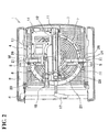
Fig.2 is a top view of a flip-over saw. -
Fig.3 is a perspective view of a guide fence as viewed from the front. -
Fig.4 is a perspective view of a guide fence as viewed from the rear. -
Fig. 5 is a perspective view of a guide fence as viewed from the front, in which a sub fence is detached. -
Fig.6 is a perspective view of a guide fence as viewed from the rear, in which a sub fence is detached. -
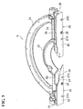
Fig. 7 is an explanatory illustration showing the state of cutting with a sub fence (Here, only the part above a table is illustrated). -
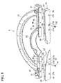
Fig. 8 is an explanatory illustration showing the state of cutting without a sub fence (Here, only the part above a table is illustrated). - An exemplary embodiment of the present invention will be described hereinafter with reference to the accompanying drawings.
- Referring now to
Figs. 1 and2 , a flip-over saw 1 includes abase 2 which is a workbench being rectangular in plan view, a table 3 placed above thebase 2, and a saw-blade unit 4 placed on the table 3. The table 3 is supported by rotatingshafts 5 extending in the right and left direction (right side inFigs. 1 and2 is supposed to be the front.) in such a manner that the table 3 can be flipped over 180°on theshafts 5 and made to be horizontally fixable with either of both sides up by alock lever 6 disposed on thebase 2. Further, around turntable 7 is disposed on the table 3 in such a manner that theturntable 7 can be rotated horizontally. At the same time, aguide fence 8 is mounted in the right and left direction across over theturntable 7. - The saw-blade unit 4 has a holding arm 9 erected at the rear of the
turntable 7 and amain body 11 supported by apivot 10 at the top end of the holding arm 9 in such a manner that it can move vertically. Amotor 13 and ahandle 14 are provided in the right side of ablade cover 12 which is a housing for themain body 11, and a disk-like saw blade 15 rotatably driven by themotor 13 is disposed in theblade cover 12. Themain body 11 is biased toward the top-dead center inFig.1 by a torsion spring (not shown) provided on thepivot 10. When themain body 11 is lowered by pushing of thehandle 14 downward so that thesaw blade 15 penetrates aslit 7a on the center of theturntable 7 down to the bottom-dead center, a workpiece can be cut on theturntable 7 by the rotation of thesaw blade 15. In other words, the saw 1 can be used as a miter saw. Denoted byreference numeral 16 is a safety cover positioned to cover thesaw blade 15 at the top-dead center of themain body 11 and then turned to reveal thesaw blade 15 as themain body 11 is lowered. - The holding arm 9 is tiltable toward the left on the
turntable 7 together with themain body 11, thereby giving thesaw blade 15 an angle with respect to the vertical direction by fixing the arm 9 with alever 17 at any tilting position. With this tilting operation of themain body 11, a bevel cut can be performed on a workpiece on theturntable 7. Theturntable 7, in addition, can be turned horizontally together with themain body 11 by swiveling operation of thehandle 14. By choosing any horizontal rotation angle of theturntable 7, a right-angle cut in which thesaw blade 15 is orthogonal to theguide fence 8, or a miter cut in which thesaw blade 15 is tilted sideways can be performed. - On the other hand, the
main body 11 can be fixed at the bottom-dead center by afixing mechanism 18. In the fixed state, when the table 3 is flipped over, the saw 1 can be used as a table saw where cutting operation is performed by sliding a workpiece on the table 3 against thesaw blade 15 which protrudes over the table 3. - As is illustrated in
Figs. 3 and4 , theguide fence 8 has a pair of right and leftguide sections 20 extending in the right and left direction, and large and small coupling frames 21 and 22 of arcuate shape for coupling theguide sections 20 at the rear. While therotating shafts 5 are respectively held at outer ends of theguide sections 20, theouter coupling frame 21 is fixed on the table 3 by means of screws, and thus the table 3 is rotatably held on thebase 2 through theguide fence 8. - The front part of each
guide section 20 is made to be aseparate sub fence 23. Thesub fence 23 has a box-like block section 24 in the shape of a quadrangle with the longer sides as viewed from the front, and afence section 25 lying in front of theblock section 24. Thefence section 25 is higher than theblock section 24, and a front face of thefence section 25 serves as aguide face 26 perpendicular to the top face of theturntable 7. As is illustrated inFigs.5 and6 , threebosses 27A to 27C are provided on thesub fence 23. The bosses have through holes in the longitudinal direction and are arranged side-by-side in the right and left direction. Among the bosses, thebosses - The front face in the rear part of the
guide section 20 has asecond guide face 29 to which thesub fence 23 is to be fitted. Thesecond guide face 29 has a plane in the shape of a quadrangle with the longer sides and rises upright over the top face of the table 3 and theturntable 7. As for the bottom end of thesecond guide face 29, while the portion ofsecond guide face 29 facing the top face of the table 3 is in contact with the top face of the table 3, the portion of thesecond guide face 29 facing the top face of theturntable 7 has slight level difference so that the portion may come near to the top face of theturntable 7. Ascrew hole 30 and a pair of bottomedholes 31 respectively corresponding to theboss 27B in the center of thesub fence 23 and the right and leftpins 28 are provided on thesecond guide face 29. - The
sub fence 23 can be positioned on thesecond guide face 29 by insertion of thepins 28 into the respective bottomedholes 31 of thesecond guide face 29. With this positioning, thesub fence 23 can be fixed to theguide section 20 by screwing of ascrew 32 into thescrew hole 30 on the second guide face 29 from the front of thesub fence 23 through theboss 27B. The opening portion of theboss 27B on theguide face 26 of thesub fence 23 is in a step shape so that the head of thescrew 32 may be embedded in theboss 27B without protruding from theguide face 26. - The
rear face 24a of theblock section 24 is planarized so that theguide face 26 may be in parallel with thesecond guide face 29 when thesub fence 23 is fitted to theguide section 20. Further, in the state that thesub fence 23 is fitted to theguide section 20, theguide face 26 is flush with the vertical plane passing through the rotational center of theturntable 7 and extending in the right and left direction. Thesecond guide face 29 is in the rearward position retreating from theguide face 26. Anescape section 33 sloping down toward the center is provided on afence section 25 of theleft sub fence 23 so as not to interfere with themain body 11 tilted leftward. - With the flip-over saw 1 configured as described above, when the saw 1 is used as a miter saw with the table 3 in the rotational position as illustrated in
Figs 1 and2 , the fittedguide fence 8 is used for positioning a workpiece. When a workpiece to be cut is within an ordinary cuttable range, the saw 1 is used with the right and leftsub fences 23 respectively fitted to theguide sections 20 as is illustrated inFigs.3 and4 . That is, as above, thepins 28 provided in thesub fence 23 are inserted into the bottomed holes 31 on thesecond guide face 29 and then thesub fence 23 is fitted to thesecond guide face 29 by means of thescrew 32. In this state, as is illustrated inFig.7 , when a workpiece W1 is pushed against the guide faces 26 in such a manner that the workpiece W1 straddles the right and left guide faces 26 to be positioned. When themain body 11 is lowered so that thesaw blade 15 is lowered through the space between the right and left guide faces 26, the workpiece W1 can be cut. The same operation can be done in a bevel cut or a miter cut too. - On the other hand, in the case of a thin and wide workpiece being in contact with the guide faces 26, when the
main body 11 is lowered down to the bottom-dead-center, thesaw blade 15 does not reach the front end of the workpiece. In the case of such workpiece, the saw is used with thesub fences 23 detached from theguide sections 20. Thesub fences 23 can be detached from theguide sections 20 by loosening and removing of thescrew 32 and then thesub fence 23 is pulled forward to draw thepin 28 out of the bottomedhole 31. In this detached state, as is illustrated inFig.8 , when the end of a workpiece W2 is brought into contact with thesecond guide face 29 of theguide section 20 in such a manner that the workpiece W2 extends between the second faces 29. Since the workpiece W2 falls within the cuttable range of thesaw blade 15, the workpiece W2 can be cut by lowering of themain body 11. A bevel cut or a miter cut can be performed of course. - An adjusting block for holding a workpiece near the
saw blade 15 is often used with a bevel cut. The adjusting block, which has substantially the same height and depth as thesub fences 23 and has been made of waste, can be screwed onto thesecond guide face 29 by use of thescrew hole 30 with thesub fence 23 detached from theguide section 20. This way, the saw 1 can be used by fitting of the adjusting block to theguide section 20 with ease. - As described above, with the flip-over saw 1 and the
guide fence 8 according to aforementioned embodiment, the front part of theguide section 20 is made into theseparate sub fence 23 provided with theguide face 26. The face of theguide section 20, to which thesub fence 23 is to be fitted, is made into thesecond guide face 29 in parallel with theguide face 26. Thesecond guide face 29 rises over the top face of aturntable 7 in the rear of theguide face 26. Thesub fence 23 is made detachable from thesecond guide face 29. A workpiece whose width is beyond the cuttable range can be cut by removal of thesub fence 23. Further, a workpiece can be surely positioned without damages even when thesub fence 23 has been removed because thesecond guide face 29 has a plane. The adjusting block and the sub fence can be selectively used with ease, thereby assuring ease-of-use. - In this embodiment, in particular, a
screw hole 30 for fitting thesub fence 23 is provided on thesecond guide face 29, and thus the adjusting block can be fixed to thesecond guide face 29 with ease by thescrew hole 30. - In addition, the rear face of the
sub fence 23 is planarized so that the rear face may be in parallel with theguide face 26. This arrangement improves dimensional accuracy of thesub fence 23, thereby obtaining aprecise guide face 26 when thesub fence 23 is fitted to theguide section 20. - It should be noted that the structure of the sub fence is not necessarily limited to the aforementioned embodiment. The sub fence can be formed of a solid material or the number or the position of a screw or a pin can be changed. Further, the screw can be inserted from the rear of the guide section into the sub fence.
- As for the way of fitting the sub fence to the guide section, moreover, other structure not using a screw and a pin can be adopted as far as detachable fitting is assured. For example, an engaging section like a hook can be installed on the top end of the fence section for engaging the fence section with the guide section across over the second guide face with the sub fence fitted to the guide section and combine the engaging section with a pin.
- It should be also noted that the structure of the guide fence itself is not limited to the aforementioned embodiment. Although right and left guide sections are coupled together by means of a pair of inner and outer coupling frames in aforementioned embodiment, the guide sections can be coupled by means of an inner coupling frame alone. Further, there is no need to provide the guide section with the rotating shaft unless the guide fence is for use in the flip-over saw.
- It should be further noted that the structure of a flip-over saw itself is not limited to the aforementioned embodiment. The present invention is applicable even to the structure allowing a main body to tilt toward both the right and the left or the structure having no function of a bevel cut or a miter cut. Needless to say, the present invention is applicable not only to a flip-over saw but also to other cutting machines like bench-circular sawing machines of the type having a main body on a turntable held over a base in such a manner that the turntable can be horizontally rotated, or of the type without a turntable.
- It is explicitly stated that all features disclosed in the description and/or the claims are intended to be disclosed separately and independently from each other for the purpose of original disclosure as well as for the purpose of restricting the claimed invention independent of the composition of the features in the embodiments and/or the claims. It is explicitly stated that all value ranges or indications of groups of entities disclose every possible intermediate value or intermediate entity for the purpose of original disclosure as well as for the purpose of restricting the claimed invention, in particular as limits of value ranges.
Claims (11)
- A guide fence (8) adapted to be mounted on a table (3) of a cutting machine adapted to hold a main body (11) with a rotationally-driven saw blade (15) on the table (3) in such a manner that the main body (11) can move vertically, and having a laterally-extending guide section (20) having a guide face (26) for positioning a workpiece on front of the guide section (20), characterized in that
a front part of the guide section (20) is made into a detachable separate sub fence (23) having the guide face (26), and a face of the guide section (20) to which the sub fence (23) is to be fitted is made into a second guide face (29) being a plane in parallel with and in the rear of the guide face (26) rising from the top face of the table (3) when mounted on the table (3). - The guide fence (8) according to claim 1, wherein a screw hole (30) for fitting the sub fence (23) to the second guide face (29) is formed on the second guide face (29).
- The guide fence (8) according to claim 2, wherein the sub fence (23) is provided with a boss (27B) through which a screw (32) to be screwed into the screw hole (30) penetrates, the opening part of the boss (27B) on the guide face (26) being in a shape of a step so that the head of the screw (32) is embedded in the boss (27B) without protruding from the guide face (26).
- The guide fence (8) according to any one of claims 1 to 3, wherein the rear face of the sub fence (23) is planarized so as to be in parallel with the guide face (26).
- The guide fence (8) according to any one of claims 1 to 4, wherein, while a pin (28) is provided to protrude rearward on the rear face of the sub fence (23), a bottomed hole (31) is provided on the second guide face (29) so that positioning of the sub fence (23) on the second guide face (29) is carried out by insertion of the pin (28) into the bottomed hole (31).
- The guide fence (8) according to any one of claims 1 to 5, wherein an escape section (33) is provided on the sub fence (23) for preventing a main body (11) of the cutting machine from interfering with the sub fence (23) when the main body (11) is tilted.
- The guide fence (8) according to any one of claims 1 to 6, wherein the guide fence (8) has the pair of right and left guide sections (20) and an arcuate coupling frame (21, 22) for coupling the right and left guide sections (20) at rear of the guide section (20).
- The guide fence (8) according to any one of claims 1 to 7, wherein the sub fence (23) includes a box-like block section (24) in a shape of a quadrangle with the longer sides as viewed from the front and with a depth in the longitudinal direction; and a fence section (25) lying in front of the block section (24), being made higher than the block section (24), and whose front face serves as the guide face (26).
- A cutting machine characterized in that the cutting machine includes;
a table (3);
a main body (11) held on the table (3) in such a manner that the body (11) can move vertically and provided with a rotationally-driven saw blade (15); and
a guide fence (8) to be mounted on the table (3) according to any one of claims 1 to 8. - The cutting machine according to claim 9, wherein a turntable (7) for holding the main body (11) is disposed on the table (3) in such a manner that the turntable (7) can be horizontally rotated, and the guide fence (8) is laterally mounted across over the turntable (7).
- The cutting machine according to claim 9 or 10, wherein a holding arm (9) is erected at the rear of the table (3) and the main body (11) is supported by a pivot (10) at the top end of the holding arm (9) in such a manner that the main body (11) can move vertically.
Applications Claiming Priority (1)
| Application Number | Priority Date | Filing Date | Title |
|---|---|---|---|
| JP2010200139A JP2012055994A (en) | 2010-09-07 | 2010-09-07 | Guide fence, and cutting machine having the same |
Publications (1)
| Publication Number | Publication Date |
|---|---|
| EP2425942A1 true EP2425942A1 (en) | 2012-03-07 |
Family
ID=44651226
Family Applications (1)
| Application Number | Title | Priority Date | Filing Date |
|---|---|---|---|
| EP20110179930 Withdrawn EP2425942A1 (en) | 2010-09-07 | 2011-09-02 | Guide fence and cutting machine having the same |
Country Status (4)
| Country | Link |
|---|---|
| US (1) | US20120055308A1 (en) |
| EP (1) | EP2425942A1 (en) |
| JP (1) | JP2012055994A (en) |
| CN (1) | CN202185640U (en) |
Families Citing this family (7)
| Publication number | Priority date | Publication date | Assignee | Title |
|---|---|---|---|---|
| JP5814137B2 (en) * | 2012-01-19 | 2015-11-17 | 株式会社マキタ | Cutting machine |
| DE102012208310A1 (en) * | 2012-05-18 | 2013-11-21 | Robert Bosch Gmbh | Device for fixing a workpiece to be machined by means of a processing machine |
| JP6100004B2 (en) | 2013-02-01 | 2017-03-22 | 株式会社マキタ | Tabletop cutting machine |
| US9908257B2 (en) * | 2014-09-11 | 2018-03-06 | Robert Bosch Tool Corporation | Adjustable fence assembly for a miter saw |
| JP6450186B2 (en) * | 2014-12-25 | 2019-01-09 | 株式会社ピカコーポレイション | Work cutting device |
| WO2018195868A2 (en) * | 2017-04-27 | 2018-11-01 | 永康市丛臻工具有限公司 | Dust-free multifunctional cutting machine |
| US11095153B2 (en) | 2019-03-15 | 2021-08-17 | Ossia Inc. | Wireless power system technology implemented in lighting infrastructure |
Citations (4)
| Publication number | Priority date | Publication date | Assignee | Title |
|---|---|---|---|---|
| US20040099115A1 (en) * | 2002-11-21 | 2004-05-27 | Salazar Mario A. | Angle gauge |
| JP2006044068A (en) | 2004-08-04 | 2006-02-16 | Makita Corp | Guide fence and cutter |
| US20060266186A1 (en) * | 2005-05-27 | 2006-11-30 | Hiromi Ozawa | Miter saw having compact gear case at cutting portion |
| US20060266182A1 (en) * | 2005-05-12 | 2006-11-30 | Shiraz Balolia | Fence extension for power saws |
Family Cites Families (3)
| Publication number | Priority date | Publication date | Assignee | Title |
|---|---|---|---|---|
| US5816129A (en) * | 1995-12-19 | 1998-10-06 | Singer; David K. | Miter fence for radial arm saw |
| US6128993A (en) * | 1996-10-17 | 2000-10-10 | Zach; Mark | Jig for cutting hardwood flooring to exact lengths |
| US5855366A (en) * | 1997-10-29 | 1999-01-05 | P & F Brother Industrial Corporation | Work supporting device mountable on a worktable of a circular sawing apparatus |
-
2010
- 2010-09-07 JP JP2010200139A patent/JP2012055994A/en active Pending
-
2011
- 2011-07-21 CN CN2011202600632U patent/CN202185640U/en not_active Expired - Fee Related
- 2011-08-31 US US13/222,670 patent/US20120055308A1/en not_active Abandoned
- 2011-09-02 EP EP20110179930 patent/EP2425942A1/en not_active Withdrawn
Patent Citations (4)
| Publication number | Priority date | Publication date | Assignee | Title |
|---|---|---|---|---|
| US20040099115A1 (en) * | 2002-11-21 | 2004-05-27 | Salazar Mario A. | Angle gauge |
| JP2006044068A (en) | 2004-08-04 | 2006-02-16 | Makita Corp | Guide fence and cutter |
| US20060266182A1 (en) * | 2005-05-12 | 2006-11-30 | Shiraz Balolia | Fence extension for power saws |
| US20060266186A1 (en) * | 2005-05-27 | 2006-11-30 | Hiromi Ozawa | Miter saw having compact gear case at cutting portion |
Also Published As
| Publication number | Publication date |
|---|---|
| CN202185640U (en) | 2012-04-11 |
| JP2012055994A (en) | 2012-03-22 |
| US20120055308A1 (en) | 2012-03-08 |
Similar Documents
| Publication | Publication Date | Title |
|---|---|---|
| EP2425942A1 (en) | Guide fence and cutting machine having the same | |
| US10661467B2 (en) | Miter saw with adjustable fence | |
| US8418590B2 (en) | Miter saws having locking assemblies for optimal positioning of cutting blades | |
| EP1842613A1 (en) | A Flip Over Saw | |
| EP1245357B1 (en) | Circular saw with improved corner cutting | |
| EP2580034B1 (en) | A locking construction for a miter saw having a hinged linear guide mechanism | |
| JP2002011702A (en) | Tabletop circular saw vise device | |
| US8413562B2 (en) | Slide circular saw | |
| US7516551B2 (en) | Portable cutting tool | |
| EP1837142A1 (en) | Miter Saw | |
| US7174641B2 (en) | Cutting tool | |
| GB2496406A (en) | Guard mounted on inclining structure of mitre saw | |
| EP1716987B1 (en) | Fence arrangement for a miter saw | |
| KR102151865B1 (en) | Circular sawing machine of electric driving for cutting plate | |
| US20070234865A1 (en) | Table Fence For A Miter Saw With Top Table | |
| EP0949048B1 (en) | Mitre saw with angularly adjustable fence | |
| JP4847098B2 (en) | Cutting machine | |
| EP1623801B9 (en) | Flip over saw | |
| EP1623802A1 (en) | Flip over saw | |
| JP2013078864A (en) | Portable cutting machine | |
| JP2006044068A (en) | Guide fence and cutter | |
| JP2024158145A (en) | Portable cut-off stand and stationary cut-off machine | |
| US20140174272A1 (en) | Power Saw with Blade Guard Retraction Device | |
| KR101839972B1 (en) | Cutting apparatus for excavator | |
| JP4300584B2 (en) | Cutting machine |
Legal Events
| Date | Code | Title | Description |
|---|---|---|---|
| AK | Designated contracting states |
Kind code of ref document: A1 Designated state(s): AL AT BE BG CH CY CZ DE DK EE ES FI FR GB GR HR HU IE IS IT LI LT LU LV MC MK MT NL NO PL PT RO RS SE SI SK SM TR |
|
| AX | Request for extension of the european patent |
Extension state: BA ME |
|
| PUAI | Public reference made under article 153(3) epc to a published international application that has entered the european phase |
Free format text: ORIGINAL CODE: 0009012 |
|
| STAA | Information on the status of an ep patent application or granted ep patent |
Free format text: STATUS: THE APPLICATION IS DEEMED TO BE WITHDRAWN |
|
| 18D | Application deemed to be withdrawn |
Effective date: 20120908 |