EP2425796B1 - Implantation help assembly - Google Patents
Implantation help assembly Download PDFInfo
- Publication number
- EP2425796B1 EP2425796B1 EP10175139.4A EP10175139A EP2425796B1 EP 2425796 B1 EP2425796 B1 EP 2425796B1 EP 10175139 A EP10175139 A EP 10175139A EP 2425796 B1 EP2425796 B1 EP 2425796B1
- Authority
- EP
- European Patent Office
- Prior art keywords
- jaw
- adapter
- patient
- coupling
- plate
- Prior art date
- Legal status (The legal status is an assumption and is not a legal conclusion. Google has not performed a legal analysis and makes no representation as to the accuracy of the status listed.)
- Active
Links
- 238000002513 implantation Methods 0.000 title claims description 20
- 238000010168 coupling process Methods 0.000 claims description 54
- 238000005859 coupling reaction Methods 0.000 claims description 54
- 230000008878 coupling Effects 0.000 claims description 53
- 238000005553 drilling Methods 0.000 claims description 49
- 239000007943 implant Substances 0.000 claims description 35
- 239000003550 marker Substances 0.000 claims description 32
- 238000000034 method Methods 0.000 claims description 8
- 238000003384 imaging method Methods 0.000 claims description 2
- 238000000465 moulding Methods 0.000 claims description 2
- 238000001514 detection method Methods 0.000 description 3
- 238000004519 manufacturing process Methods 0.000 description 3
- 238000010276 construction Methods 0.000 description 2
- 230000013011 mating Effects 0.000 description 2
- 239000002184 metal Substances 0.000 description 2
- 235000008331 Pinus X rigitaeda Nutrition 0.000 description 1
- 235000011613 Pinus brutia Nutrition 0.000 description 1
- 241000018646 Pinus brutia Species 0.000 description 1
- 230000000295 complement effect Effects 0.000 description 1
- 230000003287 optical effect Effects 0.000 description 1
Images


Classifications
-
- A—HUMAN NECESSITIES
- A61—MEDICAL OR VETERINARY SCIENCE; HYGIENE
- A61C—DENTISTRY; APPARATUS OR METHODS FOR ORAL OR DENTAL HYGIENE
- A61C1/00—Dental machines for boring or cutting ; General features of dental machines or apparatus, e.g. hand-piece design
- A61C1/08—Machine parts specially adapted for dentistry
- A61C1/082—Positioning or guiding, e.g. of drills
- A61C1/084—Positioning or guiding, e.g. of drills of implanting tools
Definitions
- the invention relates to an implant aid assembly for implanting a jaw implant in a patient's jaw, wherein the implanted jaw implant is for securing a dental prosthesis to the patient's jaw.
- templates are used which can be placed on the patient's jaw and have a guide bore for drilling the implant bore into the patient's jaw.
- Known implantation auxiliary arrangements and methods for producing a template for drilling an implant bore into the patient's trainee are relatively complicated, inaccurate, error-prone and cumbersome to handle.
- An implantation auxiliary arrangement which has a radio-opaque jaw adapter with coupling parts for attaching a drilling template.
- the jaw adapter For spatial orientation in a radiological three-dimensional image, the jaw adapter has corresponding holes.
- an implant assist device in which the jaw adapter consists of a non-radio-opaque body having integrated radio-opaque reference markers.
- the object of the invention is in contrast to provide an easy-to-use Implant istsangesan extract and an easy-to-use method for producing a template for drilling the implant bore in the patient's jaw.
- the implantation auxiliary arrangement consists of at least three parts, namely a jaw adapter, a separate drilling template and a separate marker plate.
- the jaw adapter has a radiologically non-visible individual molded part, which is adaptable or adapted to the patient's jaw.
- the individual molded part placed on the patient's jaw produces a positive fit with the relevant section of the patient's jaw so that the jaw adapter reproducible and always in the same position and orientation on the patient's jaw rests.
- the jaw adapter provides a spatially unambiguous reference to the patient's jaw.
- the jaw adapter has a radiologically invisible coupling plug, which also allows a spatially reproducible positive coupling with the coupling socket of the drilling template or the marker plate.
- a coupling socket is to be understood as meaning all components which enable a spatially reproducible coupling of the drilling template to the jaw adapter or the marker plate to the jaw adapter.
- the coupling plug or the complementary coupling socket can each be a single complex component, which fulfills this task, but can also each be a plurality of components, which together fulfill this function.
- the marker plate has a radiologically visible three-dimensional 3-D marker, which allows a three-dimensional radiological detection of a spatially unique position and orientation determination of the 3-D marker and its rigidly and uniquely connected parts.
- the 3-D marker can be a single complex component that allows a spatially unambiguous position and orientation determination.
- a prosthesis plate which has at least one radiologically visible denture tooth and a coupling socket, which is clearly coupled together oriented with the coupling plug of the jaw adapter.
- the prosthetic tooth is radiologically visible and represents a planning aid in the virtual planning and construction of the dental prosthesis.
- the prosthesis plate may be formed integrally with the marker plate, so that the prosthesis plate and the marker plate is one and the same component.
- the prosthesis plate is preferably designed as a separate component.
- the jaw adapter has a recess in the region of the patient's jaw in which the dental prosthesis is planned or in which the prosthetic tooth of the prosthesis plate is arranged.
- This recess area coincides with the area of the drill guide bore which in this embodiment directly forms the template for drilling the implant bore into the patient's jaw.
- the jaw adapter therefore preferably has no prosthetic tooth.
- the drilling template directly as Implantbohrung- Schalone.
- the drilling template protrudes into the recess of the prosthesis plate, in particular with its region having the guide bore, so that the overall height of the implant bore template produced in this way is extremely small.
- the jaw adapter has at least one prosthetic tooth which is radiographically visible and represents a planning aid in the virtual computer-aided design and construction of the dental prosthesis.
- the jaw adapter may preferably have a standardized coupling plate with the coupling plug, wherein the coupling plate is fastened on the individual molded part.
- the drilling template is also a standardized template plate that has the coupling socket.
- the property "standardized" in this context means that the coupling plate and the Bohrschablonenplatte are fauxkuppelbar only in a single and known position and orientation to each other. Since their spatial relation to each other is defined and known, the individual molded part, the coupling plate and the Bohrschablonenplatte may be formed radiologically invisible.
- the jaw adapter individual molded part is first molded from the patient's jaw or a real patient's jaw model, for example with the aid of a fast-curing plastic. Subsequently, the coupling plug is attached to the individual molded part, for example, by a standardized coupling plate including the coupling plug connected to the individual molded part, for example glued, is. The individual molded part with the coupling plug or with the coupling plate forms the jaw adapter.
- the marker plate is mounted on the jaw adapter by mating the marker plate-coupling socket with the jaw adapter Kuppfungsstecker, and provided with the marker plate jaw adapter placed on the patient's jaw.
- This situation then becomes radiologically three-dimensional in the form of a corresponding digital three-dimensional jaw image three-dimensional detected, wherein in the jaw image substantially the patient's jaw, and this essentially the jaw bone, and the 3-D markers and optionally the prosthetic tooth are visible.
- the quality, accuracy and resolution of the jaw image can be further improved by further optical recordings and procedures.
- the jaw implant and the requisite Impfantatbohrung in the form of Implantbhrungs position information is planned and set on a computer.
- the guide bore in the surgical template is drilled using the implant bore position information.
- the drilling template already represents an auxiliary drilling template for drilling a guide bore in the jaw adapter or, placed on the jaw adapter, already directly the implant bore template.
- the drilling template is mounted on the jaw adapter by mating the surgical template coupling socket with the jaw adapter coupling plug.
- the placement of a prosthesis plate on the patient's jaw, wherein the prosthesis plate has a radiologically visible prosthetic tooth, and the radiologically three-dimensional detection of an additional jaw image of this situation can be provided.
- the prosthetic tooth visible in the jaw image is a planning aid, in particular when planning the dental prosthesis.
- FIG. 1 a first embodiment of an implantation auxiliary arrangement 10 is shown, which is essentially formed by a jaw adapter 22, a separate drilling template 34 and a separate marker plate 32. Furthermore, in the FIG. 1 a patient's jaw 12 shown having a jaw bone 18, gum 20 and not to be exchanged, so "healthy" teeth 14,15,16.
- the jaw adapter 22 consists of a radiologically non-visible individual molded part 24, a hereby connected, for example glued, standardized and radiologically non-visible coupling plate 26 with a plurality of coupling plugs 28 and optionally one or more radiologically visible prosthetic teeth 61,62,63.
- the jaw adapter 22 is produced by first molding the individual shaped part 24 from the patient's jaw 12 or a real model of the patient's jaw 12 with the aid of a rapidly curing plastic. After curing of the plastic, the individual molded part 24 can be removed from the patient's jaw 12, and the standardized coupling plate 26 is glued to the individual molded part 24.
- prosthetic teeth 61, 62, 63 can be fixed to the individual shaped part to facilitate the subsequent planning of the jaw implants. However, the prosthetic teeth alone are placeholders and facilitate denture and jaw implant planning through their radiological visibility.
- the marker plate 32 is placed by coupling the coupling plugs 28 to the marker plate cupping jacks 30. Subsequently, this arrangement is placed on the patient's jaw 12, and the patient's jaw including the jaw adapter 22 and the marker plate 32 is detected radiologically three-dimensionally using a DVT device. Optionally, additional imaging techniques may be used to be able to create the resulting pine picture more accurately. Subsequently, the marker plate 32 is removed again from the jaw adapter 22.
- the marker plate 32 has a plurality of 3-D markers 36 in the form of radiologically visible metal spheres, which are cast into the plastic marker plate body 33 and have a diameter of about 1.0 mm.
- the dental prostheses and the associated jaw implants are virtually planned on a computer.
- the position and orientation of the jaw implants are determined with respect to the patient's jaw 12.
- the position information of the associated implant bores 71, 72, 73 in the patient's jaw 12 or in the jawbone 18 is determined or determined.
- the implant bore location information is then communicated to the location where corresponding pilot holes 41, 42, 43 are drilled in the surgical template 34 by a digitally controlled drill using the implant bore location information.
- the drilling template 34 is essentially formed by a plastic body 35 having coupling bushes 30 on one side, by means of which a form-locking coupling with the coupling plugs 28 of the jaw adapter 42 can be produced.
- the guide bores 41, 42, 43 are drilled in the drilling template 34 in such a way that they would be aligned with the planned implant bores 71, 42, 73 when the drilling template 34 was mounted on the jaw adapter 22 and the jaw adapter was placed on the patient jaw 12, which is the case However, because of the limited space in the patient's mouth is not possible.
- the surgical template 34 is first extraorally coupled to the jaw adapter 22, and boring pilot bores 51, 52, 53 in the jaw adapter 22 in alignment with the drill tunnel guide bores 41, 42, 43 with a drill.
- the drilling shaft of the drill is guided through the drilling template guide holes 41,42,43.
- the drilling template 34 is removed from the jaw adapter 22.
- metal guide sleeves can be inserted into the jaw adapter guide bores 51, 52, 53.
- the jaw adapter 22 processed in this way is now a template for drilling the implant bores 71, 72, 73.
- the jaw adapter 22 is again placed on the patient's jaw 12.
- the implant bores 71, 72, 73 are bored in alignment with the jaw adapter guide bores 51, 52, 53 into the patient's jaw 12 with a drill, and the jaw adapter 22 is finally removed from the patient's jaw 12.
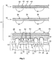
- FIG. 2 and 3 A second embodiment of an implantation aid arrangement 10 'is shown, which is essentially formed by a jaw adapter 90, a separate marker plate 32, a prosthesis plate 80 and a drilling template 88.
- the jaw adapter 90 is provided with a recess 94 in the area in which the dental prostheses and therefore also the implant bores 71 ', 72', 73 'are provided in the patient jaw 12, see FIG. 3 ,
- the drilling template 88 with the guide holes 41 ', 42', 43 'in the Bohrschabionen body 89 finally placed on the jaw adapter 90, and in this combination already directly as a template for drilling the implant bore in 71', 72 ' , 73 'serve.
- the jaw adapter 90 of the Figures 2 and 3 is presently shown as a one-piece body 91, but may also be composed of an individual molded part and a standardized coupling plate.
- an intermediate step may be provided, namely the use of the prosthesis plate 80, which has on the prosthesis plate body 81 a plurality of prosthetic teeth 61 ', 62', 63 'as a planning aid, which are radiologically visible.
- the prosthesis plate 80 is placed on the jaw adapter 90, and the combination of prosthesis plate 80 and jaw adapter 90 is then placed on the patient's jaw 12. This arrangement is radiologically detected three-dimensionally, and superimposed on the thus obtained additional jaw image with the jaw image, which is made by the patient's jaw, on which the jaw adapter 90 sits with the marker plate 32.
- the use of the prosthesis plate 80 can be dispensed with, for example and in particular if the original teeth to be replaced by the dental prosthesis still sit in the patient's jaw 12 during the radiological detection of the jaw image.
- the prosthesis mat 80 can also be dispensed with if the dental prostheses are planned exclusively with the help of the jaw image on the computer, and the dental prostheses are obtained, for example, from a virtual library.
- the 3-D markers 36 in this embodiment can also be cast into the jaw adapter 90 and / or in the prosthesis plate 80, so that a separate marker plate 32 would then be omitted.
- the drilling template 88 can protrude into the recess 94 of the jaw adapter 90 in the direction of the patient's jaw 12, in particular with its region having the guide bores 41 ', 42', 43 ' that the coupled combination of the jaw adapter 90 and the drilling template 88 is very compact.
Description
Die Erfindung bezieht sich auf eine Implantierungshilfsanordnung für das Implantieren eines Kieferimplantats in einem Patientenkiefer, wobei das implantierte Kieferimplantat zur Befestigung einer Zahnprothese an den Patientenkiefer dient.The invention relates to an implant aid assembly for implanting a jaw implant in a patient's jaw, wherein the implanted jaw implant is for securing a dental prosthesis to the patient's jaw.
Bei dem gesamten Prozess, der dem eigentlichen Implantieren des Kieferimplantats vorausgeht, ist insbesondere die räumlich exakte Bohrung der Implantatbohrung in dem Patientenkiefer von großer Bedeutung. Zum Bohren der Implantatbohrung werden daher Schablonen verwendet, die auf den Patientenkiefer aufsetzbar sind und eine Führungsbohrung zum Bohren der Implantatbohrung in den Patientenkiefer aufweisen. Bekannte Implantierungshilfsanordnungen und Verfahren zur Herstellung einer Schablone zum Bohren einer Implantatbohrung in den Patientenklefer sind relativ aufwändig, ungenau, fehlerträchtig und umständlich in der Handhabung.In the entire process, which precedes the actual implantation of the jaw implant, particularly the spatially exact drilling of the implant bore in the patient's jaw is of great importance. For drilling the implant bore, therefore, templates are used which can be placed on the patient's jaw and have a guide bore for drilling the implant bore into the patient's jaw. Known implantation auxiliary arrangements and methods for producing a template for drilling an implant bore into the patient's trainee are relatively complicated, inaccurate, error-prone and cumbersome to handle.
Aus
Aus der nachveröffentlichten
Aufgabe der Erfindung ist es demgegenüber, eine einfach anzuwendende Implantierungshilfsanordnung und ein einfach anzuwendendes Verfahren zur Herstellung einer Schablone zum Bohren der Implantatbohrung in den Patientenkiefer zu schaffen.The object of the invention is in contrast to provide an easy-to-use Implantierungshilfsanordnung and an easy-to-use method for producing a template for drilling the implant bore in the patient's jaw.
Diese Aufgabe wird erfindungsgemäß gelöst durch eine Implantierungshilfsanordnung gemäß Anspruch 1 beziehungsweise durch ein Verfahren zur Herstellung einer Implantierungshilfsanordnung gemäß Anspruch 7.This object is achieved by a Implantierungshilfsanordnung according to
Die erfindungsgemäße Implantierungshilfsanordnung besteht mindestens aus drei Teilen, nämlich einem Kieferadapter, einer separaten Bohrschablone und einer separaten Markerplatte.The implantation auxiliary arrangement according to the invention consists of at least three parts, namely a jaw adapter, a separate drilling template and a separate marker plate.
Der Kieferadapter weist ein radiologisch nicht-sichtbares Individualformteil auf, das an den Patientenkiefer anpassbar beziehungsweise angepasst ist. Das auf den Patientenkiefer aufgesetzte Individualformteil stellt mit dem betreffenden Abschnitt des Patientenkiefers einen Formschluss her, so dass der Kieferadapter reproduzierbar und stets in der gleichen Position und Orientierung auf dem Patientenkiefer aufliegt. Der Kieferadapter stellt eine räumlich eindeutige Referenz zu dem Patientenkiefer her.The jaw adapter has a radiologically non-visible individual molded part, which is adaptable or adapted to the patient's jaw. The individual molded part placed on the patient's jaw produces a positive fit with the relevant section of the patient's jaw so that the jaw adapter reproducible and always in the same position and orientation on the patient's jaw rests. The jaw adapter provides a spatially unambiguous reference to the patient's jaw.
Der Kieferadapter weist einen radiologisch nicht sichtbaren Kupplungsstecker auf, der mit der Kupplungsbuchse der Bohrschablone beziehungsweise der Markerplatte ebenfalls eine räumlich reproduzierbare formschlüssig Kupplung ermöglicht. Unter einer Kupplungsbuchse sind alle Bauelemente zu verstehen, die eine räumlich reproduzierbare Kupplung der Bohrschablone an den Kieferadapter beziehungsweise der Markerplatte an den Kieferadapters ermöglichen. Der Kupplungsstecker beziehungsweise die komplementäre Kupplungsbuchse können jeweils ein einziges komplexes Bauteil sein, das diese Aufgabe erfüllt, können jedoch auch jeweils mehrerer Bauteile sein, die zusammen diese Funktion erfüllen.The jaw adapter has a radiologically invisible coupling plug, which also allows a spatially reproducible positive coupling with the coupling socket of the drilling template or the marker plate. A coupling socket is to be understood as meaning all components which enable a spatially reproducible coupling of the drilling template to the jaw adapter or the marker plate to the jaw adapter. The coupling plug or the complementary coupling socket can each be a single complex component, which fulfills this task, but can also each be a plurality of components, which together fulfill this function.
Die Markerplatte weist einen radiologisch sichtbaren dreidimensionalen 3-D-Marker auf, der bei seiner dreidimensionalen radiologischen Erfassung eine räumlich eindeutige Lage- und Orientierungs-Bestimmung des 3-D-Markers und der mit ihm starr und eindeutig verbundenen Teile erlaubt. Der 3-D-Marker kann ein einziges komplexes Bauteil sein, das eine räumlich eindeutige Lage- und Orientierung-Bestimmung erlaubt. Es können jedoch auch mehrere einzelne 3-D-Marker vorgesehen sein, die beispielsweise als radiologisch sichtbare kleine Kugeln mit jeweils einem Durchmesser von 0,5 bis circa 3 mm ausgebildet sind. Wenn die Markerplatte an den Kieferadapter angekuppelt und der Kieferadapter auf dem Patientenkiefer aufgesetzt ist, wird auf diese Weise eine eindeutige räumliche Beziehung zwischen dem Patientenkiefer und dem Kieferadapter hergestellt beziehungsweise radiologisch sichtbar gemacht. Auch die Markerplatte weist eine bevorzugt radiologisch nicht-sichtbare Kupplungsbuchse auf, die mit dem Kupplungsstecker des Kieferadapters räumliche eindeutig zusammenkuppelbar ist.The marker plate has a radiologically visible three-dimensional 3-D marker, which allows a three-dimensional radiological detection of a spatially unique position and orientation determination of the 3-D marker and its rigidly and uniquely connected parts. The 3-D marker can be a single complex component that allows a spatially unambiguous position and orientation determination. However, it is also possible to provide a plurality of individual 3-D markers, which are designed, for example, as radiologically visible small spheres, each having a diameter of 0.5 to approximately 3 mm. When the marker plate is coupled to the jaw adapter and the jaw adapter is placed on the patient's jaw, a clear spatial relationship between the patient's jaw and the jaw adapter is produced or made radiologically visible in this way. Also, the marker plate has a preferably non-radiologically radiatable coupling socket, which is clearly zusammenkuppelbar with the coupling plug of the jaw adapter spatial.
Gemäß einer ersten bevorzugten Ausführungsform der Impfantierungshiffsanordnung ist eine Prothesenplatte vorgesehen, die mindestens einen radiologisch sichtbaren Prothesenzahn und eine Kupplungsbuchse aufweist, die mit dem Kupplungsstecker des Kieferadapters eindeutig orientiert zusammenkuppelbar ist. Der Prothesenzahn ist radiologisch sichtbar und stellt eine Planungshilfe bei der virtuellen Planung und Konstruktion der Zahnprothese dar.According to a first preferred embodiment of the Impfantierungshiffsanordnung a prosthesis plate is provided which has at least one radiologically visible denture tooth and a coupling socket, which is clearly coupled together oriented with the coupling plug of the jaw adapter. The prosthetic tooth is radiologically visible and represents a planning aid in the virtual planning and construction of the dental prosthesis.
Die Prothesenplatte kann mit der Markerplatte einstückig ausgebildet sein, so dass die Prothesen platte und die Markerplatte ein und dasselbe Bauteil ist. Bevorzugt ist die Prothesenplatte jedoch als ein separates Bauteil ausgebildet.The prosthesis plate may be formed integrally with the marker plate, so that the prosthesis plate and the marker plate is one and the same component. However, the prosthesis plate is preferably designed as a separate component.
Besonders bevorzugt weist der Kieferadapter in dem Bereich des Patientenkiefers, in dem die Zahnprothese geplant ist beziehungsweise in dem der Prothesenzahn der Prothesenplatte angeordnet ist, eine Ausnehmung auf. Dieser Ausnehmungs-Bereich deckt sich mit dem Bereich der Bohrschabionen-Führungsbohrung, die bei dieser Ausführungsform unmittelbar die Schablone zum Bohren der Implantatbohrung in den Patientenkiefer bildet. Der Kieferadapter weist daher bevorzugt keinen Prothesenzahn auf. Durch die Kieferadapter-Ausnehmung ist es möglich, die Bohrschablone direkt als Implantatbohrungs-Schalone zu verwenden. Besonders bevorzugt ragt die Bohrschablone insbesondere mit ihrem die Führungsbohrung aufweisenden Bereich in die Ausnehmung der Prothesenplatte hinein, so dass die Bauhöhe der auf diese Weise hergestellten Implantatbohrungs-Schablone extrem gering ist.Particularly preferably, the jaw adapter has a recess in the region of the patient's jaw in which the dental prosthesis is planned or in which the prosthetic tooth of the prosthesis plate is arranged. This recess area coincides with the area of the drill guide bore which in this embodiment directly forms the template for drilling the implant bore into the patient's jaw. The jaw adapter therefore preferably has no prosthetic tooth. Through the jaw adapter recess, it is possible to use the drilling template directly as Implantbohrung- Schalone. Particularly preferably, the drilling template protrudes into the recess of the prosthesis plate, in particular with its region having the guide bore, so that the overall height of the implant bore template produced in this way is extremely small.
Gemäß einer zweiten Ausführungsform, die eine Alternative zur ersten Ausführungsform darstellt, weist der Kieferadapter mindestens einen Prothesenzahn auf, der radiologisch sichtbar ist, und eine Pianungshilfe bei der virtuellen computergestützten Planung und Konstruktion der Zahnprothese darstellt.In accordance with a second embodiment, which is an alternative to the first embodiment, the jaw adapter has at least one prosthetic tooth which is radiographically visible and represents a planning aid in the virtual computer-aided design and construction of the dental prosthesis.
Vorzugsweise kann der Kieferadapter bei beiden Ausführungsformen eine standardisierte Kupplungsplatte mit dem Kupplungsstecker aufweisen, wobei die Kupplungsplatte auf dem Individualformteil befestigt ist. Auch die Bohrschablone ist eine standardisierte Bohrschablonenplatte, die die Kupplungsbuchse aufweist. Die Eigenschaft "standardisiert" bedeutet in diesem Zusammenhang, dass die Kupplungsplatte und die Bohrschablonenplatte nur in einer einzigen und bekannten Lage und Orientierung zueinander zusammenkuppelbar sind. Da ihr räumlicher Bezug zueinander festgelegt und bekannt ist, können das Individualformteil, die Kupplungsplatte und die Bohrschablonenplatte radiologisch nicht-sichtbar ausgebildet sein. Ferner ist es hierdurch möglich, die Führungsbohrung mit Hilfe von bei der virtuellen Zahnprothesen-Planung generierten Implantatbohrungs-Lageinformationen die Führungsbohrung durch eine Werkzeugmaschine an einem von dem Patientenkiefer und dem Kieferadapter entfernten Ort herzustellen, und erst nach der Herstellung an den Behandlungsort zu übersenden.In both embodiments, the jaw adapter may preferably have a standardized coupling plate with the coupling plug, wherein the coupling plate is fastened on the individual molded part. The drilling template is also a standardized template plate that has the coupling socket. The property "standardized" in this context means that the coupling plate and the Bohrschablonenplatte are zusammenkuppelbar only in a single and known position and orientation to each other. Since their spatial relation to each other is defined and known, the individual molded part, the coupling plate and the Bohrschablonenplatte may be formed radiologically invisible. Furthermore, it is thereby possible to produce the guide bore with the aid of implant implant position information generated in the virtual dental prosthesis planning, the guide bore by a machine tool at a location remote from the patient's jaw and the jaw adapter, and to transmit it to the treatment site only after production.
Gemäß dem Verfahrensanspruch 7 wird zunächst das Kieferadapter-Individualformteil von dem Patientenkiefer oder einem realen Patientenkiefer-Modell abgeformt, beispielsweise mit Hilfe eines schnell aushärtenden Kunststoffes. Anschließend wird der Kupplungsstecker an das Individualformteil angebracht, beispielsweise, indem eine standardisierte Kupplungsplatte einschließlich des Kupplungssteckers mit dem Individualformteil verbunden, beispielsweise verklebt, wird. Das Individualformteil mit dem Kupplungsstecker beziehungsweise mit der Kupplungsplatte bildet den Kieferadapter.According to the method claim 7, the jaw adapter individual molded part is first molded from the patient's jaw or a real patient's jaw model, for example with the aid of a fast-curing plastic. Subsequently, the coupling plug is attached to the individual molded part, for example, by a standardized coupling plate including the coupling plug connected to the individual molded part, for example glued, is. The individual molded part with the coupling plug or with the coupling plate forms the jaw adapter.
Anschließend wird die Markerplatte an dem Kieferadapter durch Zusammenstecken der Markerplatte-Kupplungsbuchse mit dem Kieferadapter-Kuppfungsstecker montiert, und der mit der Markerplatte versehene Kieferadapter auf den Patientenkiefer aufgesetzt. Diese Situation wird dann radiologisch dreidimensional in Form eines entsprechenden digitalen dreidimensionalen Kieferbildes dreidimensional erfasst, wobei in dem Kieferbild im wesentlichen der Patientenkiefer, und hierbei im wesentlichen der Kieferknochen, sowie der 3-D-Marker und gegebenenfalls der Prothesenzahn sichtbar sind. Die Qualität, Genauigkeit und Auflösung des Kieferbildes kann durch weitere optische Aufnahmen und Verfahren noch verbessert werden.Subsequently, the marker plate is mounted on the jaw adapter by mating the marker plate-coupling socket with the jaw adapter Kuppfungsstecker, and provided with the marker plate jaw adapter placed on the patient's jaw. This situation then becomes radiologically three-dimensional in the form of a corresponding digital three-dimensional jaw image three-dimensional detected, wherein in the jaw image substantially the patient's jaw, and this essentially the jaw bone, and the 3-D markers and optionally the prosthetic tooth are visible. The quality, accuracy and resolution of the jaw image can be further improved by further optical recordings and procedures.
Mit Hilfe des auf diese Weise gewonnenen dreidimensionalen Kieferbildes wird an einem Computer das Kieferimplantat sowie die hierfür erforderliche Impfantatbohrung in Form von Implantatbohrungs-Lageinformationen geplant und festgelegt.With the aid of the three-dimensional jaw image obtained in this way, the jaw implant and the requisite Impfantatbohrung in the form of Implantbhrungs position information is planned and set on a computer.
Anschließend wird die Führungsbohrung in der Bohrschablone mit Hilfe der Implantatbohrungs-Lageinformationen gebohrt. Hierbei wird bezüglich der Lage der Führungsbohrung der Bohrschablone berücksichtigt, ob die Bohrschablone entweder eine Hilfs-Bohrschablone zum Bohren einer Führungsbohrung in dem Kieferadapter, oder aber, aufgesetzt auf den Kieferadapter, bereits unmittelbar die Implantatbohrungs-Schablone darstellt.Subsequently, the guide bore in the surgical template is drilled using the implant bore position information. In this case, it is taken into account with regard to the position of the guide bore of the drilling template whether the drilling template already represents an auxiliary drilling template for drilling a guide bore in the jaw adapter or, placed on the jaw adapter, already directly the implant bore template.
Anschließend wird die Bohrschablone an dem Kieferadapter durch Zusammenstecken der Bohrschablonen-Kupplungsbuchse mit dem Kieferadapter-Kupplungsstecker montiert.Subsequently, the drilling template is mounted on the jaw adapter by mating the surgical template coupling socket with the jaw adapter coupling plug.
Als Zwischenschritt vor der Planung der Zahnprothese kann das Aufsetzen einer Prothesenplatte auf den Patientenkiefer, wobei die Prothesenplatte einen radiologisch sichtbaren Prothesenzahn aufweist, und das radiologisch dreidimensionale Erfassen eines zusätzlichen Kieferbildes dieser Situation vorgesehen sein. Der in dem Kieferbild sichtbarer Prothesenzahn ist eine Planungshilfe insbesondere bei der Planung der Zahnprothese. As an intermediate step prior to the planning of the dental prosthesis, the placement of a prosthesis plate on the patient's jaw, wherein the prosthesis plate has a radiologically visible prosthetic tooth, and the radiologically three-dimensional detection of an additional jaw image of this situation can be provided. The prosthetic tooth visible in the jaw image is a planning aid, in particular when planning the dental prosthesis.
Gemäß einer zweiten alternativen Ausführungsform des weiteren Verfahrens, das sich auf die Implantierungshilfsanordnung gemäß Anspruch 3 bezieht, ist nach der Bohrschablonen-Montage vorgesehen, zunächst mit Hilfe der Bohrschablone in den Kieferadapter eine Führungsbohrung in Ausrichtung mit der Bohrschablone-Führungsbohrung zu bohren, Daraufhin wird die Bohrschablone von dem Kieferadapter wieder entfernt und wird alleine der Kieferadapter in den Patientenkiefer eingesetzt.According to a second alternative embodiment of the further method, which relates to the Implantierungshilfsanordnung according to claim 3, is provided after the drilling template assembly, first with the help of the drilling template in the jaw adapter to drill a guide bore in alignment with the drilling template guide bore, then the Drill template removed from the jaw adapter again and alone the jaw adapter is inserted into the patient's jaw.
Im folgenden werden zwei Ausführungsbeispiele der Erfindung anhand der Zeichnungen näher erläutert.In the following two embodiments of the invention will be explained in more detail with reference to the drawings.
Es zeigen:
-
Figur 1 -
Figur 2 ein Sagittalebenen-Schnitt einer zweiten Ausführungsform einer Implantierungshilfsanordnung, die von einem Kieferadapter, einer Bohrschablone, einer Markerplatte und einer Prothesenplatte gebildet wird, und -
Figur 3 eine Draufsicht auf den auf den Patientenkiefer aufgesetzten Kieferadapter der implantierungshilfsanordnung derFigur 2 .
-
FIG. 1 a sagittal plane section of a first embodiment of an implantation auxiliary arrangement, which is formed by a jaw adapter, a surgical template and a marker plate, -
FIG. 2 a sagittal plane section of a second embodiment of an implantation auxiliary arrangement, which is formed by a jaw adapter, a surgical template, a marker plate and a prosthesis plate, and -
FIG. 3 a plan view of the patch on the patient jaw jaw adapter implantierungshilfsanordnung theFIG. 2 ,
In der
Der Kieferadapter 22 besteht aus einem radiologisch nicht-sichtbaren Individualformteil 24, einer hiermit verbundenen, beispielsweise verklebten, standardisierten und radiologisch nicht-sichtbaren Kupplungsplatte 26 mit mehreren Kupplungssteckern 28 sowie gegebenenfalls einem oder mehreren radiologisch sichtbaren Prothesenzähnen 61,62,63. Der Kieferadapter 22 wird hergestellt, indem zunächst das Individualformteil 24 von dem Patientenkiefer 12 oder einem realen Modell des Patientenkiefers 12 mit Hilfe eines schnell aushärtenden Kunststoffs abgeformt wird. Nach dem Aushärten des Kunststoffes kann das Individualformteil 24 von dem Patientenkiefer 12 abgenommen werden, und wird die standardisierte Kupplungsplatte 26 mit dem Individualformteil 24 verklebt. Ferner können an dem Individualformteil zur Erleichterung der spätere Planung der Kieferimplantate Prothesenzähnen 61,62 ,63 fixiert werden. Die Prothesenzähne sind jedoch alleine Platzhalter und erleichtern durch ihre radiologische Sichtbarkeit die Zahnprothesen- und Kieferimplantat-Planung.The
Auf den auf diese Weise hergestellten Kieferadapter 22 wird die Markerplatte 32 durch Verkuppeln der Kupplungsstecker 28 mit den Markerpiatten-Kuppfungsbuchsen 30 aufgesetzt. Anschließend wird diese Anordnung auf den Patientenkiefer 12 aufgesetzt, und wird der Patientenkiefer einschließlich des Kieferadapters 22 und der Markerplatte 32 mit Hilfe eines DVT-Gerätes radiologisch dreidimensional erfasst. Optional können zusätzlich weitere bildgebende Verfahren verwendet werden, um das hieraus resultierende Kieferbild genauer erstellen zu können. Anschließend wird die Markerplatte 32 wieder von dem Kieferadapter 22 abgenommen.On the
Die Markerplatte 32 weist mehrere 3-D-Marker 36 in Form von radiologisch sichtbaren Metall-Kugeln auf, die in den Kunststoff-Markerplatten-Körper 33 eingegossen sind und einen Durchmesser von circa 1,0 mm aufweisen.The
Nach dem Erfassen des dreidimensionalen Kieferbildes werden an einem Computer virtuell die Zahnprothesen und die dazugehörigen Kieferimplantate geplant. Insbesondere werden hierbei jeweils auch die Position und Orientierung der Kieferimplantate in Bezug auf den Patientenkiefer 12 festgelegt, Hierbei werden auch die Lageinformationen der zugeordneten Implantatbohrungen 71,72 ,73 in dem Patientenkiefer 12 beziehungsweise in dem Kieferknochen 18 festgelegt beziehungsweise ermittelt.After acquiring the three-dimensional jaw image, the dental prostheses and the associated jaw implants are virtually planned on a computer. In particular, in this case also the position and orientation of the jaw implants are determined with respect to the patient's
Die Implantatbohrung-Lageinformationen werden anschließend an den Ort übermittelt, an dem mit Hilfe der Implantatbohrung-Lageinformationen Entsprechende Führungsbohrungen 41,42,43 in die Bohrschablone 34 durch eine digital gesteuerte Bohrmaschine gebohrt werden. Die Bohrschablone 34 wird im wesentlichen von einem Kunststoff-Körper 35 gebildet, der an einer Seite Kupplungsbuchsen 30 aufweist, mit deren Hilfe eine formschlüssige Verkopplung mit den Kupplungssteckern 28 des Kieferadapters 42 hergestellt werden kann.The implant bore location information is then communicated to the location where corresponding
Die Führungsbohrungen 41,42 ,43 werden derart in die Bohrschablone 34 gebohrt, dass diese mit den geplanten Implantatbohrungen 71,42 ,73 fluchten würden, wenn die Bohrschablone 34 auf dem Kieferadapter 22 montiert und der Kieferadapter auf dem Patientenkiefer 12 aufgesetzt wäre, was so jedoch wegen der beengten Platzverhältnisse in dem Mund des Patienten nicht möglich ist.The guide bores 41, 42, 43 are drilled in the
Daher wird die Bohrschablone 34 zunächst extraoral an den Kieferadapter 22 angekuppelt, und werden mit einer Bohrmaschine manuell Führungsbohrungen 51,52,53 in dem Kieferadapter 22 in Ausrichtung mit den Bohrschabionen-Führungsbohrungen 41,42,43 gebohrt. Der Bohrschaft der Bohrmaschine wird dabei durch die Bohrschablone-Führungsbohrungen 41,42,43 geführt. Anschließend wird die Bohrschablone 34 von dem Kieferadapter 22 abgenommen. Anschließend können, müssen jedoch nicht, Metall-Führungshülsen in die Kieferadapter-Führungsbohrungen 51,52,53 eingesetzt werden.Therefore, the
Der auf diese Weise bearbeitete Kieferadapter 22 ist nun eine Schablone zum Bohren der Implantatbohrungen 71,72,73. Der Kieferadapter 22 wird hierzu wieder auf den Patientenkiefer 12 aufgesetzt. Dann werden mit einer Bohrmaschine manuell die Implantatbohrungen 71,72,73 in Ausrichtung mit den Kieferadapter-Führungsbohrungen 51,52,53 in den Patientenkiefer 12 gebohrt, und der Kieferadapter 22 schließlich von dem Patientenkiefer 12 abgenommen.The
In den
Im Unterschied zu der Imptantierungshitfsanordnung 10 der
Der Kieferadapter 90 der
Optional kann ein Zwischenschritt vorgesehen werden, nämlich die Verwendung der Prothesenplatte 80, die an dem Prothesenplatten.Körper 81 mehrere Prothesenzähne 61',62',63' als Planungshilfe aufweist, die radiologisch sichtbar sind. Die Prothesenplatte 80 wird auf den Kieferadapter 90 aufgesetzt, und die Kombination aus Prothesenplatte 80 und Kieferadapter 90 wird anschließend auf den Patientenkiefer 12 aufgesetzt. Diese Anordnung wird radiologisch dreidimensional erfasst, und das auf diese Weise gewonnene zusätzliche Kieferbild mit dem Kieferbild überlagert, das von dem Patientenkiefer gemacht wird, auf den der Kieferadapters 90 mit der Markerplatte 32 sitzt.Optionally, an intermediate step may be provided, namely the use of the
Grundsätzlich kann die Verwendung der Prothesenplatte 80 jedoch entfallen, beispielsweise und insbesondere dann, wenn die durch die Zahnprothese zu ersetzenden Original-Zähne bei der radiologischen Erfassung des Kieferbildes noch in dem Patientenkiefer 12 sitzen. Auf die Prothesenptatte 80 kann auch dann verzichtet werden, wenn die Zahnprothesen ausschließlich mit Hilfe des Kieferbildes am Computer geplant werden, und die Zahnprothesen beispielsweise aus einer virtuellen Bibliothek bezogen werden.In principle, however, the use of the
Grundsätzlich können die 3-D-Marker 36 bei dieser Ausführungsform auch in den Kieferadapter 90 und/oder in der Prothesenplatte 80 eingegossen sein, so dass dann eine separate Markerplatte 32 entfallen würde.In principle, the 3-
Die Bohrschablone 88 kann insbesondere mit ihrem die Führungsbohrungen 41',42',43' aufweisenden Bereich in die Ausnehmung 94 des Kieferadapters 90 in Richtung Patientenkiefer 12 hineinragen, so dass die zusammengekoppelte Kombination aus dem Kieferadapter 90 und der Bohrschablone 88 sehr kompakt ist.The
Claims (8)
- Implantation aid assembly (10; 10') for the implantation of a jaw implant into a patient's jaw (12) intended for the support of a dental prosthesis, with:a jaw adapter (22; 90) which comprises
an individualized molded part (24; 91) adaptable to a patient's jaw (12), which is individual and adaptable to a patient's jaw (12) such that the jaw adapter (22; 90) can be set on a patient's jaw (12) in a reproducible and form-fitting manner, and
a coupling pin (28), wherein the individualized molded part (24; 91) and the coupling plug (28) are radiologically invisible,a separate drilling jig (34; 88) comprising
a guide bore (41, 42, 43; 41', 42', 43') for drilling a guide bore (51, 52, 53) into the jaw adapter (22; 90) or an implant bore (71', 72', 73') into a patient's jaw (12), and
a coupling socket (30) adapted to be coupled with the coupling pin (28) in a spatially distinct and defined manner to form a coupling arrangement, anda separate marker plate (32) comprising
a radiologically visible 3D marker (36) which, with the maker plate (32) coupled to the jaw adapter (22; 90) and the jaw adapter (22; 90) set on a patient's jaw (12), defines the spatial relationship between a patient's jaw (12) and the jaw adapter (22; 90), and
a coupling socket (30) adapted to be coupled with the coupling pin (28) in a spatially distinct and defined manner to form a coupling arrangement. - Implantation aid assembly (10') of claim 1, comprising a prosthesis plate (80) having at least one prosthetic tooth (61', 62', 63') that is radiologically visible and a coupling socket (30) adapted to be coupled with the coupling pin (28) in a spatially distinct and defined manner to form a coupling arrangement.
- Implantation aid assembly (10) of claim 1, wherein the jaw adapter (22) has at least one prosthetic tooth (61, 62, 63) that is radiologically visible.
- Implantation aid assembly (10') of claim 1 or 2, wherein the jaw adapter (90) has no prosthetic tooth (61', 62', 63').
- Implantation aid assembly (10') of claim 4, wherein the jaw adapter (90) has a recess (94) in alignment with the drilling jig guide bore (41', 42', 43').
- Implantation aid assembly (10) of one of the preceding claims 1 or 3, wherein the jaw adapter (22) comprises a standardized coupling plate (26) with the coupling pin (28), the plate being fastened on the individualized molded part (24), and wherein the drilling jig (34) is a standardized drilling jig plate (35) with the coupling socket (30), wherein the guide bore (41, 42, 43) has been drilled into the drilling jig plate (35) by means of a machine tool using implant bore position information.
- Method for making an implantation aid assembly (10, 10') of one of the preceding claims, the method comprising the steps of:molding the individualized molded part (24; 91) of the jaw adapter from a patient's jaw (12) or a model of a patient's jaw,attaching the coupling pin (28) to the individualized molded part (24; 91),assembling the marker plate (32) to the jaw adapter (22; 90) by fitting the marker plate coupling socket (30) and the jaw adapter coupling pin (28) together,setting the jaw adapter (22; 90) provided with the marker plate (32) on a patient's jaw (12),three-dimensional radiological imaging of a jaw image of a patient's jaw (12) and the 3D marker (36),virtual construction and determining of the position information of an implant bore for the jaw implant in the three-dimensional jaw image,drilling the guide bore (41, 42, 43; 41', 42', 43') in the drilling jig (34; 88) using the implant bore position information, andassembling the drilling jig (34; 88) to the jaw adapter (22; 90) by fitting the drilling jig coupling socket (30) and the jaw adapter coupling pin (28) together.
- Method for making an implantation aid assembly (10) of claim 7 for making an implantation aid assembly of claim 3, including the following steps subsequent to the assembly of the drilling jig:drilling a guide bore (51, 52, 53) in the jaw adapter (22) in alignment with the drilling jig guide bore (41, 42, 43), andremoving the drilling jig (34) from the jaw adapter (22).
Priority Applications (2)
| Application Number | Priority Date | Filing Date | Title |
|---|---|---|---|
| EP10175139.4A EP2425796B1 (en) | 2010-09-02 | 2010-09-02 | Implantation help assembly |
| EP20100189051 EP2425797B1 (en) | 2010-09-02 | 2010-10-27 | Implant assistance assembly for implanting a jaw implant |
Applications Claiming Priority (1)
| Application Number | Priority Date | Filing Date | Title |
|---|---|---|---|
| EP10175139.4A EP2425796B1 (en) | 2010-09-02 | 2010-09-02 | Implantation help assembly |
Publications (2)
| Publication Number | Publication Date |
|---|---|
| EP2425796A1 EP2425796A1 (en) | 2012-03-07 |
| EP2425796B1 true EP2425796B1 (en) | 2013-11-27 |
Family
ID=43500012
Family Applications (2)
| Application Number | Title | Priority Date | Filing Date |
|---|---|---|---|
| EP10175139.4A Active EP2425796B1 (en) | 2010-09-02 | 2010-09-02 | Implantation help assembly |
| EP20100189051 Active EP2425797B1 (en) | 2010-09-02 | 2010-10-27 | Implant assistance assembly for implanting a jaw implant |
Family Applications After (1)
| Application Number | Title | Priority Date | Filing Date |
|---|---|---|---|
| EP20100189051 Active EP2425797B1 (en) | 2010-09-02 | 2010-10-27 | Implant assistance assembly for implanting a jaw implant |
Country Status (1)
| Country | Link |
|---|---|
| EP (2) | EP2425796B1 (en) |
Families Citing this family (16)
| Publication number | Priority date | Publication date | Assignee | Title |
|---|---|---|---|---|
| US9504533B2 (en) * | 2011-09-16 | 2016-11-29 | Ibur, Llc | Edentulous surgical guide |
| US10363115B2 (en) | 2011-09-16 | 2019-07-30 | Ibur, Llc | Method of using an endentulous surgical guide |
| US9168112B2 (en) * | 2012-07-27 | 2015-10-27 | Guided Surgery Solutions, Llc | Multi-layer surgical guide |
| WO2014018829A2 (en) * | 2012-07-27 | 2014-01-30 | Guided Surgery Solutions, Llc | Surgical guide fabrication |
| ITVI20120272A1 (en) * | 2012-10-16 | 2014-04-17 | Domenico Ciambrone | PROCEDURE FOR THE REALIZATION OF A GUIDE MASK FOR DENTAL IMPLANTOLOGY |
| US8926328B2 (en) * | 2012-12-27 | 2015-01-06 | Biomet 3I, Llc | Jigs for placing dental implant analogs in models and methods of doing the same |
| WO2014135178A1 (en) * | 2013-03-08 | 2014-09-12 | Trophy | Partial surgical guide |
| US10278789B2 (en) | 2013-03-14 | 2019-05-07 | National Dentex, Llc | Bone foundation guide system and method |
| US10405945B2 (en) | 2013-03-14 | 2019-09-10 | National Dentex, Llc | Bone foundation guide and method of use |
| US10398530B2 (en) * | 2013-03-14 | 2019-09-03 | National Dentex, Llc | Bone foundation guide system and method |
| US10639129B2 (en) | 2013-03-14 | 2020-05-05 | National Dentex, Llc | Bone foundation guide system and method |
| US10307226B2 (en) | 2013-03-14 | 2019-06-04 | National Dentex, Llc | Bone foundation guide and method of use |
| KR20180098230A (en) | 2015-10-23 | 2018-09-03 | 내셔널 덴텍스 엘엘씨 | Bone base guide system and method |
| ES2612308B1 (en) * | 2015-11-12 | 2018-05-04 | I2 Implantología, S.L. | Splint and procedure for the planning of dental implant surgery and / or guided implant placement on implants |
| EP3598953A1 (en) | 2018-07-24 | 2020-01-29 | Danube Private University GmbH | Drilling jig for jaw surgery |
| DE102020127541A1 (en) * | 2020-10-20 | 2022-04-21 | Bredent Gmbh & Co. Kg | dental template |
Family Cites Families (4)
| Publication number | Priority date | Publication date | Assignee | Title |
|---|---|---|---|---|
| FR2773467B1 (en) * | 1998-01-12 | 2000-03-31 | Pierre Caillon | TEMPLATE FOR LOCATING AN OPTIMAL DRILLING AXIS IN A MAXILLARY BONE OF A PATIENT, AND MANUFACTURING METHOD THEREOF |
| JP2008073440A (en) * | 2006-09-25 | 2008-04-03 | Imagunooshisu Kk | Manufacturing method for implant raising guide and guiding block |
| ITBS20070040A1 (en) * | 2007-03-26 | 2008-09-27 | Studio Dentistico Dr Jacotti M | METHOD OF REALIZING A GUIDE MASK FOR DENTAL IMPLANTOLOGY, A GUIDE MASK GETTING OBTAINED AND A REFERENCE DEVICE FOR THE EXECUTION OF THE METHOD |
| DE102009010699C5 (en) * | 2009-02-27 | 2020-11-12 | Marcus Abboud | Drilling template for preparing a patient's jawbone for a medical dental implant |
-
2010
- 2010-09-02 EP EP10175139.4A patent/EP2425796B1/en active Active
- 2010-10-27 EP EP20100189051 patent/EP2425797B1/en active Active
Also Published As
| Publication number | Publication date |
|---|---|
| EP2425797B1 (en) | 2015-01-07 |
| EP2425797A1 (en) | 2012-03-07 |
| EP2425796A1 (en) | 2012-03-07 |
Similar Documents
| Publication | Publication Date | Title |
|---|---|---|
| EP2425796B1 (en) | Implantation help assembly | |
| EP2400915B1 (en) | Drill template and method of its manufacture | |
| DE102011003561A1 (en) | Impression, drilling template and method for providing a positional relationship and for creating a surgical template | |
| DE602005002951T2 (en) | CUSTOM-MADE IMPLANTABLE SURGICAL GUIDE AND ASSOCIATED MILLING TOOL AND METHOD OF MANUFACTURING | |
| WO2009056397A1 (en) | Method for producing a treatment jig | |
| WO2011147988A2 (en) | Dental tool | |
| EP1532939A1 (en) | Process and apparatus for manufacturing a navigated drilling template for bringing in of tooth implant drillings | |
| DE102011014555A1 (en) | Method for planning a dental implant placement and reference arrangement | |
| EP2499990B1 (en) | Dental model | |
| DE102017002618A1 (en) | Method and device for producing a sprocket model | |
| DE102011001888A1 (en) | Method for producing a guide channel in a drilling template | |
| EP3445269B1 (en) | Method and system for detecting the alignment of at least one drill sleeve in a drill template produced for implanting dental implants in the correct position | |
| EP2594227A2 (en) | Impression device and method for three-dimensional detection of intra-oral structures, and a corresponding scanning device | |
| DE102015121180B4 (en) | Device and method for holding prosthetic teeth | |
| EP2957251B1 (en) | Device for use in a method for the production of a dental implant structure | |
| WO2008020054A2 (en) | Biting device biting plate fixing piece and method for positioning a patient on taking an image with an x-ray imaging device | |
| WO2018065487A1 (en) | Retaining arc for anchoring motion sensors and method for manufacturing same | |
| DE102011000315A1 (en) | Device for preparation of dental implants, has dental template, which is used as x-ray template and as drill template after insertion of guide channels, and template carrier | |
| DE102016105208B3 (en) | Medical Instrument | |
| DE102014102923A1 (en) | Insertion post, system and method for detecting the position of an implanted implant | |
| DE102010005497A1 (en) | Method for creating drilling template for use during implant surgery in jaw of patient, involves inserting drilling collet into deep-drawn rail to construct drilling template and drilling jaw model to accommodate implant | |
| EP1336385B1 (en) | Fabrication method for dental prostheses | |
| WO2011131159A1 (en) | Set and method for producing at least one guide hole in a drilling jig |
Legal Events
| Date | Code | Title | Description |
|---|---|---|---|
| AK | Designated contracting states |
Kind code of ref document: A1 Designated state(s): AL AT BE BG CH CY CZ DE DK EE ES FI FR GB GR HR HU IE IS IT LI LT LU LV MC MK MT NL NO PL PT RO SE SI SK SM TR |
|
| AX | Request for extension of the european patent |
Extension state: BA ME RS |
|
| PUAI | Public reference made under article 153(3) epc to a published international application that has entered the european phase |
Free format text: ORIGINAL CODE: 0009012 |
|
| 17P | Request for examination filed |
Effective date: 20120906 |
|
| 17Q | First examination report despatched |
Effective date: 20121102 |
|
| GRAP | Despatch of communication of intention to grant a patent |
Free format text: ORIGINAL CODE: EPIDOSNIGR1 |
|
| INTG | Intention to grant announced |
Effective date: 20130521 |
|
| GRAS | Grant fee paid |
Free format text: ORIGINAL CODE: EPIDOSNIGR3 |
|
| GRAA | (expected) grant |
Free format text: ORIGINAL CODE: 0009210 |
|
| AK | Designated contracting states |
Kind code of ref document: B1 Designated state(s): AL AT BE BG CH CY CZ DE DK EE ES FI FR GB GR HR HU IE IS IT LI LT LU LV MC MK MT NL NO PL PT RO SE SI SK SM TR |
|
| REG | Reference to a national code |
Ref country code: GB Ref legal event code: FG4D Free format text: NOT ENGLISH |
|
| REG | Reference to a national code |
Ref country code: CH Ref legal event code: EP |
|
| REG | Reference to a national code |
Ref country code: AT Ref legal event code: REF Ref document number: 642361 Country of ref document: AT Kind code of ref document: T Effective date: 20131215 |
|
| REG | Reference to a national code |
Ref country code: IE Ref legal event code: FG4D Free format text: LANGUAGE OF EP DOCUMENT: GERMAN |
|
| REG | Reference to a national code |
Ref country code: DE Ref legal event code: R096 Ref document number: 502010005476 Country of ref document: DE Effective date: 20140123 |
|
| REG | Reference to a national code |
Ref country code: NL Ref legal event code: VDEP Effective date: 20131127 |
|
| REG | Reference to a national code |
Ref country code: LT Ref legal event code: MG4D |
|
| PG25 | Lapsed in a contracting state [announced via postgrant information from national office to epo] |
Ref country code: NO Free format text: LAPSE BECAUSE OF FAILURE TO SUBMIT A TRANSLATION OF THE DESCRIPTION OR TO PAY THE FEE WITHIN THE PRESCRIBED TIME-LIMIT Effective date: 20140227 Ref country code: HR Free format text: LAPSE BECAUSE OF FAILURE TO SUBMIT A TRANSLATION OF THE DESCRIPTION OR TO PAY THE FEE WITHIN THE PRESCRIBED TIME-LIMIT Effective date: 20131127 Ref country code: IS Free format text: LAPSE BECAUSE OF FAILURE TO SUBMIT A TRANSLATION OF THE DESCRIPTION OR TO PAY THE FEE WITHIN THE PRESCRIBED TIME-LIMIT Effective date: 20140327 Ref country code: NL Free format text: LAPSE BECAUSE OF FAILURE TO SUBMIT A TRANSLATION OF THE DESCRIPTION OR TO PAY THE FEE WITHIN THE PRESCRIBED TIME-LIMIT Effective date: 20131127 Ref country code: SE Free format text: LAPSE BECAUSE OF FAILURE TO SUBMIT A TRANSLATION OF THE DESCRIPTION OR TO PAY THE FEE WITHIN THE PRESCRIBED TIME-LIMIT Effective date: 20131127 Ref country code: LT Free format text: LAPSE BECAUSE OF FAILURE TO SUBMIT A TRANSLATION OF THE DESCRIPTION OR TO PAY THE FEE WITHIN THE PRESCRIBED TIME-LIMIT Effective date: 20131127 Ref country code: FI Free format text: LAPSE BECAUSE OF FAILURE TO SUBMIT A TRANSLATION OF THE DESCRIPTION OR TO PAY THE FEE WITHIN THE PRESCRIBED TIME-LIMIT Effective date: 20131127 |
|
| PG25 | Lapsed in a contracting state [announced via postgrant information from national office to epo] |
Ref country code: CY Free format text: LAPSE BECAUSE OF FAILURE TO SUBMIT A TRANSLATION OF THE DESCRIPTION OR TO PAY THE FEE WITHIN THE PRESCRIBED TIME-LIMIT Effective date: 20131127 Ref country code: LV Free format text: LAPSE BECAUSE OF FAILURE TO SUBMIT A TRANSLATION OF THE DESCRIPTION OR TO PAY THE FEE WITHIN THE PRESCRIBED TIME-LIMIT Effective date: 20131127 Ref country code: ES Free format text: LAPSE BECAUSE OF FAILURE TO SUBMIT A TRANSLATION OF THE DESCRIPTION OR TO PAY THE FEE WITHIN THE PRESCRIBED TIME-LIMIT Effective date: 20131127 |
|
| PG25 | Lapsed in a contracting state [announced via postgrant information from national office to epo] |
Ref country code: PT Free format text: LAPSE BECAUSE OF FAILURE TO SUBMIT A TRANSLATION OF THE DESCRIPTION OR TO PAY THE FEE WITHIN THE PRESCRIBED TIME-LIMIT Effective date: 20140327 |
|
| PG25 | Lapsed in a contracting state [announced via postgrant information from national office to epo] |
Ref country code: EE Free format text: LAPSE BECAUSE OF FAILURE TO SUBMIT A TRANSLATION OF THE DESCRIPTION OR TO PAY THE FEE WITHIN THE PRESCRIBED TIME-LIMIT Effective date: 20131127 |
|
| REG | Reference to a national code |
Ref country code: DE Ref legal event code: R097 Ref document number: 502010005476 Country of ref document: DE |
|
| PG25 | Lapsed in a contracting state [announced via postgrant information from national office to epo] |
Ref country code: CZ Free format text: LAPSE BECAUSE OF FAILURE TO SUBMIT A TRANSLATION OF THE DESCRIPTION OR TO PAY THE FEE WITHIN THE PRESCRIBED TIME-LIMIT Effective date: 20131127 Ref country code: RO Free format text: LAPSE BECAUSE OF FAILURE TO SUBMIT A TRANSLATION OF THE DESCRIPTION OR TO PAY THE FEE WITHIN THE PRESCRIBED TIME-LIMIT Effective date: 20131127 Ref country code: SK Free format text: LAPSE BECAUSE OF FAILURE TO SUBMIT A TRANSLATION OF THE DESCRIPTION OR TO PAY THE FEE WITHIN THE PRESCRIBED TIME-LIMIT Effective date: 20131127 Ref country code: PL Free format text: LAPSE BECAUSE OF FAILURE TO SUBMIT A TRANSLATION OF THE DESCRIPTION OR TO PAY THE FEE WITHIN THE PRESCRIBED TIME-LIMIT Effective date: 20131127 |
|
| PG25 | Lapsed in a contracting state [announced via postgrant information from national office to epo] |
Ref country code: DK Free format text: LAPSE BECAUSE OF FAILURE TO SUBMIT A TRANSLATION OF THE DESCRIPTION OR TO PAY THE FEE WITHIN THE PRESCRIBED TIME-LIMIT Effective date: 20131127 |
|
| PLBE | No opposition filed within time limit |
Free format text: ORIGINAL CODE: 0009261 |
|
| STAA | Information on the status of an ep patent application or granted ep patent |
Free format text: STATUS: NO OPPOSITION FILED WITHIN TIME LIMIT |
|
| 26N | No opposition filed |
Effective date: 20140828 |
|
| REG | Reference to a national code |
Ref country code: DE Ref legal event code: R097 Ref document number: 502010005476 Country of ref document: DE Effective date: 20140828 |
|
| PG25 | Lapsed in a contracting state [announced via postgrant information from national office to epo] |
Ref country code: SI Free format text: LAPSE BECAUSE OF FAILURE TO SUBMIT A TRANSLATION OF THE DESCRIPTION OR TO PAY THE FEE WITHIN THE PRESCRIBED TIME-LIMIT Effective date: 20131127 |
|
| PG25 | Lapsed in a contracting state [announced via postgrant information from national office to epo] |
Ref country code: MC Free format text: LAPSE BECAUSE OF FAILURE TO SUBMIT A TRANSLATION OF THE DESCRIPTION OR TO PAY THE FEE WITHIN THE PRESCRIBED TIME-LIMIT Effective date: 20131127 Ref country code: LU Free format text: LAPSE BECAUSE OF FAILURE TO SUBMIT A TRANSLATION OF THE DESCRIPTION OR TO PAY THE FEE WITHIN THE PRESCRIBED TIME-LIMIT Effective date: 20140902 |
|
| REG | Reference to a national code |
Ref country code: CH Ref legal event code: PL |
|
| REG | Reference to a national code |
Ref country code: IE Ref legal event code: MM4A |
|
| PG25 | Lapsed in a contracting state [announced via postgrant information from national office to epo] |
Ref country code: BE Free format text: LAPSE BECAUSE OF NON-PAYMENT OF DUE FEES Effective date: 20140930 |
|
| PG25 | Lapsed in a contracting state [announced via postgrant information from national office to epo] |
Ref country code: LI Free format text: LAPSE BECAUSE OF NON-PAYMENT OF DUE FEES Effective date: 20140930 Ref country code: CH Free format text: LAPSE BECAUSE OF NON-PAYMENT OF DUE FEES Effective date: 20140930 |
|
| PG25 | Lapsed in a contracting state [announced via postgrant information from national office to epo] |
Ref country code: IT Free format text: LAPSE BECAUSE OF FAILURE TO SUBMIT A TRANSLATION OF THE DESCRIPTION OR TO PAY THE FEE WITHIN THE PRESCRIBED TIME-LIMIT Effective date: 20131127 Ref country code: IE Free format text: LAPSE BECAUSE OF NON-PAYMENT OF DUE FEES Effective date: 20140902 |
|
| PG25 | Lapsed in a contracting state [announced via postgrant information from national office to epo] |
Ref country code: SM Free format text: LAPSE BECAUSE OF FAILURE TO SUBMIT A TRANSLATION OF THE DESCRIPTION OR TO PAY THE FEE WITHIN THE PRESCRIBED TIME-LIMIT Effective date: 20131127 |
|
| PG25 | Lapsed in a contracting state [announced via postgrant information from national office to epo] |
Ref country code: GR Free format text: LAPSE BECAUSE OF FAILURE TO SUBMIT A TRANSLATION OF THE DESCRIPTION OR TO PAY THE FEE WITHIN THE PRESCRIBED TIME-LIMIT Effective date: 20140228 Ref country code: MT Free format text: LAPSE BECAUSE OF FAILURE TO SUBMIT A TRANSLATION OF THE DESCRIPTION OR TO PAY THE FEE WITHIN THE PRESCRIBED TIME-LIMIT Effective date: 20131127 Ref country code: BG Free format text: LAPSE BECAUSE OF FAILURE TO SUBMIT A TRANSLATION OF THE DESCRIPTION OR TO PAY THE FEE WITHIN THE PRESCRIBED TIME-LIMIT Effective date: 20131127 |
|
| PG25 | Lapsed in a contracting state [announced via postgrant information from national office to epo] |
Ref country code: TR Free format text: LAPSE BECAUSE OF FAILURE TO SUBMIT A TRANSLATION OF THE DESCRIPTION OR TO PAY THE FEE WITHIN THE PRESCRIBED TIME-LIMIT Effective date: 20131127 Ref country code: HU Free format text: LAPSE BECAUSE OF FAILURE TO SUBMIT A TRANSLATION OF THE DESCRIPTION OR TO PAY THE FEE WITHIN THE PRESCRIBED TIME-LIMIT; INVALID AB INITIO Effective date: 20100902 |
|
| REG | Reference to a national code |
Ref country code: FR Ref legal event code: PLFP Year of fee payment: 7 |
|
| REG | Reference to a national code |
Ref country code: AT Ref legal event code: MM01 Ref document number: 642361 Country of ref document: AT Kind code of ref document: T Effective date: 20150902 |
|
| PG25 | Lapsed in a contracting state [announced via postgrant information from national office to epo] |
Ref country code: AT Free format text: LAPSE BECAUSE OF NON-PAYMENT OF DUE FEES Effective date: 20150902 |
|
| REG | Reference to a national code |
Ref country code: FR Ref legal event code: PLFP Year of fee payment: 8 |
|
| PG25 | Lapsed in a contracting state [announced via postgrant information from national office to epo] |
Ref country code: MK Free format text: LAPSE BECAUSE OF FAILURE TO SUBMIT A TRANSLATION OF THE DESCRIPTION OR TO PAY THE FEE WITHIN THE PRESCRIBED TIME-LIMIT Effective date: 20131127 |
|
| REG | Reference to a national code |
Ref country code: FR Ref legal event code: PLFP Year of fee payment: 9 |
|
| PG25 | Lapsed in a contracting state [announced via postgrant information from national office to epo] |
Ref country code: AL Free format text: LAPSE BECAUSE OF FAILURE TO SUBMIT A TRANSLATION OF THE DESCRIPTION OR TO PAY THE FEE WITHIN THE PRESCRIBED TIME-LIMIT Effective date: 20131127 |
|
| REG | Reference to a national code |
Ref country code: DE Ref legal event code: R082 Ref document number: 502010005476 Country of ref document: DE Representative=s name: DENNEMEYER & ASSOCIATES S.A., DE Ref country code: DE Ref legal event code: R082 Ref document number: 502010005476 Country of ref document: DE Representative=s name: TERPATENT PATENTANWAELTE TER SMITTEN EBERLEIN-, DE |
|
| PGFP | Annual fee paid to national office [announced via postgrant information from national office to epo] |
Ref country code: GB Payment date: 20230929 Year of fee payment: 14 |
|
| PGFP | Annual fee paid to national office [announced via postgrant information from national office to epo] |
Ref country code: FR Payment date: 20230928 Year of fee payment: 14 Ref country code: DE Payment date: 20230929 Year of fee payment: 14 |
|
| REG | Reference to a national code |
Ref country code: DE Ref legal event code: R082 Ref document number: 502010005476 Country of ref document: DE Representative=s name: DENNEMEYER & ASSOCIATES S.A., DE |