EP2425794B1 - Electromagnetic field applicator array with integral field sensors for implicit correction of mutual coupling and mismatch - Google Patents
Electromagnetic field applicator array with integral field sensors for implicit correction of mutual coupling and mismatch Download PDFInfo
- Publication number
- EP2425794B1 EP2425794B1 EP11180243.5A EP11180243A EP2425794B1 EP 2425794 B1 EP2425794 B1 EP 2425794B1 EP 11180243 A EP11180243 A EP 11180243A EP 2425794 B1 EP2425794 B1 EP 2425794B1
- Authority
- EP
- European Patent Office
- Prior art keywords
- electromagnetic field
- radio frequency
- field generating
- elements
- power source
- Prior art date
- Legal status (The legal status is an assumption and is not a legal conclusion. Google has not performed a legal analysis and makes no representation as to the accuracy of the status listed.)
- Active
Links
Images


Classifications
-
- A—HUMAN NECESSITIES
- A61—MEDICAL OR VETERINARY SCIENCE; HYGIENE
- A61B—DIAGNOSIS; SURGERY; IDENTIFICATION
- A61B18/00—Surgical instruments, devices or methods for transferring non-mechanical forms of energy to or from the body
- A61B18/18—Surgical instruments, devices or methods for transferring non-mechanical forms of energy to or from the body by applying electromagnetic radiation, e.g. microwaves
- A61B18/1815—Surgical instruments, devices or methods for transferring non-mechanical forms of energy to or from the body by applying electromagnetic radiation, e.g. microwaves using microwaves
-
- A—HUMAN NECESSITIES
- A61—MEDICAL OR VETERINARY SCIENCE; HYGIENE
- A61B—DIAGNOSIS; SURGERY; IDENTIFICATION
- A61B18/00—Surgical instruments, devices or methods for transferring non-mechanical forms of energy to or from the body
- A61B18/04—Surgical instruments, devices or methods for transferring non-mechanical forms of energy to or from the body by heating
- A61B18/12—Surgical instruments, devices or methods for transferring non-mechanical forms of energy to or from the body by heating by passing a current through the tissue to be heated, e.g. high-frequency current
-
- A—HUMAN NECESSITIES
- A61—MEDICAL OR VETERINARY SCIENCE; HYGIENE
- A61B—DIAGNOSIS; SURGERY; IDENTIFICATION
- A61B18/00—Surgical instruments, devices or methods for transferring non-mechanical forms of energy to or from the body
- A61B2018/00053—Mechanical features of the instrument of device
- A61B2018/0016—Energy applicators arranged in a two- or three dimensional array
-
- A—HUMAN NECESSITIES
- A61—MEDICAL OR VETERINARY SCIENCE; HYGIENE
- A61B—DIAGNOSIS; SURGERY; IDENTIFICATION
- A61B18/00—Surgical instruments, devices or methods for transferring non-mechanical forms of energy to or from the body
- A61B2018/00636—Sensing and controlling the application of energy
- A61B2018/00773—Sensed parameters
- A61B2018/00827—Current
-
- A—HUMAN NECESSITIES
- A61—MEDICAL OR VETERINARY SCIENCE; HYGIENE
- A61B—DIAGNOSIS; SURGERY; IDENTIFICATION
- A61B18/00—Surgical instruments, devices or methods for transferring non-mechanical forms of energy to or from the body
- A61B2018/00636—Sensing and controlling the application of energy
- A61B2018/00773—Sensed parameters
- A61B2018/00869—Phase
-
- A—HUMAN NECESSITIES
- A61—MEDICAL OR VETERINARY SCIENCE; HYGIENE
- A61B—DIAGNOSIS; SURGERY; IDENTIFICATION
- A61B18/00—Surgical instruments, devices or methods for transferring non-mechanical forms of energy to or from the body
- A61B2018/00636—Sensing and controlling the application of energy
- A61B2018/00773—Sensed parameters
- A61B2018/00892—Voltage
-
- A—HUMAN NECESSITIES
- A61—MEDICAL OR VETERINARY SCIENCE; HYGIENE
- A61N—ELECTROTHERAPY; MAGNETOTHERAPY; RADIATION THERAPY; ULTRASOUND THERAPY
- A61N1/00—Electrotherapy; Circuits therefor
- A61N1/40—Applying electric fields by inductive or capacitive coupling ; Applying radio-frequency signals
- A61N1/403—Applying electric fields by inductive or capacitive coupling ; Applying radio-frequency signals for thermotherapy, e.g. hyperthermia
Definitions
- This invention relates to systems for creating specific electromagnetic field conditions within specific regions in space, or for focussing electromagnetic energy into dielectric objects with enhanced control.
- the ability to create specific electromagnetic field conditions is a core requirement in many medical applications from imaging to therapies.
- the present invention has applications in both these disciplines, as well as in phased array technology employed for communications and sensing applications.
- One application of this invention is the generation of specific field conditions at certain locations in the human body for the purpose of hyperthermia.
- Hyperthermia also called thermal therapy or thermotherapy
- high temperatures up to 45°C.
- high temperatures can damage and kill cancer cells, usually with minimal injury to normal tissues. By killing cancer cells and damaging proteins and structures within cells, hyperthermia may shrink tumors.
- This invention is concerned with local hyperthermia in which heat is applied to a small region, such as a tumor. It is possible to use various techniques to deliver energy to heat the tumor. In the context of this invention, either microwave or radio frequencies may be employed to apply the heat. Depending on the tumor location, there are several approaches to local hyperthermia. In the present case, an external approach is employed to treat tumors. The energy is applied by means of an applicator. The applicator is made up of a number of elements that are positioned around or near the appropriate region, and energy is focused on the tumor to raise its temperature using phased array techniques. Hyperthermia is often applied in combination with other therapies such as radiation therapy and/or chemotherapy.
- Hyperthermia has been performed as part of the treatment of many types of cancer, including sarcoma, melanoma, and cancers of the head and neck, brain, lung, esophagus, breast, bladder, rectum, liver, appendix, cervix, and peritoneal lining (mesothelioma).
- a phased array antenna is an antenna made up from a number of small(er) radiating elements, each with its own feed point.
- Phased array antennas are electrically steerable, which means the physical antenna can be stationary yet the antenna pattern can be manipulated by adjusting the amplitude weighting and phases of each element such that it is focused towards a particular region or such that it enables location of objects in space.
- Phased arrays can also be utilized to generate specific field conditions at certain locations in space or to focus radio frequency (RF) energy into dielectric objects in order to elevate the temperature of a target region inside the dielectric object or patient or induce fields and currents in a patient to excite atoms, nerves or other cellular mechanisms.
- RF radio frequency
- a phased array can be used for hyperthermia by focusing RF energy into the patient such that the temperature is elevated.
- a phased array is used for this purpose, it is termed an applicator as it applies energy to the patient.
- the phased array or applicator elements are fed by a multi-channel RF or microwave power source where the phase and amplitude signals are agile such that the RF or microwave energy can be focused in a target region or tumor.
- the number of array elements and placement of these elements with respect to the target region define the quality of the focus that can be achieved.
- RF hyperthermia The exemplar of RF hyperthermia will be used to illustrate the benefits of the invention.
- many systems have been proposed and used in the past for hyperthermia treatment of tumors, either alone or in conjunction with other therapies, the consistency and quality of the treatment has generally been lacking.
- Of utmost importance in local hyperthermia is the ability to apply or focus the energy from the applicator into the target region, tissue or tumor. To achieve satisfactory treatment outcomes, the whole target region should be heated sufficiently.
- a good electromagnetic applicator and patient specific models are most preferably used to plan and optimize the treatment. This step of accurately predicting the deposition of energy (and/or temperature rises) and optimizing such for best tumor treatment has been lacking in hyperthermia systems and has contributed to poor outcomes.
- phased array antennas or hyperthermia applicators Common to all phased array antennas or hyperthermia applicators, is the requirement for a multi-channel source which can generate powerful signals with accurately controllable amplitude and phase with which to feed the individual electromagnetic field generating elements. It is not important for this invention which method is used to generate these signals.
- Multi-element or phased array applicators generally dispose the elements of the array around the patient with a water bolus filling the space between patient and array to provide surface cooling and lower reflections at the patient interface.
- US patents 4672980 , 5251645 and 5441532 all show typical phased array applicators. Each has the elements disposed in a circular array around the patient with the individual antenna elements (or pairs of elements in US patent 4672980 ) excited by an RF power source with controlled amplitude and phase. None of these systems measure the actual applied signals or any power reflected which would reduce the effective radiated power.
- US patents 5251645 and 5441532 field sensors are placed in and around the body of the patient to measure the overall applied field at those points and claims that using the values from these sensors the array excitation can be controlled such that the energy is focused into the target.
- US patent 4672980 uses a different approach where temperature measurement catheters are inserted into the patient and the system controlled to maximize the temperature increase in the target region.
- the draw-back of both approaches is that the human body is highly inhomogeneous and there is no intuitive relationship between applied excitations of the array and the energy deposition pattern. In essence these approaches assume that knowing the field or temperature at a few points is a substitute for knowing the radiation from each array element.
- US Patent 5867123 uses a technique of exciting single elements and observing the signals received by adjacent elements for built-in testing and failure analysis. Fulton and Chappell, 2009, review different calibration techniques for phased arrays and states arrays should be calibrated in an anechoic environment to determine the coupling matrix to enable compensation of the mutual coupling in the array. Additionally, it is noted that internal electronic hardware can be introduced for the monitoring of any changes from the initial calibrated coupling or transmit chain gains allowing correction to be applied. Lee et al, 1992/3, introduced a transmission (microstrip) line into the antenna panel to couple with each element so that transmit and receive functions of the electronics could be tested. The transmission line receives energy from all elements or injects energy into all elements of the array simultaneously.
- US 6208903 discloses a microwave applicator for hyperthermia treatment.
- the apparatus comprises a plurality of circular patch antenna elements each having a coaxial feed at the geometric patch centre and a weakly coupled coaxial port intended for sampling the effective field under the patch.
- This arrangement is limited to generating electromagnetic surface waves in tissue layers immediately below the applicator.
- the signal from each one of the individual sampling ports is fed in a sequential manner to a phase-amplitude comparator by means of a single pole, multithrow microwave switch.
- coaxial sampling ports act as antennas into which signals can be directly coupled and thus are subject to signal contamination from the field of neighbouring antenna elements.
- the use of a single phase-amplitude comparator implies rather long distances over which the individual signals are led.
- WO 2008/068485 discloses an apparatus for treating skin tissue with microwave radiation and aims at maintaining a constant field strength over the treated surface, with a treatment depth limited to less than 5 mm.
- the phase of individual array elements is controlled for the purpose of impedance matching only, and not to handle any mutual coupling of array elements.
- US 4885589 discloses a phased array radar system where remotely situated transmit and receive modules associated with each array element are connected to centrally located radar transmitter / receiver means using optical fibres, particularly in order to ensure immunity to electromagnetic pulse exposure.
- US2008/0297402 discloses phased arrays and means for validation of array functionality and/or calibration.
- An array element, or an additional element is used for comparison to previous measurements when either used as a transmitter or receiver while the rest of the array elements are configured as either receivers or transmitters, respectively, and measures the characteristic response.
- the operating principle is based only on the transmit signals as fed to the array element(s) or received at each receive port (port based measurements), which do not reflect the total element excitation.
- US2004/0061644 discloses the integration of probes into an array to allow its calibration.
- the probes are radiatively coupled to a plurality of array elements or an array element is radiatively coupled to a plurality of probes, depending on whether it is a transmit or receive calibration.
- WO 2007/146175 concerns the calibration of the transmit or/and receive chains of a phased array and is not related to the radiating elements of an array.
- the present invention enhances consistency through assured field excitation from each antenna element of the array in the presence of mutual coupling, mismatch and reflections and hence uncertainty is reduced. Furthermore, the invention allows the coupling matrix to be determined more accurately than by the use of impedance or scattering matrix measurements, enabling a form of self-calibration which may be performed for each patient undergoing treatment.
- the key to achieving assured field excitation as determined by the treatment plan is the inclusion of sensors integrated into the antenna elements themselves which measure the phase and amplitude of current flowing in a metallic element or field in a slot-based element. These sensors, in the absence of mutual coupling or reflections, provide a measure proportional to the excitation. However, there is no requirement to consider mismatch or phase differences in connection leads, since it is the actual current (or field) in the antenna that is measured. With mutual coupling and reflections, the sensors measure the sum of all excitations, whatever their origin, and hence allows determination of the actual radiated field. Excitation of each element in turn and the measurement of the current (or field) in the excited antenna along with coupled excitation of all other antennas will allow the coupling matrix of the array to be directly determined.
- US Patent 5867123 discussed above also excites each element in turn, but does not use this as a means to achieve self-calibration; even if it did, element mismatch would increase uncertainty.
- Lee et al, 1992/3 includes transmission lines introduced into the antenna panel, but lacks the ability to sense each antenna element individually, and does not disclose any motivation or ability to determine the antenna currents (or fields) due to either direct excitation or mutually coupled excitation. Hence, this system is used as a diagnostic tool rather than for control of field excitation.
- the present invention comprises an array of electromagnetic field generating elements and integrates into each a sensor for measuring the phase and amplitude of the current flowing in a metallic element (antenna or coil) or field in a slot based element linked to a measurement device to enable measurement of both phase and amplitude of the electrical signals from each of the sensors, Furthermore, because signal picked up by each sensor is directly proportional to the phase and amplitude of the current or field in the associated electromagnetic field generating element where the current or field is the total current or field whose amplitude and phase is the sum of both the applied (from the radio frequency power source) and secondary excitations from mutual coupling and mismatch, hence the measured value represents the ideal excitation in the absence of mutual coupling and mismatch.
- This invention uses embedded sensors in the antenna to add further functionality, for example, the direct excitation of each array element by a multichannel radio frequency or microwave power source, with individually controllable amplitude and phase, can be modified using a feedback controller such that the total excitation as measured by the embedded (current in a metallic or the field in a slot based antenna) sensor is the ideal array excitation without coupling or mismatch such that the superposition of the fields produced by each electromagnetic field generating element produces a specific electromagnetic field distribution in a defined volume or region.
- Implicitly correcting for the mutual coupling and mismatch without explicit knowledge of, and calculation based on, the mutual coupling and mismatch termed the coupling matrix, such that changes in the coupling matrix due to presence of objects or changes thereof are inherently taken into account.
- the invention can directly determine the exact mutual coupling matrix of the array even in the presence of variations in source impedance and undefined cable lengths which can be useful in determining the initial excitation of the array of electromagnetic field generating elements such that feedback can more rapidly achieve the predefined ideal array excitation.
- the invention relates to a system made up of five integral parts, it is the novel features of some of these parts and the integration and use of them as a whole that provides the innovation.
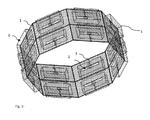
- the first integral part are the electromagnetic field generating elements, figure 1 , which are arranged into an array of arbitrary geometry, figure 2 .
- the array of elements is connected to a radio frequency power source, figure 3 , which has a number of independently phase and amplitude computer controllable channels.
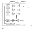
- Integrated into each electromagnetic field generating element is a current (or field) sensing element which produces an electrical output proportional to the electromagnetic field generated, each electrical signal is measured by a measurement device that measures both amplitude and phase, figure 4 .
- the measurement data is communicated via a measurement bus to a measurement controller.
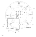
- a control computer utilizes the measurement data to control the radio frequency power source in such a way that the electromagnetic fields generated are the required fields, the whole system and the interconnections are shown in figure 5 .
- An illustrative application of the invention is a phased array 19 applicator system, figure 5 , that can generate specific field conditions at certain locations in space or focus the RF energy into dielectric objects.
- the direct measurement of the currents or fields in metallic, slot or coil elements 26 allows direct quantification of the radiated or reactive fields generated by the electromagnetic field generating elements. More specifically, the invention provides the possibility to implicitly correct for the perturbations in the electromagnetic field generated due mutual coupling and mismatch in the applicator array 19 without explicitly measuring the coupling matrix and applying a correction to the excitations from the a radio frequency power source 18.
- the direct relationship between the current in a metallic element (or field in a slot based element) to the electrical output from the element sensors 4 to the radiated or reactive field can be determined by experimental or numerical means.
- An objective of the invention is to provide an improved means of determining the actual radiated or reactive near field of each element 26, figure 1 , in an array of electromagnetic field generating elements 19 for radio frequency hyperthermia applications, figures 2 and 6 , where the immediate load due to patient, dielectric objects and other system components changes the coupling between and matching seen at the input ports 3 of the elements 26 or where the source impedance of the radio frequency power source channels 11 are not well characterized.
- a further objective of the invention is to provide higher levels of confidence that the real array excitation from the multichannel radio frequency power source 18 is the planned excitation ensuring higher quality control of the field distribution generated by the array 19 of electromagnetic field generating elements.
- the electromagnetic field generated is measured, figure 4 , using a measurement device such as a vector volt meter or in-phase/quadrature demodulator of sufficient sensitivity. Additional circuitry may be added, as shown in figure 4 , to allow self calibration of the amplitude and phase detectors facilitated by not only distributing the local oscillator via a bus but also a phase reference which can be switched to the input to allow calibration and / or phase ambiguity removal further reducing the uncertainty.
- the invention provides a new paradigm for the correction of array mutual coupling by implicitly measuring the generated electromagnetic field with the mutual coupling and mismatch accounted for.
- the actual and planned excitations have a low deviation in particular in the presence of variations that could not be modeled during treatment planning.
- the invention does not limit the geometry or placement of the applicator array elements 26, figure 2 , around or close to the target area and can be applied to any generic array of electromagnetic field generating elements 19.
- the invention does not limit the geometry or placement of the applicator array elements 26, figure 2 , around or close to the target area and can be applied to any generic array of electromagnetic field generating elements 19.
- the invention allows the coupling matrix (that describes the mismatch and mutual coupling) of the applicator array of electromagnetic field generating elements to be directly determined with greater accuracy than the standard technique of calculating the coupling matrix from the S-parameters and with the convenience of not having to disconnect the applicator array 19 from the radio frequency power source 18, figure 5 , and connect it to a network analyzer.
- the coupling matrix can be determined more accurately as the non-ideal output impedances of each amplifier 10 and connecting cable lengths between radio frequency power source output 11 and electromagnetic field generating element 3 are inherently accounted for.
- the invention whilst providing this very important information on the radiated or reactive field from each element 26 also gives the ability to detect which output channel 11 from the multi channel radio frequency power source 18 has been connected to which electromagnetic field generating element 26 in the array 19 and hence remove the possibility of incorrect connection and the chance of a treatment that is completely in error.
- a calibration facility can therefore provide an accredited calibration that can be attributed to a given element. Enabling the whole array 19 to be modular with replaceable elements 26 and provide 'plug and play' capabilities.
- the preferred embodiment can be described in the context of an RF hyperthermia applicator system, figures 5 .
- This hyperthermia applicator system consists of both hardware and a computer control systems and these systems allow enhanced use paradigms that illustrate the utility of the invention.
- the Hyperthermia applicator system illustrated in figure 5 takes the form of a ring array applicator made up of electromagnetic field generating elements, figure 2 , where the electromagnetic field generating elements, figure 1 , are placed around the body in the vicinity of the region to be heated. It is not always the case that elements need to form an entire ring, but might be placed predominantly on one side of the patient. In this specific array however the E-field vector of all elements should be predominantly aligned in the same direction within the target region, but this is not a requirement in all applications of the system.
- the region between the applicator and the patient is filled by a water bolus, figure 6 , of a defined shape which affords three things:
- Cavity backed slot antennas are chosen as the electromagnetic field generating elements in our preferred embodiment as they provide: Low profile, good polarization purity, accurate dimensions through photolithographic printed circuit processing techniques, ease of manufacture, robust structure, relatively broadband response and hence tolerance to environment changes.
- an appropriate method of sensing is through sensing of the field in the slot by means of small coupling loops 4.
- the loops 4 are sufficiently small such that the amount of coupled power is small compared to the total, which could be 100s of Watts, which is applied to the antenna port 3 and so that the field in the slot 2 remains unperturbed by the measurement.
- Each slot element in the applicator is fed from a phase and amplitude controllable radio frequency power source, figure 3 .
- the fields in each applicator element slot due to its own excitation and fields coupled from other elements are sensed 4 and measured using measurement device 20 consisting of a phase / amplitude detectors, figure 4 , and the values communicated to a control system 21.
- measurement device 20 consisting of a phase / amplitude detectors, figure 4
- an in-phase/quadrature demodulator 14 in conjunction with a pair of analog to digital converters 15 is used to measure the in-phase and quadrature voltage levels.
- the digital signal is then converted into a magnitude and phase using the microprocessor 16 and communicated to the measurement controller 21 via a measurement bus 17.
- the control system 22 sets the amplitudes and phases 8 of the multi channel radio frequency power source 18 and measures 20 the resultant fields 4 applied from each element 26 and affords feedback control to ensure the applied fields are the required fields.
- a typical usage paradigm is that a validated numerical electromagnetic model of the applicator array 19 is used with a patient specific EM model derived from CT, MRI or other image data within a treatment planning software.
- the target region or regions for treatment is defined and the optimum ideal excitation values (or non-ideal taking into account mutual coupling and mismatch based on the mutual coupling matrix for the model which may or may not closely correspond to the real coupling matrix due to the possible errors previously mentioned from which the ideal excitation can be calculated) are derived and the corresponding EM-field, SAR or temperature rise values across the whole of the target region or regions generated.
- the target excitations are then transferred to the treatment control software and the patient placed in the applicator 19 at the position modeled in the treatment planning.
- the water bolus 25 is filled with demonized water.
- the measurement devices 20 are put into calibration mode where the RF switch 13 in figure 4 is switched so that the calibration input phase reference signal from the bus 12 is measured by each measurement device to allow calibration of the phase of the device and also to remove the phase ambiguity of the ⁇ 2 quadrature phase splitter in the in-phase/quadrature demodulator 14.
- Each radio frequency power source output 11 channel of the multi channel radio frequency power source 18 is excited in turn to determine which applicator element 26 is connected to each output channel and to measure the fields/currents 4 induced in all the elements to generate the actual mutual coupling matrix for the array 19 at the time of treatment.
- phase and amplitude offset due to the connecting cables or transmit channel differences can be eliminated or calibrated out. Phase shifts due to variation in applicator element impedance from the ideal, for example due to patient proximity and hence change in the dielectric constant immediate environment, are also eliminated.
- Treatment is commenced with radio frequency power 18 being applied to each element 26 based on the treatment planning, either based on ideal or corrected (using the coupling matrix) excitations, the actual excitation levels are determined using the field monitoring 4 and measurement 20 and controlled by the feedback controller 27 to correct for any deviation from the desired excitation levels.
- the total output power from each channel 11 can be controlled 8 and the correct relationship between amplitudes and phase monitored 20 and controlled to the correct value.
Landscapes
- Health & Medical Sciences (AREA)
- Surgery (AREA)
- Life Sciences & Earth Sciences (AREA)
- Biomedical Technology (AREA)
- Medical Informatics (AREA)
- Nuclear Medicine, Radiotherapy & Molecular Imaging (AREA)
- Electromagnetism (AREA)
- Engineering & Computer Science (AREA)
- Physics & Mathematics (AREA)
- Heart & Thoracic Surgery (AREA)
- Otolaryngology (AREA)
- Molecular Biology (AREA)
- Animal Behavior & Ethology (AREA)
- General Health & Medical Sciences (AREA)
- Public Health (AREA)
- Veterinary Medicine (AREA)
- Radiation-Therapy Devices (AREA)
- Electrotherapy Devices (AREA)
Priority Applications (1)
| Application Number | Priority Date | Filing Date | Title |
|---|---|---|---|
| PL11180243T PL2425794T3 (pl) | 2010-09-06 | 2011-09-06 | Układ aplikatora pola elektromagnetycznego ze zintegrowanymi czujnikami pola do niejawnej korekty wzajemnego sprzęgania oraz niedopasowania |
Applications Claiming Priority (1)
| Application Number | Priority Date | Filing Date | Title |
|---|---|---|---|
| CH01439/10A CH704177A2 (de) | 2010-09-06 | 2010-09-06 | Gruppenantennenstruktur zur Erzeugung spezifischer elektromagnetischer Feldverteilungen mit integrierten Sonden zur impliziten Korrektur von gegenseitiger Verkopplung und Fehlanpassung. |
Publications (2)
| Publication Number | Publication Date |
|---|---|
| EP2425794A1 EP2425794A1 (en) | 2012-03-07 |
| EP2425794B1 true EP2425794B1 (en) | 2015-09-02 |
Family
ID=44645100
Family Applications (1)
| Application Number | Title | Priority Date | Filing Date |
|---|---|---|---|
| EP11180243.5A Active EP2425794B1 (en) | 2010-09-06 | 2011-09-06 | Electromagnetic field applicator array with integral field sensors for implicit correction of mutual coupling and mismatch |
Country Status (11)
| Country | Link |
|---|---|
| US (1) | US9763734B2 (pl) |
| EP (1) | EP2425794B1 (pl) |
| JP (1) | JP5925780B2 (pl) |
| CN (1) | CN103200894B (pl) |
| CA (1) | CA2808670A1 (pl) |
| CH (1) | CH704177A2 (pl) |
| DK (1) | DK2425794T3 (pl) |
| ES (1) | ES2552159T3 (pl) |
| PL (1) | PL2425794T3 (pl) |
| PT (1) | PT2425794E (pl) |
| WO (1) | WO2012032053A1 (pl) |
Families Citing this family (16)
| Publication number | Priority date | Publication date | Assignee | Title |
|---|---|---|---|---|
| US9669231B1 (en) * | 2011-11-04 | 2017-06-06 | Parmenides, Inc. | Apparatus and method for hyperthermic treatments |
| US10232188B2 (en) | 2011-11-04 | 2019-03-19 | Thermofield Inc. | Single cable apparatus and method for hyperthermic treatments |
| US11752356B2 (en) * | 2013-03-11 | 2023-09-12 | NeuroEM Therapeutics, Inc. | Systems for controlling power to differently loaded antenna arrays |
| US11759650B2 (en) | 2013-03-11 | 2023-09-19 | NeuroEM Therapeutics, Inc. | Immunoregulation, brain detoxification, and cognitive protection by electromagnetic treatment |
| US11911629B2 (en) | 2013-03-11 | 2024-02-27 | NeurEM Therapeutics, Inc. | Treatment of primary and metastatic brain cancers by transcranial electromagnetic treatment |
| US11813472B2 (en) | 2013-03-11 | 2023-11-14 | NeuroEM Therapeutics, Inc. | Systems for sensing proper emitter array placement |
| US12318624B2 (en) | 2013-03-11 | 2025-06-03 | NeuroEM Therapeutics, Inc. | Brain immunoregulation through transcranial electromagnetic treatment |
| CN103646126A (zh) * | 2013-11-01 | 2014-03-19 | 南京信息工程大学 | 微带阵列聚焦天线的设计方法及微带阵列聚焦天线 |
| US11794028B2 (en) | 2014-03-11 | 2023-10-24 | NeuroEM Therapeutics, Inc. | Transcranial electromagnetic treatment |
| CN106465146B (zh) | 2014-05-05 | 2020-11-03 | 华为技术有限公司 | Rcu和rf端口匹配的电调天线、基站和方法 |
| CN103990228B (zh) * | 2014-05-15 | 2016-02-17 | 哈尔滨易奥秘科技发展有限公司 | 一种可聚焦电磁场的多电极双频谱射频肿瘤热疗仪 |
| KR101676192B1 (ko) * | 2015-10-02 | 2016-11-15 | (의료)길의료재단 | 자기공명영상장치용 다채널 rf 코일 어레이 |
| JP7007360B2 (ja) * | 2016-04-18 | 2022-01-24 | アルプス・サウス・ユーロプ・スポレチノスト・ス・ルチェニーム・オメゼニーム | 誘導加熱器およびディスペンサ |
| CN111939479A (zh) * | 2020-08-20 | 2020-11-17 | 哈尔滨乔然科技有限公司 | 一种相控阵热疗机及其控制方法 |
| CN113456213B (zh) * | 2021-08-13 | 2022-08-02 | 卡本(深圳)医疗器械有限公司 | 一种基于人工智能的射频消融参数优化和信息合成方法及系统 |
| CN119770862B (zh) * | 2024-12-11 | 2025-09-19 | 上海科技大学 | 磁共振引导的聚焦微波脑肿瘤热消融系统与聚焦调整方法 |
Citations (4)
| Publication number | Priority date | Publication date | Assignee | Title |
|---|---|---|---|---|
| US4885589A (en) * | 1988-09-14 | 1989-12-05 | General Electric Company | Optical distribution of transmitter signals and antenna returns in a phased array radar system |
| US20040061644A1 (en) * | 2002-09-11 | 2004-04-01 | Lockheed Martin Corporation | CCE calibration with an array of calibration probes interleaved with the array antenna |
| WO2007146175A2 (en) * | 2006-06-12 | 2007-12-21 | Powerwave Technologies, Inc | Smart antenna array over fiber |
| US20080297402A1 (en) * | 2006-03-22 | 2008-12-04 | Wooldridge John J | Built-in missile radar calibration verification |
Family Cites Families (14)
| Publication number | Priority date | Publication date | Assignee | Title |
|---|---|---|---|---|
| US4798215A (en) | 1984-03-15 | 1989-01-17 | Bsd Medical Corporation | Hyperthermia apparatus |
| US4672980A (en) | 1980-04-02 | 1987-06-16 | Bsd Medical Corporation | System and method for creating hyperthermia in tissue |
| US5441532A (en) | 1991-06-26 | 1995-08-15 | Massachusetts Institute Of Technology | Adaptive focusing and nulling hyperthermia annular and monopole phased array applicators |
| US5251645A (en) | 1991-06-26 | 1993-10-12 | Massachusetts Institute Of Technology | Adaptive nulling hyperthermia array |
| US5769879A (en) | 1995-06-07 | 1998-06-23 | Medical Contouring Corporation | Microwave applicator and method of operation |
| US5867123A (en) | 1997-06-19 | 1999-02-02 | Motorola, Inc. | Phased array radio frequency (RF) built-in-test equipment (BITE) apparatus and method of operation therefor |
| US6904323B2 (en) * | 2003-05-14 | 2005-06-07 | Duke University | Non-invasive apparatus and method for providing RF energy-induced localized hyperthermia |
| US20060265034A1 (en) * | 2005-04-05 | 2006-11-23 | Ams Medical Sa | Microwave devices for treating biological samples and tissue and methods for using same |
| US8700176B2 (en) * | 2006-07-27 | 2014-04-15 | Pollogen Ltd. | Apparatus and method for non-invasive treatment of skin tissue |
| EP1911410A1 (de) * | 2006-10-10 | 2008-04-16 | Wavelight Aesthetic GmbH | Vorrichtung für dermatologische Behandlungen |
| GB0624584D0 (en) * | 2006-12-08 | 2007-01-17 | Medical Device Innovations Ltd | Skin treatment apparatus and method |
| BRPI0810066A2 (pt) * | 2007-04-19 | 2015-05-05 | The Foundry Inc | Sistemas e métodos para criação de um efeito utilizando energia de microondas à tecido específico |
| US20080281386A1 (en) * | 2007-05-09 | 2008-11-13 | Tessaron Medical, Inc. | Systems and methods for treating body tissue |
| US9415234B2 (en) * | 2012-07-06 | 2016-08-16 | Pyrexar Medical Inc. | Tissue heating prediction using feedpoint EM field determination |
-
2010
- 2010-09-06 CH CH01439/10A patent/CH704177A2/de not_active Application Discontinuation
-
2011
- 2011-09-06 CN CN201180053379.7A patent/CN103200894B/zh active Active
- 2011-09-06 CA CA2808670A patent/CA2808670A1/en not_active Abandoned
- 2011-09-06 WO PCT/EP2011/065402 patent/WO2012032053A1/en not_active Ceased
- 2011-09-06 EP EP11180243.5A patent/EP2425794B1/en active Active
- 2011-09-06 PL PL11180243T patent/PL2425794T3/pl unknown
- 2011-09-06 PT PT111802435T patent/PT2425794E/pt unknown
- 2011-09-06 ES ES11180243.5T patent/ES2552159T3/es active Active
- 2011-09-06 US US13/261,600 patent/US9763734B2/en active Active
- 2011-09-06 JP JP2013526511A patent/JP5925780B2/ja active Active
- 2011-09-06 DK DK11180243.5T patent/DK2425794T3/en active
Patent Citations (4)
| Publication number | Priority date | Publication date | Assignee | Title |
|---|---|---|---|---|
| US4885589A (en) * | 1988-09-14 | 1989-12-05 | General Electric Company | Optical distribution of transmitter signals and antenna returns in a phased array radar system |
| US20040061644A1 (en) * | 2002-09-11 | 2004-04-01 | Lockheed Martin Corporation | CCE calibration with an array of calibration probes interleaved with the array antenna |
| US20080297402A1 (en) * | 2006-03-22 | 2008-12-04 | Wooldridge John J | Built-in missile radar calibration verification |
| WO2007146175A2 (en) * | 2006-06-12 | 2007-12-21 | Powerwave Technologies, Inc | Smart antenna array over fiber |
Also Published As
| Publication number | Publication date |
|---|---|
| PT2425794E (pt) | 2015-12-24 |
| US20130237742A1 (en) | 2013-09-12 |
| CN103200894B (zh) | 2017-06-13 |
| EP2425794A1 (en) | 2012-03-07 |
| CN103200894A (zh) | 2013-07-10 |
| JP5925780B2 (ja) | 2016-05-25 |
| DK2425794T3 (en) | 2015-11-09 |
| ES2552159T3 (es) | 2015-11-26 |
| CA2808670A1 (en) | 2012-03-15 |
| CH704177A2 (de) | 2012-05-31 |
| US9763734B2 (en) | 2017-09-19 |
| WO2012032053A1 (en) | 2012-03-15 |
| JP2013538612A (ja) | 2013-10-17 |
| PL2425794T3 (pl) | 2016-07-29 |
Similar Documents
| Publication | Publication Date | Title |
|---|---|---|
| EP2425794B1 (en) | Electromagnetic field applicator array with integral field sensors for implicit correction of mutual coupling and mismatch | |
| US8319496B2 (en) | Magnetic resonance method and apparatus for reducing RF heating in the patient | |
| US11839449B2 (en) | Real-time imaging system for monitoring and control of thermal therapy treatments | |
| US9415234B2 (en) | Tissue heating prediction using feedpoint EM field determination | |
| EP2382934B1 (en) | Measurement and control systems for electrosurgical procedures | |
| US8502546B2 (en) | Multichannel absorberless near field measurement system | |
| US20110316539A1 (en) | Antenna array comprising at least one dipole antenna for magnetic resonance imaging | |
| WO2009046516A1 (en) | Multichannel absorberless near field measurement system | |
| EP2126600B1 (en) | A model based positioning system | |
| Eigentler et al. | Wideband self‐grounded bow‐tie antenna for thermal mr | |
| van Leeuwen et al. | The coax dipole: a fully flexible coaxial cable dipole antenna with flattened current distribution for body imaging at 7 Tesla | |
| Bakker et al. | Design and test of a 434 MHz multi-channel amplifier system for targeted hyperthermia applicators | |
| Restivo et al. | Improving peak local SAR prediction in parallel transmit using in situ S‐matrix measurements | |
| Sun et al. | A retrofit to enable dynamic steering for transmit arrays without multiple amplifiers | |
| WO2007112546A1 (en) | Multichannel absorberless near field measurement system | |
| Behnia et al. | Closed‐loop feedback control of phased‐array microwave heating using thermal measurements from magnetic resonance imaging | |
| Sumser et al. | Dual-function MR-guided hyperthermia: An innovative integrated approach and experimental demonstration of proof of principle | |
| Capstick et al. | Novel applicator for local RF hyperthermia treatment using improved excitation control | |
| Raskmark et al. | Multi-applicator hyperthermia system description using scattering parameters | |
| Wust et al. | Scanning E-field sensor device for online measurements in annular phased-array systems | |
| US20220187391A1 (en) | Multi-frequency high electric field systems for magnetic resonance imaging safety testing of medical devices | |
| Han et al. | Multi-Channel RF Supervision Module for Thermal Magnetic Resonance Based Cancer Therapy. Cancers 2021, 13, 1001 | |
| Behnia et al. | MRI‐monitored electromagnetic heating using iterative feedback control and phase interference mapping | |
| KR20250110990A (ko) | Mr 영상용 복합 패치 안테나 | |
| Wlodarczyk et al. | RF hyperthermia: modeling and clinical systems |
Legal Events
| Date | Code | Title | Description |
|---|---|---|---|
| AK | Designated contracting states |
Kind code of ref document: A1 Designated state(s): AL AT BE BG CH CY CZ DE DK EE ES FI FR GB GR HR HU IE IS IT LI LT LU LV MC MK MT NL NO PL PT RO RS SE SI SK SM TR |
|
| AX | Request for extension of the european patent |
Extension state: BA ME |
|
| PUAI | Public reference made under article 153(3) epc to a published international application that has entered the european phase |
Free format text: ORIGINAL CODE: 0009012 |
|
| 17P | Request for examination filed |
Effective date: 20120822 |
|
| 17Q | First examination report despatched |
Effective date: 20130626 |
|
| GRAP | Despatch of communication of intention to grant a patent |
Free format text: ORIGINAL CODE: EPIDOSNIGR1 |
|
| INTG | Intention to grant announced |
Effective date: 20150317 |
|
| GRAS | Grant fee paid |
Free format text: ORIGINAL CODE: EPIDOSNIGR3 |
|
| GRAA | (expected) grant |
Free format text: ORIGINAL CODE: 0009210 |
|
| AK | Designated contracting states |
Kind code of ref document: B1 Designated state(s): AL AT BE BG CH CY CZ DE DK EE ES FI FR GB GR HR HU IE IS IT LI LT LU LV MC MK MT NL NO PL PT RO RS SE SI SK SM TR |
|
| REG | Reference to a national code |
Ref country code: GB Ref legal event code: FG4D |
|
| REG | Reference to a national code |
Ref country code: AT Ref legal event code: REF Ref document number: 746041 Country of ref document: AT Kind code of ref document: T Effective date: 20150915 Ref country code: CH Ref legal event code: EP |
|
| REG | Reference to a national code |
Ref country code: IE Ref legal event code: FG4D |
|
| REG | Reference to a national code |
Ref country code: DE Ref legal event code: R096 Ref document number: 602011019324 Country of ref document: DE |
|
| REG | Reference to a national code |
Ref country code: FR Ref legal event code: PLFP Year of fee payment: 5 |
|
| REG | Reference to a national code |
Ref country code: DK Ref legal event code: T3 Effective date: 20151103 |
|
| REG | Reference to a national code |
Ref country code: ES Ref legal event code: FG2A Ref document number: 2552159 Country of ref document: ES Kind code of ref document: T3 Effective date: 20151126 |
|
| REG | Reference to a national code |
Ref country code: SE Ref legal event code: TRGR |
|
| REG | Reference to a national code |
Ref country code: PT Ref legal event code: SC4A Free format text: AVAILABILITY OF NATIONAL TRANSLATION Effective date: 20151130 |
|
| REG | Reference to a national code |
Ref country code: CH Ref legal event code: PK Free format text: BERICHTIGUNG INHABER Ref country code: CH Ref legal event code: NV Representative=s name: SCHMAUDER AND PARTNER AG PATENT- UND MARKENANW, CH |
|
| PG25 | Lapsed in a contracting state [announced via postgrant information from national office to epo] |
Ref country code: LV Free format text: LAPSE BECAUSE OF FAILURE TO SUBMIT A TRANSLATION OF THE DESCRIPTION OR TO PAY THE FEE WITHIN THE PRESCRIBED TIME-LIMIT Effective date: 20150902 Ref country code: GR Free format text: LAPSE BECAUSE OF FAILURE TO SUBMIT A TRANSLATION OF THE DESCRIPTION OR TO PAY THE FEE WITHIN THE PRESCRIBED TIME-LIMIT Effective date: 20151203 Ref country code: LT Free format text: LAPSE BECAUSE OF FAILURE TO SUBMIT A TRANSLATION OF THE DESCRIPTION OR TO PAY THE FEE WITHIN THE PRESCRIBED TIME-LIMIT Effective date: 20150902 |
|
| REG | Reference to a national code |
Ref country code: NL Ref legal event code: FP |
|
| REG | Reference to a national code |
Ref country code: LT Ref legal event code: MG4D |
|
| PG25 | Lapsed in a contracting state [announced via postgrant information from national office to epo] |
Ref country code: RS Free format text: LAPSE BECAUSE OF FAILURE TO SUBMIT A TRANSLATION OF THE DESCRIPTION OR TO PAY THE FEE WITHIN THE PRESCRIBED TIME-LIMIT Effective date: 20150902 |
|
| PG25 | Lapsed in a contracting state [announced via postgrant information from national office to epo] |
Ref country code: IS Free format text: LAPSE BECAUSE OF FAILURE TO SUBMIT A TRANSLATION OF THE DESCRIPTION OR TO PAY THE FEE WITHIN THE PRESCRIBED TIME-LIMIT Effective date: 20160102 Ref country code: CZ Free format text: LAPSE BECAUSE OF FAILURE TO SUBMIT A TRANSLATION OF THE DESCRIPTION OR TO PAY THE FEE WITHIN THE PRESCRIBED TIME-LIMIT Effective date: 20150902 Ref country code: EE Free format text: LAPSE BECAUSE OF FAILURE TO SUBMIT A TRANSLATION OF THE DESCRIPTION OR TO PAY THE FEE WITHIN THE PRESCRIBED TIME-LIMIT Effective date: 20150902 Ref country code: SK Free format text: LAPSE BECAUSE OF FAILURE TO SUBMIT A TRANSLATION OF THE DESCRIPTION OR TO PAY THE FEE WITHIN THE PRESCRIBED TIME-LIMIT Effective date: 20150902 |
|
| PG25 | Lapsed in a contracting state [announced via postgrant information from national office to epo] |
Ref country code: RO Free format text: LAPSE BECAUSE OF FAILURE TO SUBMIT A TRANSLATION OF THE DESCRIPTION OR TO PAY THE FEE WITHIN THE PRESCRIBED TIME-LIMIT Effective date: 20150902 |
|
| REG | Reference to a national code |
Ref country code: DE Ref legal event code: R097 Ref document number: 602011019324 Country of ref document: DE |
|
| PG25 | Lapsed in a contracting state [announced via postgrant information from national office to epo] |
Ref country code: MC Free format text: LAPSE BECAUSE OF FAILURE TO SUBMIT A TRANSLATION OF THE DESCRIPTION OR TO PAY THE FEE WITHIN THE PRESCRIBED TIME-LIMIT Effective date: 20150902 |
|
| PLBE | No opposition filed within time limit |
Free format text: ORIGINAL CODE: 0009261 |
|
| STAA | Information on the status of an ep patent application or granted ep patent |
Free format text: STATUS: NO OPPOSITION FILED WITHIN TIME LIMIT |
|
| REG | Reference to a national code |
Ref country code: NO Ref legal event code: T2 Effective date: 20150902 |
|
| 26N | No opposition filed |
Effective date: 20160603 |
|
| PG25 | Lapsed in a contracting state [announced via postgrant information from national office to epo] |
Ref country code: SI Free format text: LAPSE BECAUSE OF FAILURE TO SUBMIT A TRANSLATION OF THE DESCRIPTION OR TO PAY THE FEE WITHIN THE PRESCRIBED TIME-LIMIT Effective date: 20150902 |
|
| REG | Reference to a national code |
Ref country code: FR Ref legal event code: PLFP Year of fee payment: 6 |
|
| REG | Reference to a national code |
Ref country code: DE Ref legal event code: R082 Ref document number: 602011019324 Country of ref document: DE Representative=s name: REBLE & KESSELHUT PARTNERSCHAFTSGESELLSCHAFT V, DE |
|
| PG25 | Lapsed in a contracting state [announced via postgrant information from national office to epo] |
Ref country code: MT Free format text: LAPSE BECAUSE OF FAILURE TO SUBMIT A TRANSLATION OF THE DESCRIPTION OR TO PAY THE FEE WITHIN THE PRESCRIBED TIME-LIMIT Effective date: 20150902 |
|
| PG25 | Lapsed in a contracting state [announced via postgrant information from national office to epo] |
Ref country code: HU Free format text: LAPSE BECAUSE OF FAILURE TO SUBMIT A TRANSLATION OF THE DESCRIPTION OR TO PAY THE FEE WITHIN THE PRESCRIBED TIME-LIMIT; INVALID AB INITIO Effective date: 20110906 Ref country code: BG Free format text: LAPSE BECAUSE OF FAILURE TO SUBMIT A TRANSLATION OF THE DESCRIPTION OR TO PAY THE FEE WITHIN THE PRESCRIBED TIME-LIMIT Effective date: 20150902 Ref country code: SM Free format text: LAPSE BECAUSE OF FAILURE TO SUBMIT A TRANSLATION OF THE DESCRIPTION OR TO PAY THE FEE WITHIN THE PRESCRIBED TIME-LIMIT Effective date: 20150902 |
|
| PG25 | Lapsed in a contracting state [announced via postgrant information from national office to epo] |
Ref country code: CY Free format text: LAPSE BECAUSE OF FAILURE TO SUBMIT A TRANSLATION OF THE DESCRIPTION OR TO PAY THE FEE WITHIN THE PRESCRIBED TIME-LIMIT Effective date: 20150902 |
|
| PG25 | Lapsed in a contracting state [announced via postgrant information from national office to epo] |
Ref country code: HR Free format text: LAPSE BECAUSE OF FAILURE TO SUBMIT A TRANSLATION OF THE DESCRIPTION OR TO PAY THE FEE WITHIN THE PRESCRIBED TIME-LIMIT Effective date: 20150902 |
|
| PG25 | Lapsed in a contracting state [announced via postgrant information from national office to epo] |
Ref country code: TR Free format text: LAPSE BECAUSE OF FAILURE TO SUBMIT A TRANSLATION OF THE DESCRIPTION OR TO PAY THE FEE WITHIN THE PRESCRIBED TIME-LIMIT Effective date: 20150902 |
|
| REG | Reference to a national code |
Ref country code: FR Ref legal event code: PLFP Year of fee payment: 7 |
|
| PGFP | Annual fee paid to national office [announced via postgrant information from national office to epo] |
Ref country code: FI Payment date: 20170922 Year of fee payment: 7 Ref country code: NO Payment date: 20170925 Year of fee payment: 7 |
|
| PG25 | Lapsed in a contracting state [announced via postgrant information from national office to epo] |
Ref country code: LU Free format text: LAPSE BECAUSE OF NON-PAYMENT OF DUE FEES Effective date: 20150906 |
|
| PGFP | Annual fee paid to national office [announced via postgrant information from national office to epo] |
Ref country code: IE Payment date: 20170928 Year of fee payment: 7 Ref country code: DK Payment date: 20170921 Year of fee payment: 7 Ref country code: PT Payment date: 20170901 Year of fee payment: 7 Ref country code: SE Payment date: 20170921 Year of fee payment: 7 Ref country code: PL Payment date: 20170901 Year of fee payment: 7 |
|
| REG | Reference to a national code |
Ref country code: AT Ref legal event code: UEP Ref document number: 746041 Country of ref document: AT Kind code of ref document: T Effective date: 20150902 |
|
| PG25 | Lapsed in a contracting state [announced via postgrant information from national office to epo] |
Ref country code: MK Free format text: LAPSE BECAUSE OF FAILURE TO SUBMIT A TRANSLATION OF THE DESCRIPTION OR TO PAY THE FEE WITHIN THE PRESCRIBED TIME-LIMIT Effective date: 20150902 |
|
| REG | Reference to a national code |
Ref country code: FR Ref legal event code: PLFP Year of fee payment: 8 |
|
| PG25 | Lapsed in a contracting state [announced via postgrant information from national office to epo] |
Ref country code: AL Free format text: LAPSE BECAUSE OF FAILURE TO SUBMIT A TRANSLATION OF THE DESCRIPTION OR TO PAY THE FEE WITHIN THE PRESCRIBED TIME-LIMIT Effective date: 20150902 |
|
| REG | Reference to a national code |
Ref country code: NO Ref legal event code: MMEP |
|
| PG25 | Lapsed in a contracting state [announced via postgrant information from national office to epo] |
Ref country code: FI Free format text: LAPSE BECAUSE OF NON-PAYMENT OF DUE FEES Effective date: 20180906 |
|
| REG | Reference to a national code |
Ref country code: SE Ref legal event code: EUG |
|
| REG | Reference to a national code |
Ref country code: DK Ref legal event code: EBP Effective date: 20180930 |
|
| PG25 | Lapsed in a contracting state [announced via postgrant information from national office to epo] |
Ref country code: SE Free format text: LAPSE BECAUSE OF NON-PAYMENT OF DUE FEES Effective date: 20180907 Ref country code: PT Free format text: LAPSE BECAUSE OF NON-PAYMENT OF DUE FEES Effective date: 20190306 |
|
| REG | Reference to a national code |
Ref country code: IE Ref legal event code: MM4A |
|
| PG25 | Lapsed in a contracting state [announced via postgrant information from national office to epo] |
Ref country code: NO Free format text: LAPSE BECAUSE OF NON-PAYMENT OF DUE FEES Effective date: 20180930 Ref country code: IE Free format text: LAPSE BECAUSE OF NON-PAYMENT OF DUE FEES Effective date: 20180906 |
|
| PG25 | Lapsed in a contracting state [announced via postgrant information from national office to epo] |
Ref country code: DK Free format text: LAPSE BECAUSE OF NON-PAYMENT OF DUE FEES Effective date: 20180930 |
|
| PGFP | Annual fee paid to national office [announced via postgrant information from national office to epo] |
Ref country code: NL Payment date: 20190918 Year of fee payment: 9 |
|
| PGFP | Annual fee paid to national office [announced via postgrant information from national office to epo] |
Ref country code: BE Payment date: 20190918 Year of fee payment: 9 |
|
| PGFP | Annual fee paid to national office [announced via postgrant information from national office to epo] |
Ref country code: AT Payment date: 20190919 Year of fee payment: 9 |
|
| PGFP | Annual fee paid to national office [announced via postgrant information from national office to epo] |
Ref country code: ES Payment date: 20191022 Year of fee payment: 9 |
|
| PG25 | Lapsed in a contracting state [announced via postgrant information from national office to epo] |
Ref country code: PL Free format text: LAPSE BECAUSE OF NON-PAYMENT OF DUE FEES Effective date: 20180906 |
|
| REG | Reference to a national code |
Ref country code: NL Ref legal event code: MM Effective date: 20201001 |
|
| REG | Reference to a national code |
Ref country code: AT Ref legal event code: MM01 Ref document number: 746041 Country of ref document: AT Kind code of ref document: T Effective date: 20200906 |
|
| REG | Reference to a national code |
Ref country code: BE Ref legal event code: MM Effective date: 20200930 |
|
| PG25 | Lapsed in a contracting state [announced via postgrant information from national office to epo] |
Ref country code: NL Free format text: LAPSE BECAUSE OF NON-PAYMENT OF DUE FEES Effective date: 20201001 |
|
| PG25 | Lapsed in a contracting state [announced via postgrant information from national office to epo] |
Ref country code: BE Free format text: LAPSE BECAUSE OF NON-PAYMENT OF DUE FEES Effective date: 20200930 Ref country code: AT Free format text: LAPSE BECAUSE OF NON-PAYMENT OF DUE FEES Effective date: 20200906 |
|
| REG | Reference to a national code |
Ref country code: ES Ref legal event code: FD2A Effective date: 20220114 |
|
| PG25 | Lapsed in a contracting state [announced via postgrant information from national office to epo] |
Ref country code: ES Free format text: LAPSE BECAUSE OF NON-PAYMENT OF DUE FEES Effective date: 20200907 |
|
| REG | Reference to a national code |
Ref country code: CH Ref legal event code: U11 Free format text: ST27 STATUS EVENT CODE: U-0-0-U10-U11 (AS PROVIDED BY THE NATIONAL OFFICE) Effective date: 20251001 |
|
| PGFP | Annual fee paid to national office [announced via postgrant information from national office to epo] |
Ref country code: DE Payment date: 20250919 Year of fee payment: 15 |
|
| PGFP | Annual fee paid to national office [announced via postgrant information from national office to epo] |
Ref country code: IT Payment date: 20250923 Year of fee payment: 15 |
|
| PGFP | Annual fee paid to national office [announced via postgrant information from national office to epo] |
Ref country code: GB Payment date: 20250918 Year of fee payment: 15 |
|
| PGFP | Annual fee paid to national office [announced via postgrant information from national office to epo] |
Ref country code: FR Payment date: 20250922 Year of fee payment: 15 |
|
| REG | Reference to a national code |
Ref country code: DE Ref legal event code: R082 Ref document number: 602011019324 Country of ref document: DE Representative=s name: KESSELHUT, WOLF, DIPL.-PHYS., DE |
|
| PGFP | Annual fee paid to national office [announced via postgrant information from national office to epo] |
Ref country code: CH Payment date: 20251001 Year of fee payment: 15 |