EP2425686B1 - Particle beam target with improved heat transfer and related method - Google Patents
Particle beam target with improved heat transfer and related method Download PDFInfo
- Publication number
- EP2425686B1 EP2425686B1 EP09844184.3A EP09844184A EP2425686B1 EP 2425686 B1 EP2425686 B1 EP 2425686B1 EP 09844184 A EP09844184 A EP 09844184A EP 2425686 B1 EP2425686 B1 EP 2425686B1
- Authority
- EP
- European Patent Office
- Prior art keywords
- target
- coolant
- peripheral
- bore
- bores
- Prior art date
- Legal status (The legal status is an assumption and is not a legal conclusion. Google has not performed a legal analysis and makes no representation as to the accuracy of the status listed.)
- Active
Links
Images


Classifications
-
- H—ELECTRICITY
- H05—ELECTRIC TECHNIQUES NOT OTHERWISE PROVIDED FOR
- H05H—PLASMA TECHNIQUE; PRODUCTION OF ACCELERATED ELECTRICALLY-CHARGED PARTICLES OR OF NEUTRONS; PRODUCTION OR ACCELERATION OF NEUTRAL MOLECULAR OR ATOMIC BEAMS
- H05H6/00—Targets for producing nuclear reactions
Definitions
- the present invention relates generally to particle beam targets utilized for producing radionuclides. More particularly, the present invention relates to the cooling of targets during irradiation by a particle beam.
- Radionuclides may be produced by bombarding a target with an accelerated particle beam as may be generated by a cyclotron, linear accelerator, or the like.
- the target contains a small amount of target material that is typically provided in the liquid phase but could also be a solid or gas.
- the target material includes a precursor component that is synthesized to the desired radionuclide in reaction to irradiation by the particle beam.
- F-18 ions may be produced by bombarding a target containing water enriched with the 0-18 isotope with a proton beam. After bombardment, the as-synthesized F-18 ions may be recovered from the water after removing the water from the target. The production of F-18 ions in particular has important radiopharmaceutical applications.
- the as-produced F-18 ions may be utilized to produce the radioactive sugar fluorodeoxyglucose (2-fluoro-2-deoxy-D-glucose, or FDG), which is utilized in positron emission tomography (PET) scanning.
- FDG radioactive sugar fluorodeoxyglucose
- PET positron emission tomography
- radionuclides such as F-18 ions
- the production of radionuclides is an expensive process, and thus any improvement to the production efficiency and yield would be desirable.
- the application of the particle beam initiates the desired nuclear reaction in only a very small fraction of the radionuclide precursors in the target.
- the particle beam deposits a significant amount of heat into the target material residing in the target during bombardment.
- the amount of radioactive product that can be produced in a radionuclide target is proportional to the amount of heat that can be removed during bombardment of the target material of choice.
- the rapidly increasing vapor pressure developed in the target chamber containing the target material as a result of the heat deposition may cause the target to structurally fail if the heat deposition is not adequately removed.
- Radionuclide production yield could be increased by increasing the beam energy inputted to the target, but due to the foregoing problems the beam energy has been intentionally limited in conventional systems.
- Conventional radionuclide production systems may provide a means for cooling the beam targets generally by routing a heat transfer medium such as water to the target to carry heat away therefrom during bombardment.
- Conventional target designs do not have sufficient capacity for heat removal, and as a result the radionuclide production yield and efficiency has been less than desirable in conventional targets.
- WO 2008/073468 A1 relates to a system and method provided for reclaiming an enriched radioisotope starting material from a target body.
- a chemical protective layer is disposed between a radioisotope starting material and a base material of the target body. After the target body is irradiated, the irradiated radioisotope starting material can be removed without removing the base material due to the protection provided by the chemical protective layer.
- the target body has the protective layers and has at its backside a hollow chamber being a coolant passage which in turn has tubular openings to the backside thereof. The tubular openings extend at the backside from the target body through the hollow chamber.
- the tubular openings may be connected internally within the base layer such that a channel is formed between the two tubular openings.
- coolant may enter through opening into the coolant passage disposed therebetween and exit the hollow chamber via opening back to the coolant source.
- Grooves disposed on the backside of the target body are configured to increase the surface area of the target body, thereby improving heat transfer from the target to the coolant.
- the present invention defines a particle beam target according to claim 1 as well as a method for cooling a particle beam target according to claim 13. Particular embodiments of the present invention are defined in the dependent claims.
- Figures 1-13 illustrate various implementations of a target and associated radionuclide production apparatus or system.
- the various implementations provide a highly efficient solution for cooling a target cavity containing target material bombarded by particles (e.g., protons) for the purpose of obtaining a maximum amount of heat removal from the target material and thereby maximizing the amount of radioactive product that can be produced from that target material.
- the amount of radioactive product that can be produced in a radionuclide target is proportional to the amount of heat that can be removed during bombardment of the target material of choice.
- a high rate of heat removal is accomplished at least in part by providing numerous individual, high-velocity, multi-stage coolant flow paths arranged in parallel and closely spaced to each other ad in close proximity to the target cavity containing the target material to be cooled.
- This configuration maximizes the heat flow from the target medium to the coolant by minimizing the heat conduction distance (i.e., the thickness of the target structure across which the heat must be transferred).
- the target may be implemented in connection with any type of liquid coolant and any type of radionuclide synthesis process.
- a target consistent with the present teaching has experimentally demonstrated superior performance in transferring heat away from target material, as compared to conventional targets.
- FIG. 1 is a simplified schematic view of an example of a radionuclide production apparatus or system 100 as an example of an operating environment in which a target 102 according to the present teachings may be implemented.
- the target 102 generally includes a front side (beam input side) 112 at which a particle beam 114 is directed and a back side (coolant input side) 116 which, in the presently described implementation, receives an input of any suitable liquid coolant (e.g., water).
- the target 102 also generally includes a target body that may include one or more parts assembled together. Insofar as the target 102 may include assembled components, the target 102 may also be referred to herein as a target assembly.
- the target 102 is typically constructed from a suitable metal or metal alloy, a few examples being silver, aluminum, gold, nickel, titanium, copper, platinum, tantalum, niobium, and stainless steel.
- the target 102 includes a target window 118 of any material suitable for transmitting the particle beam 114 therethrough while minimizing loss of beam energy.
- the target window 118 is constructed from a metal or metal alloy, a few examples being the commercially available HAVAR® alloy, titanium, tantalum, tungsten, and gold.
- the thickness of the target window 118 may range, for example, from 0.3 to 30 ⁇ m.
- a target chamber or cavity 120 is formed within the target body and defines an interior of the target body into which the particle beam 114 is directed via the target window 118 .
- the target cavity 120 contains a flowable target material that includes a radionuclide precursor, the composition of which will depend on the type of radionuclide being synthesized.
- the internal volume (or size) of the target cavity 120 may range from 1.0 to 10 cm 3 .
- a coolant inlet 122 and a coolant outlet 124 are also formed in the target body. The coolant inlet 122 and the coolant outlet 124 communicate with each other via a coolant flow system internal to the target body, as described in more detail below.
- the volume of the target cavity 120 after assembly of the target window 118 thereto ranges from 0.5 cc (or ml) to 20 cc. In other non-limiting examples, particularly where the target material is a solid, the volume of the target cavity 120 after assembly of the target window 118 thereto ranges from 0.1 cc to 20 cc. In other non-limiting examples, particularly where the target material is a gas, the volume of the target cavity 120 after assembly of the target window 118 thereto ranges from 100 cc to 10,000 cc (10 L).
- One or more target material transfer bores may be formed in the target 102 for inputting target material into and/or outputting target material from the target cavity 120.
- a target material inlet bore 132 and a separate target material outlet bore 134 are formed in the target body and fluidly communicate with the target cavity 120.
- the locations of the inlet bore 132 and the outlet bore 134 are arbitrary in the schematic view of the Figure 1 , and may depend on whether it is desired to load the target 102 with target material from the top or the bottom.
- the inlet bore 132 may alternatively be located at the top of the target cavity 120 and the outlet bore 134 may be located at the bottom of the target cavity 120.
- the target 102 may include a single bore 132 or 134 utilized for both introducing target material (including precursors) to the target cavity 120 and removing target material (including radionuclides) from the target cavity 120 .
- a single fluid transfer bore 132 or 134 or both an inlet bore 132 and an outlet bore 134 is directed primarily to the use of a liquid target material. It will be appreciated by persons skilled in the art that in other cases, such as where the target material is a solid or a gas, the inlet bore 132 and/or outlet bore 134 may be modified as necessary or not utilized at all.
- molten target material could first be loaded into the target cavity 120 and allowed to solidify, and the target material is maintained in the solid phase during application of the particle beam due to the cooling provided by the present teachings.
- the radionuclide production apparatus 100 includes a particle beam source 140 such as, for example, a cyclotron, a linear accelerator, or the like.
- the structure and operation of the particle beam source 140 may depend on the type of particle beam 114 utilized.
- the particle beam 114 may be a proton beam.
- the proton beam is typically applied at a beam power of about 0.5 kW or greater, up to a practical limit that avoids structural failure of the target 102 and impairment of the desired nuclear reaction. In conventional targets, the beam power typically does not exceed about 2 kW. In at least some implementations of the target 102 taught herein, it is expected that the beam power may be increased to about 10 kW or greater.
- the radionuclide production apparatus 100 also includes a target material transport circuit or system 150.
- the target material transport system 150 may include any suitable target material source (supply, reservoir, etc.) 152 , a device for moving the target material such as, for example, a pump 154 , and a target material input line 156 for conducting the target material from the target material source 152 to the inlet bore 132 and thus the target cavity 120.
- the target material transport system 150 may be implemented as a loop, in which case the above-noted outlet bore 134 is included as well as a target material output line 158 that leads back to the target material source 152 or at least back to the pump 154 .
- the target material may be flowed through the inlet bore 132 , filling the target cavity 120 , and through the outlet bore 134 prior to activation of the particle beam 114.
- the target material transport system 150 may be utilized to purge the target cavity 120 of bubbles, gases, contaminants, or any other undesired components prior to application of the particle beam 114 and ensuing synthesis.
- the target cavity 120 may be filled from the top (in which case the inlet bore 132 may be located at the top, as in the illustrated example) or from the bottom (in which case the inlet bore 132 may be located at the bottom).
- the schematically illustrated positions of the target material source 152 and the pump 154 may be switched as needed for top-filling or bottom-filling.
- the target material transport system 150 may also be utilized to route as-produced radionuclides to a desired radionuclide destination 162 for further processing, such as a hot lab.
- a radionuclide output line 164 is schematically shown as fluidly communicating with the target material outlet line 158 (or, alternatively, with the target material inlet line 156 ).
- a valve or other controllable flow-diverting means may serve as an interface between the target material transport system 150 and the radionuclide output line 164 for this purpose.
- the radionuclide production apparatus 100 also includes a coolant circulation circuit or system 170.
- the coolant circulation system 170 may include any suitable coolant conditioning apparatus (heat exchanger, condenser, evaporator, and the like) 172 for providing coolant to the target 102, receiving heated coolant from the target 102, removing heat from the heated coolant, and repeating the cycle as needed during synthesis.
- suitable coolant conditioning apparatus heat exchanger, condenser, evaporator, and the like
- the coolant circulation system 170 may also include a device for moving the coolant to and from the target 102 such as, for example, a pump 174, a coolant input line 176 for conducting the coolant from the coolant conditioning apparatus 172 to the coolant inlet 122 of the target 102, and a coolant output line 178 for conducting the heated coolant from the coolant outlet 124 of target 102 back to the coolant conditioning apparatus 172.
- a device for moving the coolant to and from the target 102 such as, for example, a pump 174, a coolant input line 176 for conducting the coolant from the coolant conditioning apparatus 172 to the coolant inlet 122 of the target 102, and a coolant output line 178 for conducting the heated coolant from the coolant outlet 124 of target 102 back to the coolant conditioning apparatus 172.
- the target material source 152 is provided with a suitable supply of target material, and the target cavity 120 is loaded with a suitable amount of target material by flowing the target material from the target material source 152 into the target cavity 120 .
- the particle beam source 140 is operated to generate a particle beam 114, which is directed into the target cavity 120 via the target window 118 for interaction with the target material.
- Application of the particle beam 114 results in synthesis of radionuclides from the target material in the target cavity 120.
- the particle beam 114 is switched off and the as-produced radionuclides are transported to the hot lab or other destination 162 for further processing.
- the particle beam 114 a large amount of energy is deposited as heat in the target material residing in the target cavity 120. This heat generates a large amount of vapor within the target cavity 120 resulting in voids or bubbles within the target material.
- the voids or bubbles interfere with the particle beam's ability to cause the nuclear reaction needed for radionuclide synthesis, and the vapor pressure may quickly cause the target 102 to fail structurally.
- the heat must be rapidly removed from the target 102 and from the target material residing in the target 102. This is accomplished through the operation of the coolant circulation system 170 during application of the particle beam 114 in conjunction with a coolant circulation system incorporated into the target 102 , as described by way of examples below.
- radionuclide synthesis is the production of the F-18 ( 18 F - ) ion (fluorine-18) from the 0-18 (oxygen-18) precursor.
- the target material may be provided as 0-18 enriched water, i.e., water in which a desired fraction has the composition H 2 18 O, and the particle beam is a proton beam.
- the nuclear reaction is specified as 18 O(p,n) 18 F.
- Other examples of radionuclides that may be produced include, but are not limited to, N-13, 0-15, and C-11.
- N-13 is produced from natural water as the target material utilizing alpha-particles according to the nuclear reaction 16 O(p, ⁇ ) 13 N.
- the target 102 disclosed herein is particularly suited for use as a "batch" or “static” target.
- a batch or static target the target material is loaded in the target cavity 120 , the same amount of target material remains in the target cavity 120 during synthesis, and the target material (now including radionuclides) is thereafter removed from the target 102.
- An alternative type of target is a recirculating target, in which the target material is circulated through the target cavity 120 during application of the particle beam.
- the target material itself may be utilized as a heat transfer medium to some degree because the target material carries heat away from the target and, prior to being recirculated back to the target, may be cooled by a heat exchange system located remotely from and external to the target body.
- the present teachings encompass the use of the target 102 disclosed herein as a recirculating target as an option for increasing the heat-removal capacity of the recirculating target.
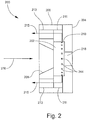
- FIG 2 is a side, partially cut-away view of an example of a target 200 according to the present teachings
- Figure 3 is a perspective view from the back side.
- the target 200 may be utilized in a radionuclide production system such as illustrated by example in Figure 1 , or in other, differently configured radionuclide production systems.
- the target 200 includes a target body 202 that may be mounted in a recess of a front target section 204.
- a target cavity and various coolant passages defining a plurality of coolant paths are formed in the target body 202 as described below.
- the front target section 204 closes off the front side of the target cavity, and includes a target window 218 for receiving a particle beam 114 as described above.
- the front target section 204 abuts a medial target section 206 that surround the target body 202.
- the back side of the target 200 receives an input flow of coolant from a coolant input line 276 in a manner described below.
- an input plenum (or manifold, chamber, conduit, etc.) 208 of any suitable design is interposed between the coolant input line 276 and the back side of the target body 202 for receiving the input coolant.
- the input plenum 208 may be formed by a coolant inlet body or region of the medial target section 206 for distributing coolant to the back side of the target body 202 in a manner described below.
- a plurality of parallel grooves 344 ( Figure 3 ) is formed in the back side of the target body 202.
- the input plenum 208 may taper in the direction of the back side to direct the input coolant flow to the grooves 344.
- the coolant outlet is implemented as a plurality of radial outflow bores 224 circumferentially distributed about the target body 202.
- the radial outflow bores 224 may terminate at a lateral outer wall 210 of the target body 202.
- the radial outflow bores 224 may fluidly communicate with one or more coolant output lines 178 ( Figure 1 ) to enable removal of heat from the target 200 and the target material residing in the target 200, as noted above.
- an output plenum of any suitable design may be provided.
- the output plenum includes one or more chambers 211 and radially distributed axial bores 213 formed in the medial target section 206.
- the input plenum 208 has an entrance 341 that may have any suitable shape and size.
- the input plenum 208 is shaped so as to transition to an elongated slot or slit 342 that serves as the entrance to the grooves 344 formed in the back side of the target body 202.
- Figure 3A illustrates the elongated slot 342 in front of the grooves 344. A portion of these grooves 344 are visible through the elongated slot 342.
- the elongated slot 342 is oriented along a vertical direction in Figure 3A .
- the term “vertical” is relative to the perspective of Figure 3A and that in practice no limitations are placed on the orientation of the target 200 or any of its components relative to any particular frame of reference.
- the grooves 344 are oriented transversely relative to the elongated slot 342.
- the grooves 344 may be characterized as being horizontal although again it will be understood that the term “horizontal” is utilized in a relative sense without any limitation being placed on a particular orientation for the grooves 344.
- the elongated slot 342 is dimensioned such that coolant flowing through the elongated slot 342 will be divided into each of the grooves 344.
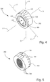
- Figure 4 is a perspective view of the front side of the target 200 (or at least the main target section 202 ) according to the presently described example.
- Figure 4 provides three mutually orthogonal axes that intersect at a point within the target 200 such as in a target cavity 420 thereof: a lateral axis A passing through the target cavity 420 from the front side to the back side, a longitudinal axis B passing through the target cavity 420 from the bottom to the top (from the perspective of Figure 4 ), and a transverse axis C also passing through the target cavity 420.
- the lateral axis A may be associated with a depth of the target 200
- the longitudinal axis B may be associated with a length or height of the target 200
- the transverse axis C may be associated with a width of the target 200.
- the target cavity 420 includes a lateral inner wall 422 that defines the cross-section of the target cavity 420 in the plane of the longitudinal axis B and the transverse axis C .
- the cross-section of the target cavity 420 may include an oblong section that adjoins a rounded top end and a rounded bottom end. That is, the target cavity 420 is elongated in the longitudinal direction.
- the target cavity 420 may open at the front face of the target 200 and may be bounded by the front target section 204 ( Figure 2 ) after assembly.
- a channel 424 surrounding the target cavity may be formed in the front face for receiving a suitable gasket or other sealing component (not shown), thereby forming a fluid seal at the interface between the main target section 202 and the front target section 204.
- Figure 4 also shows the circumferential series of radial outflow bores 224 that open at the outer surface of the main target section 202.
- term "radial" is relative to the intersection point of the three reference axes A, B and C and is not intended to limit the target 200 as having a circular shape or any other particular shape.
- Figure 4 also shows a target inlet (or outlet) bore 432.
- the target inlet bore 432 may open at a flat section to facilitate fluid connection with a fitting or other component.
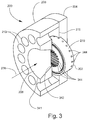
- Figure 5 is a perspective view of the back side of the target 200 (or at least the main target section 202 ) according to the present example.
- the plurality of transversely oriented grooves 344 is formed in the back face.
- the grooves 344 are adjacent to the target cavity 420 ( Figure 4 ).
- the respective widths of the grooves 344 are sized so as to be somewhat greater than the width of the cross-section of the target cavity 420 at all elevations of the target cavity 420. Accordingly, the grooves 344 may collectively exhibit the rounded and oblong shape of the target cavity 420 that characterizes the present example.
- the widths of the grooves 344 enable coolant to be routed in close proximity with the target cavity 420 in the lateral direction to maximize heat transfer from the target cavity 420.
- Figure 6 is an elevation view of the back side of the target 200.
- Each groove 344 is separated from an adjacent groove 344 by a thin, transverse groove wall 646.
- Each groove 344 runs in the transverse direction between a first groove end 652 and an opposing second groove end 654.
- Each groove end 652 and 654 fluidly communicates with at least one peripheral bore 656 and 658.
- Some of the grooves 344 may communicate with more than one peripheral bore 656 and 658.
- the number of grooves 344 may be equal to half the number of peripheral bores 656 and 658 , or less than half the number of peripheral bores 656 and 658.
- the upper two grooves 344 and the bottom two grooves 344 each communicate with two peripheral bores 656 and 658 at their respective ends 652 and 654 for ease of fabrication and to facilitate the close spacing between adjacent peripheral bores 656 or 658.
- the peripheral bores 656 and 658 circumscribe the cross-section of the target cavity 420 ( Figure 4 ) in close proximity therewith and run in the lateral direction toward the front side of the target 200. From Figures 3 and 6 , it can be seen that each individual groove 344 splits the coolant input flow from the elongated slot 342 ( Figure 3 ) into two flows that run in opposite transverse directions to respective peripheral bores 656 and 658 located at the first groove end 652 and second groove end 654.
- each groove 344 may split the coolant input flow generally evenly into the two transverse directions.
- the width and/or the position of the elongated slot 342 may vary along the longitudinal axis B to consequently vary the flow of coolant into various grooves 344 and corresponding peripheral bores 656 and 658.
- the fourteen coolant flow paths entering the grooves 344 are thus divided into twenty-eight transverse coolant flow paths.
- additional flow splitting occurs.
- the present example includes twenty-eight groove ends 652 and 654 but thirty-six peripheral bores 656 and 658.
- some of the twenty-eight flow paths running transversely to the twenty-eight groove ends 652 and 654 are further divided.
- a total of thirty-six coolant flow paths are provided in the corresponding peripheral bores 656 and 658 in the present example.
- the thirty-six coolant flow paths run through the peripheral bores 656 and 658 in the lateral direction in close proximity to each other and to the target cavity 420, thereby enabling a highly efficient means for removing heat from the target material in the target cavity 420.
- the number of coolant flow paths running in the various directions described herein may be different, the presently illustrated implementation being but one example.
- each groove wall 646 (in the longitudinal direction) ranges from 0.002 to 0.125 inch (0.00508 to 0.3175 cm).
- the cross-sectional area of each groove 344 may be defined by the width of the groove 344 in the transverse direction and the height of the groove 344 in the longitudinal direction (between adjacent groove walls 646).
- the height of each groove 344 ranges from 0.01 to 0.125 inch (0.0254 to 0.3175 cm).
- the diameter of each peripheral bore 656 and 658 ranges from 0.01 to 0.25 inch (0.0254 to 0.635 cm).
- the peripheral bores 656 and 658 may generally be divided into a first set associated with the first groove ends 652 and a second set associated with the second groove ends 654. In each first or second set, the peripheral bores 656 and 658 are closely spaced with each other to maximize the amount of "coverage" of the target cavity 420 and thus the amount of surface area of the peripheral bores 656 and 658 available for transferring heat from the target cavity 420.
- the gap or spacing 648 between any pair of adjacent peripheral bores 656 or 658 of the first or second set ranges from 0.002 to 0.125 (0.00508 to 0.3175 cm). The minimal amount of target structure between adjacent peripheral bores 656 or 658 result in the dense coverage of the target cavity discussed above.
- the uppermost peripheral bore 656 of the first set is spaced at a greater distance from the uppermost peripheral bore 658 of the second set (across the longitudinal axis B) in comparison to the spacing 648 between adjacent peripheral bores 656 or 658 of the first or second set. The same may be said for the respective lowermost peripheral bores 656 or 658 of the first and second sets.
- This additional spacing is done in the present implementation merely to accommodate the location of the target material inlet bore and outlet bore, which by example are respectively positioned at the top and bottom of the target cavity 420 as shown in Figures 3-5 and 10 .
- target material inlet bore and outlet bore may be located in other positions whereby additional spacing between any two adjacent peripheral bores 656 or 658 occurs at a different location or not at all.
- the division of the peripheral bores 656 and 658 into first and second sets is conceptual and done for illustrative purposes.
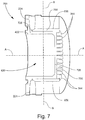
- Figure 7 is a perspective, cross-sectional view of the target that has been cut-away at a plane of the lateral axis A and longitudinal axis B that reveals two of the peripheral bores 656 fluidly interconnecting respective grooves 344 and radial outflow bores 224.
- the target cavity 420 is bounded by the lateral inner wall 422 and an adjoining back inner wall 726.
- the lateral inner wall 422 is adjacent to the circumferentially surrounding peripheral bores 656 and separated from the peripheral bores 656 by a relatively small distance through an annular portion 728 of the target structure.
- the annular portion 728 has a thickness (in any radial direction relative to the lateral axis A) ranging from 0.002 to 0.5 inch (0.00508 to 1.27 cm). In other non-limiting examples, the thickness of the annular portion 728 ranges from 0.005 to 0.15 inch (0.0127 to 0.381 cm).
- the peripheral bores 656 run parallel to the lateral inner wall 422 such that the thickness of the annular portion 728 is uniform along the lateral direction. In alternative implementations, however, the peripheral bores 656 and/or the lateral inner wall 422 may be oriented such that this parallelism is not maintained.
- the series of peripheral bores 656 largely spans the entire extent of the area of the lateral inner wall 422 coaxially about the lateral axis A (see also Figure 6 ). Consequently, the peripheral bores 656 collectively provide a large surface area for transferring heat from the lateral inner surface 422, through the annular portion 728, and to the coolant flowing through the peripheral bores 656.
- Each peripheral bore 656 is bounded by an inner peripheral bore wall 758 that extends from the corresponding groove 344 to the corresponding radial outflow bore 224.
- Each inner peripheral bore wall 758 has a surface area, and the total surface area of the plurality of peripheral bores 656 may be defined as the summation of the surface areas of the individual inner peripheral bore walls 758.
- the back inner wall 726 of the target cavity 420 is adjacent to the grooves 344 and separated from the grooves 344 by a relatively small distance through a back (or longitudinal) portion 730 of the target structure.
- the back portion 730 has a thickness (in the lateral direction, over at least a majority of the grooves 344) ranging from 0.002 to 0.5 (0.00508 to 1.27 cm).
- the series of parallel grooves 344 spans beyond the extent of the area of the back inner wall 726 to facilitate maximizing coverage of the target cavity 420 by the peripheral bores 656, although in other examples may span at least a majority of the area of the back inner wall 726.
- the transverse groove walls or septa 646 ( Figure 6 ) are thin. Consequently, the grooves 344 collectively provide a large surface area for transferring heat from the back inner wall 726 , through the back portion 730, and to the coolant flowing through the grooves 344.
- the total cross-sectional area of the plurality of grooves 344 may be defined as the summation of the cross-sectional areas of the individual grooves 344.
- each groove 344 generally defines two coolant flow paths running along the transverse direction, with one coolant flow path running to the peripheral bore(s) 656 located at one groove end 652 ( Figure 6 ) and the other coolant flow path running the opposing peripheral bore(s) 658 located at the other groove end 654 of the same groove 344.
- Each coolant flow path then takes an orthogonal turn into a corresponding peripheral bore 656 or 658 and runs in the lateral direction, again in close proximity to the target cavity 420.
- the coolant continues to remove heat from the target cavity 420 as it flows toward the front side of the target 200 along the lateral flow paths.
- the peripheral bores 656 and 658 may extend over a large majority of the depth of the target cavity 420.
- Each peripheral bore 656 and 658 runs to at least one radial outflow bore 224 .
- the radial outflow bores 224 may be sized (e.g., cross-sectional flow area) larger than the peripheral bores 656 and 658 and positioned such that more than one peripheral bore 656 and 658 terminates at the same radial outflow bore 224.
- the number of radial outflow bores 224 may be equal to or less than the number of peripheral bores 656 and 658. This configuration also minimizes the pressure drop in the radial outflow bores 224.
- the cross-sectional flow area of each radial outflow bore 224 may progressively increase along the radial direction from the end of the peripheral bore 656 or 658 to the outer lateral wall 210 of the target structure, as illustrated in Figure 7 .
- the coolant then takes an orthogonal turn into the radial outflow bore 224 .
- the coolant then runs in a radial outward direction to the end of the radial outflow bore 244 at the lateral outer surface 210 of the target 200 . While flowing in the radial outflow bore 244, the coolant continues to pick up heat energy.
- the radial outflow bores 244 are located in close proximity to the front side of the target 200 that receives the particle beam 214. In some non-limiting examples, the radial outflow bores 244 are located at a distance from the front side along the lateral axis A ranging from 0.01 to 0.5 inch (0.0254 to 1.27 cm).
- the radial outflow bores 244 are dimensioned so as to provide a large surface area available for heat transfer from the structural (solid) body constituting the target 200 .
- the coolant flowing through the radial outflow bores 244 is able to remove heat from the structural target body as well as from the target material being irradiated in the target cavity 420.
- the coolant may then be flowed away from the target 200 and recirculated back to the grooves 344 in the manner described above.
- both the grooves 344 on the back side of the target 200 and the peripheral bores 656 and 658 running through the depth of the target 200 cover the inside surfaces of the target cavity 420 very densely and with a minimum of wall thickness between the coolant and the target cavity 420.
- the radial outflow bores 224 provide additional heat-removing capacity in the manner described above.
- the transverse grooves 344, peripheral bores 656 and 658 and radial outflow bores 224 are dimensioned and positioned in a configuration that maintains a high-velocity coolant flow through the target 200 from input to output, thereby enabling the coolant to rapidly carry away the heat being deposited by the particle beam 214. This foregoing configuration therefore maximizes heat removal from the target cavity 420.
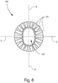
- Figure 8 is a cross-sectional elevation view of the target 200 that has been cut-away at a plane of the longitudinal axis B and transverse axis C that reveals the radial outflow bores 224 .
- the center of the target 200 is taken to be the geometrical center of the target cavity 420 , and the origin of the intersecting lateral axis A , longitudinal axis B and transverse axis C has been located at this center.
- each radial outflow bore 224 is located along a radius projected from the center.
- one or more of the radial outflow bores 224 may fluidly communicate with more than one peripheral bore 656 or 648 ( Figure 7 ).
- each radial outflow bore 224 communicates with two peripheral bores 656 or 658.
- the thirty-six lateral coolant flow paths running through the respective peripheral bores 656 and 658 are reduced to eighteen radial coolant flow paths in the eighteen radial outflow bores 224 illustrated in Figure 8 .
- Figure 9 is a cross-sectional elevation view of the target 200 that has been cut-away at a plane of the lateral axis A and transverse axis C that reveals one of the grooves 344 in fluid communication with a corresponding pair of peripheral bores 656 and 658 and radial outflow bores 224.
- the coolant input flow 902 encounters the grooves 344 in close proximity with back inner wall 726 of the target cavity 420 , and thus the coolant is able to immediately begin removing heat from the target cavity 420.
- the input flow 902 encounters the grooves 344
- the input flow 902 is initially divided along the longitudinal direction into each groove 344 .
- each groove 344 is associated with a coolant input flow path 902 separate from the other grooves 344 .
- the grooves 344 are orthogonal to the initial input flow 902.
- each groove 344 the input flow 902 is further divided such that one part of the input flow 902 is diverted to one groove end 652 while the other part of the input flow 902 is diverted to the opposing groove end 654 of the same groove 344 .
- the resulting two transverse coolant flow paths in the groove 344 are indicated by arrows 904 and 906.
- that transverse coolant flow 904 and 906 is then diverted orthogonally into the peripheral bore 656 or 658 located at that groove end 652 or 654 (or one of the peripheral bores 656 or 658 in the case where more than one peripheral bore 656 or 658 is formed at a single groove end 652 or 654 ).
- the resulting lateral coolant flow paths are indicated by arrows 912 and 914 .
- the lateral coolant flows 912 and 914 then run through the respective peripheral bores 656 and 658 to the corresponding radial outflow bores 224.
- the coolant in each radial outflow bore 224 reaches the outer lateral wall 210 of the target 200 and is conducted away to an external heat exchanging device as described previously in this disclosure.
- Figure 9 may be considered as showing the top end of the target cavity 420 at which the target material inlet bore 432 is located by example (or where the outlet bore may be located in another example).
- Figure 9 may be considered as showing the bottom end of the target cavity 420 at which the target material outlet bore (or inlet bore 432 ) is located.
- the following description will refer to the target material inlet bore 432 , as located at the top end in the present example, with the understanding that the discussion may also apply to the target material outlet bore and/or to the bottom end of the target cavity 420.
- the inlet bore 432 is surrounded by an inlet pocket or depression 982 formed in the lateral inner wall 422 of the target cavity 420.
- the inlet pocket 982 may have any size and shape suitable for complete filling of the target cavity 420.
- the length of the inlet pocket 982 in the lateral direction may be elongated relative to the width of the inlet pocket 982 in the transverse direction.
- the inlet pocket 982 is elongated in the lateral direction and the width of the inlet pocket 982 in the transverse direction gradually tapers down (decreases) in the lateral direction toward the front side of the target 200.
- the target material inlet bore 432 is located in the region of the inlet pocket 982 having the maximum width.
- an outlet pocket (not shown) may surround the outlet bore, and may have any size and shape suitable for complete recovery of target material.
- the outlet pocket may be sized and shaped similarly to the illustrated inlet pocket 982.
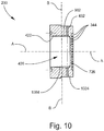
- Figure 10 is a cross-sectional elevation view of the target 200 that has been cut-away at a plane of the lateral axis A and longitudinal axis B that reveals the target material inlet bore 432 and an outlet bore 1034 .
- the inlet bore 432 fluidly communicates with an inlet pocket 982 as described above
- the outlet bore 1034 fluidly communicates with an outlet pocket 1084 .
- the respective sizes and shapes of the inlet pocket 982 and the outlet pocket 1084 may be the same or different.
- the above-noted tapering of each pocket 982 and 1084 also occurs along the longitudinal axis A , with each pocket 982 and 1084 being deepest in the vicinity of the inlet bore 432 or outlet bore 1034.
- Figure 11 is a perspective view of an example of a target assembly 1100 in which the target 200 may be included
- Figure 12 is a cross-sectional view of the target assembly 110 .
- the target assembly 1100 may be utilized in a radionuclide production system such as illustrated by example in Figure 1 , or in other, differently configured radionuclide production systems.
- the target assembly 1100 generally includes the front target section 204 and the medial target section 206 as described above.
- the target assembly 1100 in this example includes a back target section 1121 .
- the back target section 1121 may include a chamber 1223 ( Figure 12 ) that serves as part of the output plenum for carrying away heated output coolant from the target body 202 .
- the back target section 1121 may also include bores communicating with respective coolant input fittings 1125 and coolant output fittings 1127 .
- the coolant input fittings 1125 communicate with the input plenum 208 and the coolant output fittings 1127 communicate with the chamber 1223 of the output plenum.
- the target assembly 1100 may also include a beam guide 1130 for directing a particle beam from a particle beam source (e.g., the particle beam source 140 shown in Figure 1 ) to the target window 218 ( Figure 12 ).
- a particle beam source e.g., the particle beam source 140 shown in Figure 1
- various adjacent components of the target assembly 1100 may be fluidly sealed by sealing elements (e.g., o-rings, gaskets, etc.) seated in grooves or channels formed in or on such components.
- sealing elements e.g., o-rings, gaskets, etc.
- the arrangement of the target window 218 interposed between the target body 202 and the front target section 204 may be fluidly sealed by a sealing element seated in a channel 1241 formed in the front side of the target body 202 , and/or by a sealing element seated in a channel 1243 formed in the front target section 204.
- the target window 218 may have any shape and planar size, so long as the outer diameter (or other relevant dimension, more generally perimeter) of the target window 218 is large enough that the target window 218 covers the opening of the target cavity 420 .
- the outer perimeter of the target window 218 is large enough to accommodate the use of fluid sealing means such as the illustrated sealing element/channel 1241 and/or 1243 .
- Figure 12 illustrates one non-limiting example in which the area of the target window 218 is coextensive with that of the front side of the target body 202.
- the location of the peripheral bores 656 in relation to the target cavity 420 , as well as to other components of the target 200 and associated target assembly 1100 optimizes the ability of the coolant circulating through the target 200 to remove heat from the target 200.
- the peripheral bores 656 closely surround the target cavity 420 and span most of the axial depth of the target cavity 420 to maximize the amount of heat transfer therefrom.
- the peripheral bores 656 are arranged about a perimeter at a radial distance not much greater than the radial extent of the target cavity 420.
- This arrangement of the peripheral bores 656 may be characterized in relation to the target window 218 and the associated sealing element/channel 1241 and/or 1243. It can be seen that the perimeter of the peripheral bores 656 is less that the outer perimeter of the target window 218. Stated in another way, the area taken up by the arrangement of peripheral bores 656 is within the area of the target window 218. Additionally or alternatively, the perimeter of the peripheral bores 656 is less that the perimeter of the sealing element/channels 1241 and 1243.
- This arrangement of the peripheral bores 656 is facilitated by the provision of the radial outflow bores 244, which allow the peripheral bores 656 to run close to the target cavity 420 and close up to the target window 218. Additionally, the radial outflow bores 244 maximize heat removal from the target window 218 and the region of the target body 202 proximal to the target window 218.
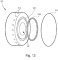
- Figure 13 is an exploded perspective view of the target 200, a sealing element 1351 , and the target window 218.
- the peripheral bores 656 ( Figure 12 ) may be placed within the perimeter of the channel 1241 in which the sealing element 1351 is seated, as well as within the perimeter of the target window 218. Coolant from the peripheral bores 656 is carried away by the radial outflow bores 244, enabling the peripheral bores 656 to be immediately adjacent to the target cavity 240.
- Figure 13 also shows an alternative circular cross-section for the target cavity 240.
- Figure 14 is an exploded perspective view of a conventional design of a target 1400 and its associated sealing element 1451 and target window 1418.
- the sealing element 1451 is seated in a recess 1441 formed in the target body and the target window 1418 is mounted in another recess 1445 concentrically surrounding the sealing element recess 1441.
- This conventional target 1440 has a radial distribution of axial bores 1456 for conducting coolant from the back side to the front side of the target 1400.
- These axial bores 1456 must be arranged far away from the target cavity 1440 to avoid the target window 1418 and the sealing element 1451.
- the axial bores 1456 are located outside the perimeter of both the sealing element recess 1441 and the target window 1418.
Landscapes
- Physics & Mathematics (AREA)
- Chemical & Material Sciences (AREA)
- Chemical Kinetics & Catalysis (AREA)
- High Energy & Nuclear Physics (AREA)
- Optics & Photonics (AREA)
- Engineering & Computer Science (AREA)
- Plasma & Fusion (AREA)
- Spectroscopy & Molecular Physics (AREA)
- Particle Accelerators (AREA)
Description
- The present invention relates generally to particle beam targets utilized for producing radionuclides. More particularly, the present invention relates to the cooling of targets during irradiation by a particle beam.
- Radionuclides may be produced by bombarding a target with an accelerated particle beam as may be generated by a cyclotron, linear accelerator, or the like. The target contains a small amount of target material that is typically provided in the liquid phase but could also be a solid or gas. The target material includes a precursor component that is synthesized to the desired radionuclide in reaction to irradiation by the particle beam. As but one example, F-18 ions may be produced by bombarding a target containing water enriched with the 0-18 isotope with a proton beam. After bombardment, the as-synthesized F-18 ions may be recovered from the water after removing the water from the target. The production of F-18 ions in particular has important radiopharmaceutical applications. For instance, the as-produced F-18 ions may be utilized to produce the radioactive sugar fluorodeoxyglucose (2-fluoro-2-deoxy-D-glucose, or FDG), which is utilized in positron emission tomography (PET) scanning. PET is utilized in nuclear medicine as a metabolic imaging modality in the diagnosis of cancer.
- The production of radionuclides such as F-18 ions is an expensive process, and thus any improvement to the production efficiency and yield would be desirable. Unfortunately, the application of the particle beam initiates the desired nuclear reaction in only a very small fraction of the radionuclide precursors in the target. The particle beam deposits a significant amount of heat into the target material residing in the target during bombardment. For instance, in the conventional production of F-18 ions, it has been found that only about one of every 2,000 protons stopping in the target water actually produces the desired nuclear reaction, with the rest of the proton beam merely depositing heat. Yet the amount of radioactive product that can be produced in a radionuclide target is proportional to the amount of heat that can be removed during bombardment of the target material of choice. Moreover, the rapidly increasing vapor pressure developed in the target chamber containing the target material as a result of the heat deposition may cause the target to structurally fail if the heat deposition is not adequately removed.
- Radionuclide production yield could be increased by increasing the beam energy inputted to the target, but due to the foregoing problems the beam energy has been intentionally limited in conventional systems. Conventional radionuclide production systems may provide a means for cooling the beam targets generally by routing a heat transfer medium such as water to the target to carry heat away therefrom during bombardment. Conventional target designs, however, do not have sufficient capacity for heat removal, and as a result the radionuclide production yield and efficiency has been less than desirable in conventional targets.
- In view of the foregoing, there is an ongoing need for beam targets utilized for radionuclide production that enable increased capacity and efficiency for removing heat and thus improved radionuclide production yield and efficiency. The heat energy deposited in the target material may cause boiling and generate bubbles or voids in the volume of target material. Bubbles or voids do not yield radionuclides; the particle beam simply passes through the bubbles or voids to the back of the target structure.
-
WO 2008/073468 A1 relates to a system and method provided for reclaiming an enriched radioisotope starting material from a target body. A chemical protective layer is disposed between a radioisotope starting material and a base material of the target body. After the target body is irradiated, the irradiated radioisotope starting material can be removed without removing the base material due to the protection provided by the chemical protective layer. The target body has the protective layers and has at its backside a hollow chamber being a coolant passage which in turn has tubular openings to the backside thereof. The tubular openings extend at the backside from the target body through the hollow chamber. The tubular openings may be connected internally within the base layer such that a channel is formed between the two tubular openings. Using external tubes coupled to the openings, coolant may enter through opening into the coolant passage disposed therebetween and exit the hollow chamber via opening back to the coolant source. Grooves disposed on the backside of the target body are configured to increase the surface area of the target body, thereby improving heat transfer from the target to the coolant. - The present invention defines a particle beam target according to
claim 1 as well as a method for cooling a particle beam target according to claim 13. Particular embodiments of the present invention are defined in the dependent claims. - Other devices, apparatus, systems, methods, features and advantages of the disclosure will be or will become apparent to one with skill in the art upon examination of the following figures and detailed description.
- The invention can be better understood by referring to the following figures. The components in the figures are not necessarily to scale, emphasis instead being placed upon illustrating the principles of the invention. In the figures, like reference numerals designate corresponding parts throughout the different views.
-
Figure 1 is a simplified schematic view of an example of a radionuclide production apparatus or system as an example of an operating environment in which a target according to the present teachings may be implemented. -
Figure 2 is a side, partially cut-away view of an example of a target according to the present teachings. -
Figure 3 is a perspective view of the back side of the target illustrated inFigure 2 . -
Figure 3A is an elevation view of an entrance slot in front of the back side of the target. -
Figure 4 is a perspective view of the front side of the target. -
Figure 5 is another perspective view of the back side of the target. -
Figure 6 is an elevation view of the front side of the target. -
Figure 7 is a perspective, cross-sectional view of the target that has been cut-away at a plane that reveals peripheral bores fluidly interconnecting respective grooves and radial outflow bores. -
Figure 8 is a cross-sectional elevation view of the target that has been cut-away at a plane that reveals the radial outflow bores. -
Figure 9 is a cross-sectional elevation view of the target that has been cut-away at a plane that reveals one of the grooves in fluid communication with a corresponding pair of peripheral bores and radial outflow bores. -
Figure 10 is a cross-sectional elevation view of the target that has been cut-away at a plane that reveals a target material inlet bore and outlet bore. -
Figure 11 is a perspective view of an example of a target assembly in which the target may be included. -
Figure 12 is a cross-sectional view of the target assembly illustrated inFigure 11 . -
Figure 13 is an exploded perspective view of the target and an associated sealing element and target window. -
Figure 14 is an exploded perspective view of a conventional design of a target and associated sealing element and target window. - By way of example,
Figures 1-13 illustrate various implementations of a target and associated radionuclide production apparatus or system. The various implementations provide a highly efficient solution for cooling a target cavity containing target material bombarded by particles (e.g., protons) for the purpose of obtaining a maximum amount of heat removal from the target material and thereby maximizing the amount of radioactive product that can be produced from that target material. As noted above, the amount of radioactive product that can be produced in a radionuclide target is proportional to the amount of heat that can be removed during bombardment of the target material of choice. In various implementations, a high rate of heat removal is accomplished at least in part by providing numerous individual, high-velocity, multi-stage coolant flow paths arranged in parallel and closely spaced to each other ad in close proximity to the target cavity containing the target material to be cooled. This configuration maximizes the heat flow from the target medium to the coolant by minimizing the heat conduction distance (i.e., the thickness of the target structure across which the heat must be transferred). The target may be implemented in connection with any type of liquid coolant and any type of radionuclide synthesis process. A target consistent with the present teaching has experimentally demonstrated superior performance in transferring heat away from target material, as compared to conventional targets. -
Figure 1 is a simplified schematic view of an example of a radionuclide production apparatus orsystem 100 as an example of an operating environment in which atarget 102 according to the present teachings may be implemented. Thetarget 102 generally includes a front side (beam input side) 112 at which aparticle beam 114 is directed and a back side (coolant input side) 116 which, in the presently described implementation, receives an input of any suitable liquid coolant (e.g., water). Thetarget 102 also generally includes a target body that may include one or more parts assembled together. Insofar as thetarget 102 may include assembled components, thetarget 102 may also be referred to herein as a target assembly. Thetarget 102 is typically constructed from a suitable metal or metal alloy, a few examples being silver, aluminum, gold, nickel, titanium, copper, platinum, tantalum, niobium, and stainless steel. At thefront side 112, thetarget 102 includes atarget window 118 of any material suitable for transmitting theparticle beam 114 therethrough while minimizing loss of beam energy. Typically, thetarget window 118 is constructed from a metal or metal alloy, a few examples being the commercially available HAVAR® alloy, titanium, tantalum, tungsten, and gold. The thickness of thetarget window 118 may range, for example, from 0.3 to 30 µm. A target chamber orcavity 120 is formed within the target body and defines an interior of the target body into which theparticle beam 114 is directed via thetarget window 118. In practice, thetarget cavity 120 contains a flowable target material that includes a radionuclide precursor, the composition of which will depend on the type of radionuclide being synthesized. As a non-limiting example, the internal volume (or size) of thetarget cavity 120 may range from 1.0 to 10 cm3. Acoolant inlet 122 and acoolant outlet 124 are also formed in the target body. Thecoolant inlet 122 and thecoolant outlet 124 communicate with each other via a coolant flow system internal to the target body, as described in more detail below. - In some non-limiting examples, particularly where the target material is a liquid, the volume of the
target cavity 120 after assembly of thetarget window 118 thereto ranges from 0.5 cc (or ml) to 20 cc. In other non-limiting examples, particularly where the target material is a solid, the volume of thetarget cavity 120 after assembly of thetarget window 118 thereto ranges from 0.1 cc to 20 cc. In other non-limiting examples, particularly where the target material is a gas, the volume of thetarget cavity 120 after assembly of thetarget window 118 thereto ranges from 100 cc to 10,000 cc (10 L). - One or more target material transfer bores may be formed in the
target 102 for inputting target material into and/or outputting target material from thetarget cavity 120. In the present example, a target material inlet bore 132 and a separate target material outlet bore 134 are formed in the target body and fluidly communicate with thetarget cavity 120. The locations of the inlet bore 132 and the outlet bore 134 are arbitrary in the schematic view of theFigure 1 , and may depend on whether it is desired to load thetarget 102 with target material from the top or the bottom. For example, the inlet bore 132 may alternatively be located at the top of thetarget cavity 120 and the outlet bore 134 may be located at the bottom of thetarget cavity 120. As a further alternative, thetarget 102 may include asingle bore target cavity 120 and removing target material (including radionuclides) from thetarget cavity 120. - The illustrated example, in which a single fluid transfer bore 132 or 134 or both an
inlet bore 132 and an outlet bore 134 are utilized, is directed primarily to the use of a liquid target material. It will be appreciated by persons skilled in the art that in other cases, such as where the target material is a solid or a gas, the inlet bore 132 and/or outlet bore 134 may be modified as necessary or not utilized at all. As one example of the use of a solid target material, molten target material could first be loaded into thetarget cavity 120 and allowed to solidify, and the target material is maintained in the solid phase during application of the particle beam due to the cooling provided by the present teachings. - The
radionuclide production apparatus 100 includes aparticle beam source 140 such as, for example, a cyclotron, a linear accelerator, or the like. The structure and operation of theparticle beam source 140 may depend on the type ofparticle beam 114 utilized. As an example, theparticle beam 114 may be a proton beam. The proton beam is typically applied at a beam power of about 0.5 kW or greater, up to a practical limit that avoids structural failure of thetarget 102 and impairment of the desired nuclear reaction. In conventional targets, the beam power typically does not exceed about 2 kW. In at least some implementations of thetarget 102 taught herein, it is expected that the beam power may be increased to about 10 kW or greater. - The
radionuclide production apparatus 100 also includes a target material transport circuit orsystem 150. The targetmaterial transport system 150 may include any suitable target material source (supply, reservoir, etc.) 152, a device for moving the target material such as, for example, apump 154, and a targetmaterial input line 156 for conducting the target material from thetarget material source 152 to the inlet bore 132 and thus thetarget cavity 120. The targetmaterial transport system 150 may be implemented as a loop, in which case the above-noted outlet bore 134 is included as well as a targetmaterial output line 158 that leads back to thetarget material source 152 or at least back to thepump 154. By utilizing the loop configuration, the target material may be flowed through the inlet bore 132, filling thetarget cavity 120, and through the outlet bore 134 prior to activation of theparticle beam 114. In this manner, the targetmaterial transport system 150 may be utilized to purge thetarget cavity 120 of bubbles, gases, contaminants, or any other undesired components prior to application of theparticle beam 114 and ensuing synthesis. In practice, thetarget cavity 120 may be filled from the top (in which case the inlet bore 132 may be located at the top, as in the illustrated example) or from the bottom (in which case the inlet bore 132 may be located at the bottom). The schematically illustrated positions of thetarget material source 152 and thepump 154 may be switched as needed for top-filling or bottom-filling. - In the present example, the target
material transport system 150 may also be utilized to route as-produced radionuclides to a desiredradionuclide destination 162 for further processing, such as a hot lab. For this purpose, aradionuclide output line 164 is schematically shown as fluidly communicating with the target material outlet line 158 (or, alternatively, with the target material inlet line 156). A valve or other controllable flow-diverting means (not shown) may serve as an interface between the targetmaterial transport system 150 and theradionuclide output line 164 for this purpose. - The
radionuclide production apparatus 100 also includes a coolant circulation circuit orsystem 170. Thecoolant circulation system 170 may include any suitable coolant conditioning apparatus (heat exchanger, condenser, evaporator, and the like) 172 for providing coolant to thetarget 102, receiving heated coolant from thetarget 102, removing heat from the heated coolant, and repeating the cycle as needed during synthesis. Thecoolant circulation system 170 may also include a device for moving the coolant to and from thetarget 102 such as, for example, apump 174, acoolant input line 176 for conducting the coolant from thecoolant conditioning apparatus 172 to thecoolant inlet 122 of thetarget 102, and acoolant output line 178 for conducting the heated coolant from thecoolant outlet 124 oftarget 102 back to thecoolant conditioning apparatus 172. - In practice, the
target material source 152 is provided with a suitable supply of target material, and thetarget cavity 120 is loaded with a suitable amount of target material by flowing the target material from thetarget material source 152 into thetarget cavity 120. Once thetarget cavity 120 is filled (partially or entirely, depending on design) with a desired amount of target material, theparticle beam source 140 is operated to generate aparticle beam 114, which is directed into thetarget cavity 120 via thetarget window 118 for interaction with the target material. Application of theparticle beam 114 results in synthesis of radionuclides from the target material in thetarget cavity 120. After a sufficient amount of time during the "beam-on" stage has elapsed, theparticle beam 114 is switched off and the as-produced radionuclides are transported to the hot lab orother destination 162 for further processing. - As noted above, during application of the
particle beam 114, a large amount of energy is deposited as heat in the target material residing in thetarget cavity 120. This heat generates a large amount of vapor within thetarget cavity 120 resulting in voids or bubbles within the target material. The voids or bubbles interfere with the particle beam's ability to cause the nuclear reaction needed for radionuclide synthesis, and the vapor pressure may quickly cause thetarget 102 to fail structurally. Hence, the heat must be rapidly removed from thetarget 102 and from the target material residing in thetarget 102. This is accomplished through the operation of thecoolant circulation system 170 during application of theparticle beam 114 in conjunction with a coolant circulation system incorporated into thetarget 102, as described by way of examples below. - A non-limiting example of radionuclide synthesis is the production of the F-18 (18F-) ion (fluorine-18) from the 0-18 (oxygen-18) precursor. In this case, the target material may be provided as 0-18 enriched water, i.e., water in which a desired fraction has the composition H2 18O, and the particle beam is a proton beam. The nuclear reaction is specified as 18O(p,n)18F. Other examples of radionuclides that may be produced include, but are not limited to, N-13, 0-15, and C-11. N-13 is produced from natural water as the target material utilizing alpha-particles according to the nuclear reaction 16O(p,α)13N.
- The
target 102 disclosed herein is particularly suited for use as a "batch" or "static" target. In a batch or static target, the target material is loaded in thetarget cavity 120, the same amount of target material remains in thetarget cavity 120 during synthesis, and the target material (now including radionuclides) is thereafter removed from thetarget 102. An alternative type of target is a recirculating target, in which the target material is circulated through thetarget cavity 120 during application of the particle beam. In a recirculating target, the target material itself may be utilized as a heat transfer medium to some degree because the target material carries heat away from the target and, prior to being recirculated back to the target, may be cooled by a heat exchange system located remotely from and external to the target body. The present teachings, however, encompass the use of thetarget 102 disclosed herein as a recirculating target as an option for increasing the heat-removal capacity of the recirculating target. -
Figure 2 is a side, partially cut-away view of an example of atarget 200 according to the present teachings, andFigure 3 is a perspective view from the back side. Thetarget 200 may be utilized in a radionuclide production system such as illustrated by example inFigure 1 , or in other, differently configured radionuclide production systems. Thetarget 200 includes atarget body 202 that may be mounted in a recess of afront target section 204. A target cavity and various coolant passages defining a plurality of coolant paths (not shown) are formed in thetarget body 202 as described below. Thefront target section 204 closes off the front side of the target cavity, and includes atarget window 218 for receiving aparticle beam 114 as described above. Thefront target section 204 abuts amedial target section 206 that surround thetarget body 202. The back side of thetarget 200 receives an input flow of coolant from acoolant input line 276 in a manner described below. In some implementations, an input plenum (or manifold, chamber, conduit, etc.) 208 of any suitable design is interposed between thecoolant input line 276 and the back side of thetarget body 202 for receiving the input coolant. Theinput plenum 208 may be formed by a coolant inlet body or region of themedial target section 206 for distributing coolant to the back side of thetarget body 202 in a manner described below. In this example, a plurality of parallel grooves 344 (Figure 3 ) is formed in the back side of thetarget body 202. Theinput plenum 208 may taper in the direction of the back side to direct the input coolant flow to thegrooves 344. In the present example, the coolant outlet is implemented as a plurality of radial outflow bores 224 circumferentially distributed about thetarget body 202. The radial outflow bores 224 may terminate at a lateralouter wall 210 of thetarget body 202. The radial outflow bores 224 may fluidly communicate with one or more coolant output lines 178 (Figure 1 ) to enable removal of heat from thetarget 200 and the target material residing in thetarget 200, as noted above. To facilitate routing the coolant from the radial outflow bores 224 to the coolant output line(s) 178, an output plenum of any suitable design may be provided. For this purpose, in the illustrated example the output plenum includes one ormore chambers 211 and radially distributedaxial bores 213 formed in themedial target section 206. - Referring to
Figure 3 , theinput plenum 208 has anentrance 341 that may have any suitable shape and size. In this example, theinput plenum 208 is shaped so as to transition to an elongated slot or slit 342 that serves as the entrance to thegrooves 344 formed in the back side of thetarget body 202.Figure 3A illustrates theelongated slot 342 in front of thegrooves 344. A portion of thesegrooves 344 are visible through theelongated slot 342. Theelongated slot 342 is oriented along a vertical direction inFigure 3A . It will be understood, however, that the term "vertical" is relative to the perspective ofFigure 3A and that in practice no limitations are placed on the orientation of thetarget 200 or any of its components relative to any particular frame of reference. In the present example, thegrooves 344 are oriented transversely relative to theelongated slot 342. Thus, in the example specifically illustrated inFigure 3A , thegrooves 344 may be characterized as being horizontal although again it will be understood that the term "horizontal" is utilized in a relative sense without any limitation being placed on a particular orientation for thegrooves 344. Theelongated slot 342 is dimensioned such that coolant flowing through theelongated slot 342 will be divided into each of thegrooves 344. That is, allgrooves 344 are exposed through theelongated slot 342 as shown inFigures 3 and3A . Thus, for example, if fourteengrooves 344 are provided, the input flow of coolant passing through theelongated slot 342 will be divided into fourteen separate, individual input flow paths, with each input flow path being associated with arespective groove 344. -
Figure 4 is a perspective view of the front side of the target 200 (or at least the main target section 202) according to the presently described example. For reference purposes,Figure 4 provides three mutually orthogonal axes that intersect at a point within thetarget 200 such as in atarget cavity 420 thereof: a lateral axis A passing through thetarget cavity 420 from the front side to the back side, a longitudinal axis B passing through thetarget cavity 420 from the bottom to the top (from the perspective ofFigure 4 ), and a transverse axis C also passing through thetarget cavity 420. Also for reference purposes, the lateral axis A may be associated with a depth of thetarget 200, the longitudinal axis B may be associated with a length or height of thetarget 200, and the transverse axis C may be associated with a width of thetarget 200. This system of three reference axes A, B and C will be utilized in conjunction withFigures 5-10 as well. - As illustrated in
Figure 4 , thetarget cavity 420 includes a lateralinner wall 422 that defines the cross-section of thetarget cavity 420 in the plane of the longitudinal axis B and the transverse axis C. The cross-section of thetarget cavity 420 may include an oblong section that adjoins a rounded top end and a rounded bottom end. That is, thetarget cavity 420 is elongated in the longitudinal direction. In the present example, thetarget cavity 420 may open at the front face of thetarget 200 and may be bounded by the front target section 204 (Figure 2 ) after assembly. Achannel 424 surrounding the target cavity may be formed in the front face for receiving a suitable gasket or other sealing component (not shown), thereby forming a fluid seal at the interface between themain target section 202 and thefront target section 204.Figure 4 also shows the circumferential series of radial outflow bores 224 that open at the outer surface of themain target section 202. In the present context, term "radial" is relative to the intersection point of the three reference axes A, B and C and is not intended to limit thetarget 200 as having a circular shape or any other particular shape.Figure 4 also shows a target inlet (or outlet) bore 432. The target inlet bore 432 may open at a flat section to facilitate fluid connection with a fitting or other component. -
Figure 5 is a perspective view of the back side of the target 200 (or at least the main target section 202) according to the present example. The plurality of transversely orientedgrooves 344 is formed in the back face. Thegrooves 344 are adjacent to the target cavity 420 (Figure 4 ). The respective widths of thegrooves 344 are sized so as to be somewhat greater than the width of the cross-section of thetarget cavity 420 at all elevations of thetarget cavity 420. Accordingly, thegrooves 344 may collectively exhibit the rounded and oblong shape of thetarget cavity 420 that characterizes the present example. As described in more detail below, the widths of thegrooves 344 enable coolant to be routed in close proximity with thetarget cavity 420 in the lateral direction to maximize heat transfer from thetarget cavity 420. -
Figure 6 is an elevation view of the back side of thetarget 200. Eachgroove 344 is separated from anadjacent groove 344 by a thin,transverse groove wall 646. Eachgroove 344 runs in the transverse direction between afirst groove end 652 and an opposingsecond groove end 654. Eachgroove end peripheral bore grooves 344 may communicate with more than oneperipheral bore grooves 344 may be equal to half the number ofperipheral bores peripheral bores grooves 344 and the bottom twogrooves 344 each communicate with twoperipheral bores respective ends peripheral bores peripheral bores Figure 4 ) in close proximity therewith and run in the lateral direction toward the front side of thetarget 200. FromFigures 3 and6 , it can be seen that eachindividual groove 344 splits the coolant input flow from the elongated slot 342 (Figure 3 ) into two flows that run in opposite transverse directions to respectiveperipheral bores first groove end 652 andsecond groove end 654. Assuming the width of theelongated slot 342 is uniform as illustrated inFigure 3 and theelongated slot 342 is positioned centrally between the first groove ends 652 and the second groove ends 654, eachgroove 344 may split the coolant input flow generally evenly into the two transverse directions. In alternative implementations, the width and/or the position of theelongated slot 342 may vary along the longitudinal axis B to consequently vary the flow of coolant intovarious grooves 344 and correspondingperipheral bores - In the illustrated example in which fourteen
grooves 344 are provided, the fourteen coolant flow paths entering thegrooves 344 are thus divided into twenty-eight transverse coolant flow paths. In the illustrated example in which some of the groove ends 652 and 654 include more than oneperipheral bore peripheral bores peripheral bores peripheral bores target cavity 420, thereby enabling a highly efficient means for removing heat from the target material in thetarget cavity 420. In other implementations, the number of coolant flow paths running in the various directions described herein may be different, the presently illustrated implementation being but one example. - In some examples, the thickness of each groove wall 646 (in the longitudinal direction) ranges from 0.002 to 0.125 inch (0.00508 to 0.3175 cm). The cross-sectional area of each
groove 344 may be defined by the width of thegroove 344 in the transverse direction and the height of thegroove 344 in the longitudinal direction (between adjacent groove walls 646). In some examples, the height of eachgroove 344 ranges from 0.01 to 0.125 inch (0.0254 to 0.3175 cm). In some examples, the diameter of eachperipheral bore - In the example illustrated in the
Figure 6 , theperipheral bores peripheral bores target cavity 420 and thus the amount of surface area of theperipheral bores target cavity 420. In some examples, the gap or spacing 648 between any pair of adjacentperipheral bores peripheral bores - It will be noted that in
Figure 6 the uppermostperipheral bore 656 of the first set is spaced at a greater distance from the uppermostperipheral bore 658 of the second set (across the longitudinal axis B) in comparison to thespacing 648 between adjacentperipheral bores peripheral bores target cavity 420 as shown inFigures 3-5 and10 . It will be understood, however, that in other implementations the target material inlet bore and outlet bore may be located in other positions whereby additional spacing between any two adjacentperipheral bores peripheral bores -
Figure 7 is a perspective, cross-sectional view of the target that has been cut-away at a plane of the lateral axis A and longitudinal axis B that reveals two of theperipheral bores 656 fluidly interconnectingrespective grooves 344 and radial outflow bores 224. Thetarget cavity 420 is bounded by the lateralinner wall 422 and an adjoining backinner wall 726. The lateralinner wall 422 is adjacent to the circumferentially surroundingperipheral bores 656 and separated from theperipheral bores 656 by a relatively small distance through anannular portion 728 of the target structure. In some examples, theannular portion 728 has a thickness (in any radial direction relative to the lateral axis A) ranging from 0.002 to 0.5 inch (0.00508 to 1.27 cm). In other non-limiting examples, the thickness of theannular portion 728 ranges from 0.005 to 0.15 inch (0.0127 to 0.381 cm). In the illustrated example, theperipheral bores 656 run parallel to the lateralinner wall 422 such that the thickness of theannular portion 728 is uniform along the lateral direction. In alternative implementations, however, theperipheral bores 656 and/or the lateralinner wall 422 may be oriented such that this parallelism is not maintained. In the illustrated example, the series ofperipheral bores 656 largely spans the entire extent of the area of the lateralinner wall 422 coaxially about the lateral axis A (see alsoFigure 6 ). Consequently, theperipheral bores 656 collectively provide a large surface area for transferring heat from the lateralinner surface 422, through theannular portion 728, and to the coolant flowing through the peripheral bores 656. Eachperipheral bore 656 is bounded by an innerperipheral bore wall 758 that extends from the correspondinggroove 344 to the corresponding radial outflow bore 224. Each innerperipheral bore wall 758 has a surface area, and the total surface area of the plurality ofperipheral bores 656 may be defined as the summation of the surface areas of the individual innerperipheral bore walls 758. - As also shown in
Figure 7 , the backinner wall 726 of thetarget cavity 420 is adjacent to thegrooves 344 and separated from thegrooves 344 by a relatively small distance through a back (or longitudinal)portion 730 of the target structure. In some examples, theback portion 730 has a thickness (in the lateral direction, over at least a majority of the grooves 344) ranging from 0.002 to 0.5 (0.00508 to 1.27 cm). In the illustrated example, the series ofparallel grooves 344 spans beyond the extent of the area of the backinner wall 726 to facilitate maximizing coverage of thetarget cavity 420 by theperipheral bores 656, although in other examples may span at least a majority of the area of the backinner wall 726. Moreover, the transverse groove walls or septa 646 (Figure 6 ) are thin. Consequently, thegrooves 344 collectively provide a large surface area for transferring heat from the backinner wall 726, through theback portion 730, and to the coolant flowing through thegrooves 344. The total cross-sectional area of the plurality ofgrooves 344 may be defined as the summation of the cross-sectional areas of theindividual grooves 344. - As noted above, each
groove 344 generally defines two coolant flow paths running along the transverse direction, with one coolant flow path running to the peripheral bore(s) 656 located at one groove end 652 (Figure 6 ) and the other coolant flow path running the opposing peripheral bore(s) 658 located at the other groove end 654 of thesame groove 344. Each coolant flow path then takes an orthogonal turn into a correspondingperipheral bore target cavity 420. Thus, the coolant continues to remove heat from thetarget cavity 420 as it flows toward the front side of thetarget 200 along the lateral flow paths. To maximize heat removal, theperipheral bores target cavity 420. Eachperipheral bore peripheral bores peripheral bore peripheral bores peripheral bore lateral wall 210 of the target structure, as illustrated inFigure 7 . - Once the coolant reaches a radial outflow bore 224, the coolant then takes an orthogonal turn into the radial outflow bore 224. The coolant then runs in a radial outward direction to the end of the radial outflow bore 244 at the lateral
outer surface 210 of thetarget 200. While flowing in the radial outflow bore 244, the coolant continues to pick up heat energy. In the illustrated example, the radial outflow bores 244 are located in close proximity to the front side of thetarget 200 that receives the particle beam 214. In some non-limiting examples, the radial outflow bores 244 are located at a distance from the front side along the lateral axis A ranging from 0.01 to 0.5 inch (0.0254 to 1.27 cm). Moreover, the radial outflow bores 244 are dimensioned so as to provide a large surface area available for heat transfer from the structural (solid) body constituting thetarget 200. By this configuration, the coolant flowing through the radial outflow bores 244 is able to remove heat from the structural target body as well as from the target material being irradiated in thetarget cavity 420. Upon reaching the lateral outer surface of thetarget 200, the coolant may then be flowed away from thetarget 200 and recirculated back to thegrooves 344 in the manner described above. - It thus can be seen that both the
grooves 344 on the back side of thetarget 200 and theperipheral bores target 200 cover the inside surfaces of thetarget cavity 420 very densely and with a minimum of wall thickness between the coolant and thetarget cavity 420. The radial outflow bores 224 provide additional heat-removing capacity in the manner described above. Moreover, thetransverse grooves 344,peripheral bores target 200 from input to output, thereby enabling the coolant to rapidly carry away the heat being deposited by the particle beam 214. This foregoing configuration therefore maximizes heat removal from thetarget cavity 420. -
Figure 8 is a cross-sectional elevation view of thetarget 200 that has been cut-away at a plane of the longitudinal axis B and transverse axis C that reveals the radial outflow bores 224. For reference purposes, the center of thetarget 200 is taken to be the geometrical center of thetarget cavity 420, and the origin of the intersecting lateral axis A, longitudinal axis B and transverse axis C has been located at this center. Utilizing this frame of reference, each radial outflow bore 224 is located along a radius projected from the center. As noted above, one or more of the radial outflow bores 224 may fluidly communicate with more than oneperipheral bore 656 or 648 (Figure 7 ). In the illustrated example, each radial outflow bore 224 communicates with twoperipheral bores peripheral bores Figure 8 . -
Figure 9 is a cross-sectional elevation view of thetarget 200 that has been cut-away at a plane of the lateral axis A and transverse axis C that reveals one of thegrooves 344 in fluid communication with a corresponding pair ofperipheral bores target 200 is established, the resulting coolant flow paths may be summarized as follows. Initially, the coolant is flowed to thegrooves 344 generally along the lateral direction, as indicated by anarrow 902. Thecoolant input flow 902 encounters thegrooves 344 in close proximity with backinner wall 726 of thetarget cavity 420, and thus the coolant is able to immediately begin removing heat from thetarget cavity 420. When theinput flow 902 encounters thegrooves 344, theinput flow 902 is initially divided along the longitudinal direction into eachgroove 344. Thus, eachgroove 344 is associated with a coolantinput flow path 902 separate from theother grooves 344. Thegrooves 344 are orthogonal to theinitial input flow 902. Thus, in eachgroove 344 theinput flow 902 is further divided such that one part of theinput flow 902 is diverted to onegroove end 652 while the other part of theinput flow 902 is diverted to the opposinggroove end 654 of thesame groove 344. The resulting two transverse coolant flow paths in thegroove 344 are indicated byarrows transverse coolant flow groove end transverse coolant flow peripheral bore groove end 652 or 654 (or one of theperipheral bores peripheral bore single groove end 652 or 654). The resulting lateral coolant flow paths are indicated byarrows peripheral bores arrows 916. The coolant in each radial outflow bore 224 reaches the outerlateral wall 210 of thetarget 200 and is conducted away to an external heat exchanging device as described previously in this disclosure. -
Figure 9 may be considered as showing the top end of thetarget cavity 420 at which the target material inlet bore 432 is located by example (or where the outlet bore may be located in another example). Alternatively,Figure 9 may be considered as showing the bottom end of thetarget cavity 420 at which the target material outlet bore (or inlet bore 432) is located. The following description will refer to the target material inlet bore 432, as located at the top end in the present example, with the understanding that the discussion may also apply to the target material outlet bore and/or to the bottom end of thetarget cavity 420. In the illustrated implementation, the inlet bore 432 is surrounded by an inlet pocket ordepression 982 formed in the lateralinner wall 422 of thetarget cavity 420. Theinlet pocket 982 may have any size and shape suitable for complete filling of thetarget cavity 420. The length of theinlet pocket 982 in the lateral direction may be elongated relative to the width of theinlet pocket 982 in the transverse direction. In the present example, theinlet pocket 982 is elongated in the lateral direction and the width of theinlet pocket 982 in the transverse direction gradually tapers down (decreases) in the lateral direction toward the front side of thetarget 200. The target material inlet bore 432 is located in the region of theinlet pocket 982 having the maximum width. The resulting "teardrop" shape of theinlet pocket 982, with the target material inlet bore 432 located in the bulk of the teardrop, has been found to be effective for complete filling of thetarget cavity 420. Likewise, an outlet pocket (not shown) may surround the outlet bore, and may have any size and shape suitable for complete recovery of target material. In the present example, the outlet pocket may be sized and shaped similarly to the illustratedinlet pocket 982. -
Figure 10 is a cross-sectional elevation view of thetarget 200 that has been cut-away at a plane of the lateral axis A and longitudinal axis B that reveals the target material inlet bore 432 and anoutlet bore 1034. In this example, the inlet bore 432 fluidly communicates with aninlet pocket 982 as described above, and the outlet bore 1034 fluidly communicates with anoutlet pocket 1084. As noted above, the respective sizes and shapes of theinlet pocket 982 and theoutlet pocket 1084 may be the same or different. In the illustrated example, the above-noted tapering of eachpocket pocket outlet bore 1034. -
Figure 11 is a perspective view of an example of atarget assembly 1100 in which thetarget 200 may be included, andFigure 12 is a cross-sectional view of the target assembly 110. Thetarget assembly 1100 may be utilized in a radionuclide production system such as illustrated by example inFigure 1 , or in other, differently configured radionuclide production systems. Thetarget assembly 1100 generally includes thefront target section 204 and themedial target section 206 as described above. In addition, thetarget assembly 1100 in this example includes aback target section 1121. Theback target section 1121 may include a chamber 1223 (Figure 12 ) that serves as part of the output plenum for carrying away heated output coolant from thetarget body 202. Theback target section 1121 may also include bores communicating with respectivecoolant input fittings 1125 andcoolant output fittings 1127. In the present example, thecoolant input fittings 1125 communicate with theinput plenum 208 and thecoolant output fittings 1127 communicate with the chamber 1223 of the output plenum. Thetarget assembly 1100 may also include abeam guide 1130 for directing a particle beam from a particle beam source (e.g., theparticle beam source 140 shown inFigure 1 ) to the target window 218 (Figure 12 ). - As also shown in
Figure 12 , various adjacent components of thetarget assembly 1100 may be fluidly sealed by sealing elements (e.g., o-rings, gaskets, etc.) seated in grooves or channels formed in or on such components. In particular, the arrangement of thetarget window 218 interposed between thetarget body 202 and thefront target section 204 may be fluidly sealed by a sealing element seated in achannel 1241 formed in the front side of thetarget body 202, and/or by a sealing element seated in achannel 1243 formed in thefront target section 204. Generally, thetarget window 218 may have any shape and planar size, so long as the outer diameter (or other relevant dimension, more generally perimeter) of thetarget window 218 is large enough that thetarget window 218 covers the opening of thetarget cavity 420. In practice, the outer perimeter of thetarget window 218 is large enough to accommodate the use of fluid sealing means such as the illustrated sealing element/channel 1241 and/or 1243.Figure 12 illustrates one non-limiting example in which the area of thetarget window 218 is coextensive with that of the front side of thetarget body 202. - Continuing with
Figure 11 , the location of theperipheral bores 656 in relation to thetarget cavity 420, as well as to other components of thetarget 200 and associatedtarget assembly 1100, optimizes the ability of the coolant circulating through thetarget 200 to remove heat from thetarget 200. The peripheral bores 656 closely surround thetarget cavity 420 and span most of the axial depth of thetarget cavity 420 to maximize the amount of heat transfer therefrom. Relative to the lateral axis running through thetarget cavity 420, theperipheral bores 656 are arranged about a perimeter at a radial distance not much greater than the radial extent of thetarget cavity 420. This arrangement of theperipheral bores 656 may be characterized in relation to thetarget window 218 and the associated sealing element/channel 1241 and/or 1243. It can be seen that the perimeter of theperipheral bores 656 is less that the outer perimeter of thetarget window 218. Stated in another way, the area taken up by the arrangement ofperipheral bores 656 is within the area of thetarget window 218. Additionally or alternatively, the perimeter of theperipheral bores 656 is less that the perimeter of the sealing element/channels peripheral bores 656 is facilitated by the provision of the radial outflow bores 244, which allow theperipheral bores 656 to run close to thetarget cavity 420 and close up to thetarget window 218. Additionally, the radial outflow bores 244 maximize heat removal from thetarget window 218 and the region of thetarget body 202 proximal to thetarget window 218. - The advantages provided by the present teachings may be further illustrated by comparing
Figures 13 and14 .Figure 13 is an exploded perspective view of thetarget 200, asealing element 1351, and thetarget window 218. The peripheral bores 656 (Figure 12 ) may be placed within the perimeter of thechannel 1241 in which thesealing element 1351 is seated, as well as within the perimeter of thetarget window 218. Coolant from theperipheral bores 656 is carried away by the radial outflow bores 244, enabling theperipheral bores 656 to be immediately adjacent to thetarget cavity 240.Figure 13 also shows an alternative circular cross-section for thetarget cavity 240. By contrast,Figure 14 is an exploded perspective view of a conventional design of atarget 1400 and its associatedsealing element 1451 andtarget window 1418. InFigure 14 , thesealing element 1451 is seated in arecess 1441 formed in the target body and thetarget window 1418 is mounted in anotherrecess 1445 concentrically surrounding the sealingelement recess 1441. Thisconventional target 1440 has a radial distribution ofaxial bores 1456 for conducting coolant from the back side to the front side of thetarget 1400. Theseaxial bores 1456, however, must be arranged far away from thetarget cavity 1440 to avoid thetarget window 1418 and thesealing element 1451. Hence, theaxial bores 1456 are located outside the perimeter of both the sealingelement recess 1441 and thetarget window 1418. - In general, terms such as "communicate" and "in . . . communication with" (for example, a first component "communicates with" or "is in communication with" a second component) are used herein to indicate a structural, functional, mechanical, electrical, signal, optical, magnetic, electromagnetic, ionic or fluidic relationship between two or more components or elements. As such, the fact that one component is said to communicate with a second component is not intended to exclude the possibility that additional components may be present between, and/or operatively associated or engaged with, the first and second components.
- Furthermore, the foregoing description is for the purpose of illustration only, and not for the purpose of limitation-the invention being defined by the claims.
Claims (15)
- A particle beam target (102, 200), comprising:a target body (202) including a front side (102), a back side (116), and a lateral outer wall (210) extending from the front side to the back side; anda plurality of parallel grooves (344) formed in the back side (116), each groove including a first groove end (652) and a second groove end (654) and running along a transverse direction from the first groove end (652) to the second groove end (654), the transverse direction being orthogonal to a lateral axis (A);characterized bya target cavity (420) disposed in the target body (202), the target cavity (420) including a back inner wall (726), a lateral inner wall (422), and a cross-section bounded by the lateral inner wall (422), the back inner wall (726) spaced from the back side (116) relative to said lateral axis (A), and the lateral inner wall (422) extending from the back inner wall (726) toward the front side (102) along the direction of the lateral axis (A);a plurality of peripheral bores (656, 658) extending through the target body (202) from the plurality of grooves (344) toward the front side (102), the peripheral bores (656, 658) arranged to circumscribe the target cavity (420) cross-section in proximity to the lateral inner wall (422), wherein each groove (344) fluidly communicates with at least one peripheral bore (656) at the first groove end (652) and at least one other peripheral bore (658) at the second groove end (654); anda plurality of radial outflow bores (224) extending in respective radial directions relative to the lateral axis (A) from the plurality of peripheral bores (656, 658) to the lateral outer wall (210), each radial outflow bore (224) fluidly communicating with at least one of the peripheral bores (656, 658),wherein the target body (202) defines a plurality of liquid coolant flow paths (904, 906, 912, 914, 916), each liquid coolant flow path running from a respective groove (344) to at least one of the first groove end (652) and the second groove end (654) of the groove (344), through at least one peripheral bore (656, 658), through at least one radial outflow bore (224), and to the lateral outer wall (210).
- The particle beam target (102, 200) of claim 1, further comprising a target material inlet bore (432, 1034) extending through the target body (202) and into fluid communication with the target cavity (420).
- The particle beam target (102, 200) of claim 2, wherein the target cavity (420) has an inlet pocket (982, 1084) formed in the lateral inner wall (422) and circumscribing the target material inlet bore (432, 1034).
- The particle beam target (102, 200) of claim 3, wherein the inlet pocket (982, 1084) has a lateral dimension running in a direction toward the front side and a width transverse to the lateral dimension, and the width decreases along the lateral dimension in a direction away from the corresponding inlet bore (432, 1034).
- The particle beam target (102, 200) of claim 3, wherein the inlet pocket (982, 1084) has a lateral dimension running in a direction generally toward the front side and a width transverse to the lateral dimension, and the lateral dimension is elongated relative to the width.
- The particle beam target (102, 200) of any of claims 1-5, wherein at least one of the plurality of grooves (344) fluidly communicates with more than one peripheral bore (656, 658) at the first groove end (652) and more than one other peripheral bore (656, 658) at the second groove end (654), and the number of grooves (344) is less than half of the number of peripheral bores (656, 658).
- The particle beam target (102, 200) of any of claims 1-6, wherein at least one of the plurality of radial outflow bores (224) fluidly communicates with more than one peripheral bore (656, 658), and the number of radial outflow bores (224) is less than the number of peripheral bores (656, 658).
- The particle beam target (102, 200) of any of claims 1-7, wherein the cross-sectional flow area of each peripheral bore (656, 658) is less than the cross-sectional flow area of each radial outflow bore (224).
- The particle beam target (102, 200) of any of claims 1-8, wherein the plurality of radial outflow bores (224) are located closer to the front side than to the back side.
- The particle beam target (102, 200) of any of claims 1-9, wherein the target cavity (420) has a depth along the lateral axis (A), and the plurality of peripheral bores (656, 658) extend from the plurality of grooves (344) along at least a majority of the depth.
- The particle beam target (102, 200) of any of claims 1-10, wherein the plurality of peripheral bores (656, 658) extend in a direction parallel to the lateral inner wall (422).
- The particle beam target (102, 200) of any of claims 1-11, further comprising a coolant inlet body (206) abutting the back side and covering the plurality of peripheral bores (656, 658), the coolant inlet body (206) including an elongated slot (342) fluidly communicating with each of the grooves (344), wherein the coolant inlet body (206) defines a liquid coolant inlet flow path (276) running through the elongated slot (342) and into each of the grooves (344) such that the liquid coolant inlet flow path (276) branches into each of the liquid coolant flow paths, and each liquid coolant flow path is divided into a first liquid coolant flow path (904) running to the first groove end (652) and a second liquid coolant flow path (906) running to the second groove end (654).
- A method for cooling a particle beam target (102, 200), the particle beam target (102, 200) including a target cavity (420) for containing a target material and capable of receiving a particle beam (114) for producing radionuclides from the target material, the method comprising:flowing a coolant to a back side of the particle beam target (102, 200), the back side being opposite to a front side of the target (102, 200) at which the particle beam (114) is received;dividing the coolant into a plurality of coolant input flows in a corresponding plurality of grooves (344) disposed at the back side, the grooves (344) running in a transverse direction;in each groove (344), splitting the coolant input flow into a first transverse coolant flow path (904) directed along the transverse direction toward a first groove end (652) and a second transverse coolant flow path (906) directed along an opposite transverse direction toward a second groove end (654);in each groove (344), diverting the coolant in the first transverse coolant flow path (904) into a peripheral bore (656) and diverting the second transverse coolant flow path (906) into another peripheral bore (658), each peripheral bore (656, 658) being part of a plurality of peripheral bores (656, 658) running from respective first or second groove ends (652, 654) toward the front side, and the plurality of peripheral bores (656, 658) circumscribing the target cavity (420), wherein the coolant flows from each first transverse coolant flow path (904) and second transverse coolant flow path (906) into a corresponding lateral coolant flow path (912, 914) directed along a lateral direction generally orthogonal to the transverse direction;diverting the coolant in the plurality of peripheral bores (656, 658) into a plurality of radial outflow bores (224) located at an end of the peripheral bores (656, 658) opposite to the plurality of first groove ends (652) and second groove ends (654), wherein the coolant flows from each lateral coolant flow path (912, 914) into one of a plurality of radial coolant flow paths (916) running through the respective radial outflow bores (224) along a radial direction generally orthogonal to the lateral direction and directed away from the target cavity (420); andwhile flowing the coolant through the plurality of first transverse coolant flow paths (904), second transverse coolant flow paths (906), lateral coolant flow paths (912, 914) and radial coolant flow paths (916), removing heat from the target material contained in the target cavity (420).
- The method of claim 13 wherein, in at least one of the plurality of grooves (344), the first groove end (652) and the second groove end (654) each fluidly communicate with more than one peripheral bore (656, 658), and wherein, for the at least one groove (344), diverting the coolant from the first groove end (652) and the second groove end (654) includes dividing the coolant into each peripheral bore (656, 658) communicating with the first groove end (652) and second groove end (654).
- The method of claim 13 or 14, wherein at least two of the peripheral bores (656, 658) both fluidly communicate with the same radial outflow bore (224), and wherein, for the at least two peripheral bores (656, 658), diverting the coolant from the peripheral bores (656, 658) includes combining the coolant into the same radial outflow bore (224).
Applications Claiming Priority (1)
| Application Number | Priority Date | Filing Date | Title |
|---|---|---|---|
| PCT/US2009/042508 WO2010126529A1 (en) | 2009-05-01 | 2009-05-01 | Particle beam target with improved heat transfer and related apparatus and methods |
Publications (3)
| Publication Number | Publication Date |
|---|---|
| EP2425686A1 EP2425686A1 (en) | 2012-03-07 |
| EP2425686A4 EP2425686A4 (en) | 2016-05-18 |
| EP2425686B1 true EP2425686B1 (en) | 2019-03-13 |
Family
ID=43032464
Family Applications (1)
| Application Number | Title | Priority Date | Filing Date |
|---|---|---|---|
| EP09844184.3A Active EP2425686B1 (en) | 2009-05-01 | 2009-05-01 | Particle beam target with improved heat transfer and related method |
Country Status (5)
| Country | Link |
|---|---|
| EP (1) | EP2425686B1 (en) |
| CA (1) | CA2760111A1 (en) |
| DK (1) | DK2425686T3 (en) |
| ES (1) | ES2726762T3 (en) |
| WO (1) | WO2010126529A1 (en) |
Cited By (1)
| Publication number | Priority date | Publication date | Assignee | Title |
|---|---|---|---|---|
| US11315700B2 (en) | 2019-05-09 | 2022-04-26 | Strangis Radiopharmacy Consulting and Technology | Method and apparatus for production of radiometals and other radioisotopes using a particle accelerator |
Families Citing this family (3)
| Publication number | Priority date | Publication date | Assignee | Title |
|---|---|---|---|---|
| RU2607463C1 (en) * | 2015-10-26 | 2017-01-10 | Российская Федерация, от имени которой выступает Государственная корпорация по атомной энергии "Росатом" | Target of neutron source |
| CN114843162B (en) * | 2022-06-07 | 2025-09-30 | 四川华束科技有限公司 | A high-power X-ray source and its vacuum external circulation liquid target assembly |
| CN116669274B (en) * | 2023-06-02 | 2025-10-28 | 中国工程物理研究院流体物理研究所 | Scanning liquid-cooled X-ray transmission conversion target, electron accelerator and electronic equipment |
Family Cites Families (7)
| Publication number | Priority date | Publication date | Assignee | Title |
|---|---|---|---|---|
| NL7010431A (en) * | 1970-07-15 | 1972-01-18 | ||
| DE3442207A1 (en) * | 1984-11-19 | 1986-05-28 | Leybold-Heraeus GmbH, 5000 Köln | ELECTRON BEAM POSITION SENSOR |
| AU691028B2 (en) * | 1994-08-19 | 1998-05-07 | Amersham International Plc | Superconducting cyclotron and target for use in the production of heavy isotopes |
| BE1012371A5 (en) * | 1998-12-24 | 2000-10-03 | Ion Beam Applic Sa | Treatment method for proton beam and device applying the method. |
| US6768117B1 (en) * | 2000-07-25 | 2004-07-27 | Applied Materials, Inc. | Immersion lens with magnetic shield for charged particle beam system |
| US20100012859A1 (en) * | 2006-07-06 | 2010-01-21 | Yves Claereboudt | Method For Treating A Target Volume With A Particle Beam And Device Implementing Same |
| WO2008073468A1 (en) | 2006-12-11 | 2008-06-19 | Mallinckrodt Inc. | Target bodies and uses thereof in the production of radioisotope materials |
-
2009
- 2009-05-01 ES ES09844184T patent/ES2726762T3/en active Active
- 2009-05-01 WO PCT/US2009/042508 patent/WO2010126529A1/en not_active Ceased
- 2009-05-01 CA CA2760111A patent/CA2760111A1/en not_active Abandoned
- 2009-05-01 DK DK09844184.3T patent/DK2425686T3/en active
- 2009-05-01 EP EP09844184.3A patent/EP2425686B1/en active Active
Non-Patent Citations (1)
| Title |
|---|
| None * |
Cited By (1)
| Publication number | Priority date | Publication date | Assignee | Title |
|---|---|---|---|---|
| US11315700B2 (en) | 2019-05-09 | 2022-04-26 | Strangis Radiopharmacy Consulting and Technology | Method and apparatus for production of radiometals and other radioisotopes using a particle accelerator |
Also Published As
| Publication number | Publication date |
|---|---|
| EP2425686A4 (en) | 2016-05-18 |
| CA2760111A1 (en) | 2010-11-04 |
| EP2425686A1 (en) | 2012-03-07 |
| DK2425686T3 (en) | 2019-04-23 |
| WO2010126529A1 (en) | 2010-11-04 |
| ES2726762T3 (en) | 2019-10-09 |
Similar Documents
| Publication | Publication Date | Title |
|---|---|---|
| US8670513B2 (en) | Particle beam target with improved heat transfer and related apparatus and methods | |
| CA2502287C (en) | Device and method for producing radioisotopes | |
| CN103621189B (en) | A target device for a radioisotope production system | |
| US7127023B2 (en) | Batch target and method for producing radionuclide | |
| US20060062342A1 (en) | Method and apparatus for the production of radioisotopes | |
| KR101106118B1 (en) | Target device for producing a radioisotope | |
| US20160141062A1 (en) | Target body for an isotope production system and method of using the same | |
| US20100086095A1 (en) | Radioisotope manufacturing apparatus and radioisotope manufacturing method | |
| EP2425686B1 (en) | Particle beam target with improved heat transfer and related method | |
| US20040100214A1 (en) | Particle accelerator assembly with high power gas target | |
| US6586747B1 (en) | Particle accelerator assembly with liquid-target holder | |
| EP3473063B1 (en) | Target assembly and isotope production system having a grid section | |
| EP1774537B1 (en) | Forced convection target assembly | |
| KR100967359B1 (en) | Isotope production gas target with internal fin structure | |
| US9686851B2 (en) | Radioisotope target assembly | |
| JP6968163B2 (en) | Target assembly and isotope manufacturing system | |
| EP2761624B1 (en) | Radioisotope target assembly |
Legal Events
| Date | Code | Title | Description |
|---|---|---|---|
| PUAI | Public reference made under article 153(3) epc to a published international application that has entered the european phase |
Free format text: ORIGINAL CODE: 0009012 |
|
| 17P | Request for examination filed |
Effective date: 20111130 |
|
| AK | Designated contracting states |
Kind code of ref document: A1 Designated state(s): AT BE BG CH CY CZ DE DK EE ES FI FR GB GR HR HU IE IS IT LI LT LU LV MC MK MT NL NO PL PT RO SE SI SK TR |
|
| DAX | Request for extension of the european patent (deleted) | ||
| RAP1 | Party data changed (applicant data changed or rights of an application transferred) |
Owner name: BTI TARGETRY, LLC |
|
| RA4 | Supplementary search report drawn up and despatched (corrected) |
Effective date: 20160414 |
|
| RIC1 | Information provided on ipc code assigned before grant |
Ipc: H05H 6/00 20060101AFI20160408BHEP Ipc: H05H 3/06 20060101ALI20160408BHEP Ipc: H05H 3/00 20060101ALI20160408BHEP |
|
| GRAP | Despatch of communication of intention to grant a patent |
Free format text: ORIGINAL CODE: EPIDOSNIGR1 |
|
| STAA | Information on the status of an ep patent application or granted ep patent |
Free format text: STATUS: GRANT OF PATENT IS INTENDED |
|
| INTG | Intention to grant announced |
Effective date: 20181001 |
|
| GRAS | Grant fee paid |
Free format text: ORIGINAL CODE: EPIDOSNIGR3 |
|
| GRAA | (expected) grant |
Free format text: ORIGINAL CODE: 0009210 |
|
| STAA | Information on the status of an ep patent application or granted ep patent |
Free format text: STATUS: THE PATENT HAS BEEN GRANTED |
|
| AK | Designated contracting states |
Kind code of ref document: B1 Designated state(s): AT BE BG CH CY CZ DE DK EE ES FI FR GB GR HR HU IE IS IT LI LT LU LV MC MK MT NL NO PL PT RO SE SI SK TR |
|
| REG | Reference to a national code |
Ref country code: GB Ref legal event code: FG4D |
|
| REG | Reference to a national code |
Ref country code: CH Ref legal event code: EP Ref country code: AT Ref legal event code: REF Ref document number: 1109490 Country of ref document: AT Kind code of ref document: T Effective date: 20190315 |
|
| REG | Reference to a national code |
Ref country code: IE Ref legal event code: FG4D |
|
| REG | Reference to a national code |
Ref country code: DE Ref legal event code: R096 Ref document number: 602009057478 Country of ref document: DE |
|
| REG | Reference to a national code |
Ref country code: DK Ref legal event code: T3 Effective date: 20190415 |
|
| REG | Reference to a national code |
Ref country code: NL Ref legal event code: FP |
|
| REG | Reference to a national code |
Ref country code: SE Ref legal event code: TRGR |
|
| REG | Reference to a national code |
Ref country code: LT Ref legal event code: MG4D |
|
| PG25 | Lapsed in a contracting state [announced via postgrant information from national office to epo] |
Ref country code: LT Free format text: LAPSE BECAUSE OF FAILURE TO SUBMIT A TRANSLATION OF THE DESCRIPTION OR TO PAY THE FEE WITHIN THE PRESCRIBED TIME-LIMIT Effective date: 20190313 Ref country code: FI Free format text: LAPSE BECAUSE OF FAILURE TO SUBMIT A TRANSLATION OF THE DESCRIPTION OR TO PAY THE FEE WITHIN THE PRESCRIBED TIME-LIMIT Effective date: 20190313 Ref country code: NO Free format text: LAPSE BECAUSE OF FAILURE TO SUBMIT A TRANSLATION OF THE DESCRIPTION OR TO PAY THE FEE WITHIN THE PRESCRIBED TIME-LIMIT Effective date: 20190613 |
|
| PG25 | Lapsed in a contracting state [announced via postgrant information from national office to epo] |
Ref country code: GR Free format text: LAPSE BECAUSE OF FAILURE TO SUBMIT A TRANSLATION OF THE DESCRIPTION OR TO PAY THE FEE WITHIN THE PRESCRIBED TIME-LIMIT Effective date: 20190614 Ref country code: BG Free format text: LAPSE BECAUSE OF FAILURE TO SUBMIT A TRANSLATION OF THE DESCRIPTION OR TO PAY THE FEE WITHIN THE PRESCRIBED TIME-LIMIT Effective date: 20190613 Ref country code: HR Free format text: LAPSE BECAUSE OF FAILURE TO SUBMIT A TRANSLATION OF THE DESCRIPTION OR TO PAY THE FEE WITHIN THE PRESCRIBED TIME-LIMIT Effective date: 20190313 Ref country code: LV Free format text: LAPSE BECAUSE OF FAILURE TO SUBMIT A TRANSLATION OF THE DESCRIPTION OR TO PAY THE FEE WITHIN THE PRESCRIBED TIME-LIMIT Effective date: 20190313 |
|
| REG | Reference to a national code |
Ref country code: ES Ref legal event code: FG2A Ref document number: 2726762 Country of ref document: ES Kind code of ref document: T3 Effective date: 20191009 |
|
| PG25 | Lapsed in a contracting state [announced via postgrant information from national office to epo] |
Ref country code: SK Free format text: LAPSE BECAUSE OF FAILURE TO SUBMIT A TRANSLATION OF THE DESCRIPTION OR TO PAY THE FEE WITHIN THE PRESCRIBED TIME-LIMIT Effective date: 20190313 Ref country code: RO Free format text: LAPSE BECAUSE OF FAILURE TO SUBMIT A TRANSLATION OF THE DESCRIPTION OR TO PAY THE FEE WITHIN THE PRESCRIBED TIME-LIMIT Effective date: 20190313 Ref country code: IT Free format text: LAPSE BECAUSE OF FAILURE TO SUBMIT A TRANSLATION OF THE DESCRIPTION OR TO PAY THE FEE WITHIN THE PRESCRIBED TIME-LIMIT Effective date: 20190313 Ref country code: CZ Free format text: LAPSE BECAUSE OF FAILURE TO SUBMIT A TRANSLATION OF THE DESCRIPTION OR TO PAY THE FEE WITHIN THE PRESCRIBED TIME-LIMIT Effective date: 20190313 Ref country code: PT Free format text: LAPSE BECAUSE OF FAILURE TO SUBMIT A TRANSLATION OF THE DESCRIPTION OR TO PAY THE FEE WITHIN THE PRESCRIBED TIME-LIMIT Effective date: 20190713 Ref country code: EE Free format text: LAPSE BECAUSE OF FAILURE TO SUBMIT A TRANSLATION OF THE DESCRIPTION OR TO PAY THE FEE WITHIN THE PRESCRIBED TIME-LIMIT Effective date: 20190313 |
|
| PG25 | Lapsed in a contracting state [announced via postgrant information from national office to epo] |
Ref country code: PL Free format text: LAPSE BECAUSE OF FAILURE TO SUBMIT A TRANSLATION OF THE DESCRIPTION OR TO PAY THE FEE WITHIN THE PRESCRIBED TIME-LIMIT Effective date: 20190313 |
|
| REG | Reference to a national code |
Ref country code: DE Ref legal event code: R097 Ref document number: 602009057478 Country of ref document: DE |
|
| REG | Reference to a national code |
Ref country code: CH Ref legal event code: PL |
|
| PG25 | Lapsed in a contracting state [announced via postgrant information from national office to epo] |
Ref country code: IS Free format text: LAPSE BECAUSE OF FAILURE TO SUBMIT A TRANSLATION OF THE DESCRIPTION OR TO PAY THE FEE WITHIN THE PRESCRIBED TIME-LIMIT Effective date: 20190713 |
|
| PLBE | No opposition filed within time limit |
Free format text: ORIGINAL CODE: 0009261 |
|
| STAA | Information on the status of an ep patent application or granted ep patent |
Free format text: STATUS: NO OPPOSITION FILED WITHIN TIME LIMIT |
|
| PG25 | Lapsed in a contracting state [announced via postgrant information from national office to epo] |
Ref country code: MC Free format text: LAPSE BECAUSE OF FAILURE TO SUBMIT A TRANSLATION OF THE DESCRIPTION OR TO PAY THE FEE WITHIN THE PRESCRIBED TIME-LIMIT Effective date: 20190313 Ref country code: LI Free format text: LAPSE BECAUSE OF NON-PAYMENT OF DUE FEES Effective date: 20190531 Ref country code: CH Free format text: LAPSE BECAUSE OF NON-PAYMENT OF DUE FEES Effective date: 20190531 |
|
| 26N | No opposition filed |
Effective date: 20191216 |
|
| PG25 | Lapsed in a contracting state [announced via postgrant information from national office to epo] |
Ref country code: SI Free format text: LAPSE BECAUSE OF FAILURE TO SUBMIT A TRANSLATION OF THE DESCRIPTION OR TO PAY THE FEE WITHIN THE PRESCRIBED TIME-LIMIT Effective date: 20190313 Ref country code: LU Free format text: LAPSE BECAUSE OF NON-PAYMENT OF DUE FEES Effective date: 20190501 |
|
| PG25 | Lapsed in a contracting state [announced via postgrant information from national office to epo] |
Ref country code: TR Free format text: LAPSE BECAUSE OF FAILURE TO SUBMIT A TRANSLATION OF THE DESCRIPTION OR TO PAY THE FEE WITHIN THE PRESCRIBED TIME-LIMIT Effective date: 20190313 |
|
| PG25 | Lapsed in a contracting state [announced via postgrant information from national office to epo] |
Ref country code: IE Free format text: LAPSE BECAUSE OF NON-PAYMENT OF DUE FEES Effective date: 20190501 |
|
| PGFP | Annual fee paid to national office [announced via postgrant information from national office to epo] |
Ref country code: AT Payment date: 20200528 Year of fee payment: 12 |
|
| PG25 | Lapsed in a contracting state [announced via postgrant information from national office to epo] |
Ref country code: CY Free format text: LAPSE BECAUSE OF FAILURE TO SUBMIT A TRANSLATION OF THE DESCRIPTION OR TO PAY THE FEE WITHIN THE PRESCRIBED TIME-LIMIT Effective date: 20190313 |
|
| PG25 | Lapsed in a contracting state [announced via postgrant information from national office to epo] |
Ref country code: MT Free format text: LAPSE BECAUSE OF FAILURE TO SUBMIT A TRANSLATION OF THE DESCRIPTION OR TO PAY THE FEE WITHIN THE PRESCRIBED TIME-LIMIT Effective date: 20190313 Ref country code: HU Free format text: LAPSE BECAUSE OF FAILURE TO SUBMIT A TRANSLATION OF THE DESCRIPTION OR TO PAY THE FEE WITHIN THE PRESCRIBED TIME-LIMIT; INVALID AB INITIO Effective date: 20090501 |
|
| REG | Reference to a national code |
Ref country code: AT Ref legal event code: MM01 Ref document number: 1109490 Country of ref document: AT Kind code of ref document: T Effective date: 20210501 |
|
| PG25 | Lapsed in a contracting state [announced via postgrant information from national office to epo] |
Ref country code: AT Free format text: LAPSE BECAUSE OF NON-PAYMENT OF DUE FEES Effective date: 20210501 |
|
| PG25 | Lapsed in a contracting state [announced via postgrant information from national office to epo] |
Ref country code: MK Free format text: LAPSE BECAUSE OF FAILURE TO SUBMIT A TRANSLATION OF THE DESCRIPTION OR TO PAY THE FEE WITHIN THE PRESCRIBED TIME-LIMIT Effective date: 20190313 |
|
| REG | Reference to a national code |
Ref country code: AT Ref legal event code: UEP Ref document number: 1109490 Country of ref document: AT Kind code of ref document: T Effective date: 20190313 |
|
| P01 | Opt-out of the competence of the unified patent court (upc) registered |
Effective date: 20230517 |
|
| P04 | Withdrawal of opt-out of the competence of the unified patent court (upc) registered |
Effective date: 20240528 |
|
| PGFP | Annual fee paid to national office [announced via postgrant information from national office to epo] |
Ref country code: DE Payment date: 20250521 Year of fee payment: 17 |
|
| PGFP | Annual fee paid to national office [announced via postgrant information from national office to epo] |
Ref country code: ES Payment date: 20250602 Year of fee payment: 17 |
|
| PGFP | Annual fee paid to national office [announced via postgrant information from national office to epo] |
Ref country code: BE Payment date: 20250526 Year of fee payment: 17 |
|
| PGFP | Annual fee paid to national office [announced via postgrant information from national office to epo] |
Ref country code: SE Payment date: 20260320 Year of fee payment: 18 |
|
| PGFP | Annual fee paid to national office [announced via postgrant information from national office to epo] |
Ref country code: GB Payment date: 20260318 Year of fee payment: 18 |
|
| PGFP | Annual fee paid to national office [announced via postgrant information from national office to epo] |
Ref country code: DK Payment date: 20260320 Year of fee payment: 18 |
|
| PGFP | Annual fee paid to national office [announced via postgrant information from national office to epo] |
Ref country code: NL Payment date: 20260312 Year of fee payment: 18 |
|
| PGFP | Annual fee paid to national office [announced via postgrant information from national office to epo] |
Ref country code: FR Payment date: 20260320 Year of fee payment: 18 |