EP2425678B1 - Method and apparatus for multi-zoned illumination - Google Patents
Method and apparatus for multi-zoned illumination Download PDFInfo
- Publication number
- EP2425678B1 EP2425678B1 EP09785218.0A EP09785218A EP2425678B1 EP 2425678 B1 EP2425678 B1 EP 2425678B1 EP 09785218 A EP09785218 A EP 09785218A EP 2425678 B1 EP2425678 B1 EP 2425678B1
- Authority
- EP
- European Patent Office
- Prior art keywords
- led
- led groups
- lighting apparatus
- illumination level
- groups
- Prior art date
- Legal status (The legal status is an assumption and is not a legal conclusion. Google has not performed a legal analysis and makes no representation as to the accuracy of the status listed.)
- Active
Links
Images


Classifications
-
- H—ELECTRICITY
- H05—ELECTRIC TECHNIQUES NOT OTHERWISE PROVIDED FOR
- H05B—ELECTRIC HEATING; ELECTRIC LIGHT SOURCES NOT OTHERWISE PROVIDED FOR; CIRCUIT ARRANGEMENTS FOR ELECTRIC LIGHT SOURCES, IN GENERAL
- H05B47/00—Circuit arrangements for operating light sources in general, i.e. where the type of light source is not relevant
- H05B47/10—Controlling the light source
- H05B47/105—Controlling the light source in response to determined parameters
- H05B47/115—Controlling the light source in response to determined parameters by determining the presence or movement of objects or living beings
-
- H—ELECTRICITY
- H05—ELECTRIC TECHNIQUES NOT OTHERWISE PROVIDED FOR
- H05B—ELECTRIC HEATING; ELECTRIC LIGHT SOURCES NOT OTHERWISE PROVIDED FOR; CIRCUIT ARRANGEMENTS FOR ELECTRIC LIGHT SOURCES, IN GENERAL
- H05B47/00—Circuit arrangements for operating light sources in general, i.e. where the type of light source is not relevant
- H05B47/10—Controlling the light source
- H05B47/175—Controlling the light source by remote control
- H05B47/19—Controlling the light source by remote control via wireless transmission
-
- H—ELECTRICITY
- H05—ELECTRIC TECHNIQUES NOT OTHERWISE PROVIDED FOR
- H05B—ELECTRIC HEATING; ELECTRIC LIGHT SOURCES NOT OTHERWISE PROVIDED FOR; CIRCUIT ARRANGEMENTS FOR ELECTRIC LIGHT SOURCES, IN GENERAL
- H05B47/00—Circuit arrangements for operating light sources in general, i.e. where the type of light source is not relevant
- H05B47/10—Controlling the light source
- H05B47/175—Controlling the light source by remote control
- H05B47/198—Grouping of control procedures or address assignation to light sources
- H05B47/1985—Creation of lighting zones or scenes
-
- Y—GENERAL TAGGING OF NEW TECHNOLOGICAL DEVELOPMENTS; GENERAL TAGGING OF CROSS-SECTIONAL TECHNOLOGIES SPANNING OVER SEVERAL SECTIONS OF THE IPC; TECHNICAL SUBJECTS COVERED BY FORMER USPC CROSS-REFERENCE ART COLLECTIONS [XRACs] AND DIGESTS
- Y02—TECHNOLOGIES OR APPLICATIONS FOR MITIGATION OR ADAPTATION AGAINST CLIMATE CHANGE
- Y02B—CLIMATE CHANGE MITIGATION TECHNOLOGIES RELATED TO BUILDINGS, e.g. HOUSING, HOUSE APPLIANCES OR RELATED END-USER APPLICATIONS
- Y02B20/00—Energy efficient lighting technologies, e.g. halogen lamps or gas discharge lamps
- Y02B20/40—Control techniques providing energy savings, e.g. smart controller or presence detection
-
- Y—GENERAL TAGGING OF NEW TECHNOLOGICAL DEVELOPMENTS; GENERAL TAGGING OF CROSS-SECTIONAL TECHNOLOGIES SPANNING OVER SEVERAL SECTIONS OF THE IPC; TECHNICAL SUBJECTS COVERED BY FORMER USPC CROSS-REFERENCE ART COLLECTIONS [XRACs] AND DIGESTS
- Y02—TECHNOLOGIES OR APPLICATIONS FOR MITIGATION OR ADAPTATION AGAINST CLIMATE CHANGE
- Y02B—CLIMATE CHANGE MITIGATION TECHNOLOGIES RELATED TO BUILDINGS, e.g. HOUSING, HOUSE APPLIANCES OR RELATED END-USER APPLICATIONS
- Y02B20/00—Energy efficient lighting technologies, e.g. halogen lamps or gas discharge lamps
- Y02B20/72—Energy efficient lighting technologies, e.g. halogen lamps or gas discharge lamps in street lighting
Definitions
- the present invention is directed to a lighting apparatus and more specifically to a single lighting apparatus having a plurality of LED groups for multi-zoned LED based illumination.
- LED light emitting diode
- LED based solutions use multiple LEDs to provide a required amount of lumens to illuminate a surface.
- the LEDs are not independently controllable. That is, all of the LEDs must be adjusted at the same time.
- US 200/0174472 proposes LED methods and systems for photographic and cinematography applications. Controlled LED illumination allows easy customization of these features to create a particular mood, and can be used to create light of desired saturation and hue.
- US 2006/0076908 proposes lighting networks that include multiple LED-based lighting units, and user interfaces to facilitate control of such networks. It proposes that lighting units of a lighting network may be configured to generate one or more of variable color light, variable intensity light, and variable color temperature white light.
- US 7471051 proposes a low voltage lighting system supporting multiple independently controlled zones utilizing a plurality of semiconductor switches coupled to a plurality of transformers to produce a non-sinusoidal power output, and controlled by a digital controller that receives feedback from each zone in order to auto-sense the proper voltage for a plurality of connected loads.
- US 4924151 proposes a system for controlling power to multiple groups of lights that requires only a few controls.
- the system permits power to each group of lights to be adjusted independently and, at the same time, to be stored for later recall.
- Several combinations of power levels can be stored, and a particular combination can be selected, for example, by pressing a corresponding push button.
- a single control permits adjustment of any selected group, or groups, of lights.
- US 6046550 proposes a diagnostic apparatus for use in a light dimming circuit which selectively controls the current flow through a lighting load to adjust its luminous output.
- the dimming circuit has a controllably conductive device, such as a triac, connectable in series between an A.C. power source and a lighting load, and a control circuit which responds to a dimming level control signal to selectively apply a selected portion of an A.C. voltage waveform produced by the A.C. power source to the lighting load to adjust the RMS voltage across the load.
- the selected portion is determined by a firing angle at which the control circuit causes the controllably conductive device to conduct power during each half cycle of the A.C. waveform.
- the present invention is directed to a multi-zoned lighting apparatus.
- a multi-zoned lighting apparatus comprising: at least one circuit board; at least one control circuit coupled to said at least one circuit board; and a plurality of light emitting diode (LED) groups coupled to said at least one control circuit and the at least one circuit board, wherein each LED group of said plurality of LED groups has at least one LED and wherein each LED group of said plurality of LED groups is independently controlled via said at least one control circuit based on a respective external signal received by said at least one control circuit from a respective external sensor; characterised in that said at least one control circuit is adapted to receive an external signal indicating that said respective external sensor associated with said respective one of said plurality of LED groups has been triggered by detecting an object; and in that an illumination level of said respective one of said plurality of LED groups is controlled by the at least one control circuit based on a type of object that is detected by said respective external sensor, a highest illumination level being used when said type of object detected is a person and
- a further aspect of the invention provides a corresponding method.
- a further aspect of the invention provides a system for providing multiple points of multi-zoned illumination, the system comprising: a plurality of lighting apparatuses of the first aspect; at least one sensor coupled to the at least one control circuit of each one of said plurality of lighting apparatuses; and a central controller remotely located from said plurality of lighting apparatuses and in communication with said plurality of lighting apparatuses.
- Embodiments of the present invention resolve the above noted problems associated with previously used lighting apparatuses for exterior lighting.
- the present invention uses a single light emitting diode (LED) based lighting apparatus having a plurality of independently controlled LED groups for multi-zoned illumination.
- LED light emitting diode
- the present invention provides a more efficient and cost effective option for exterior lighting.
- various LED groups may be turned off or dimmed to a low setting until a person or object (e.g., a automobile, motorcycle and the like) is detected. Then, only a LED group associated with the zone that detected the person or object may be activated.
- costs savings is achieved by only powering up particular LED groups in the single lighting apparatus on an "as-needed" basis.
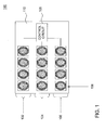
- FIG. 1 illustrates one embodiment of a lighting apparatus 100 of the present invention.
- the lighting apparatus comprises a plurality of LED groups 102, 104 and 106.
- Each of the plurality of LED groups 102, 104 and 106 may be coupled to at least one control circuit 105 on a single circuit board 110 or may be coupled to separate circuit boards 110.
- the control circuit 105 may comprise a controller (e. g. , a central processing unit (CPU) and associated computer readable mediums, e. g. , RAM, ROM, hard disk drive, floppy disk and the like for storing instructions) and one or more switches for controlling the LED groups 102, 104 and 106 independently.
- a controller e. g. , a central processing unit (CPU) and associated computer readable mediums, e. g. , RAM, ROM, hard disk drive, floppy disk and the like for storing instructions
- switches for controlling the LED groups 102, 104 and 106 independently.
- control circuit 105 may comprise ancillary devices such as wiring, resistors, capacitors, inductors, gates and the like designed and implemented to control each of the plurality of LED groups 102, 104 and 106 independently.
- ancillary devices such as wiring, resistors, capacitors, inductors, gates and the like designed and implemented to control each of the plurality of LED groups 102, 104 and 106 independently.
- any type of circuit design may be used to independently control the plurality of LED groups 102, 104 and 106 independently.
- FIG. 7 illustrates a block diagram of one example of a control circuit 105.
- the control circuit 105 may include a power source 702, a power supply 704, a LED current control 706, an external control signal module 708, a primary processing and control module 710, a feedback and monitoring module 712 and a feedback processing module 714.
- the LED current control 706 may be coupled to each one of the plurality of LED groups 102, 104 and 106.
- the feedback and monitoring module 712 may monitor various data via circuits 718 and 720 from each of the LED groups 102, 104 and 106. For example circuits 718 may provide LED temperature information and circuits 720 may provide current information.
- the external control signal module 708 and the primary processing and control module 710 may communicate with one another via two way communications represented by arrows 716.
- the external control signal module may be, for example, an external sensor as discussed below with respect to FIG. 5 .
- One exemplary detailed circuit diagram of the above control circuit 105 is illustrated by circuit 800 in FIG. 8 .
- each one of the plurality of LED groups 102, 104 and 106 may include at least one LED 108.
- the LED 108 may be any type of LED 108 that has enough light output to illuminate an outdoor area.
- the LED 108 may provide illuminance (lux) of at least 10 lumens per square meter or luminance (cd/m 2 ) of at least 1 candela per square meter.
- FIG. 1 illustrates that LED group 102 has 4 LEDs 108, LED group 104 has 4 LEDs 108 and that LED group 106 has 4 LEDs 108.
- LED group 102 has 4 LEDs 108
- LED group 104 has 4 LEDs 108
- LED group 106 has 4 LEDs 108.
- any number of LEDs 108 may be included in each LED group and the present invention is not limited to any specific number of LEDs 108.
- FIG. 1 illustrates that LED group 102 has 4 LEDs 108
- LED group 104 has 4 LEDs 108
- LED group 106 has 4 LEDs 108.
- any number of LEDs 108 may be included in each LED group and the present invention is not limited to any specific number of LEDs 108.
- three LED groups 102, 104 and 106 are illustrated in FIG. 1 , those skilled in the art will recognize that any number of LED groups may be used.
- each one of the plurality of LED groups 102, 104 and 106 may be independently controlled. That is, an illumination level of the LED 108 of any one of the LED groups 102, 104 or 106 may be adjusted without adjusting an illumination level of the other LED groups. For example, the illumination level of the LEDs 108 on LED group 102 may be adjusted without adjusting the illumination level of the LEDs 108 on the remaining LED groups 104 and 106. Illumination level may be defined herein as including on (ie, fully on), off and any gradation of illumination between on and off.
- the plurality of LED groups 102, 104 and 106 are included in a single lighting apparatus 100.
- a single lighting apparatus 100 needs to be powered to independently control three different LED groups 102, 104 and 106 as opposed to installing, and separately powering, three separate light fixtures to illuminate three different zones.
- only a single lighting apparatus 100 needs to be installed, thus saving time and labor costs for installation.
- FIG. 2 illustrates one embodiment of how the lighting apparatus 100 may be used to illuminate different zones 202, 204 and 206 of a surface 208.
- Each one of the LED groups 102, 104 and 106 may be associated with a different zone 202, 204 and 206.
- the LEDs 108 in LED group 102 may be positioned or configured such that when LED group 102 is activated only zone 202 is illuminated.
- the LEDs 108 in LED group 104 may be positioned or configured such that when LED group 104 is activated only zone 204 is illuminated.
- the LEDs 108 in the LED group 106 may be similarly arranged such that only zone 206 is illuminated when LED group 106 is activated.
- light emitted from the LEDs 108 of each one of the plurality of LED groups 102, 104 and 106 are emitted at a different angle or a different direction. That is, light emitted from LEDs 108 of LED group 102 are emitted at a different angle than light emitted from LEDs 108 of LED groups 104 and 106, respectively. There may be some overlap between the illumination zones, however a majority of the peak illumination of the LEDs 108 of each one of the LED groups 102, 104 and 106 falls within their respective zones, 202, 204 and 206. Said another way, in one embodiment, the light emitted from the LEDs 108 of each one of the plurality of LED groups 102, 104 and 106 are not in a parallel direction.
- each one of the LEDs 108 may face in a different direction to illuminate a respective zone 202, 204 and 206
- the LEDs 108 of each one of the plurality LED groups 102, 104 and 106 may all face the same direction and an optical component may be coupled to the LEDs 108 to re-direct the light emitted from the LEDs 108 in different angles or in different directions. This is illustrated as one embodiment in FIG. 3 .
- FIG. 3 illustrates one embodiment of the light apparatus 100 having LEDs 108 fitted with optical components 302, 304 and 306.
- the optical components 302, 304 and 306 may be a lens or a reflector. The optical components may be designed to move light output by the LEDs 108 or a LED group 102, 104 or 106 in a desired direction.
- the optical components 302, 304 and 306 may be the same for each of the LEDs 108 or each of the LED groups 102, 104 and 106 or may be different for each of the LEDs 108 or each of the LED groups 102, 104 and 106.
- each one of the LEDs 108 in LED group 102 may be fitted with a first optical component 302.
- Each one of the LEDs 108 in LED group 104 may be fitted with a second optical component 304.
- Each one of the LEDs 108 in LED group 106 may be fitted with a third optical component 306.
- a first optical component 302 may be coupled to the circuit board 110 of the LED group 102. In other words, a single first optical component 302 may be used to cover all of the LEDs 108 of the
- LED group 102 rather than individually coupling the first optical component 302 to each one of the LEDs 108 of the LED group 102. Similar configurations may be made with the second optical component 304 and the LEDs 108 of the LED group 104 and the third optical component 306 and the LEDs 108 of the LED group 106.
- the lighting apparatus 100 when the lighting apparatus 100 is manufactured, all of the LEDs 108 may be placed facing the same direction. Then using the optical components 302, 304 and 306, light emitted from the LEDs 108 may be redirected to illuminate a particular zone associated with a respective LED group 102, 104 or 106.
- the first optical component 302 may be used to re-direct light emitted from LEDs 108 in the LED group 102 towards zone 202.
- the second optical component 304 and the third optical components 306 may function similarly to illuminate zones 204 and 206, respectively.
- external sensors may be deployed to activate a particular LED group when the sensor is triggered.
- a sensor may be remotely deployed in each illumination zone and be in communication with one of the plurality of LED groups 102, 104 and 106.
- the sensor may be either wirelessly in communication with or directly wired to one of the plurality of LED groups 102, 104 and 106.
- Any type of sensor may be used to detect motion or the presence of a person or physical object such as, for example, a motion sensor, an induction loop, RADAR, a proximity sensor, an acoustic sensor, a pressure sensor and the like.
- FIGs. 4a-4c illustrate one embodiment of how sensors may be used to activate a particular LED group 102, 104 or 106 for multi-zoned illumination.
- FIG. 4a illustrates one of many possible applications of the lighting apparatus 100.
- a parking garage is used as one possible application.
- the lighting apparatus 100 may be installed over the surface 208.
- no persons or objects are detected by the sensors (not shown). Consequently, all of the LEDs 108 of the respective ones of the plurality of LED groups 102, 104 and 106 are turned off or are dimmed to the lowest illumination level.
- a person or object 400 is detected in zone 204.
- a person could be entering their parked car in zone 204 or a car could be approaching zone 204 in the parking garage.
- the information may be communicated to a particular LED group in the lighting apparatus 100.
- a particular LED group associated with zone 204 may be activated.
- the LED group 104 may be associated with the sensor in zone 204.
- an illumination level of the LEDs 108 in the LED group 104 may be adjusted to illuminate zone 204. For example, if the LEDs 108 in the LED group 104 were off, the LEDs 108 in the LED group 104 may be turned on and adjusted to a desired or pre-determined illumination level.
- different illumination levels may be used depending on whether a person or a vehicle is detected in zone 204. For example, when a person is detected in zone 204, the LEDs 108 in the LED group 104 may be adjusted to a maximum illumination level. Alternatively, when a car is detected in zone 204, the LEDs 108 in the LED group 104 may be adjusted to a lower illumination for energy and cost savings as the car will typically have headlights and full illumination is not needed.
- the sensor may distinguish the difference between a person and a car based upon a speed at which the object is moving or via image recognition methods. However, those skilled in the art will recognize that other methods may be used to differentiate between people and objects.
- the illumination level of the LEDs 108 in the LED group 104 is adjusted, the remaining LED groups 102 and 106 remain unchanged. That is, the illumination level of the LEDs 108 in the LED group 104 is independently controlled with respect to the other LED groups 102 and 106.
- a second person or object 402 is detected in zone 202.
- a car could be detected in zone 202 of the parking garage.
- the information may be communicated to a particular LED group in the lighting apparatus 100.
- a particular LED group associated with zone 202 may be activated.
- the LED group 102 may be associated with the sensor in zone 202.
- triggering the sensor in zone 202 activates the LED group 102.
- an illumination level of the LEDs 108 in the LED group 102 may be adjusted to illuminate zone 202. For example, if the LEDs 108 in the LED group 102 were off, the LEDs 108 in the LED group 102 may be turned on and adjusted to a desired or pre-determined illumination level.
- adjusting the illumination level of the LEDs 108 in the LED group 102 has no effect on the LEDs 108 in the LED groups 104 and 106, respectively.
- the LEDs 108 in the LED group 104 remain illuminated while object 400 is still in zone 204.
- the LEDs 108 in the LED group 106 remain off or in the lowest illumination setting while no person or object is detected in zone 206.
- the illumination level of the LED groups 102 and 104 may be different.
- FIGs. 4a-4c are discussed with respect to using the lighting apparatus 100 in a parking garage, those skilled in the art will recognize that the lighting apparatus 100 may be used in other environments.
- the lighting apparatus 100 may be used as street lighting or to light walkways.
- the environments discussed herein should only be viewed as examples and not be considered limiting the present invention.
- FIG. 5 illustrates a system 500 for providing multiple points of multi-zoned illumination.
- the system 500 illustrated in FIG. 5 may be utilized on a street with multiple lanes of traffic.
- Each one of the plurality of LED groups in the lighting apparatus 100 may be used to illuminate a single lane of traffic.
- a plurality of lighting apparatuses 100 may be situated along a street each having the plurality of LED groups to selectively illuminate lanes of traffic along a street as needed.
- Each one of the plurality of lighting apparatuses 100 may each have one or more sensors 502.
- the sensor 502 may be an external sensor remotely located form a respective lighting apparatus 100 and in communication with the respective lighting apparatus 100.
- a sensor 502 may be placed in each lane and in communication with a respective one of the plurality of LED groups.
- an induction loop 510 may be used in each lane and in communication with a respective one of the plurality of LED groups.
- a different type of sensor may be used in each lane.
- a LED group associated with the sensor 502 or induction loop 510 may be activated.
- LEDs associated with the activated LED group may illuminate the lane having the passing car, while the LEDs associated with the remaining LED groups in the unused lanes remain off or at a minimum illumination level.
- the sensor 502 or the induction loop 510 may be placed a calculated distance before the lighting apparatuses 100 such that a first lighting apparatus 100 may have enough time to receive communications from the sensor 502 or the induction loop 510 and activate the LEDs of an appropriate LED group.
- the distance may be based upon an average speed of cars using the street and the amount of time for the lighting apparatuses 100 to receive communications and activate the LEDs of an appropriate LED group.
- the plurality of lighting apparatuses 100 may be in communication with one another.
- the plurality of lighting apparatuses 100 may communicate using radio frequency (RF) point-to-point communications. This may be used to communicate information between the plurality of lighting apparatuses 100 such that they may activate LEDs down the road for the particular lane as the car is moving.
- RF radio frequency
- a first sensor 502 or induction loop 510 detects a passing car, thereby activating LEDs of a particular LED group of a first lighting apparatus 100. Subsequently, the first lighting apparatus 100 may communicate with a second lighting apparatus 100 down the street informing it that a car is approaching. Thus, the second lighting apparatus 100 may activate a particular LED group associated with the same lane as illuminated by the particular LED group in the first lighting apparatus 100 in anticipation of the approaching car. This may then be repeated again by having the second lighting apparatus 100 send a communications to a third lighting apparatus 100 and so forth.
- a sensor 502 or an induction loop 510 need not be placed with every one of the plurality of lighting apparatuses 100.
- a sensor 502 or an induction loop 510 may be placed every 10 lighting apparatuses to ensure the car is still in the illuminated lane. However, if the car turns off of the street before the next sensor, then the subsequent plurality of lighting apparatuses 100 down the street would not be activated.
- logic may be implemented to turn off the plurality of lighting apparatuses 100 after they are turned on. For example, if the first lighting apparatus 100 is turned on and the first sensor 502 does not detect a passing car within a predefined period of time, the lighting apparatus 100 may automatically turn off. Alternatively, if a second sensor (not shown) detects the passing car at a second lighting apparatus, then the second sensor may communicate back to the first lighting apparatus 100 to instruct the first lighting apparatus 100 to turn off. Those skilled in the art will recognize that any logic may be implemented to turn off the plurality of lighting apparatuses 100 after they are turned on.
- the plurality of lighting apparatuses 100 may also be in communication with a remotely located central controller 504 via a hub 506.
- the central controller 504 may comprise a processor element (e.g., a CPU), a memory, e.g., random access memory (RAM) and/or read only memory (ROM) and various input/output devices (e.g., computer readable mediums or storage devices, including but not limited to, a tape drive, a floppy drive, a hard disk drive or a compact disk drive, a receiver, a transmitter, a speaker, a display, a speech synthesizer, an output port, and a user input device (such as a keyboard, a keypad, a mouse, alarm interfaces, power relays and the like)).
- a processor element e.g., a CPU
- RAM random access memory
- ROM read only memory
- various input/output devices e.g., computer readable mediums or storage devices, including but not limited to, a tape drive,
- the central controller 504 may communicate with the hub 506 via a global system for mobile (GSM) communications network.
- GSM global system for mobile
- the hub 506 may communicate with the plurality of lighting apparatuses 100 via RF point-to-point communications.
- a mobile node 508 may also be used to communicate with the plurality of lighting apparatuses 100 via the hub 506.
- the mobile node 508 may communicate with the hub 506 via a short message service (SMS) protocol.
- SMS short message service
- the central controller 504 and/or the mobile node 508 may be used to monitor and/or control each one of the plurality of lighting apparatuses 100. For example, if maintenance needs to be performed on one of the plurality of lighting apparatuses 100, the central controller 504 may be used to temporarily disable the lighting apparatus 100. Alternatively, the central controller 504 may be used to ensure the plurality of lighting apparatuses 100 remain turned on if emergency personnel are present or there is an accident. The central controller 504 may also be used to collect information from each of the plurality of lighting apparatuses 100 such as life, power readings, status, error alarms, etc. Thus, the system 500 provides an integrated communications network of the plurality of lighting apparatuses 100.
- one or more thresholds may be used by the sensors and the lighting apparatuses 100.
- the sensor may only activate one of the plurality of LED groups in the lighting apparatus 100 if an object is moving above a certain speed, e.g. around the speed limit associated with the street.
- the above embodiment may provide substantial cost savings for street lighting.
- the lights may remain off until a moving car or object is detected rather than having the lights remain on throughout the light when the street is not in use.
- FIG. 6 illustrates one embodiment of a flow chart for a method 600 for providing multi-zoned illumination using a single lighting apparatus.
- the method 600 begins at step 602.
- the method 600 powers a single lighting apparatus having a plurality of LED groups, each one of the plurality of LED groups having at least one LED.
- a single power source to a single lighting apparatus for illuminating multiple zones.
- the method 600 controls each one of the plurality of LED groups independently of one another via a respective external sensor that controls a respective one of said plurality of LED groups when triggered. As described above, even though the single lighting apparatus 100 is powered, all of the LEDs in the lighting apparatus 100 need not be all at the same illumination level. Notably, the LEDs may be associated with different LED groups and adjusted or powered on or off independently of the other LED groups.
- the method 600 concludes at step 608.
Landscapes
- Engineering & Computer Science (AREA)
- Computer Networks & Wireless Communication (AREA)
- Circuit Arrangement For Electric Light Sources In General (AREA)
Description
- The present invention is directed to a lighting apparatus and more specifically to a single lighting apparatus having a plurality of LED groups for multi-zoned LED based illumination.
- Current exterior lighting, such as for example street lights, using fluorescent tubes or mercury metal is inefficient and has several drawbacks. They generally consume more power and have a relatively short life. One alternative approach is to replace these light sources with light emitting diode (LED) based exterior lighting.
- However, current LED based solutions use multiple LEDs to provide a required amount of lumens to illuminate a surface. Moreover, the LEDs are not independently controllable. That is, all of the LEDs must be adjusted at the same time.
-
US 200/0174472 proposes LED methods and systems for photographic and cinematography applications. Controlled LED illumination allows easy customization of these features to create a particular mood, and can be used to create light of desired saturation and hue. -
US 2006/0076908 proposes lighting networks that include multiple LED-based lighting units, and user interfaces to facilitate control of such networks. It proposes that lighting units of a lighting network may be configured to generate one or more of variable color light, variable intensity light, and variable color temperature white light. -
US 7471051 proposes a low voltage lighting system supporting multiple independently controlled zones utilizing a plurality of semiconductor switches coupled to a plurality of transformers to produce a non-sinusoidal power output, and controlled by a digital controller that receives feedback from each zone in order to auto-sense the proper voltage for a plurality of connected loads. -
US 4924151 proposes a system for controlling power to multiple groups of lights that requires only a few controls. The system permits power to each group of lights to be adjusted independently and, at the same time, to be stored for later recall. Several combinations of power levels can be stored, and a particular combination can be selected, for example, by pressing a corresponding push button. In a preferred embodiment, a single control permits adjustment of any selected group, or groups, of lights. -
US 6046550 proposes a diagnostic apparatus for use in a light dimming circuit which selectively controls the current flow through a lighting load to adjust its luminous output. The dimming circuit has a controllably conductive device, such as a triac, connectable in series between an A.C. power source and a lighting load, and a control circuit which responds to a dimming level control signal to selectively apply a selected portion of an A.C. voltage waveform produced by the A.C. power source to the lighting load to adjust the RMS voltage across the load. The selected portion is determined by a firing angle at which the control circuit causes the controllably conductive device to conduct power during each half cycle of the A.C. waveform. - The present invention is directed to a multi-zoned lighting apparatus. One aspect of the invention provides a multi-zoned lighting apparatus comprising: at least one circuit board; at least one control circuit coupled to said at least one circuit board; and a plurality of light emitting diode (LED) groups coupled to said at least one control circuit and the at least one circuit board, wherein each LED group of said plurality of LED groups has at least one LED and wherein each LED group of said plurality of LED groups is independently controlled via said at least one control circuit based on a respective external signal received by said at least one control circuit from a respective external sensor; characterised in that said at least one control circuit is adapted to receive an external signal indicating that said respective external sensor associated with said respective one of said plurality of LED groups has been triggered by detecting an object; and in that an illumination level of said respective one of said plurality of LED groups is controlled by the at least one control circuit based on a type of object that is detected by said respective external sensor, a highest illumination level being used when said type of object detected is a person and an illumination level lower than said highest illumination level being used when said type of object detected is a vehicle.
- A further aspect of the invention provides a corresponding method.
- A further aspect of the invention provides a system for providing multiple points of multi-zoned illumination, the system comprising: a plurality of lighting apparatuses of the first aspect; at least one sensor coupled to the at least one control circuit of each one of said plurality of lighting apparatuses; and a central controller remotely located from said plurality of lighting apparatuses and in communication with said plurality of lighting apparatuses.
- So that the manner in which the above recited features of the present invention can be understood in detail, a more particular description of the invention, may be had by reference to embodiments, some of which are illustrated in the appended drawings, It is to be noted, however, that the appended drawings illustrate only typical embodiments of this invention and are therefore not to be considered limiting of its scope, for the invention may admit to other equally effective embodiments.
-
FIG. 1 depicts one embodiment of a single lighting apparatus having a plurality of LED groups; -
FIG. 2 depicts one embodiment of the single lighting apparatus used to illuminate different zones; -
FIG. 3 depicts one embodiment of the single lighting apparatus having different optical components fitted to the tight emitting diodes (LEDs); -
FIG. 4a depicts one embodiment of the single light apparatus when all illumination zones are off; -
FIG. 4b depicts one embodiment of the single light apparatus when a first sensor is triggered; -
FIG. 4c depicts one embodiment of the single light apparatus when a second sensor is triggered; -
FIG. 5 depicts one embodiment of a system for providing multiple points of multi-zoned illumination; -
FIG. 6 depicts a flow chart for one embodiment of a method for providing multi-zoned illumination using a single lighting apparatus; -
FIG. 7 depicts a block diagram of one example of a control circuit for the single lighting apparatus having a plurality of LED groups; and -
FIGs. 8A and8B depict a circuit diagram of one example of the control circuit. - To facilitate understanding, identical reference numerals have been used, where possible, to designate identical elements that are common to the figures.
- Embodiments of the present invention resolve the above noted problems associated with previously used lighting apparatuses for exterior lighting. For example, in one embodiment, the present invention uses a single light emitting diode (LED) based lighting apparatus having a plurality of independently controlled LED groups for multi-zoned illumination. Thus, the present invention provides a more efficient and cost effective option for exterior lighting. For example, various LED groups may be turned off or dimmed to a low setting until a person or object (e.g., a automobile, motorcycle and the like) is detected. Then, only a LED group associated with the zone that detected the person or object may be activated. Thus, costs savings is achieved by only powering up particular LED groups in the single lighting apparatus on an "as-needed" basis.
-
FIG. 1 illustrates one embodiment of alighting apparatus 100 of the present invention. The lighting apparatus comprises a plurality ofLED groups LED groups control circuit 105 on asingle circuit board 110 or may be coupled to separatecircuit boards 110. In one embodiment, thecontrol circuit 105 may comprise a controller (e. g. , a central processing unit (CPU) and associated computer readable mediums, e. g. , RAM, ROM, hard disk drive, floppy disk and the like for storing instructions) and one or more switches for controlling theLED groups control circuit 105 may comprise ancillary devices such as wiring, resistors, capacitors, inductors, gates and the like designed and implemented to control each of the plurality ofLED groups LED groups -
FIG. 7 illustrates a block diagram of one example of acontrol circuit 105. Thecontrol circuit 105 may include apower source 702, apower supply 704, aLED current control 706, an externalcontrol signal module 708, a primary processing andcontrol module 710, a feedback andmonitoring module 712 and afeedback processing module 714. The LEDcurrent control 706 may be coupled to each one of the plurality ofLED groups monitoring module 712 may monitor various data viacircuits LED groups example circuits 718 may provide LED temperature information andcircuits 720 may provide current information. - In one embodiment, the external
control signal module 708 and the primary processing andcontrol module 710 may communicate with one another via two way communications represented byarrows 716. The external control signal module may be, for example, an external sensor as discussed below with respect toFIG. 5 . One exemplary detailed circuit diagram of theabove control circuit 105 is illustrated bycircuit 800 inFIG. 8 . - Referring back to
FIG. 1 , each one of the plurality ofLED groups LED 108. In one embodiment, theLED 108 may be any type ofLED 108 that has enough light output to illuminate an outdoor area. For example, theLED 108 may provide illuminance (lux) of at least 10 lumens per square meter or luminance (cd/m2) of at least 1 candela per square meter. -
FIG. 1 illustrates thatLED group 102 has 4LEDs 108,LED group 104 has 4LEDs 108 and thatLED group 106 has 4LEDs 108. Those skilled in the art will recognize that any number ofLEDs 108 may be included in each LED group and the present invention is not limited to any specific number ofLEDs 108. In addition, although only threeLED groups FIG. 1 , those skilled in the art will recognize that any number of LED groups may be used. - In one embodiment, each one of the plurality of
LED groups LED 108 of any one of theLED groups LEDs 108 onLED group 102 may be adjusted without adjusting the illumination level of theLEDs 108 on the remainingLED groups - Notably, the plurality of
LED groups single lighting apparatus 100. Thus, only asingle lighting apparatus 100 needs to be powered to independently control threedifferent LED groups single lighting apparatus 100 needs to be installed, thus saving time and labor costs for installation. - The ability to independently control the plurality of
LED groups FIG. 2 illustrates one embodiment of how thelighting apparatus 100 may be used to illuminatedifferent zones surface 208. - Each one of the
LED groups different zone LEDs 108 inLED group 102 may be positioned or configured such that whenLED group 102 is activated onlyzone 202 is illuminated. Accordingly, theLEDs 108 inLED group 104 may be positioned or configured such that whenLED group 104 is activated onlyzone 204 is illuminated. TheLEDs 108 in theLED group 106 may be similarly arranged such thatonly zone 206 is illuminated whenLED group 106 is activated. - Notably, light emitted from the
LEDs 108 of each one of the plurality ofLED groups LEDs 108 ofLED group 102 are emitted at a different angle than light emitted fromLEDs 108 ofLED groups LEDs 108 of each one of theLED groups LEDs 108 of each one of the plurality ofLED groups - In one embodiment, rather than positioning each one of the
LEDs 108 to face in a different direction to illuminate arespective zone LEDs 108 of each one of theplurality LED groups LEDs 108 to re-direct the light emitted from theLEDs 108 in different angles or in different directions. This is illustrated as one embodiment inFIG. 3 . -
FIG. 3 illustrates one embodiment of thelight apparatus 100 havingLEDs 108 fitted withoptical components optical components LEDs 108 or aLED group optical components LEDs 108 or each of theLED groups LEDs 108 or each of theLED groups LEDs 108 inLED group 102 may be fitted with a firstoptical component 302. Each one of theLEDs 108 inLED group 104 may be fitted with a secondoptical component 304. Each one of theLEDs 108 inLED group 106 may be fitted with a thirdoptical component 306. - In an alternative embodiment, a first
optical component 302 may be coupled to thecircuit board 110 of theLED group 102. In other words, a single firstoptical component 302 may be used to cover all of theLEDs 108 of the -
LED group 102, rather than individually coupling the firstoptical component 302 to each one of theLEDs 108 of theLED group 102. Similar configurations may be made with the secondoptical component 304 and theLEDs 108 of theLED group 104 and the thirdoptical component 306 and theLEDs 108 of theLED group 106. - Thus, when the
lighting apparatus 100 is manufactured, all of theLEDs 108 may be placed facing the same direction. Then using theoptical components LEDs 108 may be redirected to illuminate a particular zone associated with arespective LED group FIG. 2 , the firstoptical component 302 may be used to re-direct light emitted fromLEDs 108 in theLED group 102 towardszone 202. The secondoptical component 304 and the thirdoptical components 306 may function similarly to illuminatezones - In one embodiment, external sensors (not shown) may be deployed to activate a particular LED group when the sensor is triggered. A sensor may be remotely deployed in each illumination zone and be in communication with one of the plurality of
LED groups LED groups -
FIGs. 4a-4c illustrate one embodiment of how sensors may be used to activate aparticular LED group -
FIG. 4a illustrates one of many possible applications of thelighting apparatus 100. InFIG. 4a a parking garage is used as one possible application. Thelighting apparatus 100 may be installed over thesurface 208. As illustrated inFIG. 4a , no persons or objects are detected by the sensors (not shown). Consequently, all of theLEDs 108 of the respective ones of the plurality ofLED groups - In
FIG. 4b , a person or object 400 is detected inzone 204. For example, a person could be entering their parked car inzone 204 or a car could be approachingzone 204 in the parking garage. In any case, when the person or object 400 triggers a sensor inzone 204, the information may be communicated to a particular LED group in thelighting apparatus 100. Thus, a particular LED group associated withzone 204 may be activated. In the present example, theLED group 104 may be associated with the sensor inzone 204. - Thus, triggering the sensor associated with
zone 204 activates theLED group 104. As a result, an illumination level of theLEDs 108 in theLED group 104 may be adjusted to illuminatezone 204. For example, if theLEDs 108 in theLED group 104 were off, theLEDs 108 in theLED group 104 may be turned on and adjusted to a desired or pre-determined illumination level. - In one embodiment, different illumination levels may be used depending on whether a person or a vehicle is detected in
zone 204. For example, when a person is detected inzone 204, theLEDs 108 in theLED group 104 may be adjusted to a maximum illumination level. Alternatively, when a car is detected inzone 204, theLEDs 108 in theLED group 104 may be adjusted to a lower illumination for energy and cost savings as the car will typically have headlights and full illumination is not needed. In one embodiment, the sensor may distinguish the difference between a person and a car based upon a speed at which the object is moving or via image recognition methods. However, those skilled in the art will recognize that other methods may be used to differentiate between people and objects. - Notably, in
FIG. 4b , while the illumination level of theLEDs 108 in theLED group 104 is adjusted, the remainingLED groups LEDs 108 in theLED group 104 is independently controlled with respect to theother LED groups - Referring now to
FIG. 4c , a second person or object 402 is detected inzone 202. For example, a car could be detected inzone 202 of the parking garage. When the person or object 402 triggers a sensor inzone 202, the information may be communicated to a particular LED group in thelighting apparatus 100. Thus, a particular LED group associated withzone 202 may be activated. In the present example, theLED group 102 may be associated with the sensor inzone 202. - Thus, triggering the sensor in
zone 202 activates theLED group 102. As a result, an illumination level of theLEDs 108 in theLED group 102 may be adjusted to illuminatezone 202. For example, if theLEDs 108 in theLED group 102 were off, theLEDs 108 in theLED group 102 may be turned on and adjusted to a desired or pre-determined illumination level. - Notably, adjusting the illumination level of the
LEDs 108 in theLED group 102 has no effect on theLEDs 108 in theLED groups LEDs 108 in theLED group 104 remain illuminated whileobject 400 is still inzone 204. In addition, theLEDs 108 in theLED group 106 remain off or in the lowest illumination setting while no person or object is detected inzone 206. Moreover, the illumination level of theLED groups - Although
FIGs. 4a-4c are discussed with respect to using thelighting apparatus 100 in a parking garage, those skilled in the art will recognize that thelighting apparatus 100 may be used in other environments. For example, thelighting apparatus 100 may be used as street lighting or to light walkways. Thus, the environments discussed herein should only be viewed as examples and not be considered limiting the present invention. - The
lighting apparatus 100 may be used withother lighting apparatuses 100 to form a more complicated system.FIG. 5 illustrates asystem 500 for providing multiple points of multi-zoned illumination. For example, thesystem 500 illustrated inFIG. 5 may be utilized on a street with multiple lanes of traffic. Each one of the plurality of LED groups in thelighting apparatus 100 may be used to illuminate a single lane of traffic. A plurality oflighting apparatuses 100 may be situated along a street each having the plurality of LED groups to selectively illuminate lanes of traffic along a street as needed. - Each one of the plurality of
lighting apparatuses 100 may each have one ormore sensors 502. As discussed above, thesensor 502 may be an external sensor remotely located form arespective lighting apparatus 100 and in communication with therespective lighting apparatus 100. Asensor 502 may be placed in each lane and in communication with a respective one of the plurality of LED groups. Alternatively, aninduction loop 510 may be used in each lane and in communication with a respective one of the plurality of LED groups. In yet another embodiment, a different type of sensor may be used in each lane. - When the
sensor 502 or theinduction loop 510 in a lane of the street senses a passing car, a LED group associated with thesensor 502 orinduction loop 510 may be activated. Thus, LEDs associated with the activated LED group may illuminate the lane having the passing car, while the LEDs associated with the remaining LED groups in the unused lanes remain off or at a minimum illumination level. In one embodiment, thesensor 502 or theinduction loop 510 may be placed a calculated distance before thelighting apparatuses 100 such that afirst lighting apparatus 100 may have enough time to receive communications from thesensor 502 or theinduction loop 510 and activate the LEDs of an appropriate LED group. For example, the distance may be based upon an average speed of cars using the street and the amount of time for thelighting apparatuses 100 to receive communications and activate the LEDs of an appropriate LED group. - Moreover, the plurality of
lighting apparatuses 100 may be in communication with one another. In one embodiment, the plurality oflighting apparatuses 100 may communicate using radio frequency (RF) point-to-point communications. This may be used to communicate information between the plurality oflighting apparatuses 100 such that they may activate LEDs down the road for the particular lane as the car is moving. - To illustrate, a
first sensor 502 orinduction loop 510 detects a passing car, thereby activating LEDs of a particular LED group of afirst lighting apparatus 100. Subsequently, thefirst lighting apparatus 100 may communicate with asecond lighting apparatus 100 down the street informing it that a car is approaching. Thus, thesecond lighting apparatus 100 may activate a particular LED group associated with the same lane as illuminated by the particular LED group in thefirst lighting apparatus 100 in anticipation of the approaching car. This may then be repeated again by having thesecond lighting apparatus 100 send a communications to athird lighting apparatus 100 and so forth. - As a result, a
sensor 502 or aninduction loop 510 need not be placed with every one of the plurality oflighting apparatuses 100. For example, asensor 502 or aninduction loop 510 may be placed every 10 lighting apparatuses to ensure the car is still in the illuminated lane. However, if the car turns off of the street before the next sensor, then the subsequent plurality oflighting apparatuses 100 down the street would not be activated. - Other types of logic may be implemented to turn off the plurality of
lighting apparatuses 100 after they are turned on. For example, if thefirst lighting apparatus 100 is turned on and thefirst sensor 502 does not detect a passing car within a predefined period of time, thelighting apparatus 100 may automatically turn off. Alternatively, if a second sensor (not shown) detects the passing car at a second lighting apparatus, then the second sensor may communicate back to thefirst lighting apparatus 100 to instruct thefirst lighting apparatus 100 to turn off. Those skilled in the art will recognize that any logic may be implemented to turn off the plurality oflighting apparatuses 100 after they are turned on. - The plurality of
lighting apparatuses 100 may also be in communication with a remotely locatedcentral controller 504 via ahub 506. In one embodiment, thecentral controller 504 may comprise a processor element (e.g., a CPU), a memory, e.g., random access memory (RAM) and/or read only memory (ROM) and various input/output devices (e.g., computer readable mediums or storage devices, including but not limited to, a tape drive, a floppy drive, a hard disk drive or a compact disk drive, a receiver, a transmitter, a speaker, a display, a speech synthesizer, an output port, and a user input device (such as a keyboard, a keypad, a mouse, alarm interfaces, power relays and the like)). - In one embodiment, the
central controller 504 may communicate with thehub 506 via a global system for mobile (GSM) communications network. Thehub 506 may communicate with the plurality oflighting apparatuses 100 via RF point-to-point communications. - In one embodiment a
mobile node 508 may also be used to communicate with the plurality oflighting apparatuses 100 via thehub 506. For example, themobile node 508 may communicate with thehub 506 via a short message service (SMS) protocol. - In one embodiment, the
central controller 504 and/or themobile node 508 may be used to monitor and/or control each one of the plurality oflighting apparatuses 100. For example, if maintenance needs to be performed on one of the plurality oflighting apparatuses 100, thecentral controller 504 may be used to temporarily disable thelighting apparatus 100. Alternatively, thecentral controller 504 may be used to ensure the plurality oflighting apparatuses 100 remain turned on if emergency personnel are present or there is an accident. Thecentral controller 504 may also be used to collect information from each of the plurality oflighting apparatuses 100 such as life, power readings, status, error alarms, etc. Thus, thesystem 500 provides an integrated communications network of the plurality oflighting apparatuses 100. - In one embodiment, to prevent inadvertently triggering the sensors by animals or flying debris, one or more thresholds may be used by the sensors and the
lighting apparatuses 100. For example, the sensor may only activate one of the plurality of LED groups in thelighting apparatus 100 if an object is moving above a certain speed, e.g. around the speed limit associated with the street. - Notably, the above embodiment may provide substantial cost savings for street lighting. For example, in rural roads that are infrequently travelled, the lights may remain off until a moving car or object is detected rather than having the lights remain on throughout the light when the street is not in use.
-
FIG. 6 illustrates one embodiment of a flow chart for amethod 600 for providing multi-zoned illumination using a single lighting apparatus. Themethod 600 begins atstep 602. - At
step 604, themethod 600 powers a single lighting apparatus having a plurality of LED groups, each one of the plurality of LED groups having at least one LED. As discussed above, one embodiment of the present invention only requires a single power source to a single lighting apparatus for illuminating multiple zones. - At
step 606, themethod 600 controls each one of the plurality of LED groups independently of one another via a respective external sensor that controls a respective one of said plurality of LED groups when triggered. As described above, even though thesingle lighting apparatus 100 is powered, all of the LEDs in thelighting apparatus 100 need not be all at the same illumination level. Notably, the LEDs may be associated with different LED groups and adjusted or powered on or off independently of the other LED groups. Themethod 600 concludes atstep 608. - While various embodiments have been described above, it should be understood that they have been presented by way of example only, and not limitation. Thus, the scope of the present invention should not be limited by any of the above-described embodiments, but should be defined only in accordance with the following claims.
Claims (13)
- A multi-zoned single lighting apparatus (100) comprising:at least one circuit board (110);at least one control circuit (105) coupled to said at least one circuit board; anda plurality of light emitting diode, LED, groups (102,104,106) coupled to said at least one control circuit (105) and the at least one circuit board, wherein each LED group of said plurality of LED groups has at least one LED and wherein each LED group of said plurality of LED groups is adapted to be independently controlled via said at least one control circuit (105) based on a respective external signal (716) received by said at least one control circuit (105) from a respective external sensor (502, 510);characterised in that said at least one control circuit is adapted to receive said external signal as indicating that said respective external sensor associated with said respective one of said plurality of LED groups has been triggered by detecting an object;and in that an illumination level of said respective one of said plurality of LED groups is controlled by the at least one control circuit (105) based on a type of object that is detected by said respective external sensor, a highest illumination level being used when said type of object detected is a person and an illumination level lower than said highest illumination level being used when said type of object detected is a vehicle.
- The multi-zoned single lighting apparatus of claim 1, wherein each one of said plurality of LED groups (102,104,106) is adapted to illuminate a different zone (202,204,206).
- The multi-zoned single lighting apparatus of claim 1, wherein independently controlled comprises changing said illumination level of one of said plurality of LED groups without changing an illumination level of remaining ones of said plurality of LED groups.
- The multi-zoned single lighting apparatus of claim 1, wherein each one of said plurality of LED groups is adapted to provide at least 10 lumens per square meter.
- The multi-zoned single lighting apparatus of claim 1, further comprising:a controller (710) coupled to said respective external sensor.
- The multi-zoned single lighting apparatus of claim 1, wherein said at least one LED of each one of said plurality of LED groups is coupled to an optic (302, 304, 306).
- A method for providing multi-zoned illumination using a single lighting apparatus (100), the method comprising:powering said single lighting apparatus having a plurality of light emitting diode, LED, groups (102,104,106), each one of said plurality of LED groups having at least one LED; andcontrolling each one of said plurality of LED groups (102,104,106) independently of one another via a control circuit (105) that controls a respective one of said plurality of LED groups based on a respective external signal (716) from a respective external sensor (502,510);characterised in that said controlling comprises:receiving said external signal (716) as indicative of triggering of said respective external sensor associated with said respective one of said plurality of LED groups when said respective external sensor detects an object; anddetermining an illumination level of said respective one of said plurality of LED groups based on a type of object that has been detected by said respective external sensor, a highest illumination level being used when said type of object detected is a person and an illumination level lower than said highest illumination level being used when said type of object detected is a vehicle.
- The method of claim 7, wherein each one of said plurality of LED groups illuminates a different zone.
- A system (500) for providing multiple points of multi-zoned illumination, the system comprising:a plurality of lighting apparatuses (100), each one of the plurality of lighting apparatuses being a multi-zoned single lighting apparatus as defined in any one of claims 1 to 6;at least one sensor (502,510) coupled to the at least one control circuit of each one of said plurality of lighting apparatuses (100); anda central controller (504) remotely located from said plurality of lighting apparatuses and in communication with said plurality of lighting apparatuses.
- The system of claim 9, wherein each one of said plurality of lighting apparatuses is in communication with one another.
- The system of claim 10, wherein each one of said plurality of lighting apparatuses is adapted to communicate with one another via radio frequency.
- The system of claim 9, wherein each one of the plurality of LED groups in each one of said plurality of lighting apparatuses (100) is adapted to illuminate a different zone (202,204,206).
- The system of claim 9, further comprising:a hub (506) adapted to relay communications between said central controller (504) and each one of said plurality of lighting apparatuses (100), wherein one or more mobile devices (508) is adapted to communicate with said plurality of lighting apparatuses (100) via said hub (506).
Applications Claiming Priority (1)
| Application Number | Priority Date | Filing Date | Title |
|---|---|---|---|
| PCT/GB2009/050437 WO2010125325A1 (en) | 2009-04-28 | 2009-04-28 | Method and apparatus for multi-zoned illumination |
Publications (2)
| Publication Number | Publication Date |
|---|---|
| EP2425678A1 EP2425678A1 (en) | 2012-03-07 |
| EP2425678B1 true EP2425678B1 (en) | 2015-12-02 |
Family
ID=41528713
Family Applications (1)
| Application Number | Title | Priority Date | Filing Date |
|---|---|---|---|
| EP09785218.0A Active EP2425678B1 (en) | 2009-04-28 | 2009-04-28 | Method and apparatus for multi-zoned illumination |
Country Status (4)
| Country | Link |
|---|---|
| US (1) | US8901846B2 (en) |
| EP (1) | EP2425678B1 (en) |
| CA (1) | CA2760380C (en) |
| WO (1) | WO2010125325A1 (en) |
Families Citing this family (24)
| Publication number | Priority date | Publication date | Assignee | Title |
|---|---|---|---|---|
| EP2425678B1 (en) | 2009-04-28 | 2015-12-02 | Dialight Corporation | Method and apparatus for multi-zoned illumination |
| US8598986B2 (en) | 2009-04-28 | 2013-12-03 | Dialight Corporation | Remote monitoring and control of LED based street lights |
| US8803662B2 (en) | 2009-04-28 | 2014-08-12 | Dialight Corporation | Remote monitoring and control of LED based street lights |
| WO2012142447A1 (en) * | 2011-04-13 | 2012-10-18 | Amerlux, Llc | Directionally controllable street lamp |
| MX2014008213A (en) * | 2012-01-05 | 2014-11-25 | Bright Light Systems Inc | Systems and methods for providing high-mast lighting. |
| US8992056B2 (en) | 2012-02-03 | 2015-03-31 | I/O Controls Corporation | Vehicle headlight and alert system |
| US9445480B2 (en) * | 2012-04-12 | 2016-09-13 | Lg Electronics Inc. | Lighting system, lighting apparatus, and lighting control method |
| US9497829B2 (en) | 2012-05-02 | 2016-11-15 | Koninklijke Phillips N.V. | Methods for adaptively controlling lighting based upon traffic in an outdoor lighting network |
| US9310055B2 (en) | 2012-07-17 | 2016-04-12 | Koninklijke Philips N.V. | Lighting device, a method of controlling the same, for selectively emitting light along or against traffic direction |
| US9192026B2 (en) * | 2013-03-14 | 2015-11-17 | Abl Ip Holding Llc | Veiling zone control |
| US9192029B2 (en) * | 2013-03-14 | 2015-11-17 | Abl Ip Holding Llc | Adaptive optical distribution system |
| US9338850B2 (en) * | 2013-04-24 | 2016-05-10 | GE Lighting Solutions, LLC | Lighting systems and methods providing active glare control |
| US10568179B2 (en) * | 2013-09-20 | 2020-02-18 | Osram Sylvania Inc. | Techniques and photographical user interface for controlling solid-state luminaire with electronically adjustable light beam distribution |
| US9380684B2 (en) * | 2014-04-14 | 2016-06-28 | GE Lighting Solutions, LLC | Method and system for an electronically adaptive photometry for roadway lighting |
| US9520742B2 (en) | 2014-07-03 | 2016-12-13 | Hubbell Incorporated | Monitoring system and method |
| RU2698303C2 (en) * | 2014-09-08 | 2019-08-26 | Филипс Лайтинг Холдинг Б.В. | Conflict of lighting preferences resolution |
| US9877374B2 (en) * | 2014-11-25 | 2018-01-23 | Cree, Inc. | Lighting apparatus and methods providing variable illumination characteristics based on object detection |
| US10163343B2 (en) | 2015-02-23 | 2018-12-25 | GE Lighting Solutions, LLC | Remote control of light signaling devices |
| WO2017035858A1 (en) * | 2015-08-28 | 2017-03-09 | 顾建兵 | Energy-saving street lamp |
| GB2546116A (en) * | 2016-01-11 | 2017-07-12 | Infomode Ltd | Piezo strip activated vehicle lighting system |
| DE102019114526A1 (en) * | 2019-05-29 | 2020-12-03 | Bartenbach Holding Gmbh | lamp |
| EP3757310A1 (en) * | 2019-06-28 | 2020-12-30 | Saint-Gobain Ecophon AB | Ceiling system |
| CN114222406B (en) * | 2021-11-25 | 2024-05-17 | 深圳市明之辉智慧科技有限公司 | Urban illumination control method, device, equipment and storage medium |
| CN118973049B (en) * | 2024-08-20 | 2025-10-03 | 惠州市蓝微电子有限公司 | A control method, system and memory for sensing and transmitting based on radar sensing optimization and data synchronous communication |
Family Cites Families (54)
| Publication number | Priority date | Publication date | Assignee | Title |
|---|---|---|---|---|
| US3944723A (en) | 1974-12-05 | 1976-03-16 | General Electric Company | Station for power line access data system |
| IT1155545B (en) | 1982-05-18 | 1987-01-28 | Applic Elettrotelefoniche A E | DEVICE FOR REMOTE DETECTION OF BROKEN LAMP IN A LIGHTING SYSTEM WITH MULTIPLE PARALLEL LAMPS |
| FR2624335B1 (en) | 1987-12-04 | 1990-03-23 | Finzel Jean Luc | SELECTIVE DETECTION AND SIGNALING ASSEMBLY OF OPERATING FAULTS OF LIGHTING UNITS IN A LIGHTING NETWORK |
| US4924151A (en) | 1988-09-30 | 1990-05-08 | Lutron Electronics Co., Inc. | Multi-zone, multi-scene lighting control system |
| IT1260524B (en) | 1992-06-03 | 1996-04-09 | PROCEDURE FOR CHECKING THE OPERATING STATE OF LAMPS OF A PUBLIC LIGHTING NETWORK | |
| US5962991A (en) | 1996-06-27 | 1999-10-05 | Intelilite, L.L.C. | Intelligent outdoor lighting control system |
| US5811975A (en) | 1996-09-09 | 1998-09-22 | Bernardo; James Segura | Apparatus and method for electronic testing and monitoring of emergency luminare |
| JPH10234142A (en) | 1997-02-20 | 1998-09-02 | Nissho Seisakusho:Kk | Lighting monitoring system |
| US5923269A (en) | 1997-06-06 | 1999-07-13 | Abb Power T&D Company Inc. | Energy meter with multiple protocols for communication with local and wide area networks |
| CA2329621A1 (en) | 1998-04-21 | 1999-10-28 | Siemens Aktiengesellschaft | Lighting installation, for instance, airport or road navigation lights |
| US6046550A (en) * | 1998-06-22 | 2000-04-04 | Lutron Electronics Co., Inc. | Multi-zone lighting control system |
| US20030041107A1 (en) | 1999-07-22 | 2003-02-27 | Douglas O. Blattner | Method and apparatus for community network communication |
| US20050174473A1 (en) * | 1999-11-18 | 2005-08-11 | Color Kinetics, Inc. | Photography methods and systems |
| US7009530B2 (en) | 2001-09-13 | 2006-03-07 | M&Fc Holding, Llc | Modular wireless fixed network for wide-area metering data collection and meter module apparatus |
| US8100552B2 (en) | 2002-07-12 | 2012-01-24 | Yechezkal Evan Spero | Multiple light-source illuminating system |
| EP1460605A1 (en) | 2003-03-20 | 2004-09-22 | Siemens Aktiengesellschaft | Airportlighting unit and system |
| WO2004087490A2 (en) | 2003-03-28 | 2004-10-14 | Acres John F | Integrated power, lighting, and instrumentation system for bicycles |
| US20050238044A1 (en) | 2004-04-26 | 2005-10-27 | Osterloh Christopher L | System and method for utility data collection |
| GB2416640B (en) | 2004-07-01 | 2007-05-09 | Actaris Uk Ltd | A method of remote collection of data for the account of an entity,using a third party data communication network,eg for automatic meter reading |
| US8026830B2 (en) | 2004-09-02 | 2011-09-27 | Boh Technology, L.L.C. | Methods and systems for meter reading and high speed data transfer |
| US20060076908A1 (en) * | 2004-09-10 | 2006-04-13 | Color Kinetics Incorporated | Lighting zone control methods and apparatus |
| US7471051B1 (en) | 2004-09-24 | 2008-12-30 | Avatar Systems Llc | Advanced low voltage lighting system |
| CA2559375C (en) | 2005-09-12 | 2017-05-30 | Acuity Brands, Inc. | Light management system having networked intelligent luminaire managers that support third-party applications |
| WO2007044445A2 (en) | 2005-10-05 | 2007-04-19 | Guardian Networks, Llc | A method and system for remotely monitoring and controlling field devices with a street lamp elevated mesh network |
| US7369056B2 (en) | 2005-11-16 | 2008-05-06 | Hendrix Wire & Cable, Inc. | Photoelectric controller for electric street lighting |
| US7962101B2 (en) | 2005-11-17 | 2011-06-14 | Silver Spring Networks, Inc. | Method and system for providing a routing protocol for wireless networks |
| US7769149B2 (en) | 2006-01-09 | 2010-08-03 | Current Communications Services, Llc | Automated utility data services system and method |
| CA2535848A1 (en) | 2006-02-10 | 2007-08-10 | Roger Morrison | Electrical profile monitoring system for detection of utilities theft |
| US7825793B1 (en) | 2006-06-21 | 2010-11-02 | Sunrise Technologies, Inc. | Remote monitoring and control system |
| US8174405B2 (en) | 2006-08-28 | 2012-05-08 | Emeter Corporation | Message-bus-based advanced meter information system with applications for cleaning, estimating and validating meter data |
| US10794729B2 (en) | 2006-08-28 | 2020-10-06 | Siemens Industry, Inc. | System and method for message-bus-based advanced meter information system |
| US20080074289A1 (en) | 2006-09-21 | 2008-03-27 | Adc Telecommunications, Inc. | Wireless internet-protocol-based traffic signal light management |
| US8219254B2 (en) | 2006-11-20 | 2012-07-10 | Water Optimizer LLC. | Adaptive control for irrigation system |
| EP1937036A3 (en) | 2006-12-19 | 2015-01-14 | Korea Electro Technology Research Institute | Wireless communication based safer street lamp control system |
| US8334787B2 (en) | 2007-10-25 | 2012-12-18 | Trilliant Networks, Inc. | Gas meter having ultra-sensitive magnetic material retrofitted onto meter dial and method for performing meter retrofit |
| WO2009067251A1 (en) | 2007-11-25 | 2009-05-28 | Trilliant Networks, Inc. | Communication and message route optimization and messaging in a mesh network |
| US8000913B2 (en) | 2008-01-21 | 2011-08-16 | Current Communications Services, Llc | System and method for providing power distribution system information |
| US20110001626A1 (en) | 2008-02-22 | 2011-01-06 | Tri-Concept Technology Limited | Apparatus and system for led street lamp monitoring and control |
| NO20080925L (en) | 2008-02-25 | 2009-08-25 | Geir Monsen Vavik | Signal repeater system device for stable data communication |
| CN201178509Y (en) | 2008-04-11 | 2009-01-07 | 东莞勤上光电股份有限公司 | Remote wireless control system for LED street lamp |
| US7930069B2 (en) | 2008-04-24 | 2011-04-19 | Telsco Industries, Inc. | Irrigation flow converter, monitoring system and intelligent water management system |
| CA2725065A1 (en) | 2008-05-20 | 2009-11-26 | Live Meters, Inc. | Remote monitoring and control system comprising mesh and time synchronization technology |
| WO2009148466A1 (en) | 2008-06-05 | 2009-12-10 | Relume Technologies, Inc. | Networked light control system |
| TW200951347A (en) | 2008-06-06 | 2009-12-16 | Acbel Polytech Inc | LED road lamp to report the power data in real-time |
| US7889094B2 (en) | 2008-06-13 | 2011-02-15 | Silver Spring Networks, Inc. | Utility network interface device with visual indication of network connectivity |
| GB2460872B (en) | 2008-06-13 | 2010-11-24 | Alertme Com Ltd | Power consumption feedback systems |
| CA2957199C (en) | 2008-11-26 | 2019-01-08 | Wireless Environment, Llc | Wireless lighting devices and applications |
| US8111018B2 (en) | 2008-12-30 | 2012-02-07 | Evercomm Opto Ltd. | Application infrastructure for constructing illumination equipments with networking capability |
| US20100265095A1 (en) | 2009-04-20 | 2010-10-21 | Itron, Inc. | Endpoint classification and command processing |
| KR20100098939A (en) | 2009-03-02 | 2010-09-10 | 주식회사 케이엠더블유 | Street lamp system that correspond to address |
| US8441214B2 (en) | 2009-03-11 | 2013-05-14 | Deloren E. Anderson | Light array maintenance system and method |
| US8598986B2 (en) | 2009-04-28 | 2013-12-03 | Dialight Corporation | Remote monitoring and control of LED based street lights |
| EP2425678B1 (en) | 2009-04-28 | 2015-12-02 | Dialight Corporation | Method and apparatus for multi-zoned illumination |
| US8909917B2 (en) | 2009-07-02 | 2014-12-09 | Itron, Inc. | Secure remote meter access |
-
2009
- 2009-04-28 EP EP09785218.0A patent/EP2425678B1/en active Active
- 2009-04-28 US US13/318,059 patent/US8901846B2/en active Active
- 2009-04-28 WO PCT/GB2009/050437 patent/WO2010125325A1/en not_active Ceased
- 2009-04-28 CA CA2760380A patent/CA2760380C/en active Active
Also Published As
| Publication number | Publication date |
|---|---|
| US8901846B2 (en) | 2014-12-02 |
| US20120039613A1 (en) | 2012-02-16 |
| EP2425678A1 (en) | 2012-03-07 |
| CA2760380C (en) | 2016-03-22 |
| CA2760380A1 (en) | 2010-11-04 |
| WO2010125325A1 (en) | 2010-11-04 |
Similar Documents
| Publication | Publication Date | Title |
|---|---|---|
| EP2425678B1 (en) | Method and apparatus for multi-zoned illumination | |
| JP5943838B2 (en) | Object detection lighting network and control system therefor | |
| US9131547B2 (en) | Illumination device and illumination system | |
| US8777453B2 (en) | LED replacement kit for high intensity discharge light fixtures | |
| US20140368342A1 (en) | Integration of led lighting control with emergency notification systems | |
| TW201143520A (en) | Object-sensing lighting network and control system therefor | |
| TW201125438A (en) | Light guiding system and a method for controlling the same | |
| KR100904792B1 (en) | LED Lighting and LED Emitting Device Management System | |
| KR20200086784A (en) | Apparatus for controlling intelligent lighting and control method thereof | |
| KR20150095226A (en) | Method and Apparatus for Lighting Control by Group based on Wireless network | |
| EP3941162B1 (en) | System for street light lighting control and for iot control for monitoring solar power generation | |
| KR20150068052A (en) | Method and Apparatus for Lighting Control by Group based on Wireless network | |
| KR102034351B1 (en) | Light System And Control Method Of The Same | |
| JP2012174663A (en) | Light control illumination device and light control illumination system | |
| KR20180121163A (en) | Method and system for controlling streetlight | |
| KR20170010198A (en) | System for controlling street light | |
| JP2004241217A (en) | Outdoor lighting equipment | |
| CN113873706A (en) | Lighting device, system including lighting device, and method of operating the same | |
| KR101626139B1 (en) | Control system for lighting apparatus | |
| US9380684B2 (en) | Method and system for an electronically adaptive photometry for roadway lighting | |
| JP2008269505A (en) | Control mechanism for LED traffic signal lamp | |
| KR101315178B1 (en) | System and method of controlling a LED lighting | |
| KR101546417B1 (en) | Apparatus of control for LED roadlamp MTF using power line | |
| KR101087938B1 (en) | Power Saving Lighting System Using Doppler Sensor and Its Control Method | |
| KR101637564B1 (en) | Lighting control system and method of controlling the same |
Legal Events
| Date | Code | Title | Description |
|---|---|---|---|
| PUAI | Public reference made under article 153(3) epc to a published international application that has entered the european phase |
Free format text: ORIGINAL CODE: 0009012 |
|
| 17P | Request for examination filed |
Effective date: 20111128 |
|
| AK | Designated contracting states |
Kind code of ref document: A1 Designated state(s): AT BE BG CH CY CZ DE DK EE ES FI FR GB GR HR HU IE IS IT LI LT LU LV MC MK MT NL NO PL PT RO SE SI SK TR |
|
| DAX | Request for extension of the european patent (deleted) | ||
| 17Q | First examination report despatched |
Effective date: 20130708 |
|
| GRAP | Despatch of communication of intention to grant a patent |
Free format text: ORIGINAL CODE: EPIDOSNIGR1 |
|
| INTG | Intention to grant announced |
Effective date: 20150605 |
|
| GRAS | Grant fee paid |
Free format text: ORIGINAL CODE: EPIDOSNIGR3 |
|
| GRAA | (expected) grant |
Free format text: ORIGINAL CODE: 0009210 |
|
| AK | Designated contracting states |
Kind code of ref document: B1 Designated state(s): AT BE BG CH CY CZ DE DK EE ES FI FR GB GR HR HU IE IS IT LI LT LU LV MC MK MT NL NO PL PT RO SE SI SK TR |
|
| REG | Reference to a national code |
Ref country code: GB Ref legal event code: FG4D |
|
| REG | Reference to a national code |
Ref country code: AT Ref legal event code: REF Ref document number: 764108 Country of ref document: AT Kind code of ref document: T Effective date: 20151215 Ref country code: CH Ref legal event code: EP |
|
| REG | Reference to a national code |
Ref country code: IE Ref legal event code: FG4D |
|
| REG | Reference to a national code |
Ref country code: DE Ref legal event code: R096 Ref document number: 602009035125 Country of ref document: DE |
|
| REG | Reference to a national code |
Ref country code: NL Ref legal event code: MP Effective date: 20160302 |
|
| REG | Reference to a national code |
Ref country code: LT Ref legal event code: MG4D |
|
| REG | Reference to a national code |
Ref country code: AT Ref legal event code: MK05 Ref document number: 764108 Country of ref document: AT Kind code of ref document: T Effective date: 20151202 |
|
| PG25 | Lapsed in a contracting state [announced via postgrant information from national office to epo] |
Ref country code: ES Free format text: LAPSE BECAUSE OF FAILURE TO SUBMIT A TRANSLATION OF THE DESCRIPTION OR TO PAY THE FEE WITHIN THE PRESCRIBED TIME-LIMIT Effective date: 20151202 Ref country code: HR Free format text: LAPSE BECAUSE OF FAILURE TO SUBMIT A TRANSLATION OF THE DESCRIPTION OR TO PAY THE FEE WITHIN THE PRESCRIBED TIME-LIMIT Effective date: 20151202 Ref country code: LT Free format text: LAPSE BECAUSE OF FAILURE TO SUBMIT A TRANSLATION OF THE DESCRIPTION OR TO PAY THE FEE WITHIN THE PRESCRIBED TIME-LIMIT Effective date: 20151202 Ref country code: NO Free format text: LAPSE BECAUSE OF FAILURE TO SUBMIT A TRANSLATION OF THE DESCRIPTION OR TO PAY THE FEE WITHIN THE PRESCRIBED TIME-LIMIT Effective date: 20160302 |
|
| PG25 | Lapsed in a contracting state [announced via postgrant information from national office to epo] |
Ref country code: FI Free format text: LAPSE BECAUSE OF FAILURE TO SUBMIT A TRANSLATION OF THE DESCRIPTION OR TO PAY THE FEE WITHIN THE PRESCRIBED TIME-LIMIT Effective date: 20151202 Ref country code: LV Free format text: LAPSE BECAUSE OF FAILURE TO SUBMIT A TRANSLATION OF THE DESCRIPTION OR TO PAY THE FEE WITHIN THE PRESCRIBED TIME-LIMIT Effective date: 20151202 Ref country code: AT Free format text: LAPSE BECAUSE OF FAILURE TO SUBMIT A TRANSLATION OF THE DESCRIPTION OR TO PAY THE FEE WITHIN THE PRESCRIBED TIME-LIMIT Effective date: 20151202 Ref country code: NL Free format text: LAPSE BECAUSE OF FAILURE TO SUBMIT A TRANSLATION OF THE DESCRIPTION OR TO PAY THE FEE WITHIN THE PRESCRIBED TIME-LIMIT Effective date: 20151202 Ref country code: GR Free format text: LAPSE BECAUSE OF FAILURE TO SUBMIT A TRANSLATION OF THE DESCRIPTION OR TO PAY THE FEE WITHIN THE PRESCRIBED TIME-LIMIT Effective date: 20160303 Ref country code: PL Free format text: LAPSE BECAUSE OF FAILURE TO SUBMIT A TRANSLATION OF THE DESCRIPTION OR TO PAY THE FEE WITHIN THE PRESCRIBED TIME-LIMIT Effective date: 20151202 Ref country code: SE Free format text: LAPSE BECAUSE OF FAILURE TO SUBMIT A TRANSLATION OF THE DESCRIPTION OR TO PAY THE FEE WITHIN THE PRESCRIBED TIME-LIMIT Effective date: 20151202 |
|
| PG25 | Lapsed in a contracting state [announced via postgrant information from national office to epo] |
Ref country code: IS Free format text: LAPSE BECAUSE OF FAILURE TO SUBMIT A TRANSLATION OF THE DESCRIPTION OR TO PAY THE FEE WITHIN THE PRESCRIBED TIME-LIMIT Effective date: 20151202 |
|
| PG25 | Lapsed in a contracting state [announced via postgrant information from national office to epo] |
Ref country code: IT Free format text: LAPSE BECAUSE OF FAILURE TO SUBMIT A TRANSLATION OF THE DESCRIPTION OR TO PAY THE FEE WITHIN THE PRESCRIBED TIME-LIMIT Effective date: 20151202 Ref country code: CZ Free format text: LAPSE BECAUSE OF FAILURE TO SUBMIT A TRANSLATION OF THE DESCRIPTION OR TO PAY THE FEE WITHIN THE PRESCRIBED TIME-LIMIT Effective date: 20151202 |
|
| PG25 | Lapsed in a contracting state [announced via postgrant information from national office to epo] |
Ref country code: BE Free format text: LAPSE BECAUSE OF NON-PAYMENT OF DUE FEES Effective date: 20160430 Ref country code: RO Free format text: LAPSE BECAUSE OF FAILURE TO SUBMIT A TRANSLATION OF THE DESCRIPTION OR TO PAY THE FEE WITHIN THE PRESCRIBED TIME-LIMIT Effective date: 20151202 Ref country code: PT Free format text: LAPSE BECAUSE OF FAILURE TO SUBMIT A TRANSLATION OF THE DESCRIPTION OR TO PAY THE FEE WITHIN THE PRESCRIBED TIME-LIMIT Effective date: 20160404 Ref country code: SK Free format text: LAPSE BECAUSE OF FAILURE TO SUBMIT A TRANSLATION OF THE DESCRIPTION OR TO PAY THE FEE WITHIN THE PRESCRIBED TIME-LIMIT Effective date: 20151202 Ref country code: EE Free format text: LAPSE BECAUSE OF FAILURE TO SUBMIT A TRANSLATION OF THE DESCRIPTION OR TO PAY THE FEE WITHIN THE PRESCRIBED TIME-LIMIT Effective date: 20151202 Ref country code: IS Free format text: LAPSE BECAUSE OF FAILURE TO SUBMIT A TRANSLATION OF THE DESCRIPTION OR TO PAY THE FEE WITHIN THE PRESCRIBED TIME-LIMIT Effective date: 20160402 |
|
| REG | Reference to a national code |
Ref country code: DE Ref legal event code: R097 Ref document number: 602009035125 Country of ref document: DE |
|
| PLBE | No opposition filed within time limit |
Free format text: ORIGINAL CODE: 0009261 |
|
| STAA | Information on the status of an ep patent application or granted ep patent |
Free format text: STATUS: NO OPPOSITION FILED WITHIN TIME LIMIT |
|
| PG25 | Lapsed in a contracting state [announced via postgrant information from national office to epo] |
Ref country code: DK Free format text: LAPSE BECAUSE OF FAILURE TO SUBMIT A TRANSLATION OF THE DESCRIPTION OR TO PAY THE FEE WITHIN THE PRESCRIBED TIME-LIMIT Effective date: 20151202 |
|
| 26N | No opposition filed |
Effective date: 20160905 |
|
| PG25 | Lapsed in a contracting state [announced via postgrant information from national office to epo] |
Ref country code: SI Free format text: LAPSE BECAUSE OF FAILURE TO SUBMIT A TRANSLATION OF THE DESCRIPTION OR TO PAY THE FEE WITHIN THE PRESCRIBED TIME-LIMIT Effective date: 20151202 |
|
| REG | Reference to a national code |
Ref country code: CH Ref legal event code: PL |
|
| PG25 | Lapsed in a contracting state [announced via postgrant information from national office to epo] |
Ref country code: BE Free format text: LAPSE BECAUSE OF FAILURE TO SUBMIT A TRANSLATION OF THE DESCRIPTION OR TO PAY THE FEE WITHIN THE PRESCRIBED TIME-LIMIT Effective date: 20151202 Ref country code: LU Free format text: LAPSE BECAUSE OF FAILURE TO SUBMIT A TRANSLATION OF THE DESCRIPTION OR TO PAY THE FEE WITHIN THE PRESCRIBED TIME-LIMIT Effective date: 20160428 |
|
| REG | Reference to a national code |
Ref country code: IE Ref legal event code: MM4A |
|
| REG | Reference to a national code |
Ref country code: FR Ref legal event code: ST Effective date: 20161230 |
|
| PG25 | Lapsed in a contracting state [announced via postgrant information from national office to epo] |
Ref country code: CH Free format text: LAPSE BECAUSE OF NON-PAYMENT OF DUE FEES Effective date: 20160430 Ref country code: FR Free format text: LAPSE BECAUSE OF NON-PAYMENT OF DUE FEES Effective date: 20160502 Ref country code: LI Free format text: LAPSE BECAUSE OF NON-PAYMENT OF DUE FEES Effective date: 20160430 |
|
| PG25 | Lapsed in a contracting state [announced via postgrant information from national office to epo] |
Ref country code: IE Free format text: LAPSE BECAUSE OF NON-PAYMENT OF DUE FEES Effective date: 20160428 |
|
| PG25 | Lapsed in a contracting state [announced via postgrant information from national office to epo] |
Ref country code: HU Free format text: LAPSE BECAUSE OF FAILURE TO SUBMIT A TRANSLATION OF THE DESCRIPTION OR TO PAY THE FEE WITHIN THE PRESCRIBED TIME-LIMIT; INVALID AB INITIO Effective date: 20090428 Ref country code: CY Free format text: LAPSE BECAUSE OF FAILURE TO SUBMIT A TRANSLATION OF THE DESCRIPTION OR TO PAY THE FEE WITHIN THE PRESCRIBED TIME-LIMIT Effective date: 20151202 |
|
| PG25 | Lapsed in a contracting state [announced via postgrant information from national office to epo] |
Ref country code: MK Free format text: LAPSE BECAUSE OF FAILURE TO SUBMIT A TRANSLATION OF THE DESCRIPTION OR TO PAY THE FEE WITHIN THE PRESCRIBED TIME-LIMIT Effective date: 20151202 Ref country code: TR Free format text: LAPSE BECAUSE OF FAILURE TO SUBMIT A TRANSLATION OF THE DESCRIPTION OR TO PAY THE FEE WITHIN THE PRESCRIBED TIME-LIMIT Effective date: 20151202 Ref country code: MC Free format text: LAPSE BECAUSE OF FAILURE TO SUBMIT A TRANSLATION OF THE DESCRIPTION OR TO PAY THE FEE WITHIN THE PRESCRIBED TIME-LIMIT Effective date: 20151202 Ref country code: MT Free format text: LAPSE BECAUSE OF NON-PAYMENT OF DUE FEES Effective date: 20160430 |
|
| PG25 | Lapsed in a contracting state [announced via postgrant information from national office to epo] |
Ref country code: BG Free format text: LAPSE BECAUSE OF FAILURE TO SUBMIT A TRANSLATION OF THE DESCRIPTION OR TO PAY THE FEE WITHIN THE PRESCRIBED TIME-LIMIT Effective date: 20151202 |
|
| REG | Reference to a national code |
Ref country code: DE Ref legal event code: R079 Ref document number: 602009035125 Country of ref document: DE Free format text: PREVIOUS MAIN CLASS: H05B0033080000 Ipc: H05B0045000000 |
|
| P01 | Opt-out of the competence of the unified patent court (upc) registered |
Effective date: 20230524 |
|
| PGFP | Annual fee paid to national office [announced via postgrant information from national office to epo] |
Ref country code: GB Payment date: 20250313 Year of fee payment: 17 |
|
| PGFP | Annual fee paid to national office [announced via postgrant information from national office to epo] |
Ref country code: DE Payment date: 20250317 Year of fee payment: 17 |